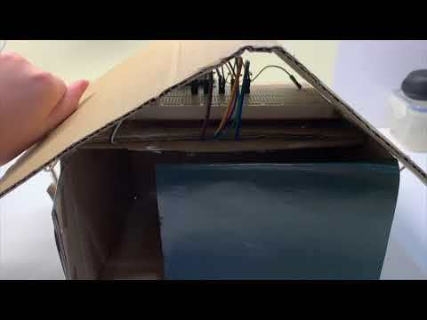
The Haunted House
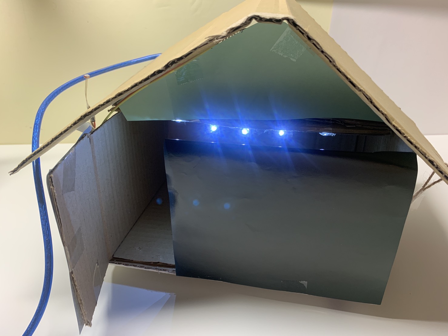
This project is a model of the haunted house, which can be a scene of a movie or a video. Last time when I'm making a short film, I found out that if the background of the scene is more detailed then it can create a better atmosphere.
The light in this project will get darker as it is closer to the night, and finally, the light would be totally turned off when the sun disappears. If it is afternoon, then you can leave some of the space from the Photoresistor so that some of the light would still shine.
You may put some characters inside the house and create your video if you want.
Follow the steps below to create your own haunted house!
Supplies
- A big piece of cardboard (cover the Breadboard and make the haunted house)
- LEDs as many as you want (can be red, yellow, blue, or white, in this project I choose to use white because it seems to be scarier for me)
- A Photoresistance (to control the amount of the LEDs)
- 1 blue resistor
- The amount of the brown resistor will depend on how many LEDs you want for your haunted house
- Scissors (to cut the cardboard)
- Colored papers (to cover the breadboard, including wires, resistor, LEDs, etc.)
- Tape (tape all the colored paper together and tape the wires on the ceiling of the house)
- Some wires (you need at least 8 wires, this is only for one LED. And if you want to add more LEDs you will need to add three wires as you adding the LEDs)
- Arduino Uno R3
Connect the Photoresistances!

Follow the picture shown above.
- Connect 5v (Arduino Uno R3) to anywhere on the breadboard
- Connect GND to the negative side of the breadboard
- Connect A0 beside where you connected 5v to
- Pick up your photoresistor and connect it on the same row (not the alphabets side but the numbers side) of where you connect A0 and 5v, in which one side of the photoresistor would be on the same row of A0 and another one would be on the same row of the 5v.
- Finally, it is time to connect the LEDs!!!
- From the Arduino Uno R3, D7 will be connected anywhere on the breadboard
- D6 connected beside D7 but leave some space for the wires to put
- Continue the step if you want more LEDs
- When you finish connecting the wires it is time to connect the resistors
- Connect one side of the resistor to the negative side and another side connect to another row right beside where you connect the wires to (Ex: D7, D6)
- Continue to put on the resistor, every LED needs a resistor
- After finish connecting resistor, connect the LEDs to other new wires
- Remember the LEDs will always on the same row of where you connect the resistor and the wire
- The longer side of the LED will be on the left side, which the shorter side would be on the right side
- When you finish all the steps then you're almost done! Now you should move on to the coding!
See the coding below
Coding
Decoration
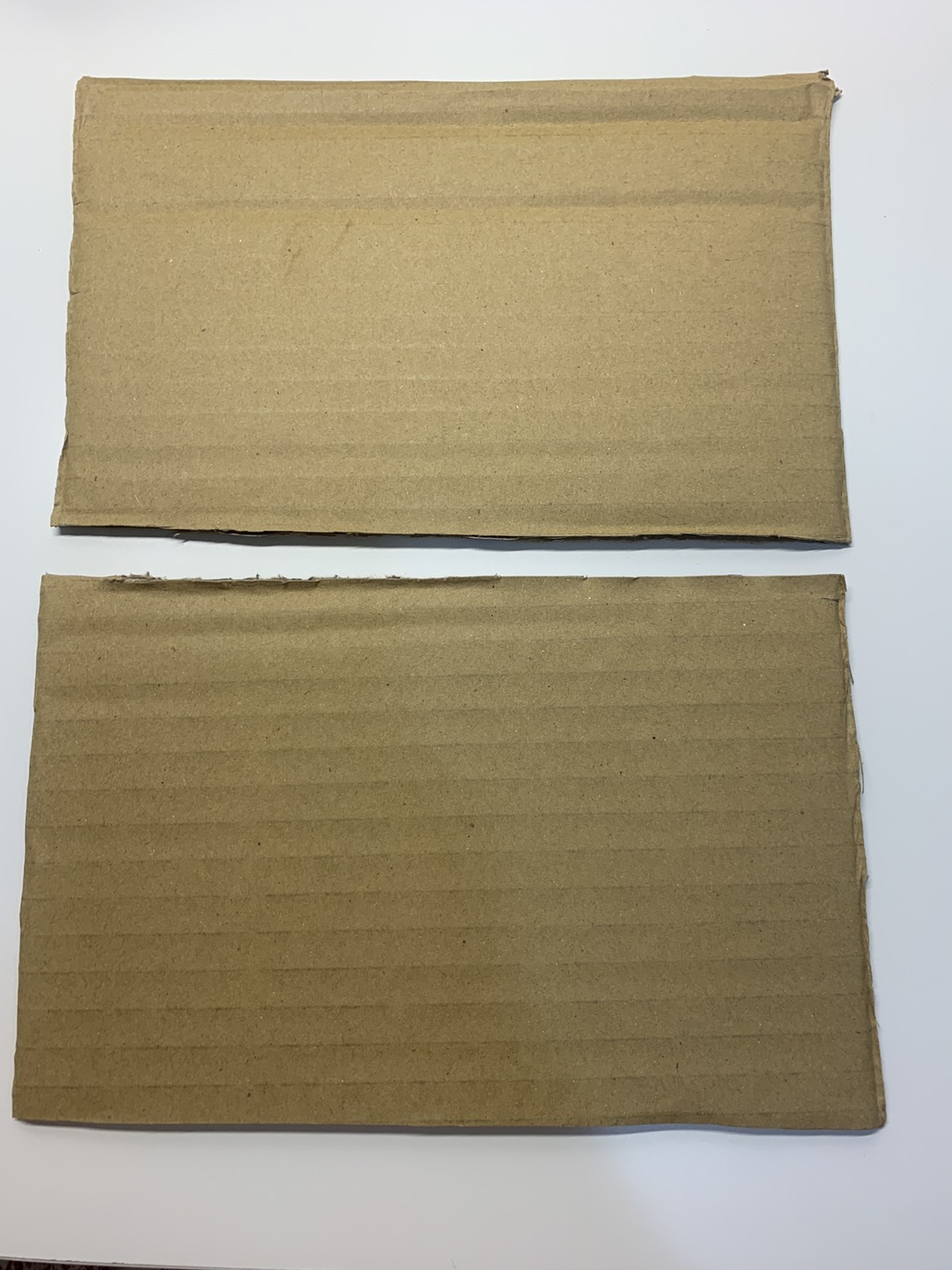
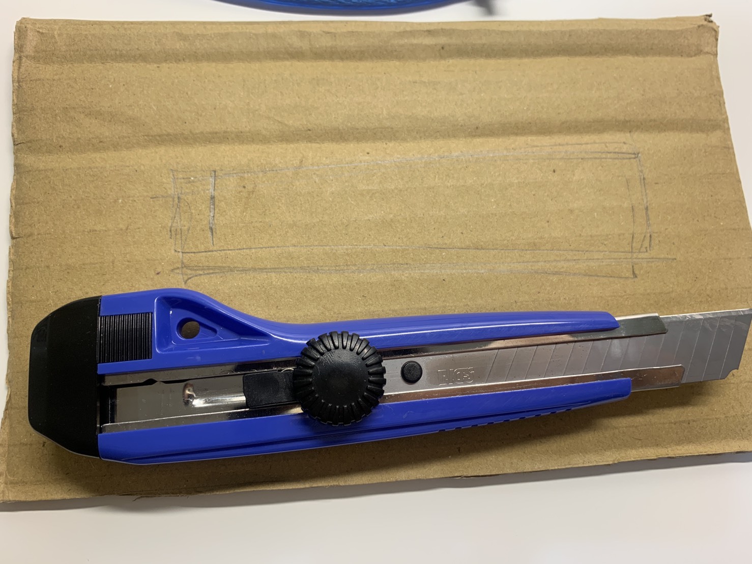
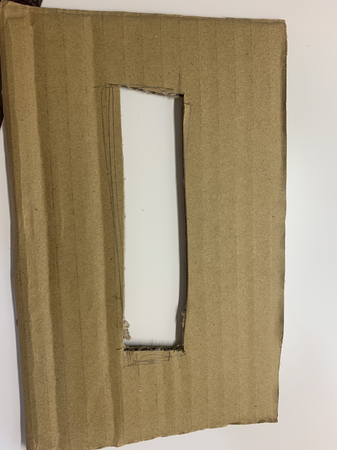
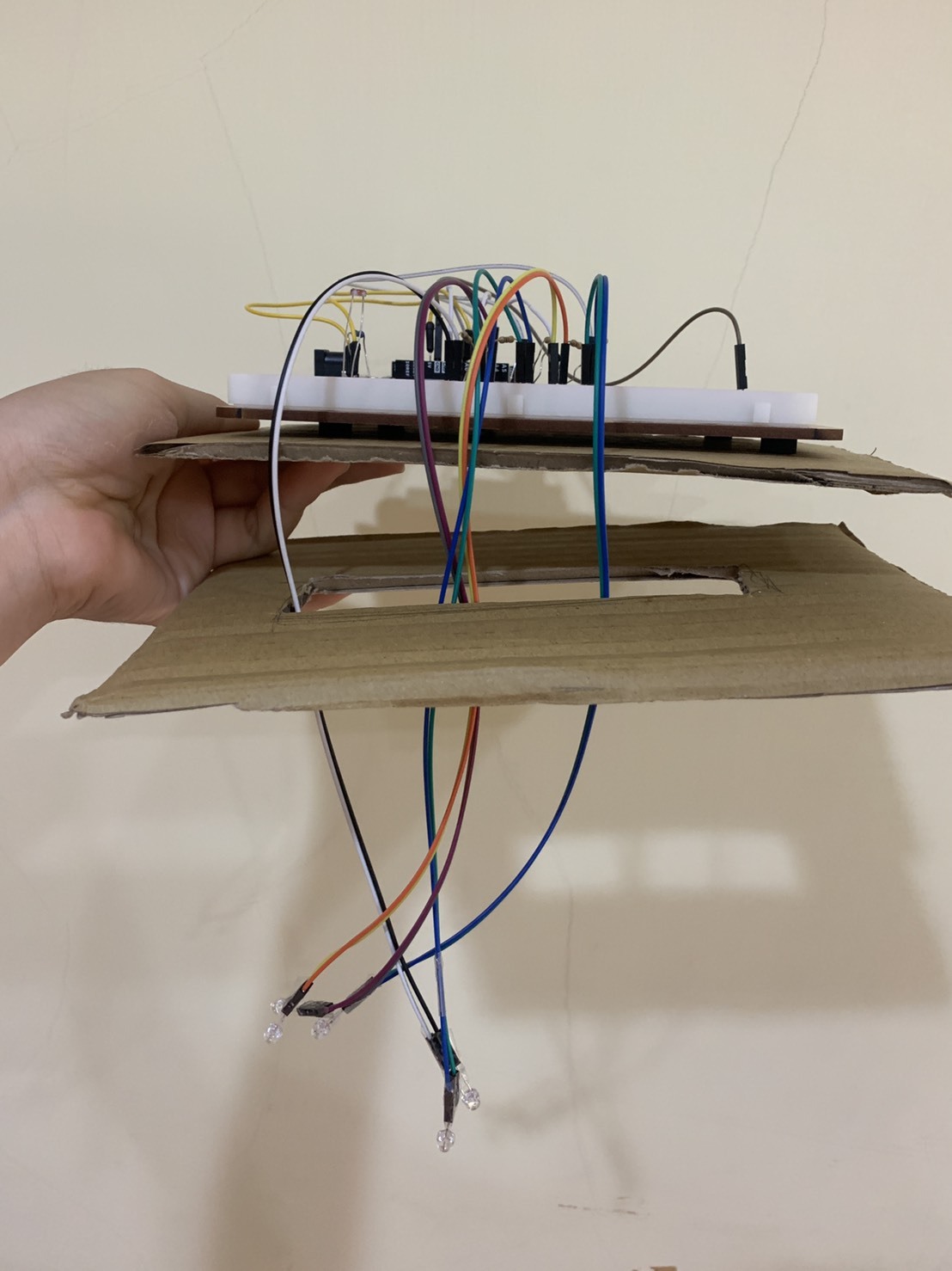
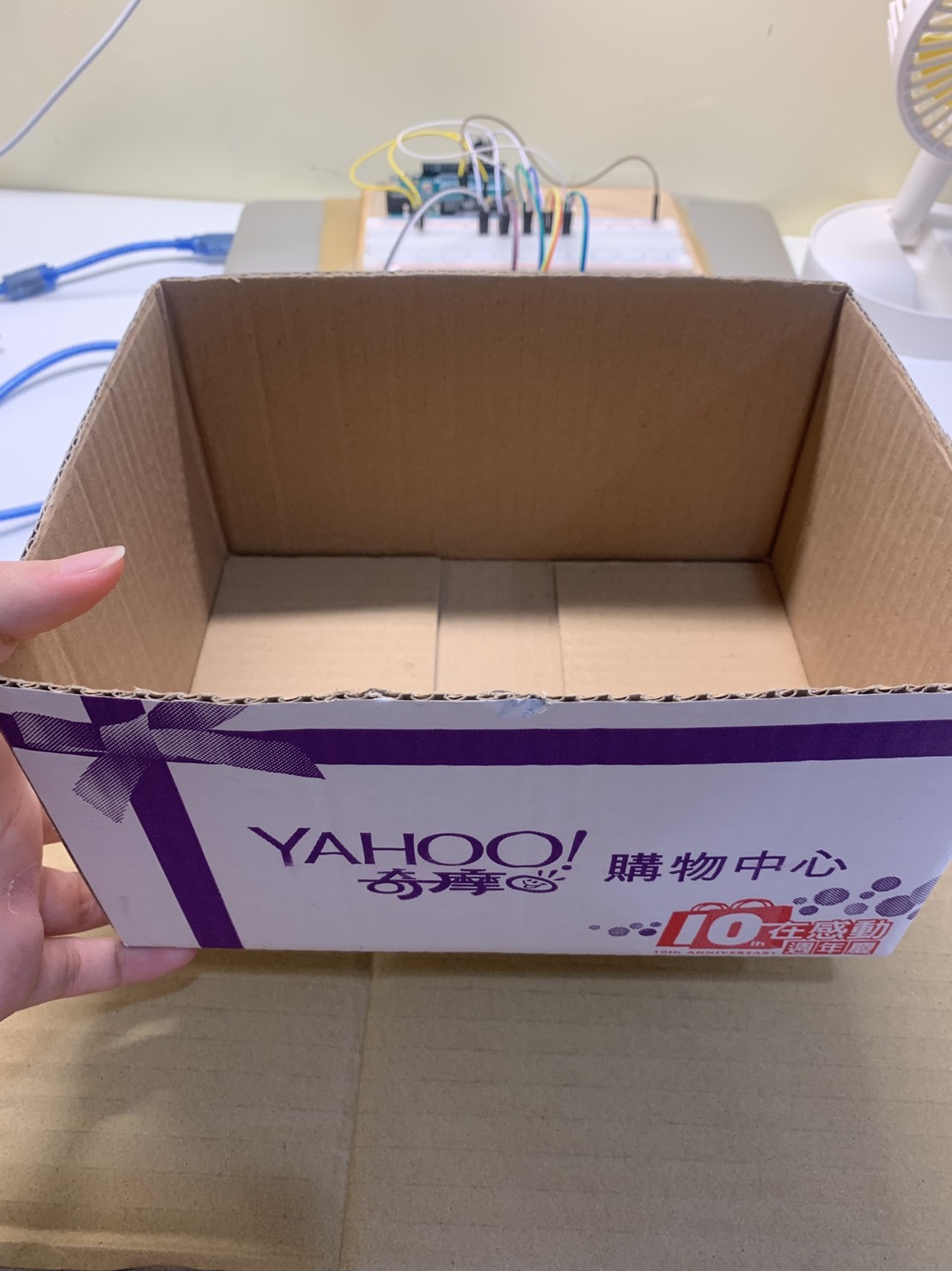
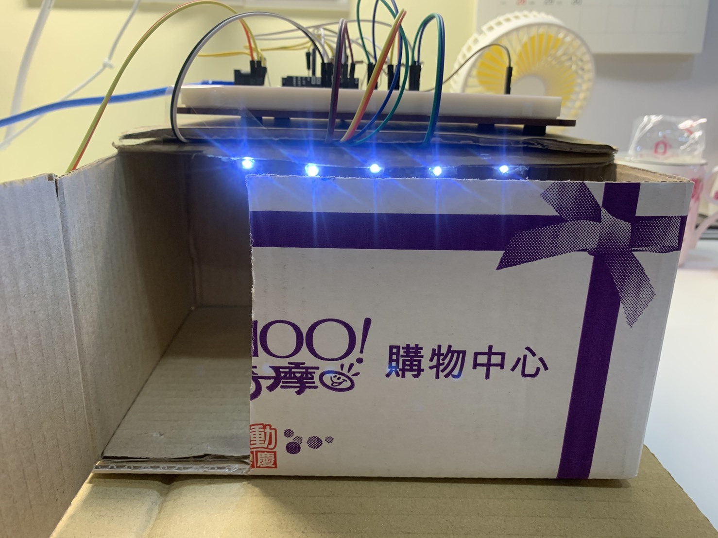
- Cut the cardboard into two pieces that fit the breadboard
- Cut a hole that can make the wires go through (it doesn't have to be beautiful because people won't see)
- Stick the cardboard and the breadboard together (remember that the wires should go through the hole)
- Find a box to put in the cardboard and the breadboard, it would be the ceiling of the house
Decoration P2
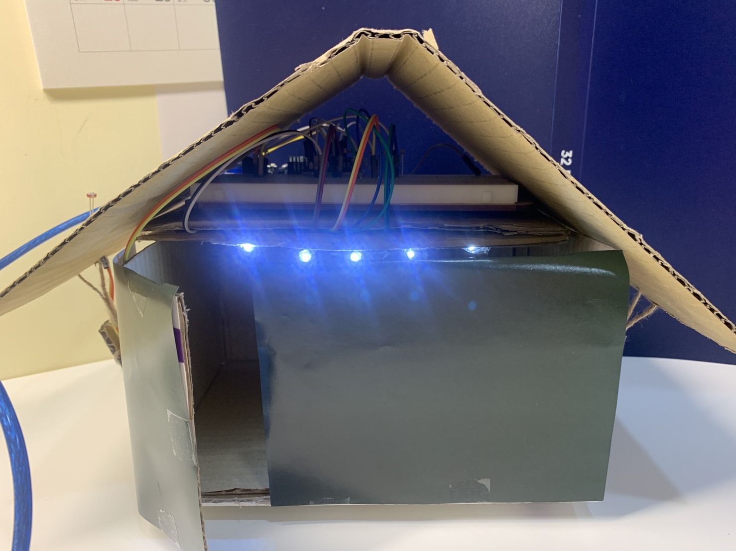
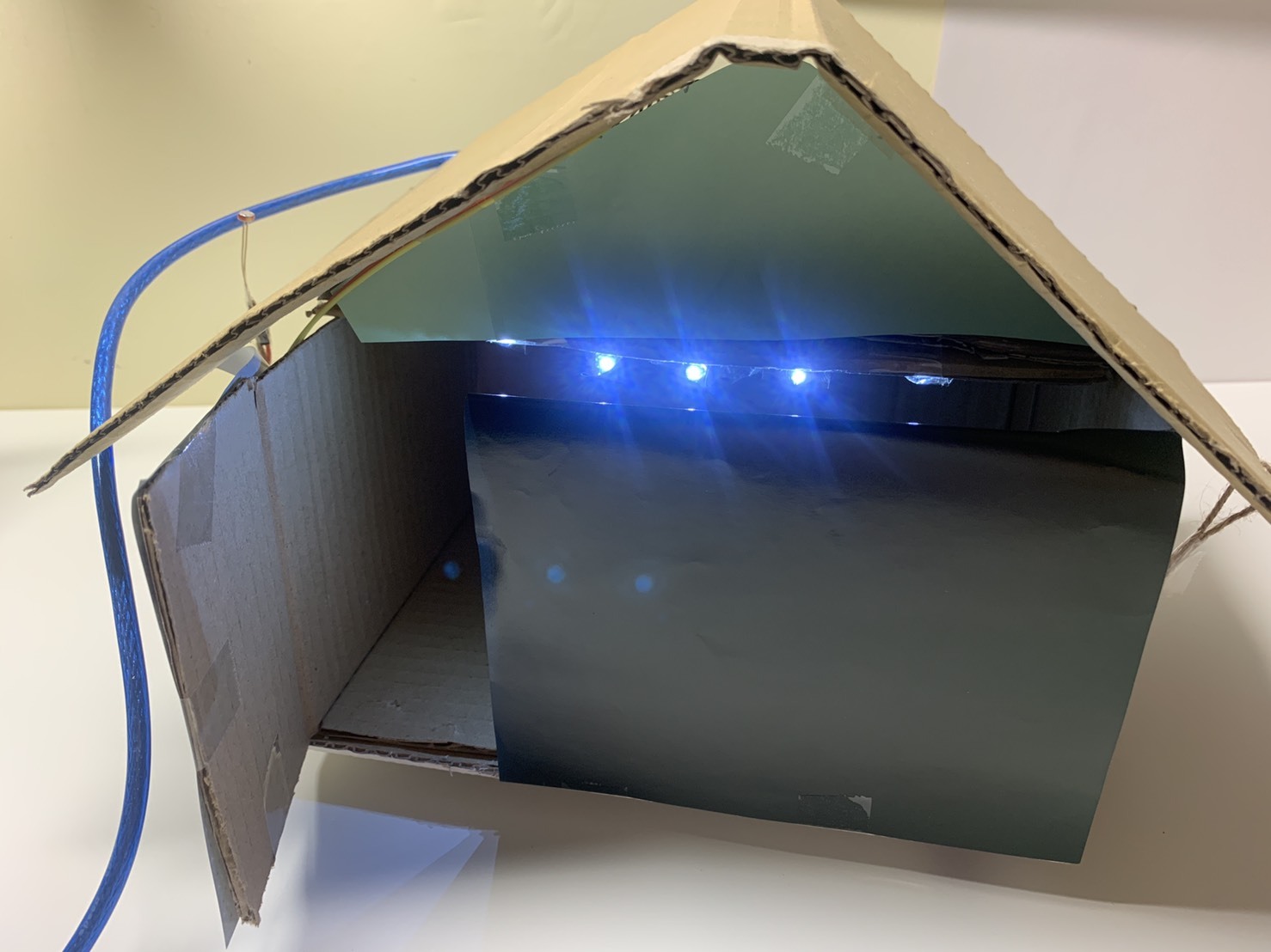
- Cut cardboard to cover the top of the breadboard
- Use the tape to stick the colored paper on the box to cover the ad
- Finally the project is done!!!
VIDEO (HOW IT WORKS, HOW IT REALLY LOOK, MATERIALS)
