The Gerber Derivimeter, the Ultimate Tool.
by ColMarti in Design > 3D Design
2055 Views, 12 Favorites, 0 Comments
The Gerber Derivimeter, the Ultimate Tool.
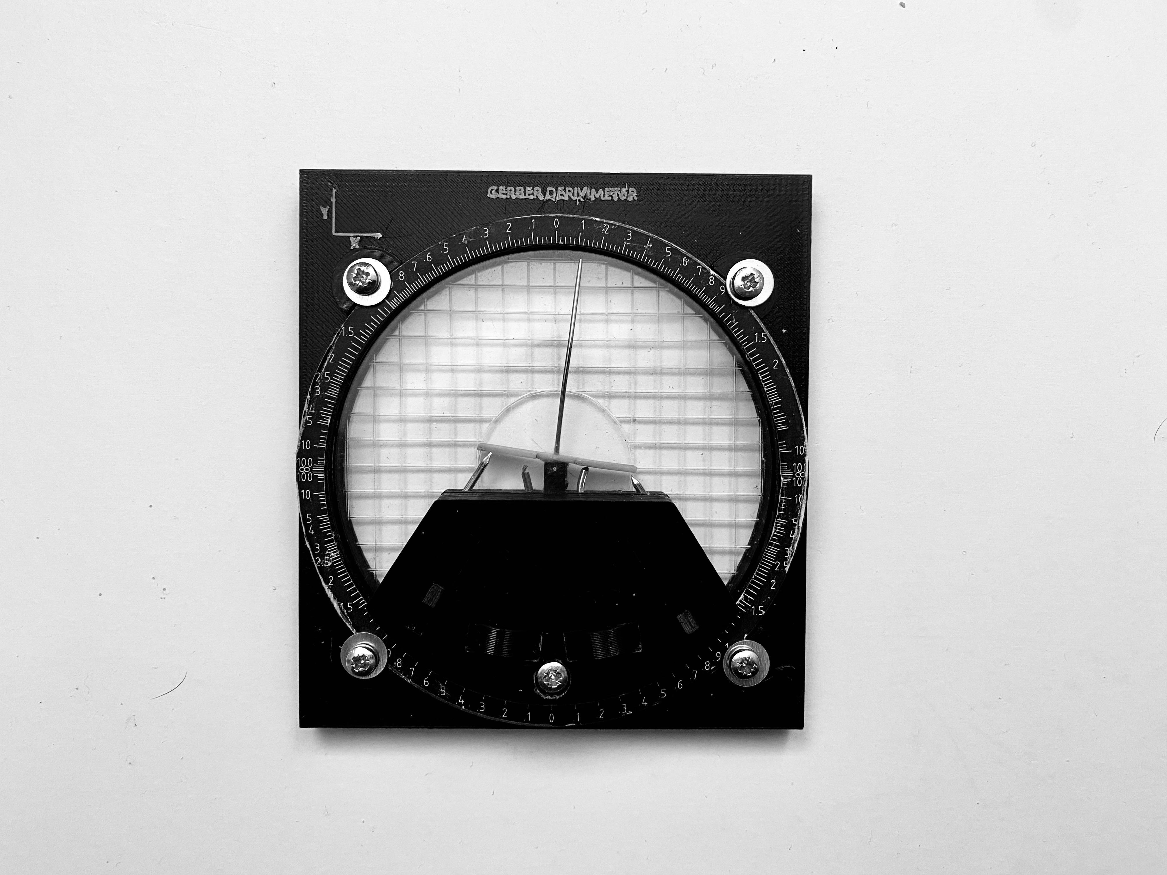
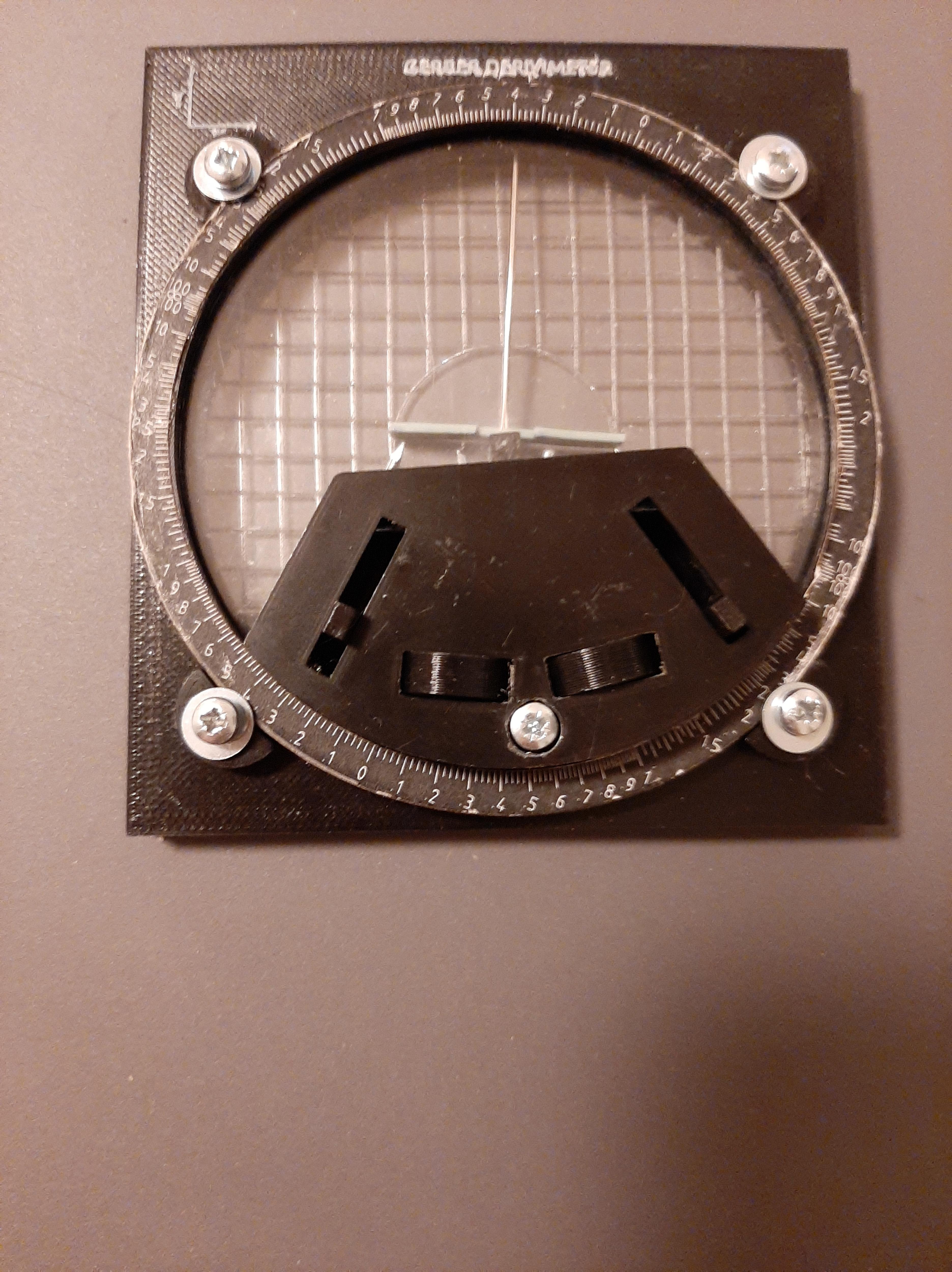
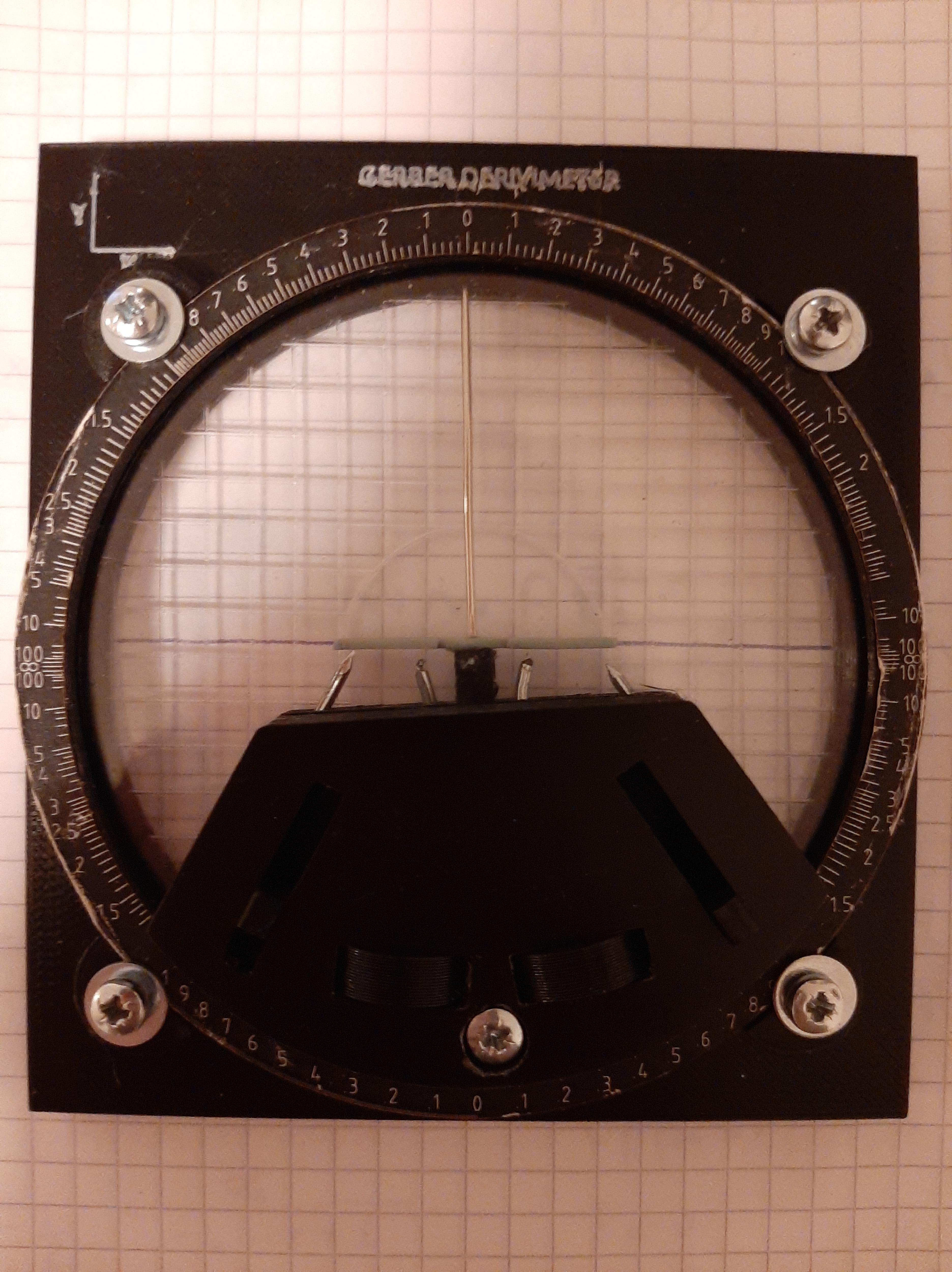
This is the ultimate tool (mostly if you are into math), the name itself says what the tool does. Derivatives!
and NOPE, it will not give you the equation of the derivative. However, it will give you the value of the derivative at any point if you have the original function plotted on paper, Crazy right? I saw this tool a few months ago and I was astonished by its functionality, It is incredible! This tool was used to find the value of derivatives of graphs in the 1950s when all the graphs were on paper. The tool was invented by Joseph Gerber an engineering master.
Links:
If you are interested in what the original Derivimeter looks like:
https://americanhistory.si.edu/collections/search/object/nmah_1215079
And if you want to know how it works watch this YouTube video: https://youtu.be/FSQErVZwh8s.
How did I design it?
Well, there is almost no information on this object, but it is possible to find the patent in scale. After researching online I managed to find one of the sides of the Derivimeter and everything was set. After many long hours of modelling, the was still much to be done. However, I managed to complete it, and it works almost perfectly. The tool was designed in Sketchup® and the latest files can be found in the last section.
BEFORE PROCEEDING:
I assume you already know how to use all the tools listed in the section below
Let's get started!
Supplies
To be able to build the Derivimeter you will need the following:
Tools:
- 3D printed
- Laser cutter
- Printer
- Screwdriver
- Bolt cutter
- Cutter
Material:
- Black filament
- White filament
- Super glue
- 5x - m3 nuts and screws, Length=1cm.
- 2x - m3 nuts and screws, Length=2.5cm
- Needle:
- 1x Diameter=1mm, Length 4.5cm
- 1x Diameter=0.6mm, Length 3cm
- Plexiglas 100mm, 200mm, 7mm
- Very flexible phone cover.
- 4x Nails Diameter=1.3mm, Length 2.5cm
- 4x Nail washer Outer diameter=0.9mm, Inner diameter=0.4mm
- 5mm square A4 paper.
PRINT!
.png)
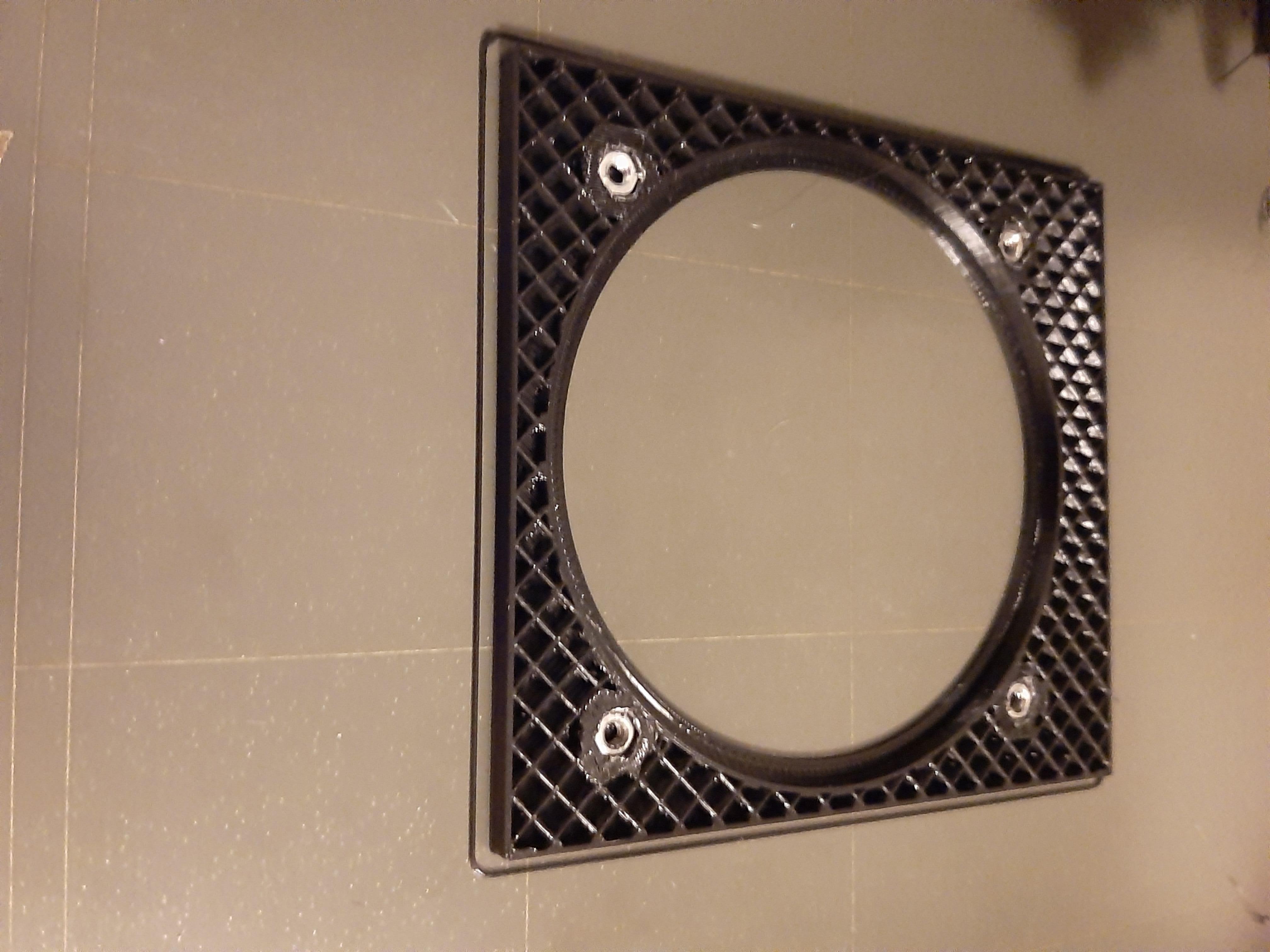
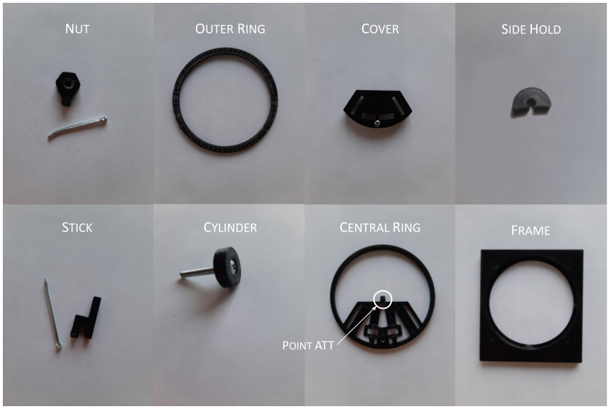
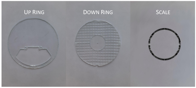
At the end of this step, you should have every part printed (Print files at the end). The picture above shows the name of each part (This will be useful later on). The print should be stopped for the following list of parts at the indicated layer to be able to insert m3 nuts in the print:
Part and Stop Layer:
- Nut 1.85mm
- Main Frame 1.85mm
- Central Ring 1.85mm
You will need to print:
With 0.3mm or higher quality (I used 0.3mm):
- 2x Nut
- 2x Stick
- 2x Cylinder
- 1x Frame
- 1x Cover
- 1x Outer Ring
- 4x Side Hold
With the highest quality (I used 0.05mm):
- Central Ring with support only on the "Point ATT" shown in the figure
Additional stops:
- The print should be stopped for a colour change before the final layers for the part "Frame"
CUT!
In this step, we will go through the step of cutting with the laser cutter. the files can be found in the last section and are .dxf. Additionally, you will need to print the "SCALE.pdf" file with your paper printer.
1. To cut SCALE.pdf:
Now, this is one of the hardest parts of this build, firstly you will need to load the SCALE.dxf on your laser cutter. Try to centre the red corner shown in the SCALE.pdf with your laser-cut corner (The red corner is not completely aligned with the file for the laser cutter).
2. Cut the other stuff
Downloads
BUILD
The pointer assembly is the last hard step in the project.
Firstly:
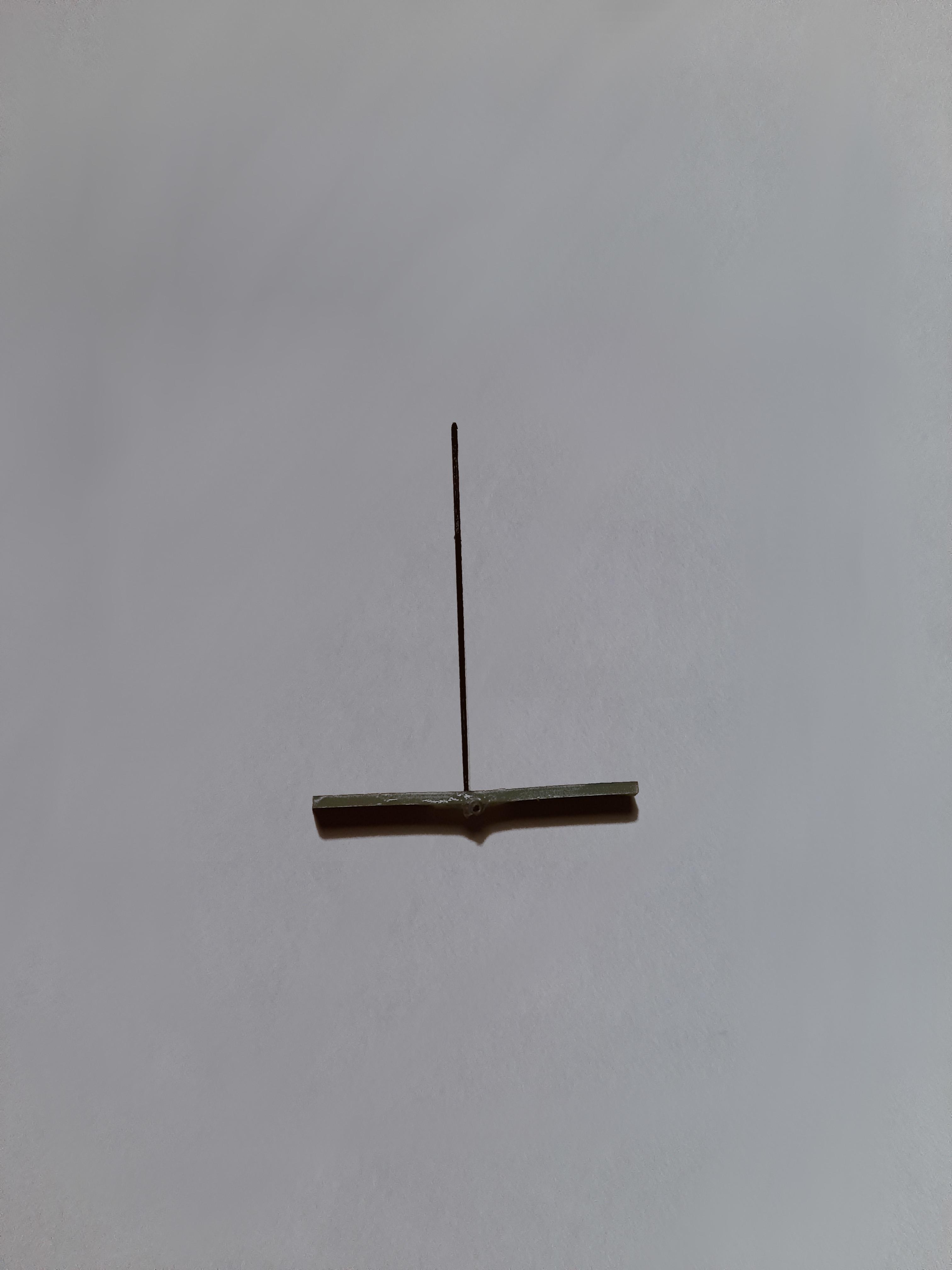
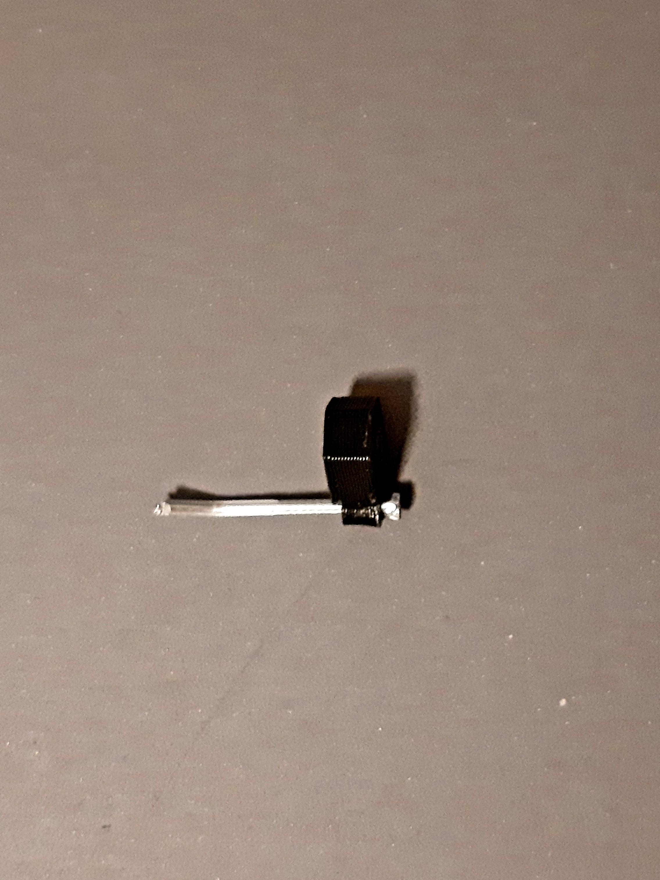
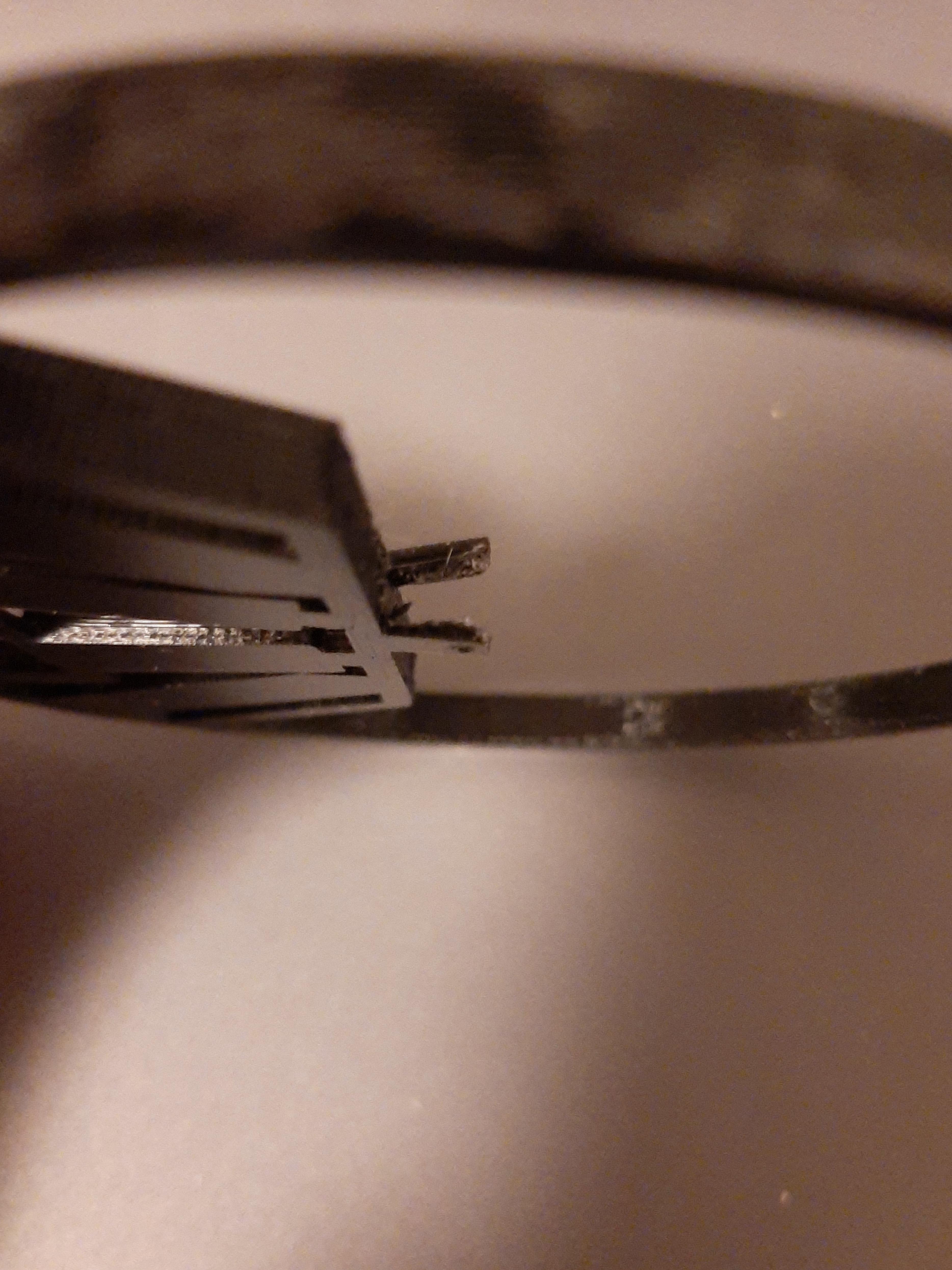
Insert the 0.6mm needle in the eye of the bigger needle (second picture). Glue them at 90 degrees of each other using super glue.
Once that is done, cut so that only 2.5mm remains on each end of the smaller needle from the eye of the bigger needle.
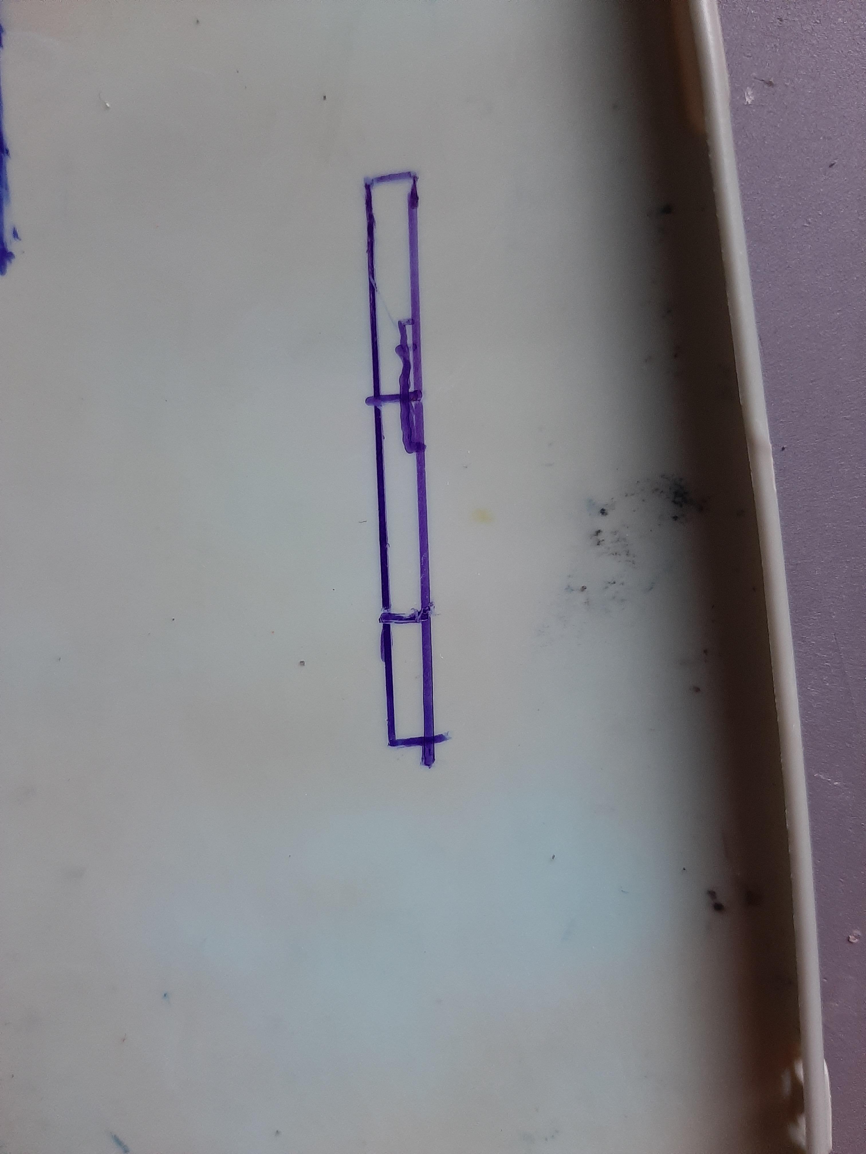
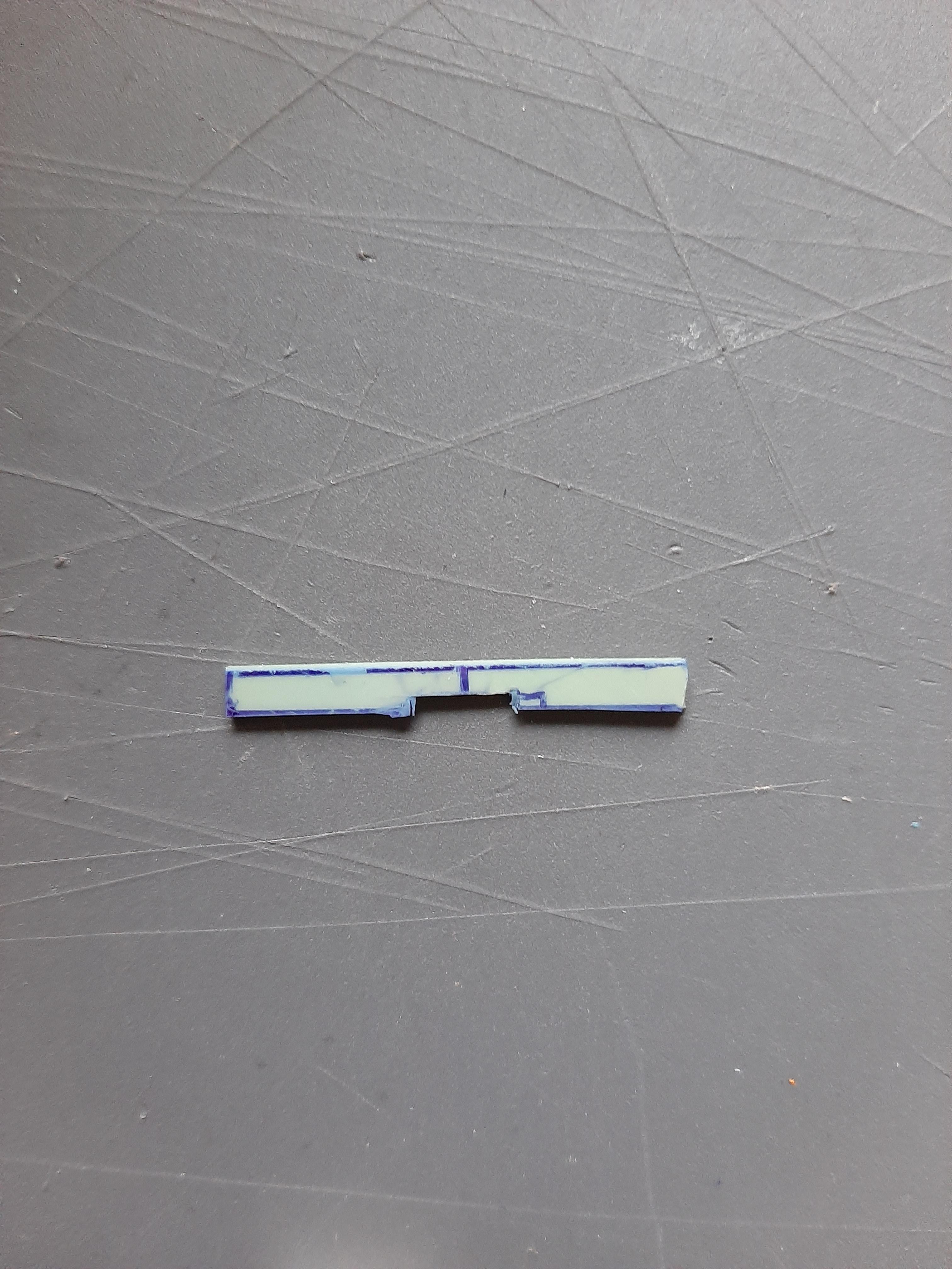
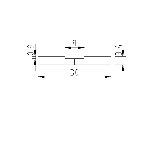
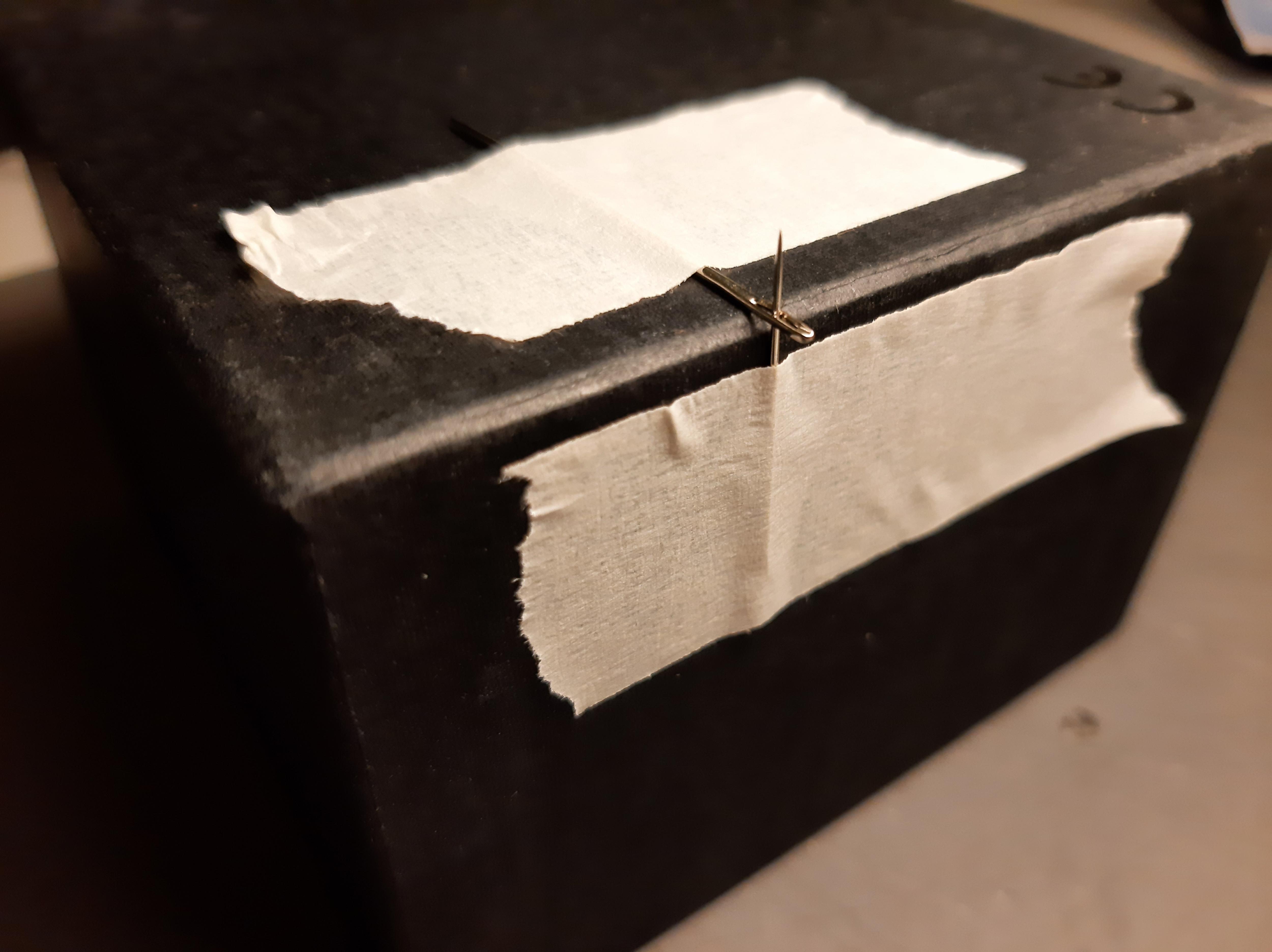
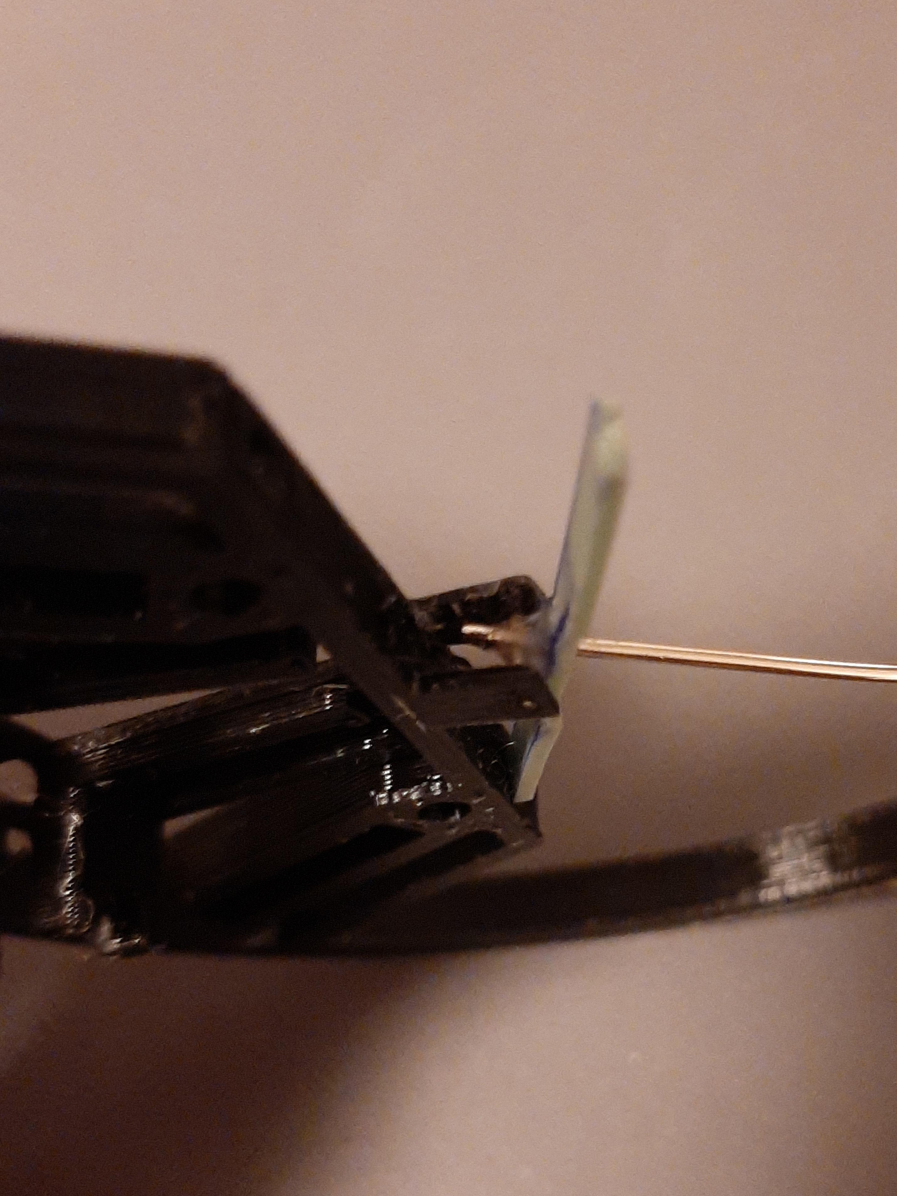
Time to cut your flexible phone cover, use a cutter to cut the shape as shown in the third figure (the unit of the figure is millimetres).
Now you have a ventilation system for your phone!
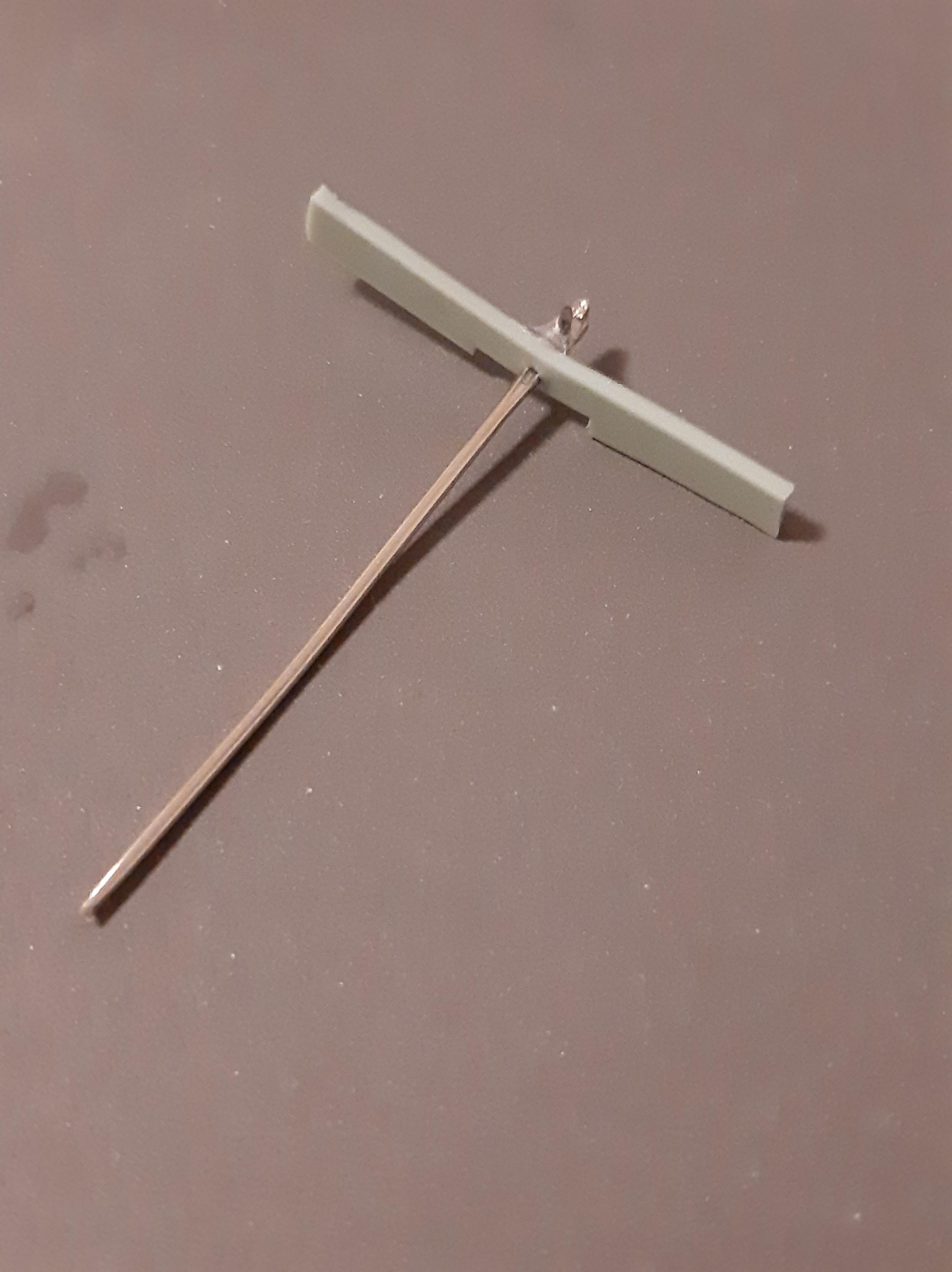
Insert the longer needle in the middle of the strip cut from the phone cover and glue it.
The Mechanism
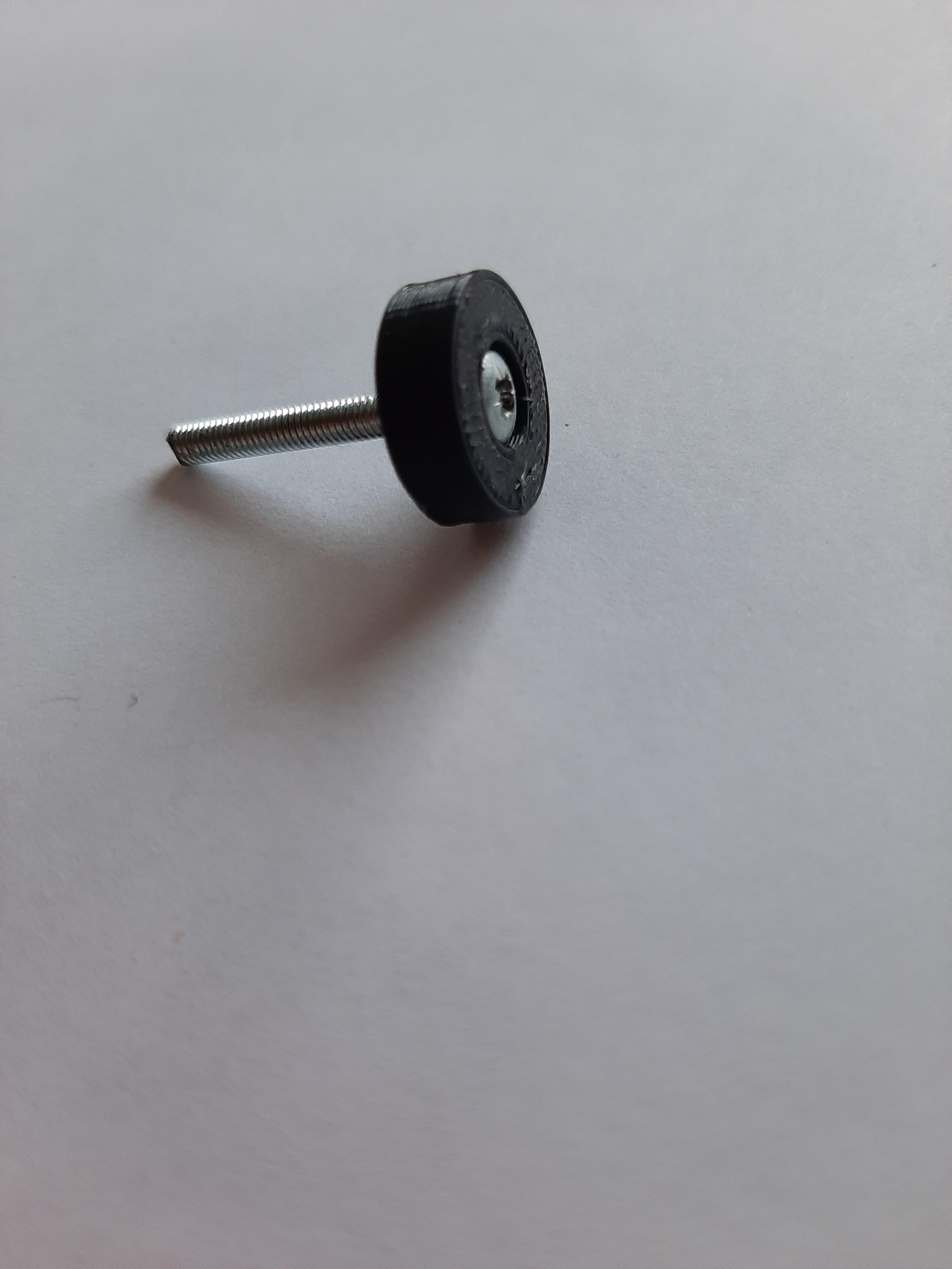
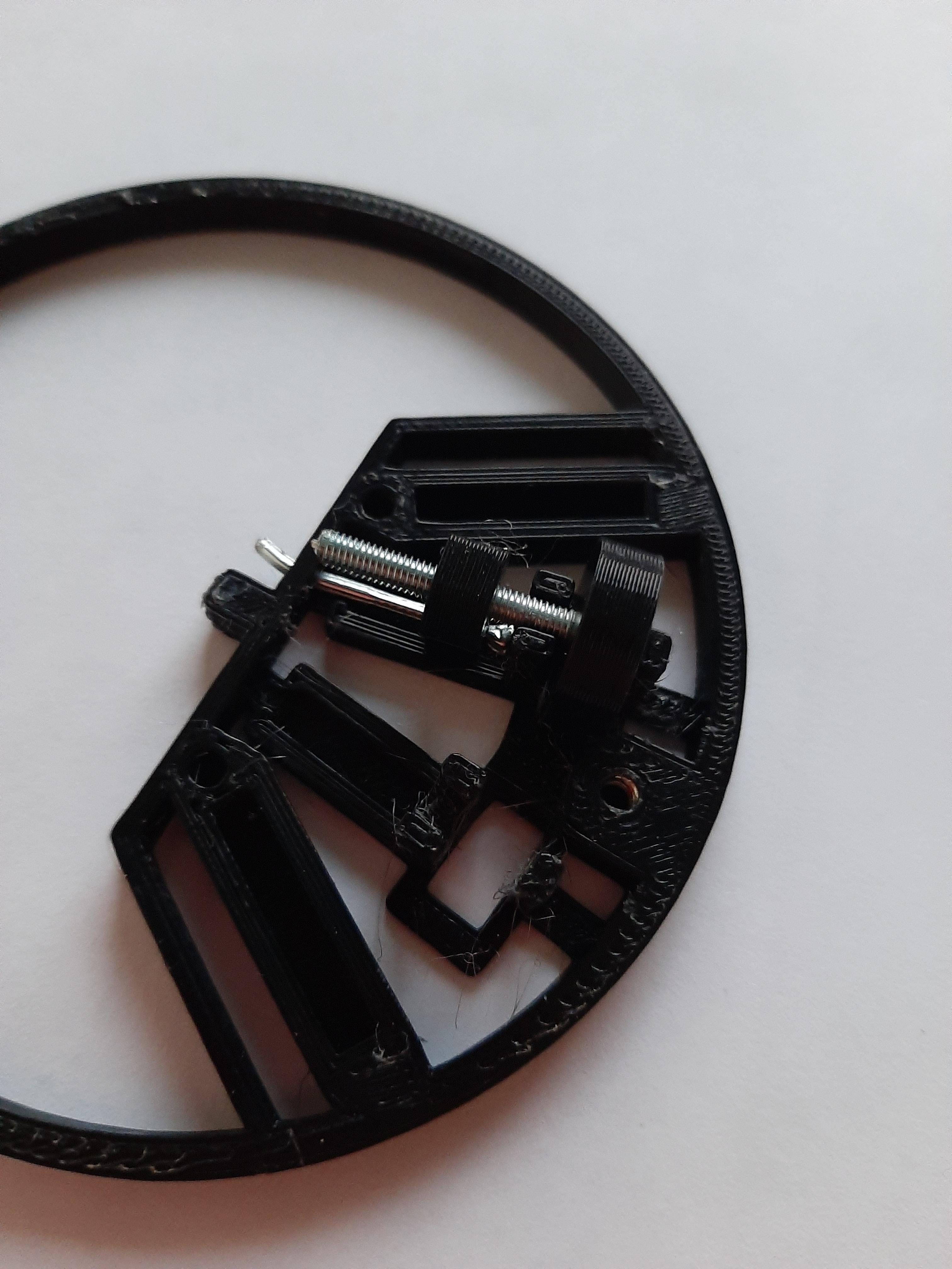
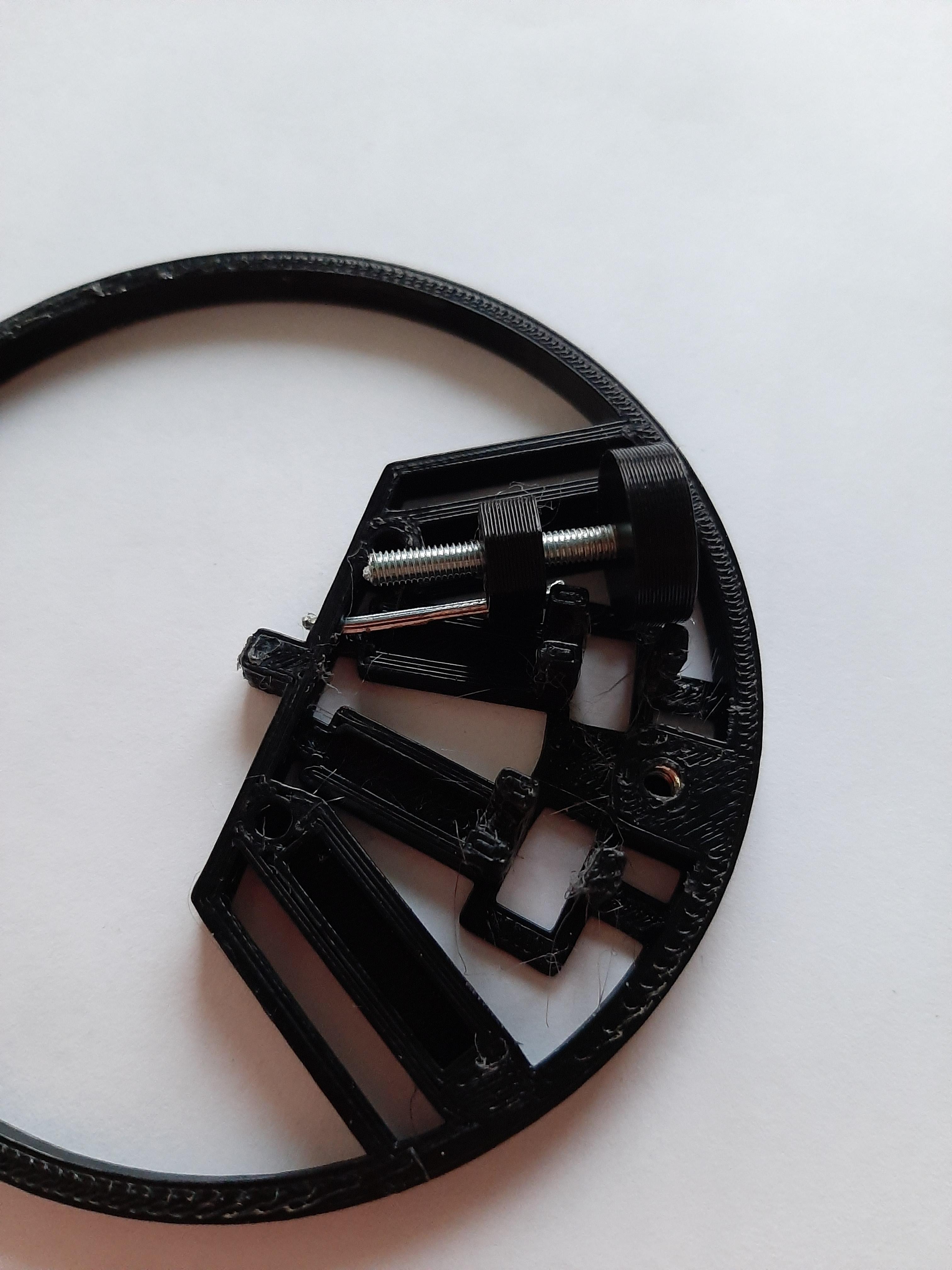
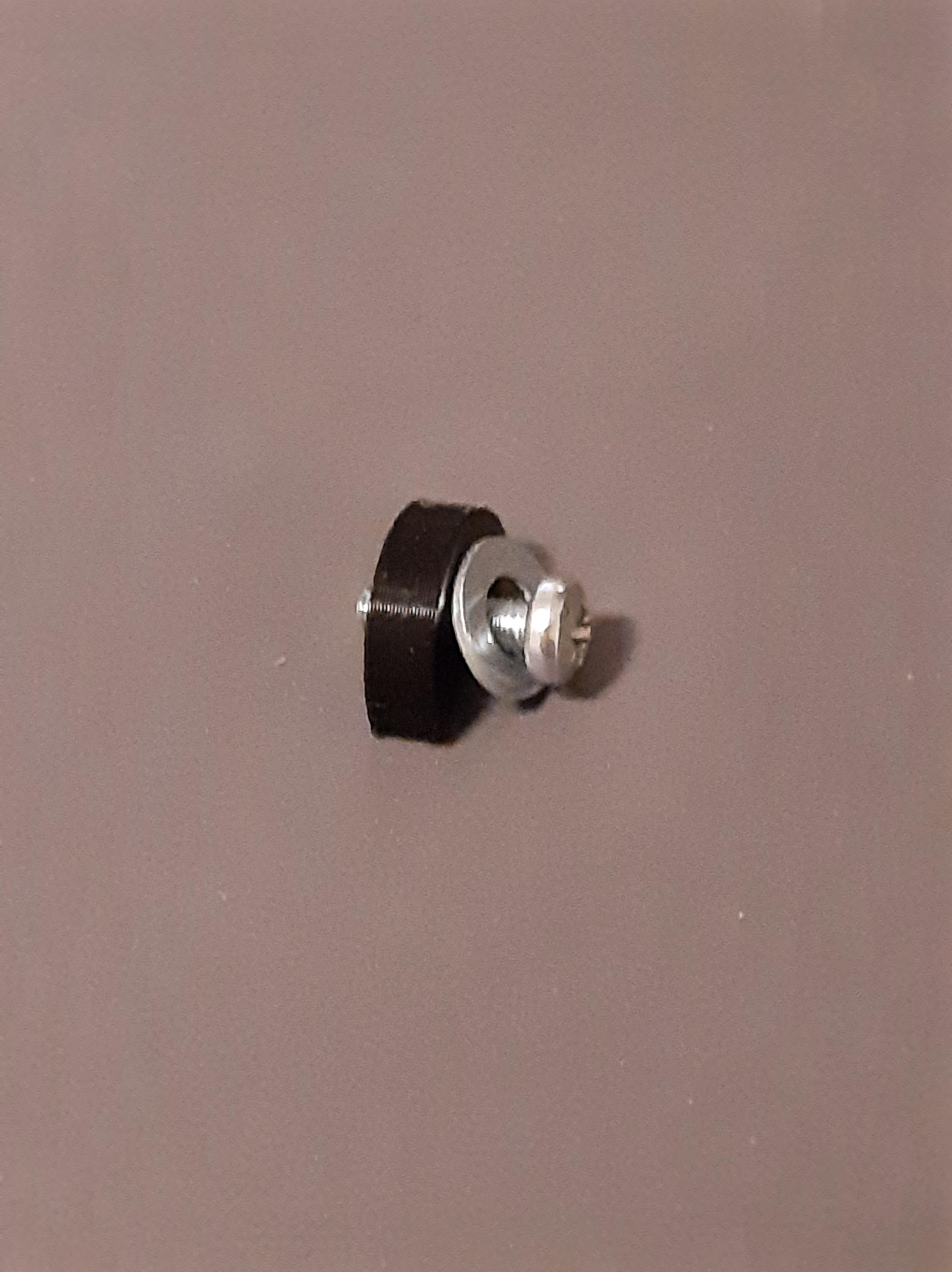
Glue a 2.5cm m3 screw into the cylinder with super glue. Repeat this step twice.
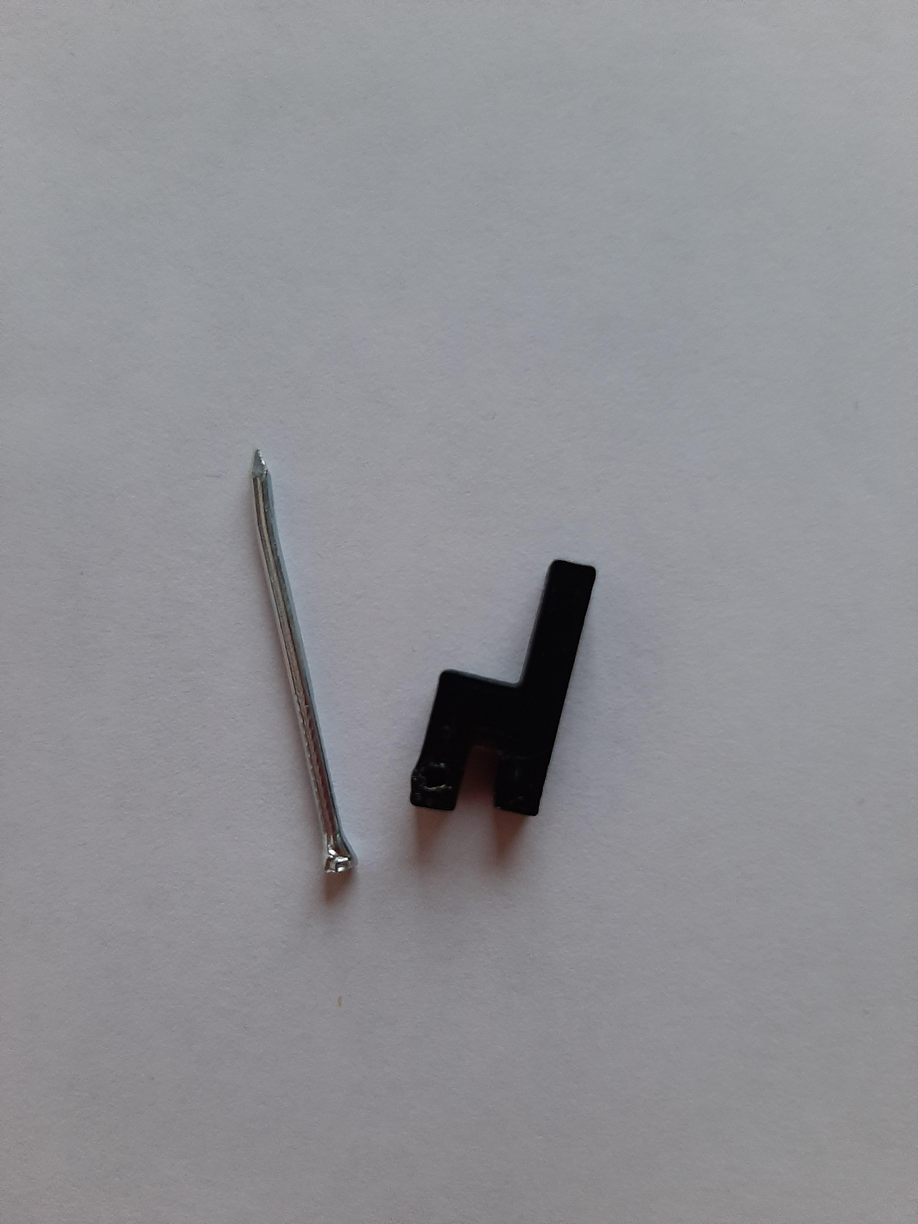
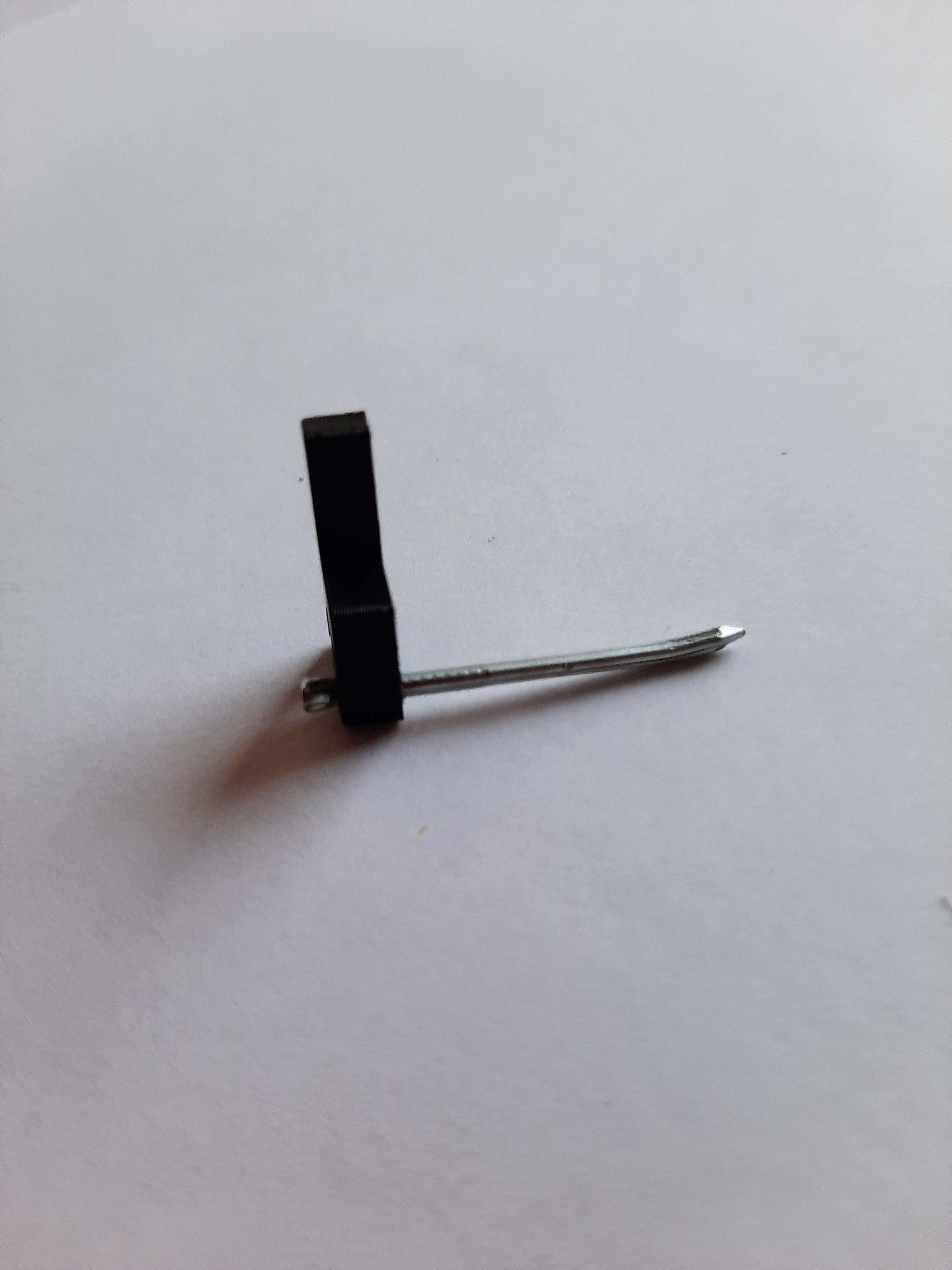
Insert the 1.3mm nail in the hole of the part "Stick". Then bend the tip of the nail upwards as shown in the figure. Do this step twice.
Insert the nail in the part "Nut" as shown in the figure, this time bend the nail sideways. Do this step twice, however, bend the nail once to the left and the other to the right.
Insert the component "nut" in the part "cylinder" first picture. By this step, you should have the above parts assembled.
This step is focused on the assembly of the part "Frame" with the part "Down Ring". First place the "Frame" aligned with the square paper. Once that is done, prepare the Down Ring, put glue on the Frame and place the Down Ring in the Frame, rotate it, so it is aligned with the square paper and therefore the Frame.
To mount the pointer, bend the two little strips in the "Central Ring" and insert the pointer. Then cut the long needle to be able to fit it into the Central Ring.
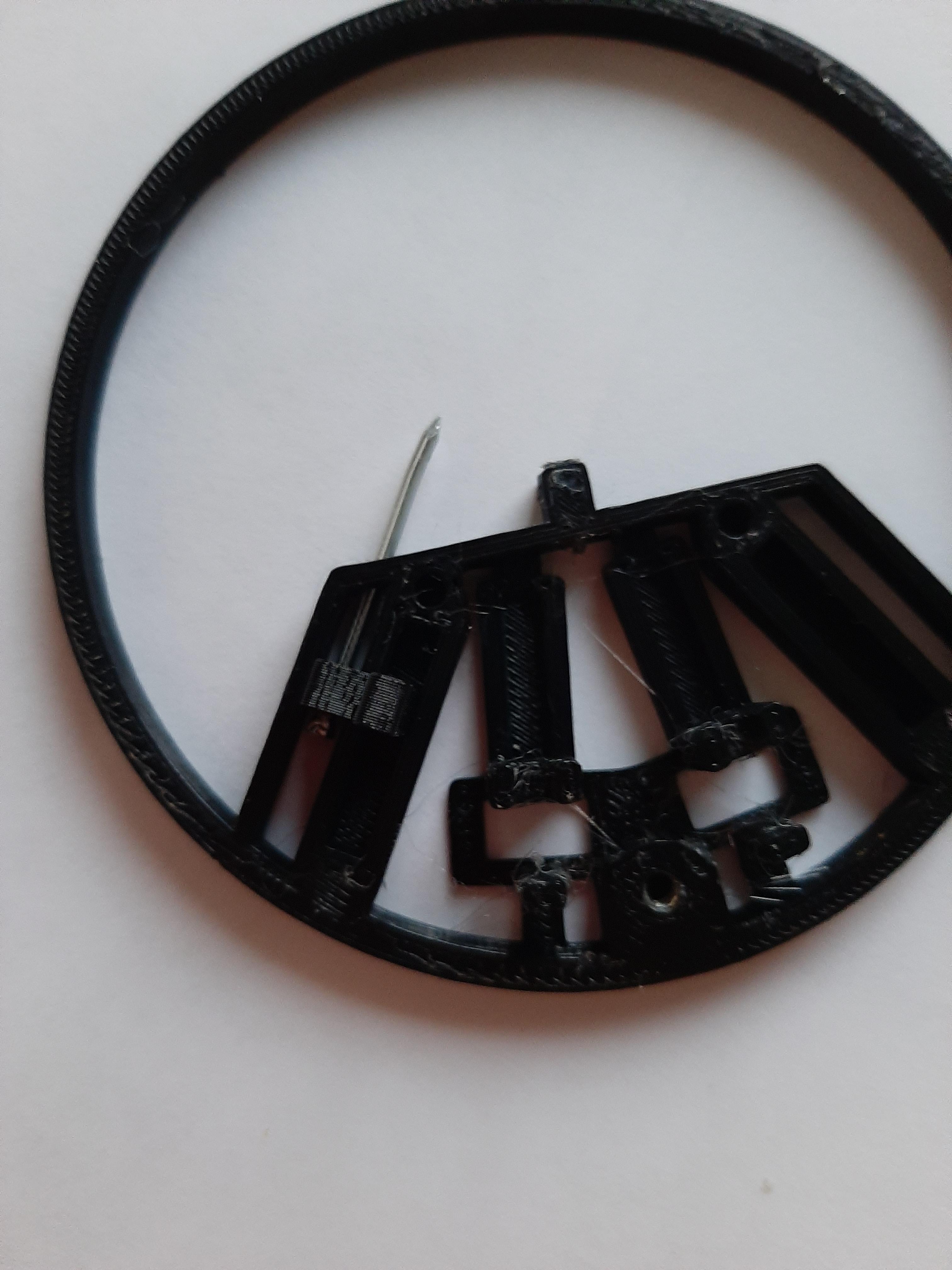
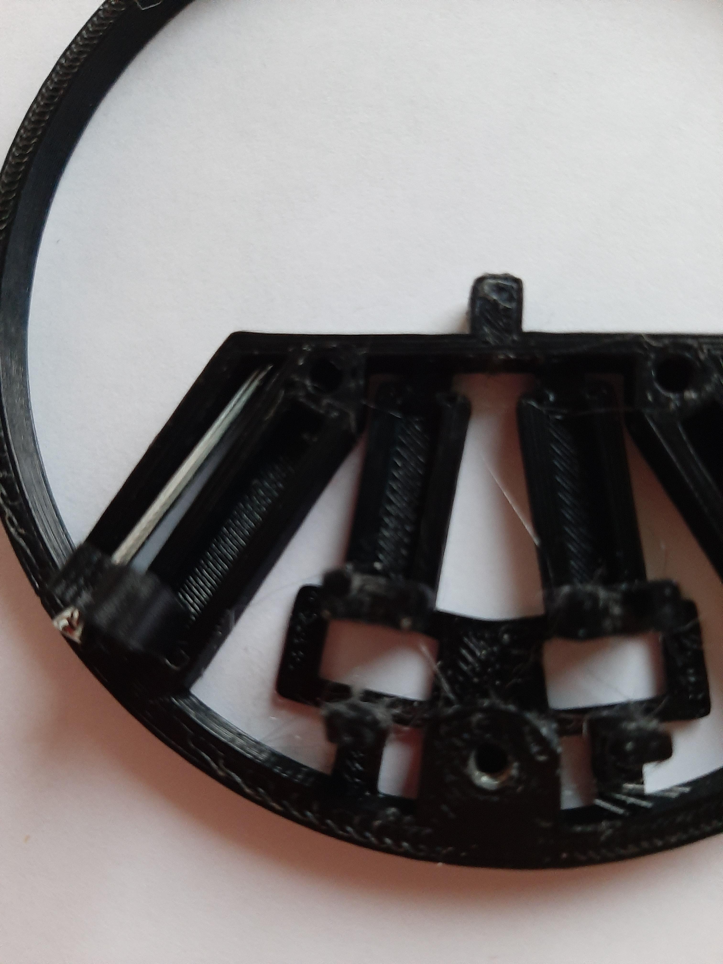
Once that is done insert the "sticks" and the Cylinder with the nut in their place. (The pointer should be already attached when inserting the components)
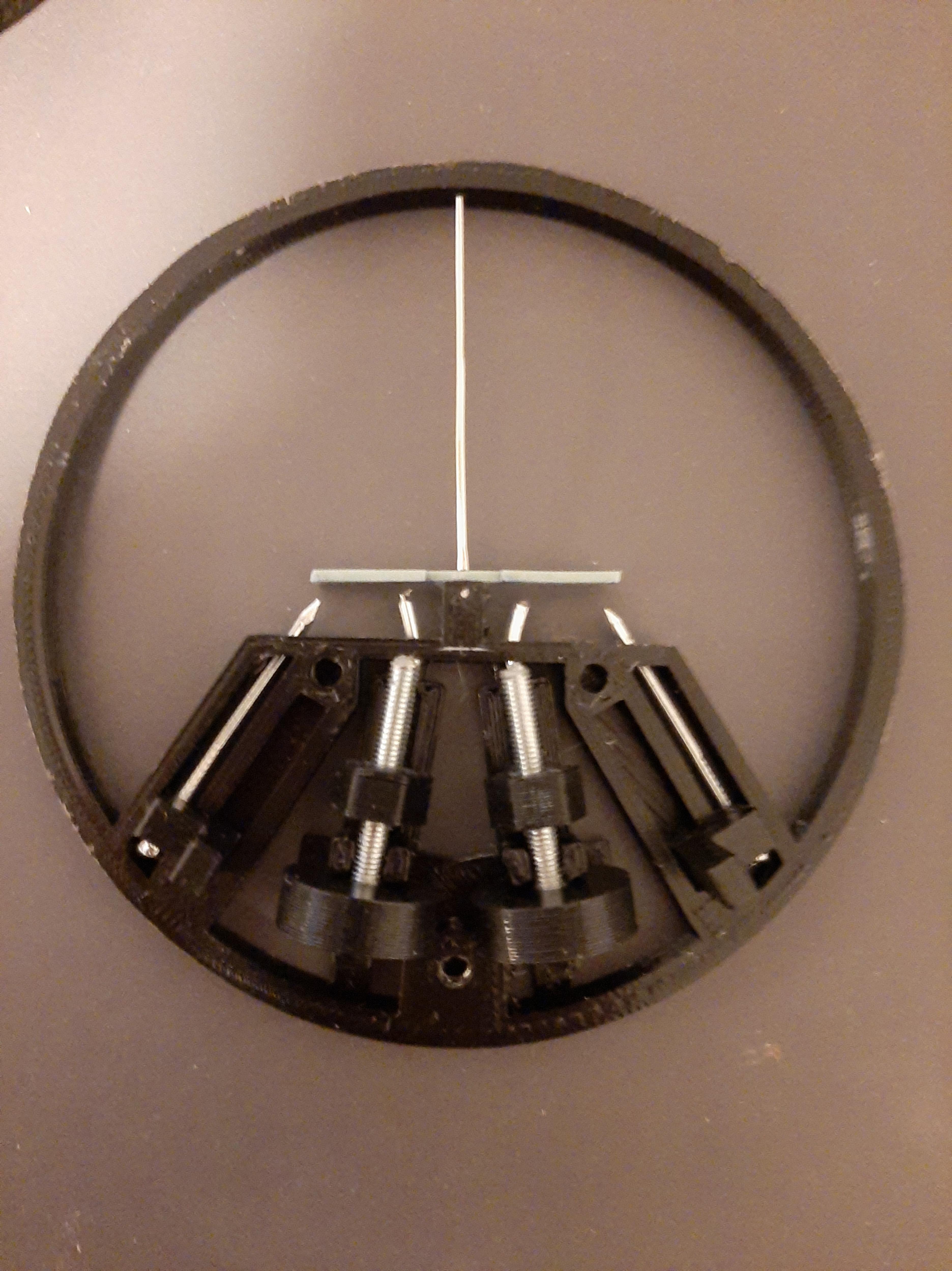
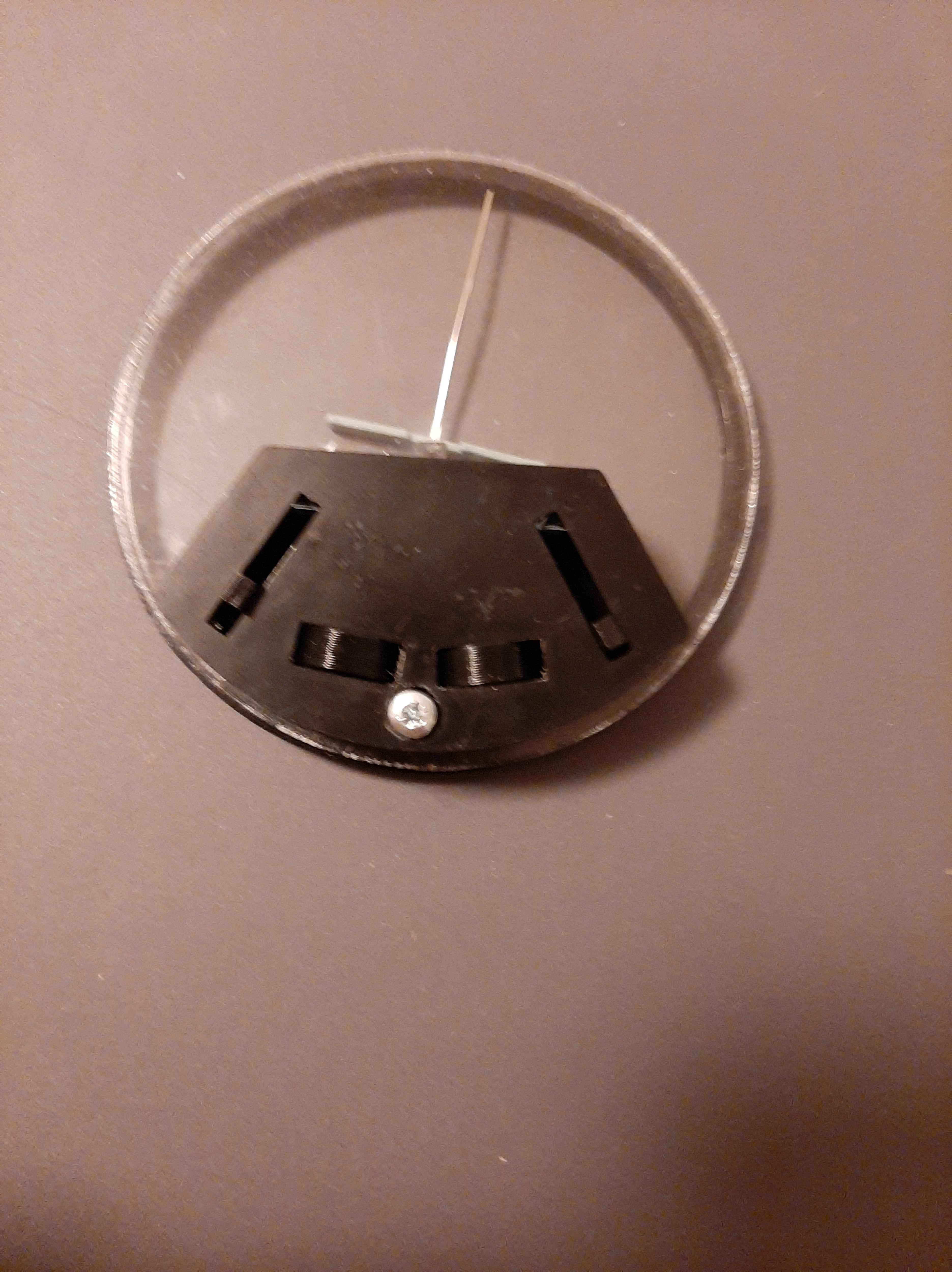
Put the "Up Ring" on top of the Central Ring then place the "Cover" on top and fix it using a 1cm m3 screw.
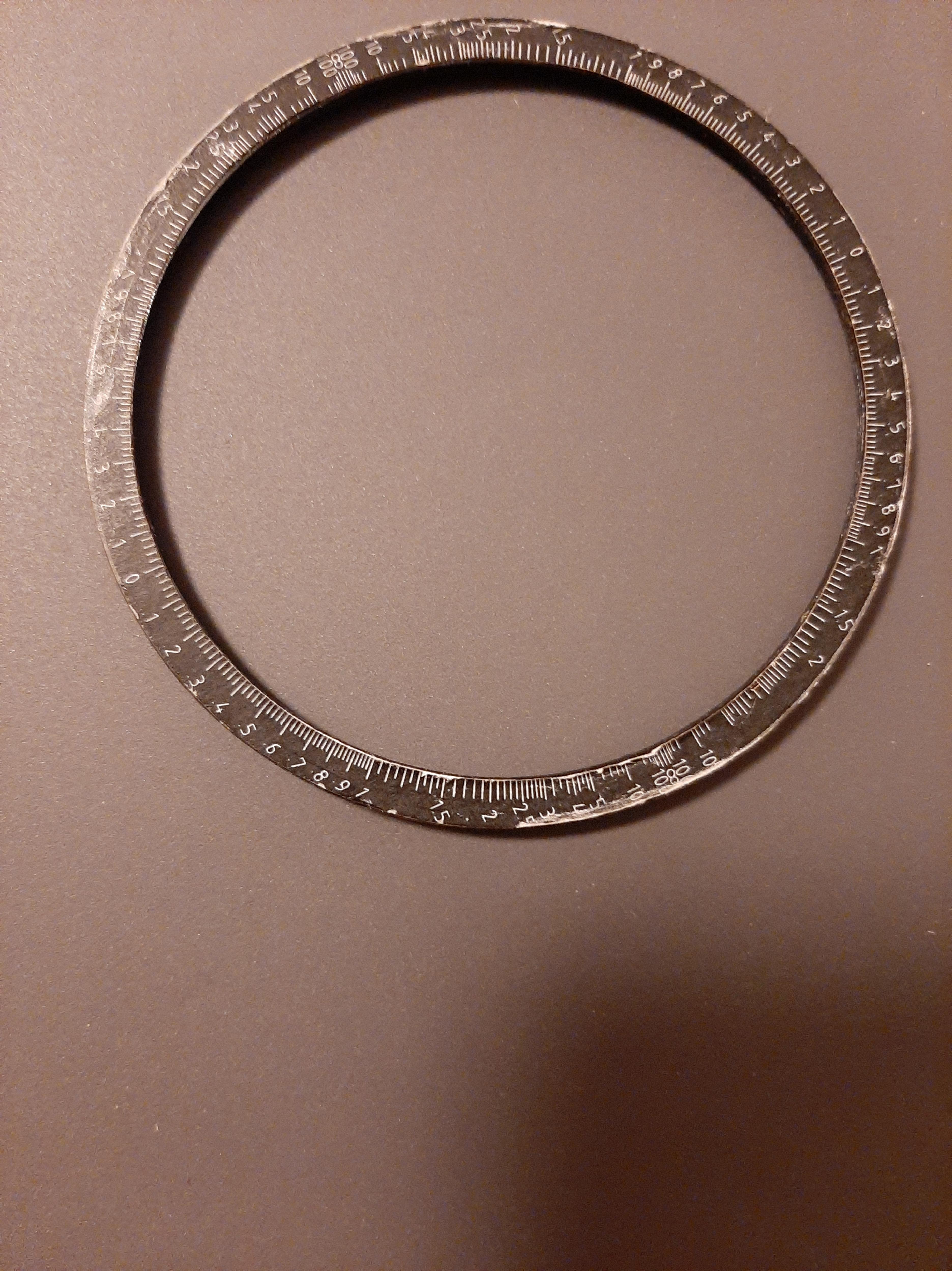
Glue the SCALE previously cut on the Outer Ring.
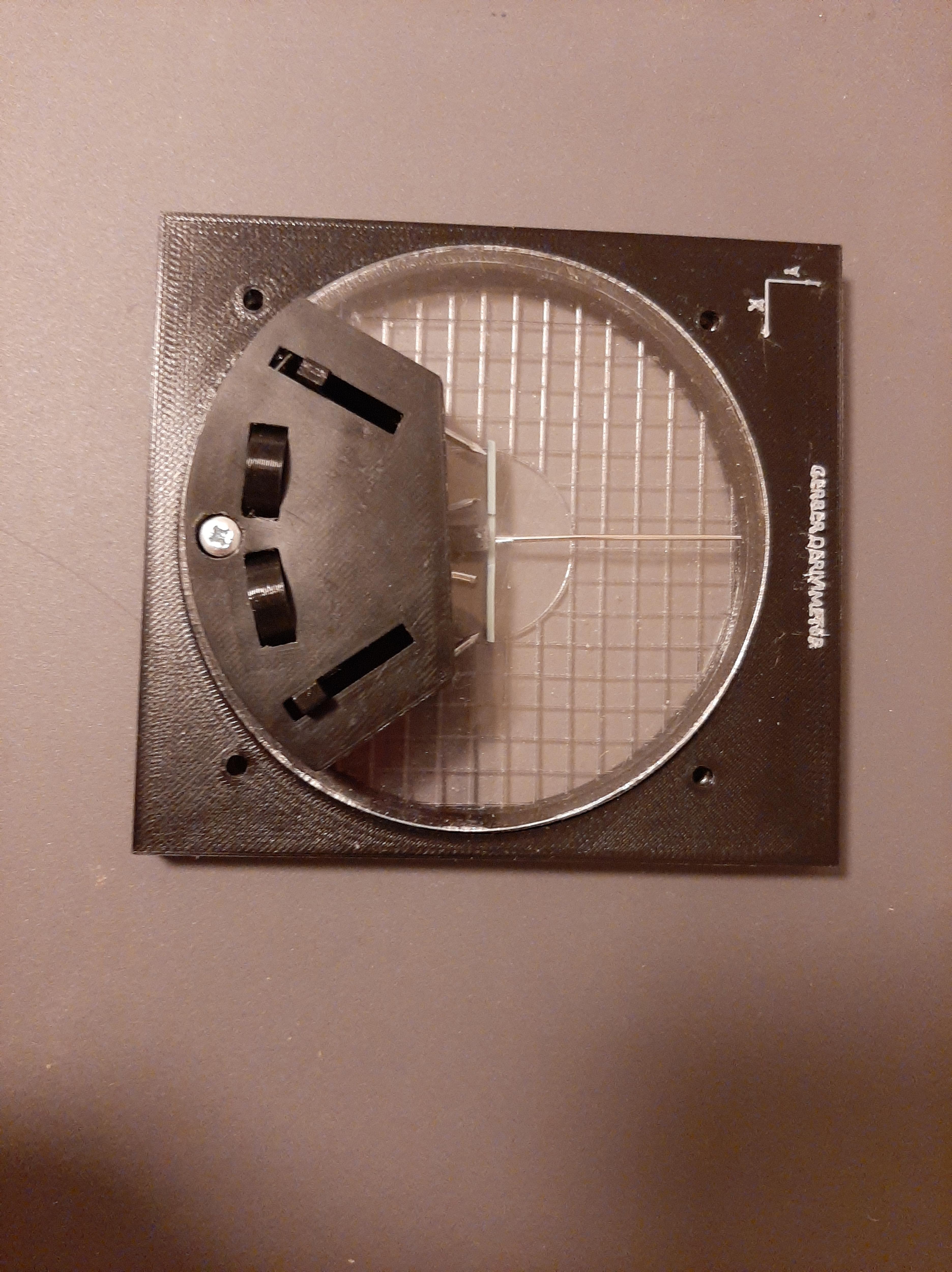
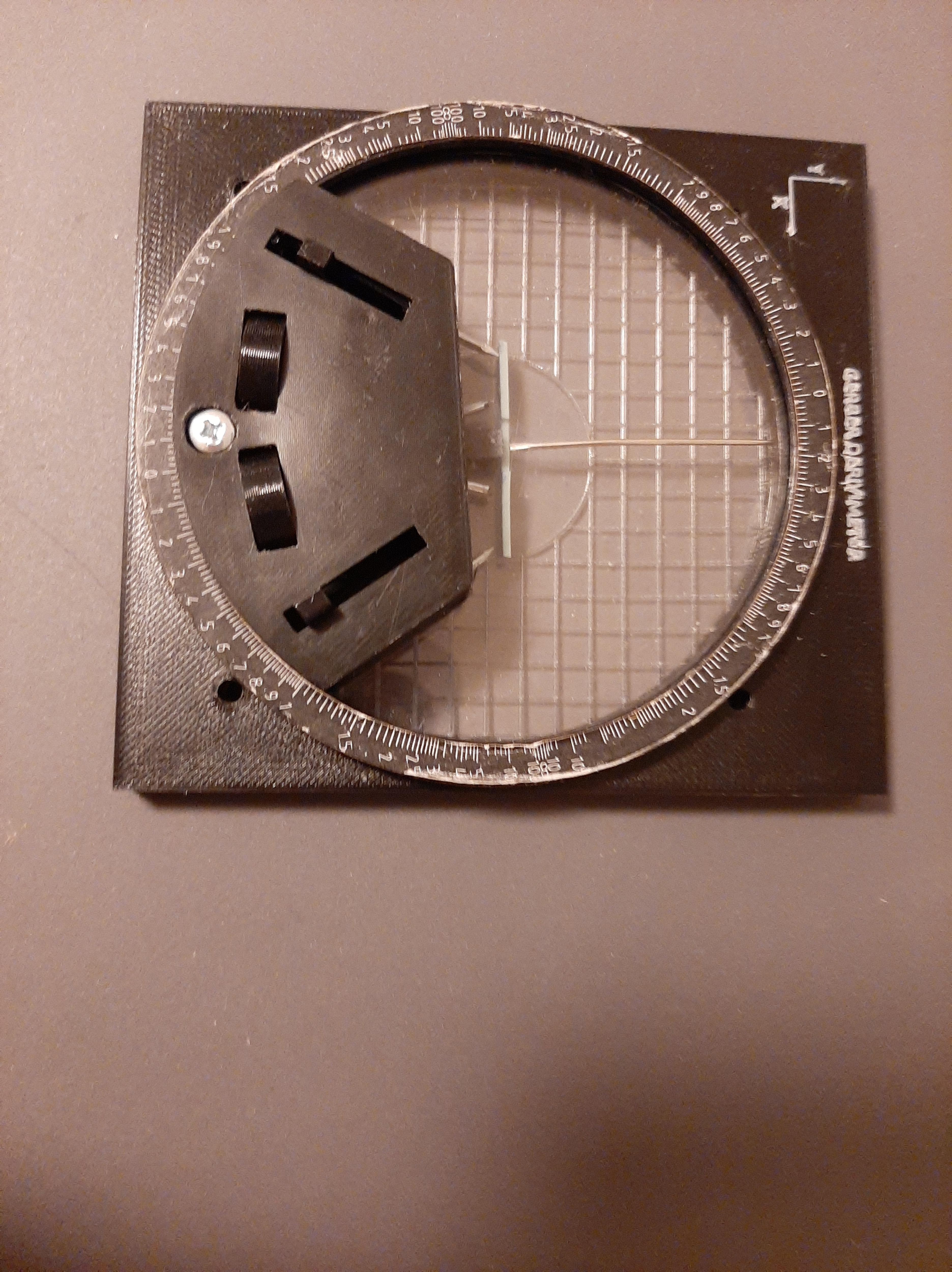
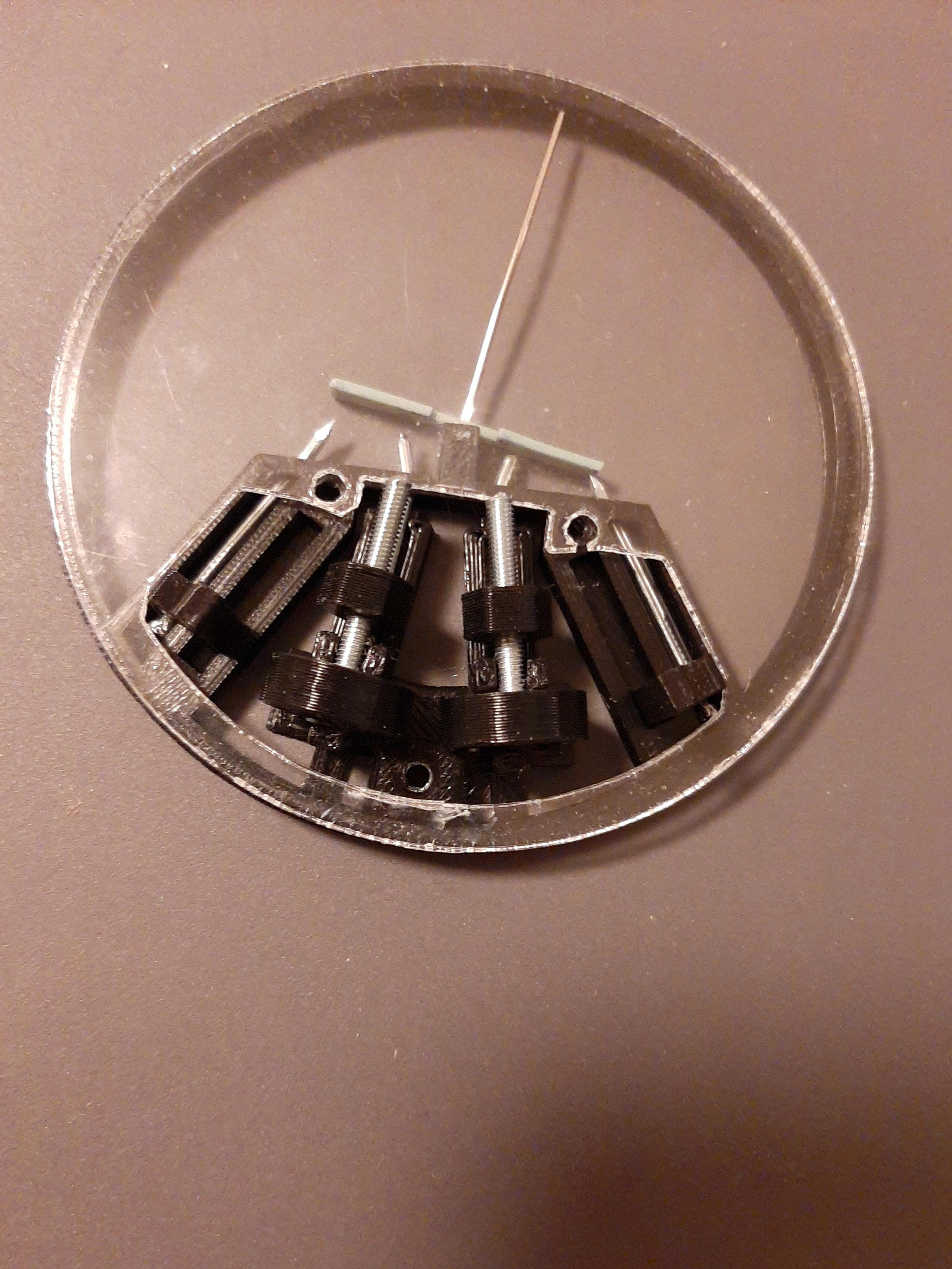
Place the Central Ring with the attached components in the Frame, on top place the outer ring. Prepare the ring holders, by taking a screw, inserting a washer and then a "Side Hold". Once all four are prepared place one in each hole, and screw them. Don't tighten them yet. You need to do a calibration.
Calibration
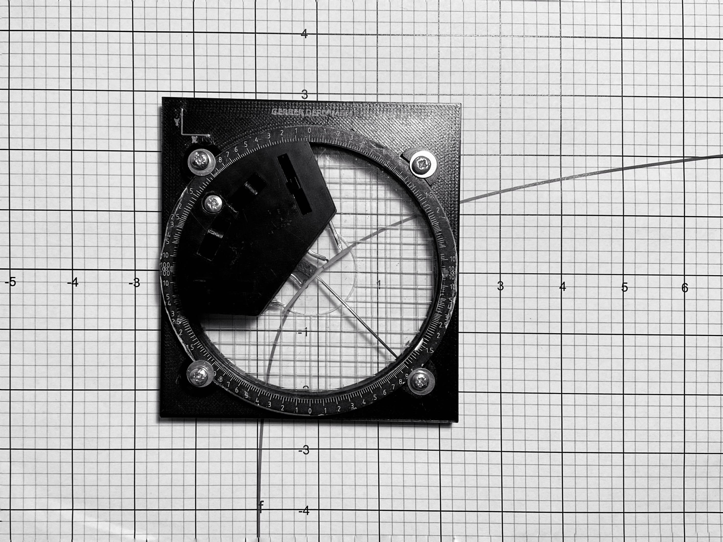
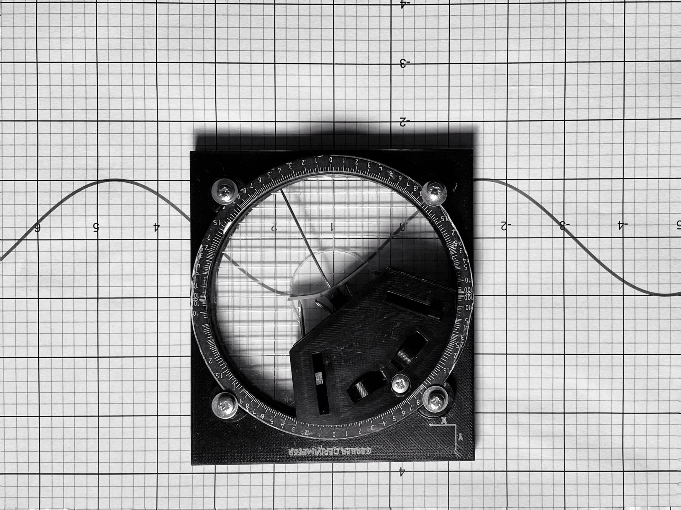
Prepare a straight line on your squared paper. Place the Tool so that the centre is on the straight line. Adjust the side pointers so that the strip follows the line, once it does, rotate the "Outer Ring" so that the pointer points at exactly 0. Then tighten the outer screws prepared in the previous step so that the Outer Ring does not move.
You might need to do further calibration on curves, after a few adjustments everything should be set for use.
You are done, now test it!
Files
All files are listed here. Both the .stl and SketchUp files have all parts included (For printing the .stl file needs to be split into objects).