The Basics of Design and Fusion 360 CAM for CNC Routing
by TheMakerMachine in Teachers > University+
8197 Views, 25 Favorites, 0 Comments
The Basics of Design and Fusion 360 CAM for CNC Routing
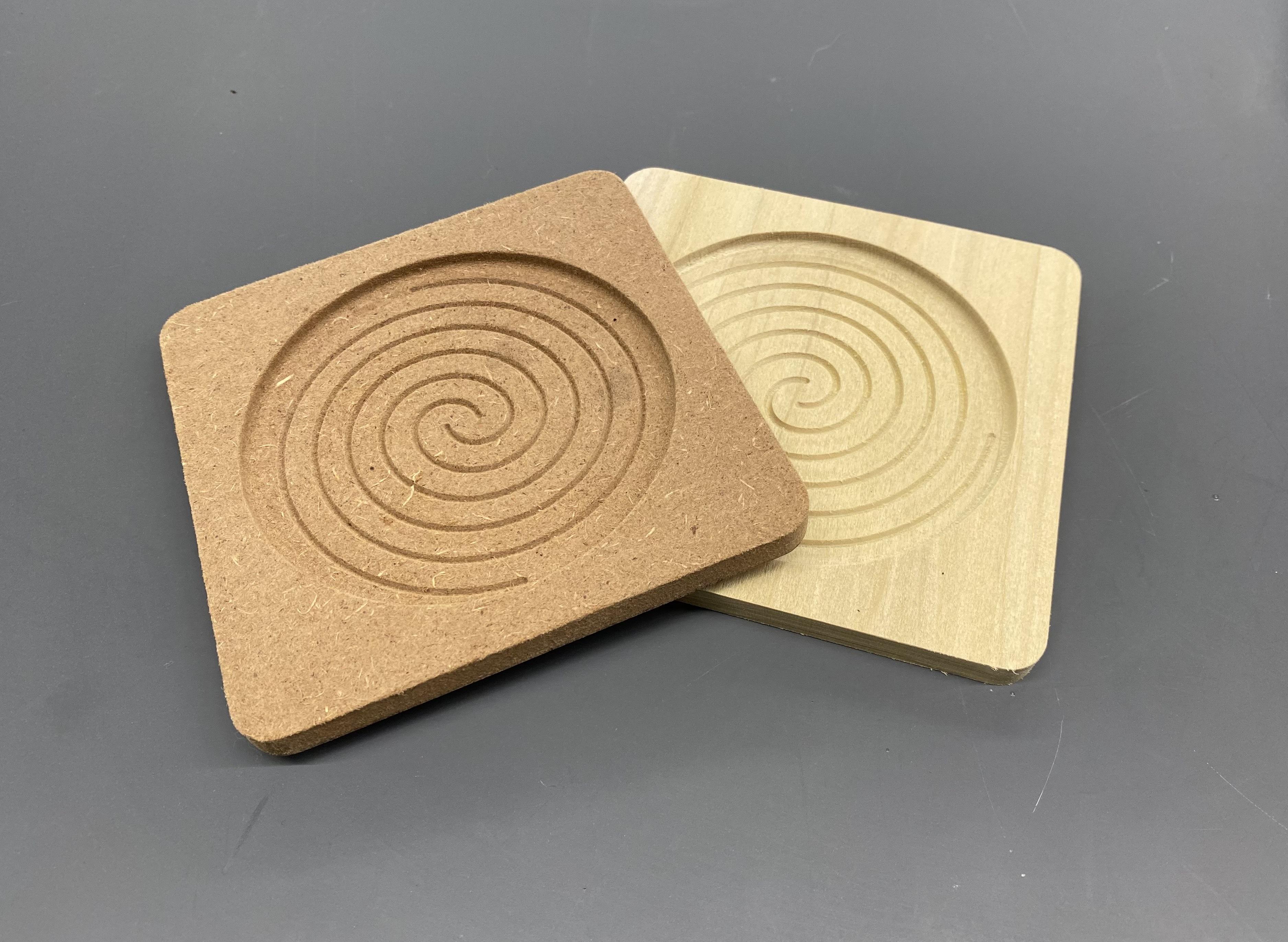
Even though CNC routing and milling has a higher learning curve than other fabrication methods, with structured introductory tutorials and copious resources, students can learn how to make their own parts on a CNC router and hopefully they also realize that 3D printing is not the answer to everything!
The goal of this tutorial is to give teachers and students the tools to create 2D toolpaths using the Fusion 360 Computer Aided Manufacturing (CAM) software and teach the key considerations when designing for CNC routing or CNC milling.
The way I typically teach students in the classroom is to give several very structured projects (like the coasters) using the piece of fabrication equipment before they make something they have designed. CNC routers and mills in particular can be very tricky because they have a much higher cost of failure than a 3D printer or laser cutter. A mistake can cause more expensive damage or even harm a user. However, this should not discourage students or instructors from using the machine because it is an amazing tool! I recommend using cheaper tools (when possible) on student projects, spend extra time double checking their toolpaths, providing one-on-one instruction on machine operation, and being present and observant when they are first operating it on their own.
I've created a video for my students to follow specifically about making the coasters shown in the photo above. This guide will be a little more general however.
https://www.youtube.com/watch?v=sbbUZUCc3aE&t=2s
I am a part time lecturer and makerspace manager at Chapman University in Southern California where our makerspace the Design / Create / Innovate Lab has tons of resources for the Chapman community.
Supplies
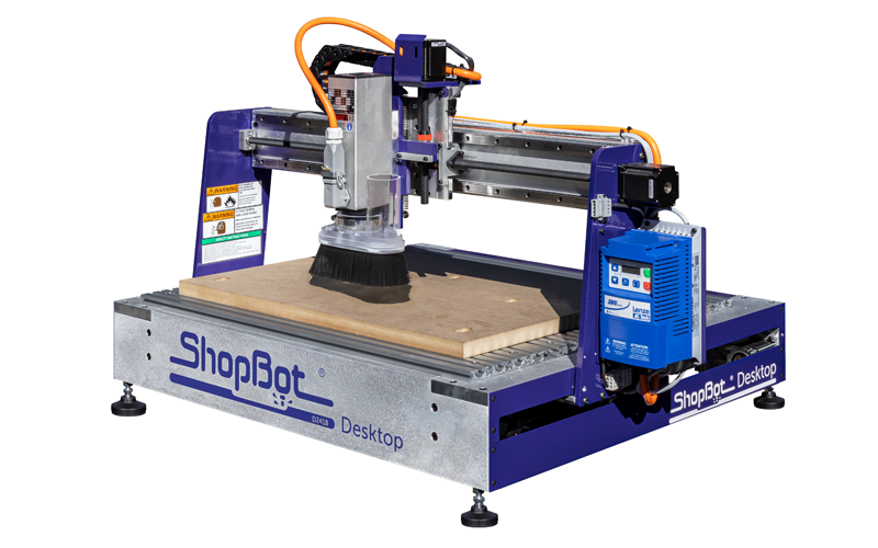
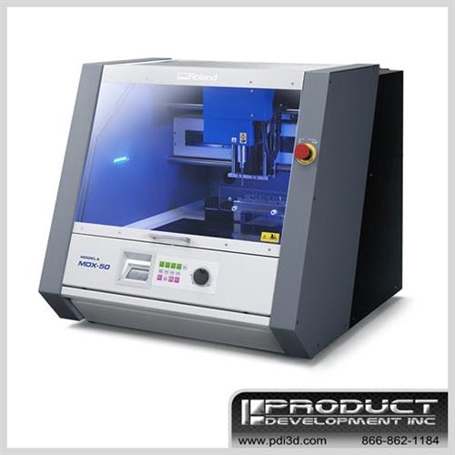
This project is best suited for a space that has access to a CNC router or mill. I have used Fusion 360 CAM with a number a machines including Shopbot routers, Roland mills, and Tormach CNC mills.
I prefer to start students off with a machine that works with softer materials like woods or plastics like the Shopbot or Roland machines to understand the basics of CNC before moving onto a metal CNC mill.
2D CAM Overview
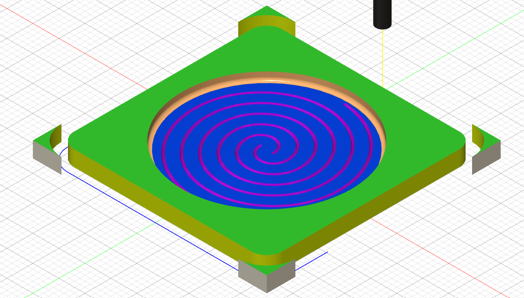
What is CAM?
CAM stands for Computer Aided Manufacturing which the software used to convert your 3D model or mesh into a toolpath or gcode that a CNC (Computer Numerical Control) machine can read. Even a 3D printer slicing software is a CAM software because it converts your STL file into gcode which instructs your printer where to move the nozzle and how quickly and when to extrude. There are different types of CAM software that will do the same for CNC milling or turning and these instruct the machine where and how quickly to move the tool to cut away material. Unfortunately these CAM software can have a higher learning curve than a 3D printer slicer because there is a lot more variability in types of tools and materials in subtractive manufacturing.
Many machines may come with their own CAM software that may be easier to use. For example, Roland has its own software SRP player and many Shopbot users create toolpaths VCarve. However, Fusion 360 CAM offers some key advantages that make it worth the higher learning curve.
- Accessibility of the software
- other software may not be free or may not work on multiple operating systems
- CAD to CAM workflow
- CAD = Computer aided design or 3D modeling, this is what Fusion 360 is most known for
- Because both the CAD and CAM are in the same software, you can make a change to one dimension in your CAD and you only have to regenerate your toolpath to make that change. If they were in different software, you would have to export and import and choose all your settings again which can be a pain.
- More control in toolpath creation
- Although the number of options can be overwhelming at the start, you will have a lot more control in how you want your part to be cut.
- This also is a great first step into metal CNC milling which typically uses complex CAM software like Fusion 360 or Mastercam
What are 2D Toolpaths?
The name may sound confusing but you can create 3D objects using only 2D toolpaths. All this means is that the profiles that the tool will follow are 2-dimensional. This tutorial will not cover 3D toolpaths for example a flower popping out of wood.
2D CAM Overview
The different parts of Fusion 360 CAM we will cover in this tutorial are:
- Tool libraries
- Setup
- Face
- 2D Pocket
- 2D Contour
- Trace
- Post Process
- Fixing issues
I have attached a pdf guide that serves as a reference for students when they have some of the basics down but it won't cover everything in this tutorial.
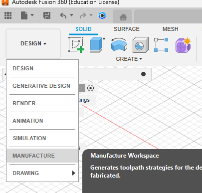
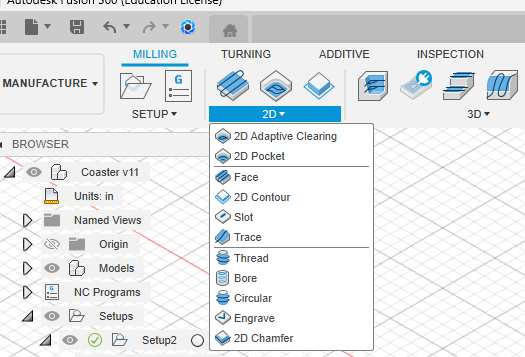
To get to the CAM portion of Fusion 360, select the Design dropdown in the top left corner and change to the Manufacture workspace.
Downloads
Tool Libraries
What are tool libraries?
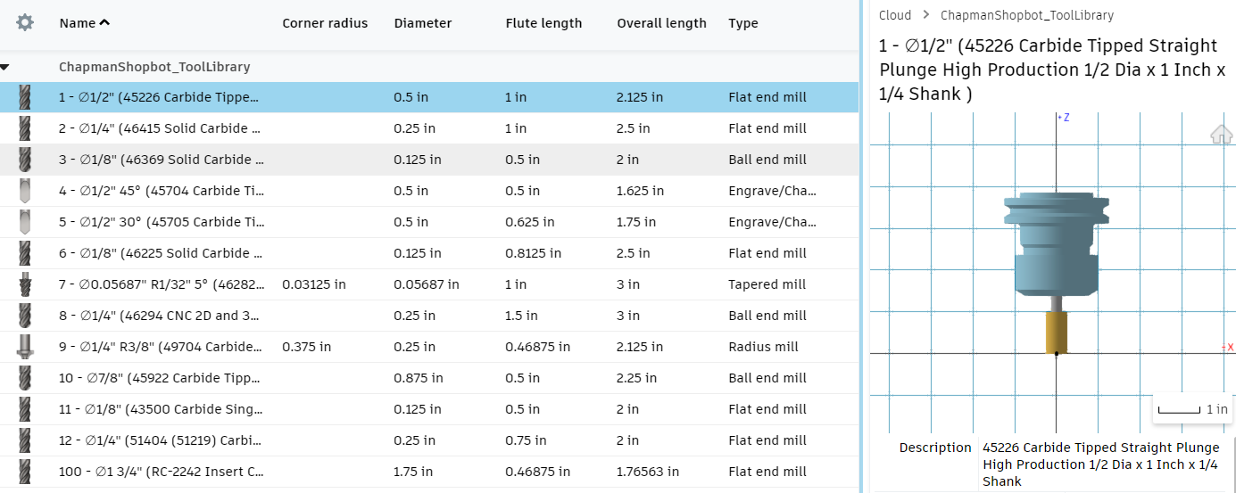
Tool libraries are a great feature of Fusion 360 that allows users to create certain tool presets and save them to be reused in different files. One advantage for instructors is that you can share a tool library with students that has all the feeds and speeds associated with the actual tools you have in your space. This takes a lot of the room for error away from students.
I won't cover too much on how to create a tool library but check out this video to see more about how to make one. Deciding the correct feeds and speeds can be very tricky and there is a lot of math that is needed to be super precise. But the great thing about working with soft materials (woods, plastics) in a non-production setting is that you don't need to be perfect. You can slow everything down a bit and be a little less aggressive with material removal. For our Shopbot, I will typically buy bits from Amana tools like this 1/2" tool where I can find the data sheet that will give me recommended speeds and feeds. If it feels like it needs adjustment, then I will edit the numbers a little.
Types of Tools
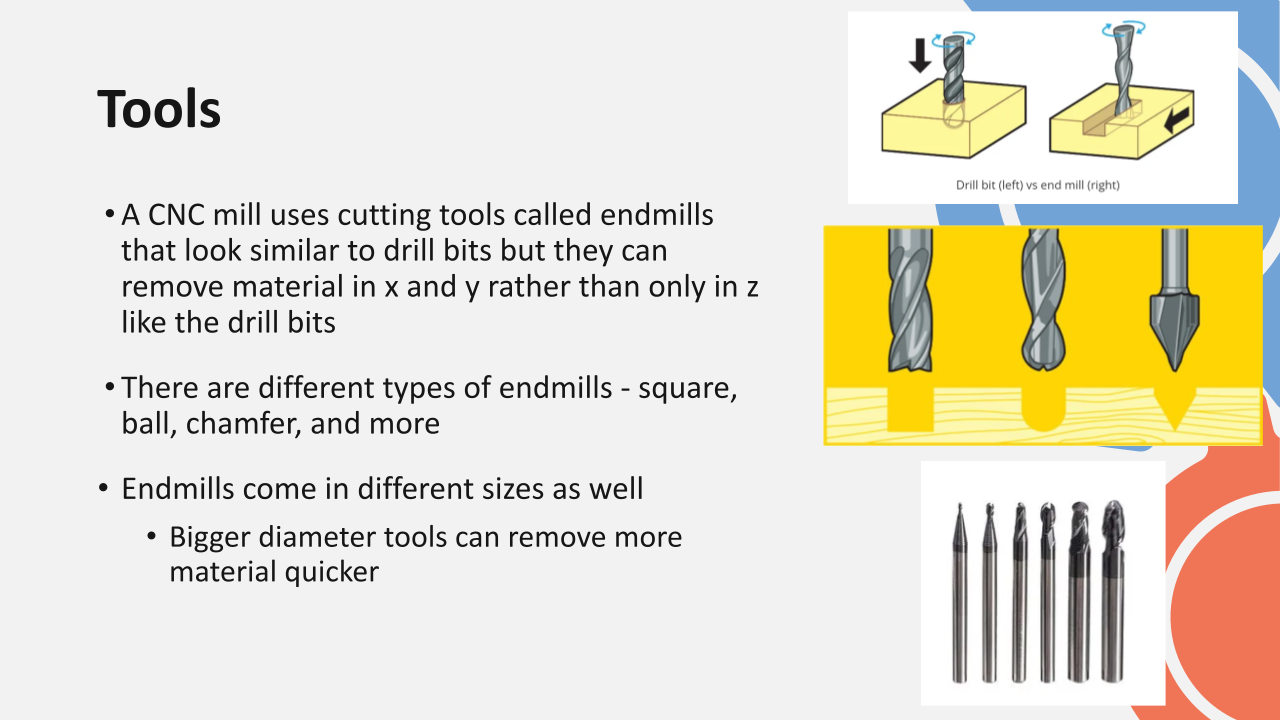
A CNC mill uses cutting tools called endmills that look similar to drill bits but they can remove material in x and y rather than only in z like the drill bits. The most common types of endmills are square (flat bottom) and ball (rounded bottom) endmills that can create different geometries when cutting.
How to import a tool library
I've attached several of the tool libraries I have created for machines in our makerspace. The settings are by no means perfect and may need adjustment for use on other machines.
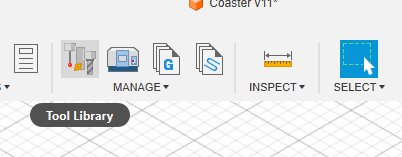
- Select the Tool Library button above the Manage drop down while in the Manufacturing workspace.
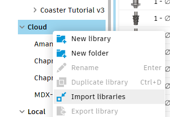
- Right click on Cloud libraries and select Import Libraries
- If you don't see the cloud option, close the window, select your account (top right) > Preferences > Manufacture and check Enable Cloud Libraries - see the linked video above for a clearer guide
- You should then be able to see all the tools in that library as well as its information
Setup
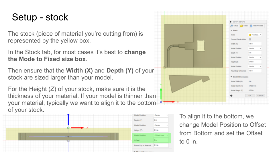
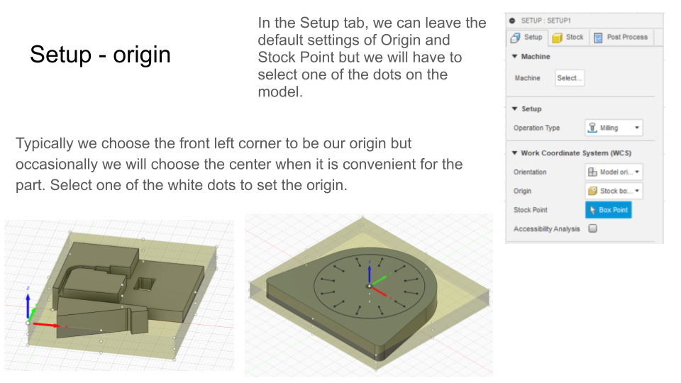
The first thing you are going to do in the Manufacture workspace is create a Setup.
The setup defines two important things,
- the size of your stock - the piece of material you are cutting your model out of
- your origin - the location of your stock that we are defining as zero
To create your setup:
- Select Setup in the top left corner next to the Manufacture tab
- In the Stock tab, I typically change the mode to Fixed size box
- I will also make sure my Width (X) and Depth (Y) are larger than my model
- If the Height (Z) of the stock is thicker than my model then I will align it to the bottom
- To align it to the bottom, we change Model Position to Offset from Bottom and set the Offset to 0 in.
- In the Setup tab, you can select the Origin to be on one of the edges or center of the stock
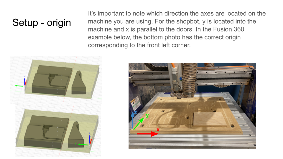
- I recommend placing it in a corner and knowing which corner that is when you place it in the machine
- It is really important to pay attention to the direction of the axes to make sure you are orienting it in the machine correctly. Check on your machine which size is x and y.
Most Common 2D Toolpaths
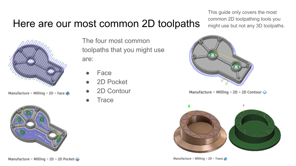
The four common toolpaths we will cover in this guide are:
- Face
- 2D Pocket
- 2D Contour
- Trace
These can all be found in the 2D dropdown in the Manufacture workspace under the Milling tab.
Face
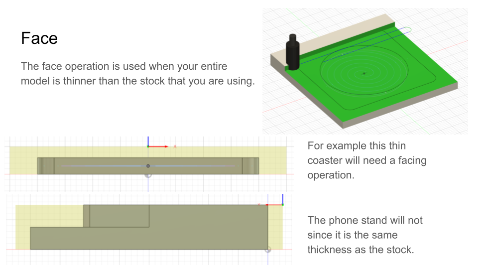
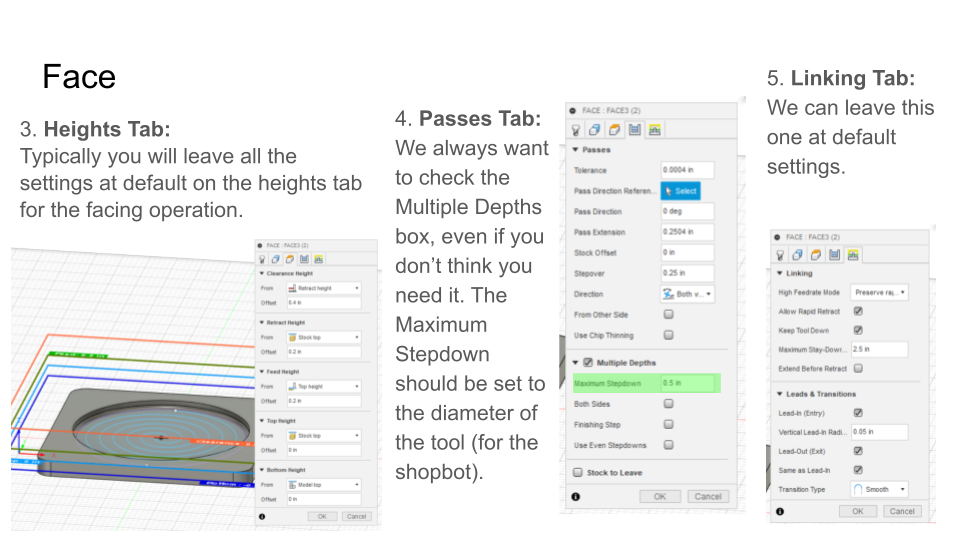
The face operation is used when your entire model is thinner than the stock that you are using. Not all models will need the face operation.
Under the 2D dropdown, select Face. There are several settings to change in most tabs:
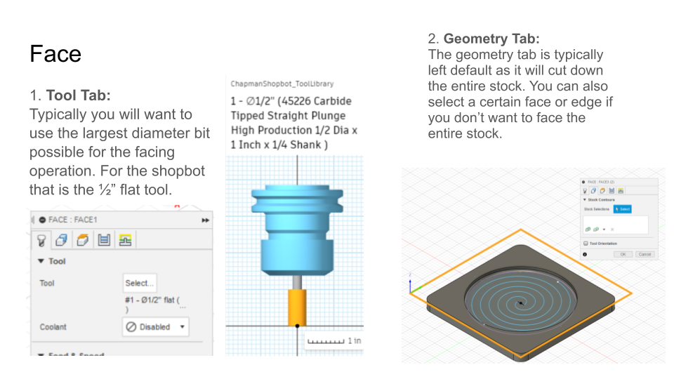
- Tool Tab: Typically you will want to use the largest diameter bit possible for the facing operation. For the shopbot that is the ½” flat tool. Use the select option to pick from your tool library.
- Geometry Tab: The geometry tab is typically left default as it will cut down the entire stock. You can also select a certain face or edge if you don’t want to face the entire stock.
- Heights Tab: Typically you will leave all the settings at default on the heights tab for the facing operation.
- Passes Tab: We always want to check the Multiple Depths box, even if you don’t think you need it. The Maximum Stepdown should be set to the diameter of the tool (for the shopbot).
- When you are removing a large thickness of material, you almost always want to take it off in several layers. If you try to remove too much, you can break the tool or cause the material to shift.
- Linking Tab: We can leave this one at default settings.
In the toolpath settings, there is always so many options which can be very overwhelming at first. The key is to learn which you can ignore until you actually need to change it.
2D Pocket
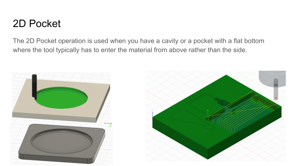
The 2D Pocket operation is used when you have a cavity or a pocket with a flat bottom that doesn't go through the bottom of the material where the tool typically has to enter the material from above rather than the side.
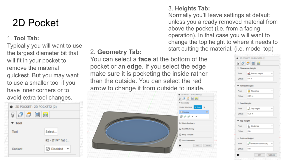
Under the 2D dropdown, select 2D Pocket. There are several settings to change in most tabs:
- Tool Tab: Typically you will want to use the largest diameter bit that will fit in your pocket to remove the material quickest. But you may want to use a smaller tool if you have inner corners or to avoid extra tool changes.
- Geometry Tab: You can select a face at the bottom of the pocket or an edge. If you select the edge make sure it is pocketing the inside rather than the outside. You can select the red arrow to change it from outside to inside.
- Heights Tab: Normally you’ll leave settings at default unless you already removed material from above the pocket (i.e. from a facing operation). In that case you will want to change the top height to where it needs to start cutting the material. (i.e. model top)
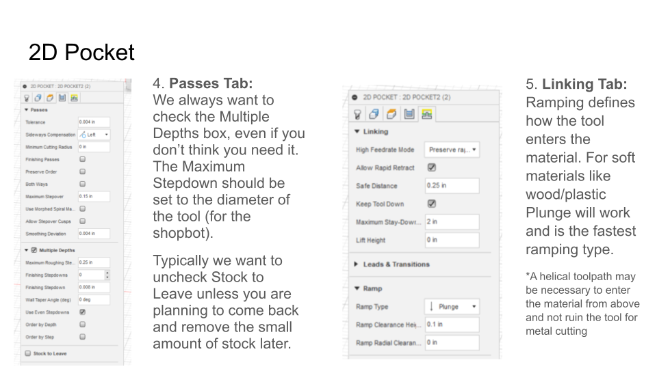
- Passes Tab: We always want to check the Multiple Depths box, even if you don’t think you need it. The Maximum Stepdown should be set to the diameter of the tool (for the shopbot).
- Typically we want to uncheck Stock to Leave unless you are planning to come back and remove the small amount of stock later.
- Linking Tab: Ramping defines how the tool enters the material. For soft materials like wood/plastic Plunge will work and is the fastest ramping type.
- A helical toolpath may be necessary to enter the material from above and not ruin the tool for metal cutting
2D Contour
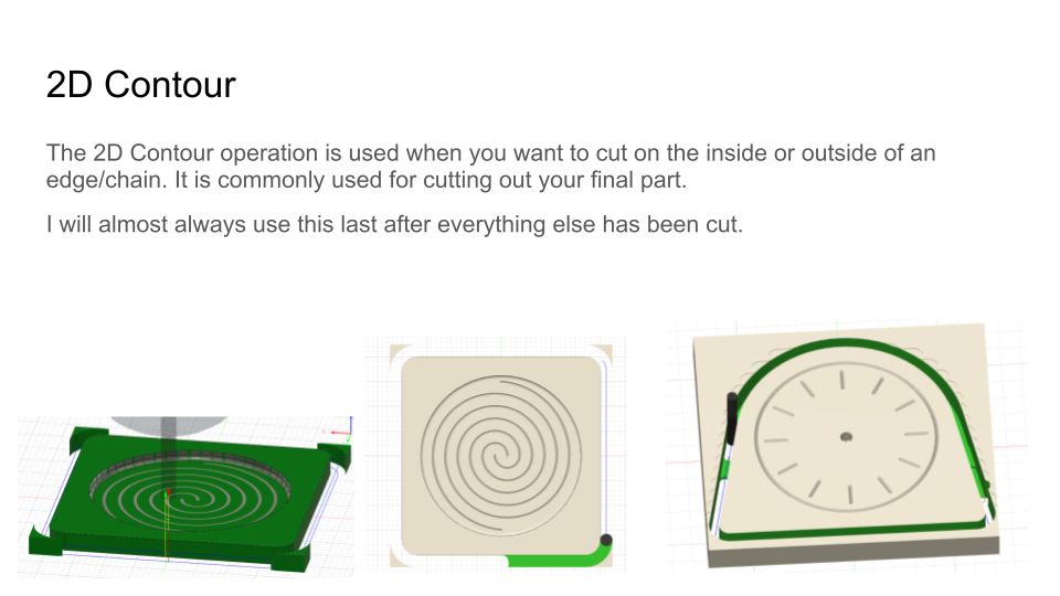
The 2D Contour operation is used when you want to cut on the inside or outside of an edge/chain. It is commonly used for cutting out your final part. I will almost always use this last after everything else has been cut.
Under the 2D dropdown, select 2D Contour. There are several settings to change in most tabs:
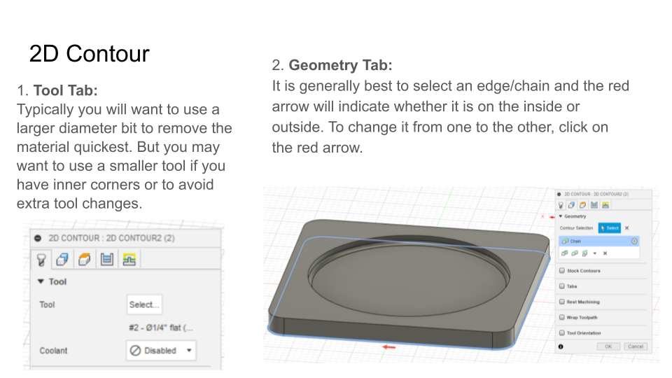
- Tool Tab: Typically you will want to use a larger diameter bit to remove the material quickest. But you may want to use a smaller tool if you have inner corners or to avoid extra tool changes.
- Geometry Tab: It is generally best to select an edge/chain and the red arrow will indicate whether it is on the inside or outside. To change it from one to the other, click on the red arrow.
- If I am not using tape to hold down my stock, I may use tabs on the contour to make sure it does not move around as the part is being cut out.
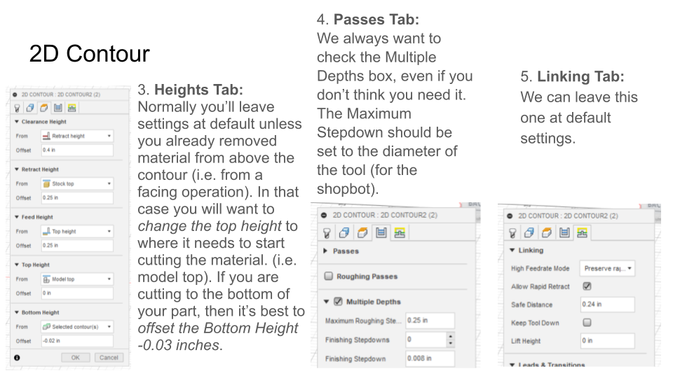
- Heights Tab: Normally you’ll leave settings at default unless you already removed material from above the contour (i.e. from a facing operation). In that case you will want to change the top height to where it needs to start cutting the material. (i.e. model top). If you are cutting to the bottom of your part, then it’s best to offset the Bottom Height -0.03 inches (when you have a spoilboard).
- Typically a CNC router will have a sacrificial piece of material under where you are placing your stock. When you cut all the way through your stock you don't want to cut into the metal base of your machine but instead into that sacrificial material, the spoilboard. We add the offset to make sure it goes all the way through. (Make sure students put the decimal point in the correct place!)
- Passes Tab: We always want to check the Multiple Depths box, even if you don’t think you need it. The Maximum Stepdown should be set to the diameter of the tool (for the shopbot).
- Linking Tab: We can leave this one at default settings.
Trace
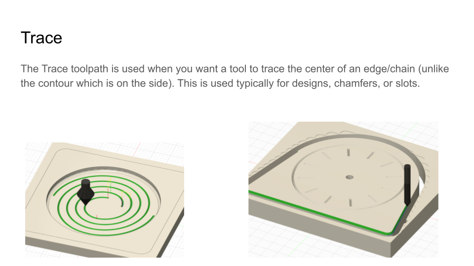
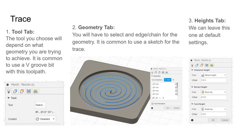
The Trace toolpath is used when you want a tool to trace the center of an edge/chain (unlike the contour which is on the side). This is used typically for designs or slots.
Under the 2D dropdown, select Trace. There are several settings to change in most tabs:
- Tool Tab: The tool you choose will depend on what geometry you are trying to achieve. It is common to use a V groove bit with this toolpath.
- Geometry Tab: You will have to select and edge/chain for the geometry. It is common to use a sketch for the trace.
- Heights Tab: We can leave this one at default settings.
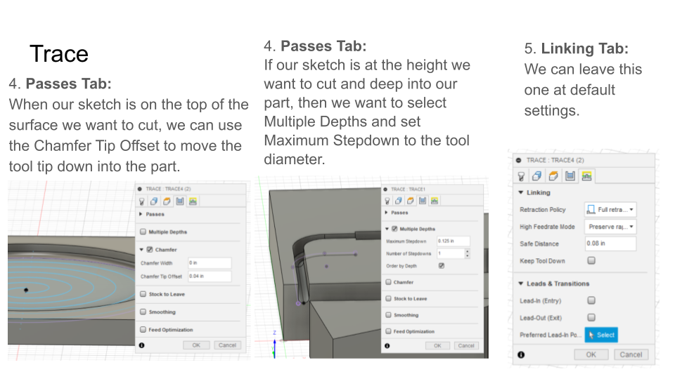
- Passes Tab: When our sketch is on the top of the surface we want to cut, we can use the Chamfer Tip Offset to move the tool tip down into the part.
- If our sketch is at the height we want to cut and deep into our part, then we want to select Multiple Depths and set Maximum Stepdown to the tool diameter.
- Linking Tab: We can leave this one at default settings.
Simulation
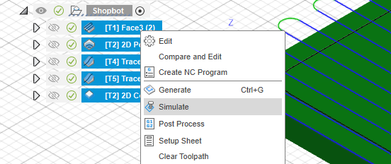
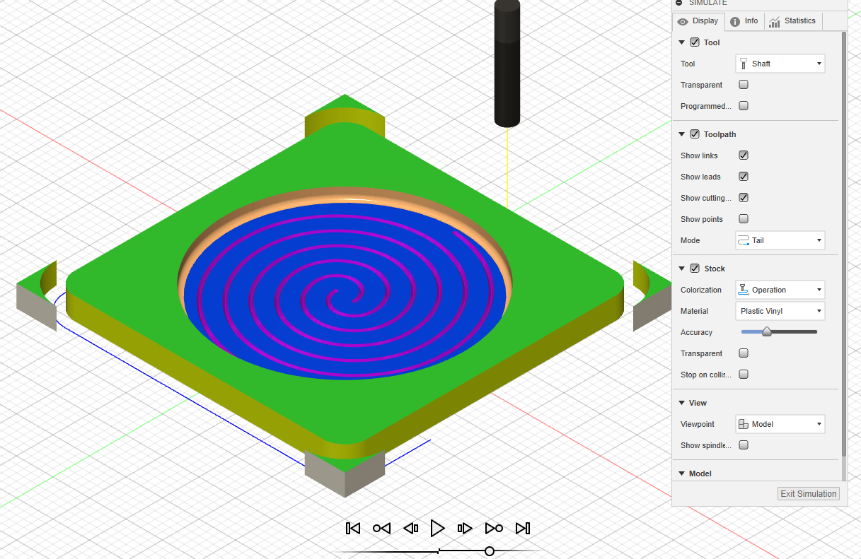
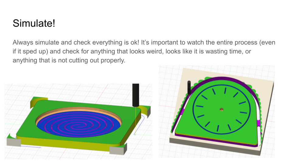
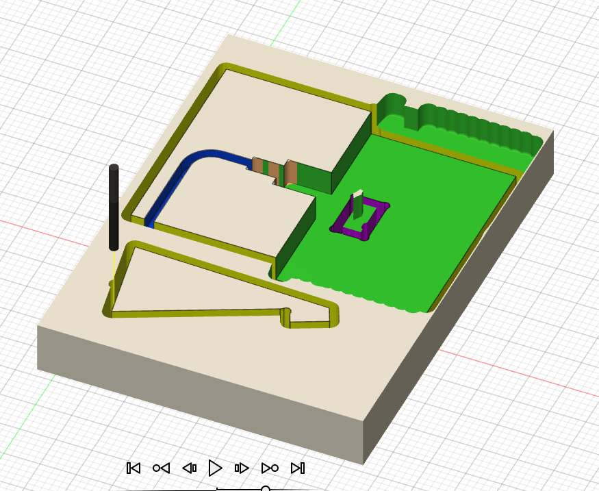
One of the other great parts about the Fusion 360 CAM software is that you can simulate the toolpaths you have made. To simulate, select the toolpath(s) you want to view, right click and select Simulate.
In the Simulate window, I typically change the toolpath mode to Tail and check the Stock box to see how the material is being removed. I will also hide my model sometimes to make it clearer to see what is going on.
You can play, skip between toolpaths, and change the speed with the controls at the bottom center of the screen.
Always simulate and check everything is ok! It’s important to watch the entire process (even if it sped up) and check for anything that looks weird, looks like it is wasting time, or anything that is not cutting out properly. It's much easier to catch mistakes here than on the machine.
Post Process
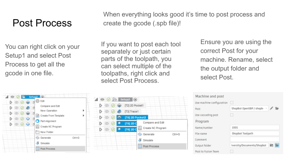
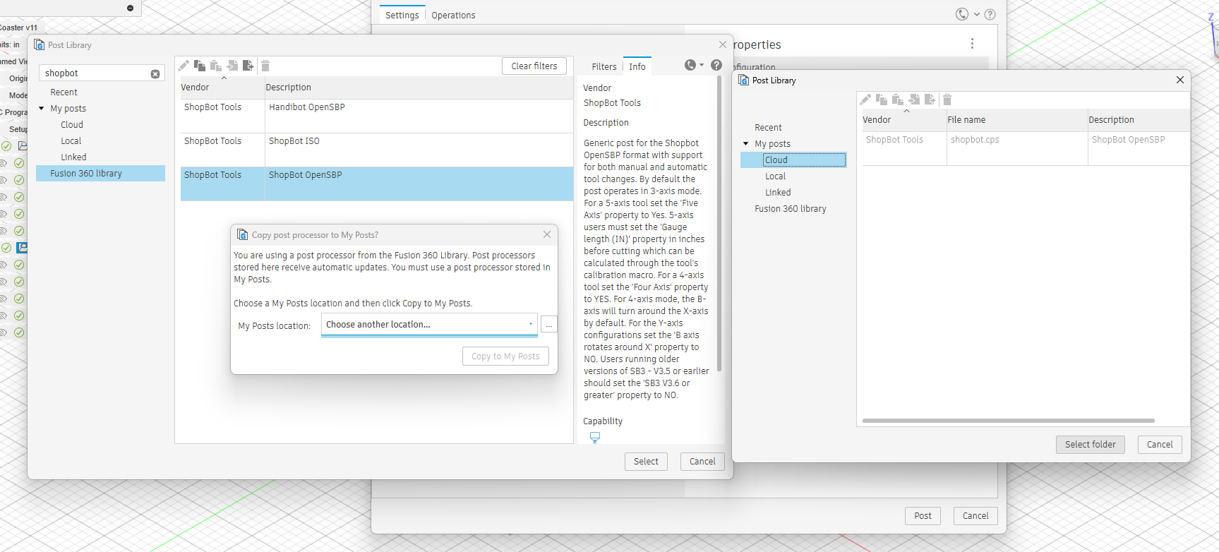
To turn your toolpaths into gcode that can be read by the machine, you will have to post process your toolpath to the specific type of gcode your machine reads.
To post process:
- You can right click on your Setup1 and select Post Process to get all the gcode in one file.
- Alternatively, if you want to post each tool separately or just certain parts of the toolpath, you can select multiple of the toolpaths, right click and select Post Process.
- Select the Post for your machine
- The Fusion 360 library already has many options built in but you can also download some from the internet if you don't find your machine. It makes you go through this weird process where you have to copy the post from the Fusion 360 library to your local posts library. Follow the prompts from the dropdowns to copy it.
- Make sure you select your desired folder and name it something unique. You may be posting multiple times if your part fails the first time.
Tip: If your part does not cut out exactly as you had hope (i.e. not cut all the way through or a hole is not big enough) and you haven't taken it out or moved it at all in the machine, you can make the edits in your file and post just the necessary toolpath and run it again (without rezeroing).
Fix Issues With Feeds and Speeds
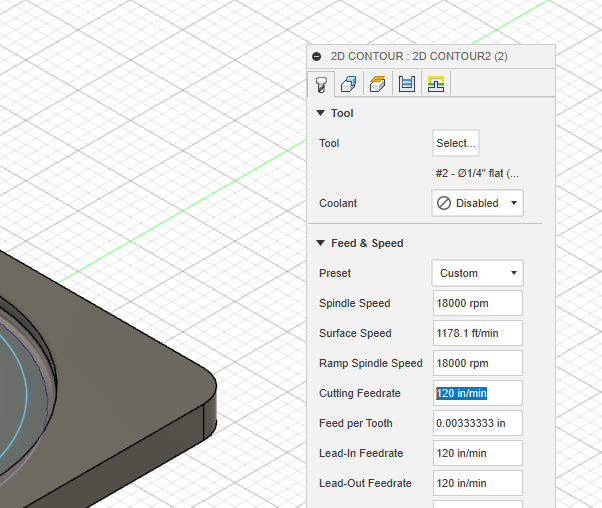
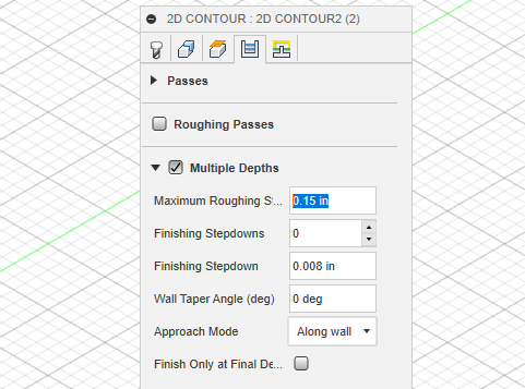
If your cuts are too aggressive and it is causing the part to come off the bed there are a couple of easy changes you can make to your toolpaths to reduce that chance. However you may also need to look at your fixturing and make sure it is solidly on there. I most often have issues with the 2D contour because it is usually removing an entire tool's width of material unlike a face or pocket operation.
Toolpath changes:
- Reduce the feedrate - in the Tool tab I will reduce the Cutting Feedrate by almost half to slow the tool travel speed when cutting
- Reduce the stepdown - in the Passes tab, I will reduce the Maximum Roughing Stepdown to reduce how much material is being removed in each layer
These typically will help a lot with reducing the chance of failure.
Designing for CNC Routing / Milling
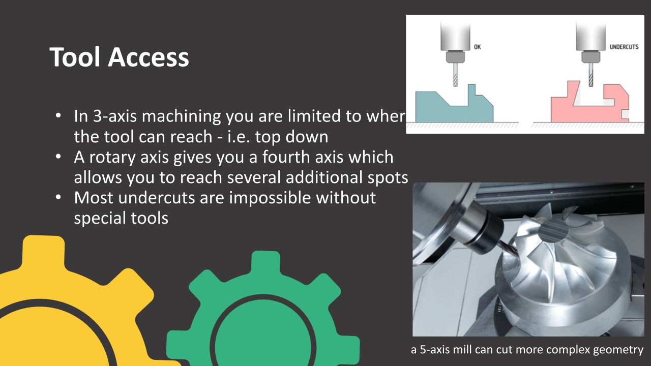
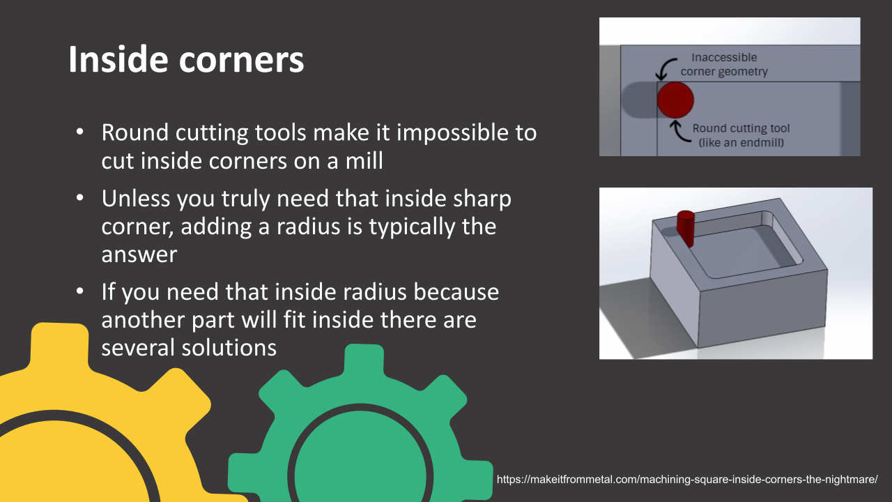
Designing for CNC routing or milling is a pretty complex topic but there are some key points that students should know to get started. CNC milling has certain limitations which can vary from machine to machine, but the main ones to think about are:
- Size of your material
- Most material used in CNC routers are sheet goods so parts should be designed with the size of material they are being cut out of in mind
- Inside corners
- Endmills and other tools are round so you cannot get sharp inside corners, there are several workarounds to that - please take a look at the attached slides to learn about some
- Fixturing
- Cutting puts so much force on the material that how it is held down is very important and you may want to consider that in your design. You could choose to model in some tabs in some cases.
- Tool access
- With 3 axis milling, most overhangs are not possible to cut because the tool will never be able to reach them.
Downloads
Video Resources
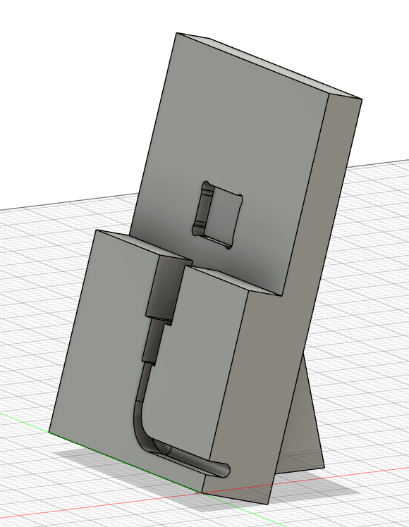
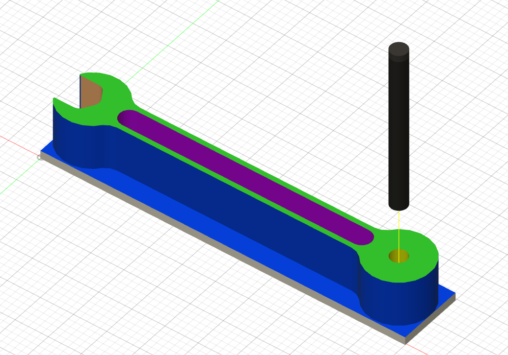
Written tutorials for software like Fusion 360 can be hard to follow because it is difficult to describe every option to click so I have also made several video tutorials for students involving Fusion 360 CAM as well as some of machine operation to cut out the part.
- Coasters on the Roland MDX-50
- Video on Roland Machine Operation
- Coasters on the Shopbot
- Video on Shopbot Machine Operation
- Phone Stand CAD and CAM on the Shopbot
- Wrench Business Card Holder on the Tormach
- Video on Tormach Machine Operation
Thank you for reading and I hope this guide and these resources are useful to you in your classroom or with your personal projects. Please reach out if you have any questions and I will do my best to answer them.