The Arduino CNC Drawing Machine | 2d Plotter | How to Make Arduino 2d Plotter Cnc Machine
by vishnu_ in Circuits > Arduino
20558 Views, 148 Favorites, 0 Comments
The Arduino CNC Drawing Machine | 2d Plotter | How to Make Arduino 2d Plotter Cnc Machine
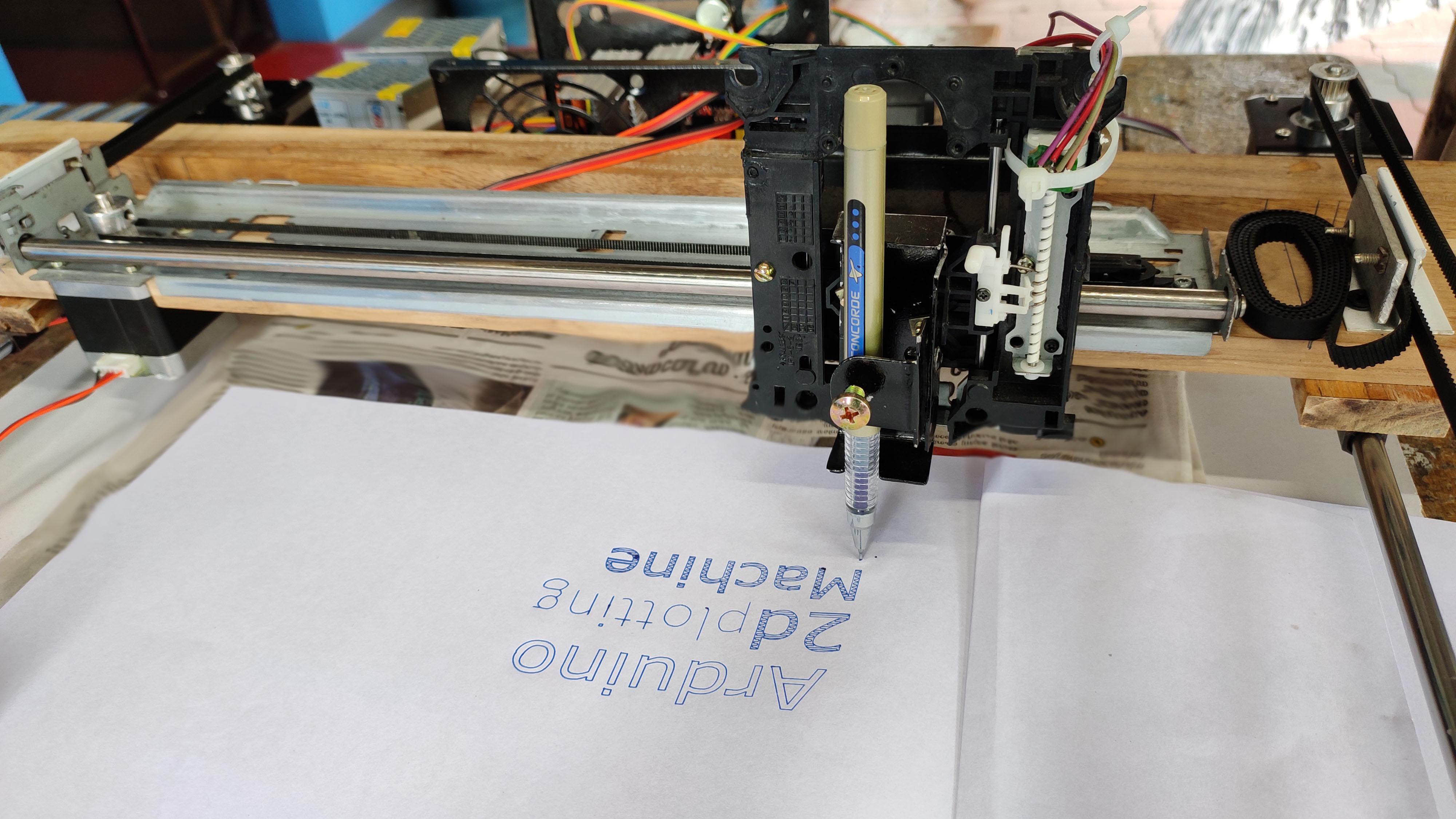
Hi guys, so this instructable will help you out to make simple, less budget Arduino cnc plotter.
In this project i had used some recycled parts like printer rail, smps box cd drive mechanism etc..
so the supplies that you should buy are less and less in cost too.
I was very curious about all these kind of stuff so that i had started building this project couple of months before. well i thought i can draw the school records using this great 2D machine. This instructable will cover almost all the area to build a high quality cnc machine.
Firstly I will step into building the mechanical setup of the cnc machine. I had used Fusion 360 to express my idea into reality in making this project. Since i am using Fusion 360 for first time, I took lots of time in designing some of the parts. I have given the resultant model below.
Coming back to the software and hardware parts, I had used Arduino UNO ,which acts as motherboard for this project. Used grbl v1.1h. I will give a detailed explanation on about how to load firmware, creating custom G-Code, handling the user friendly G-Code Sender.
And you can use this machine to draw birthday cards, record drawing works,writing letters,decorating pages with your own ideas...... :).
Sorry for the mistakes in sentence, if any.....
Intro Video

Video Link : https://www.youtube.com/2d plotter
This video shows the working of this machine after all the parts has finished it built. I put just for an introduction. If you would like to watch, just take a quick look and come back we shall start with following steps. :)
Transforming Idea Into Reality: Fusion 360
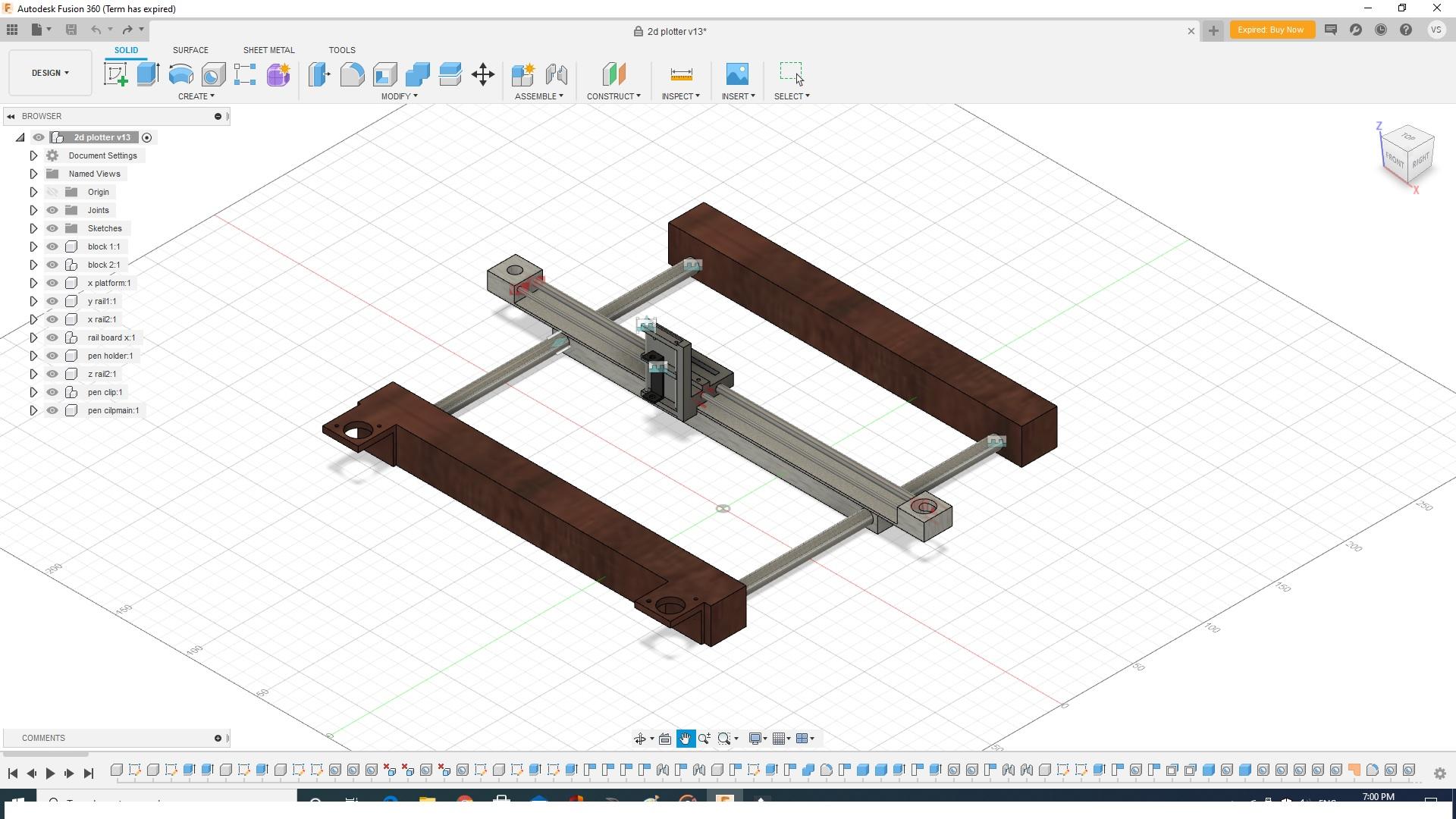
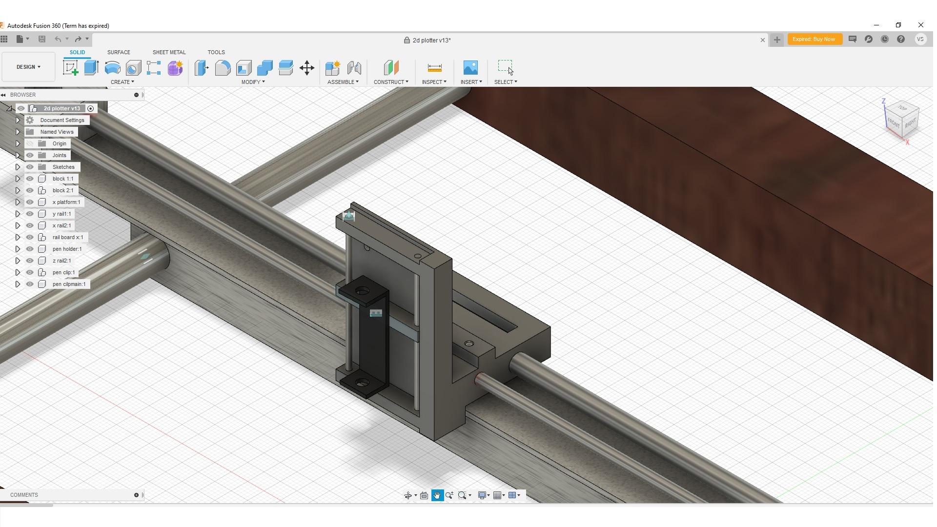
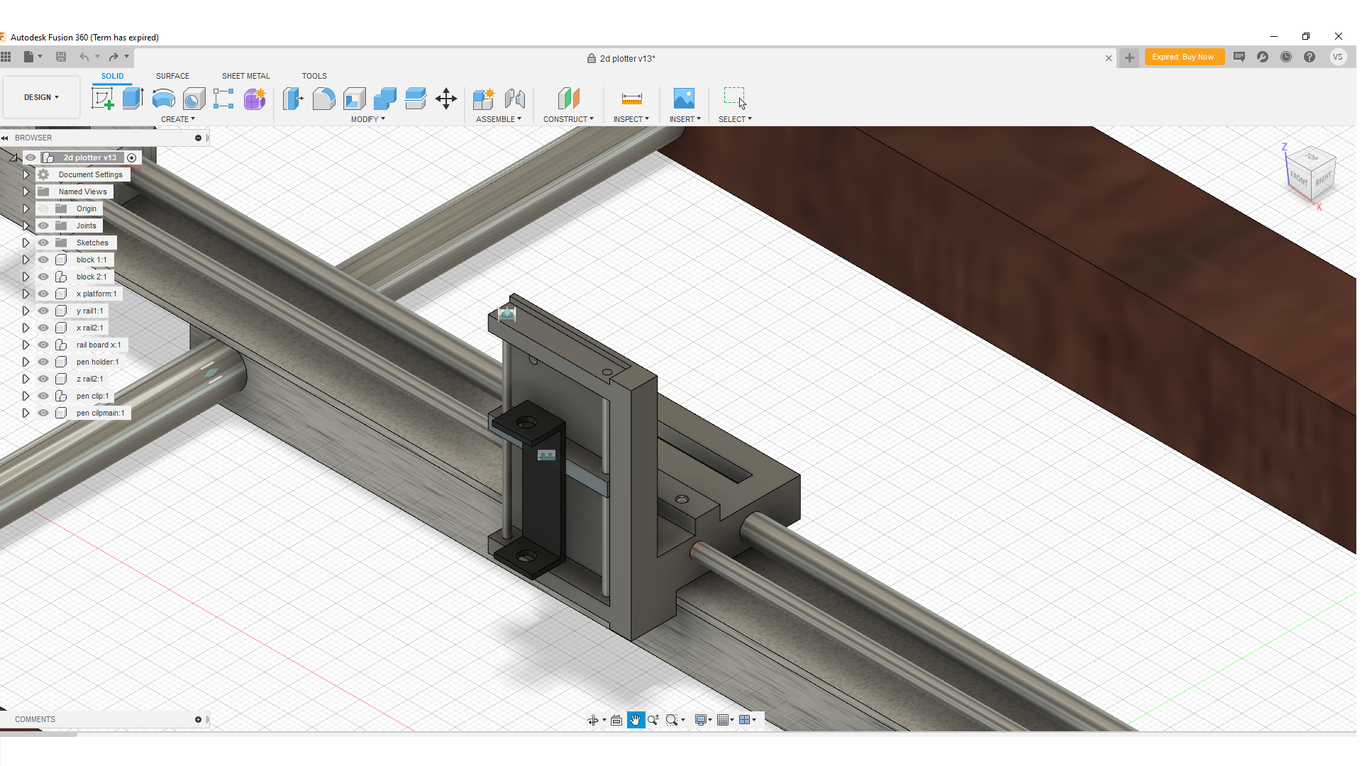
Well, i have expanded my idea using fusion 360 software. Watch the video to know the outline of this project.
since i am using for first time, Only able to design some parts here. But i am sure this is a best application for beginners.
Introduction to the Parts
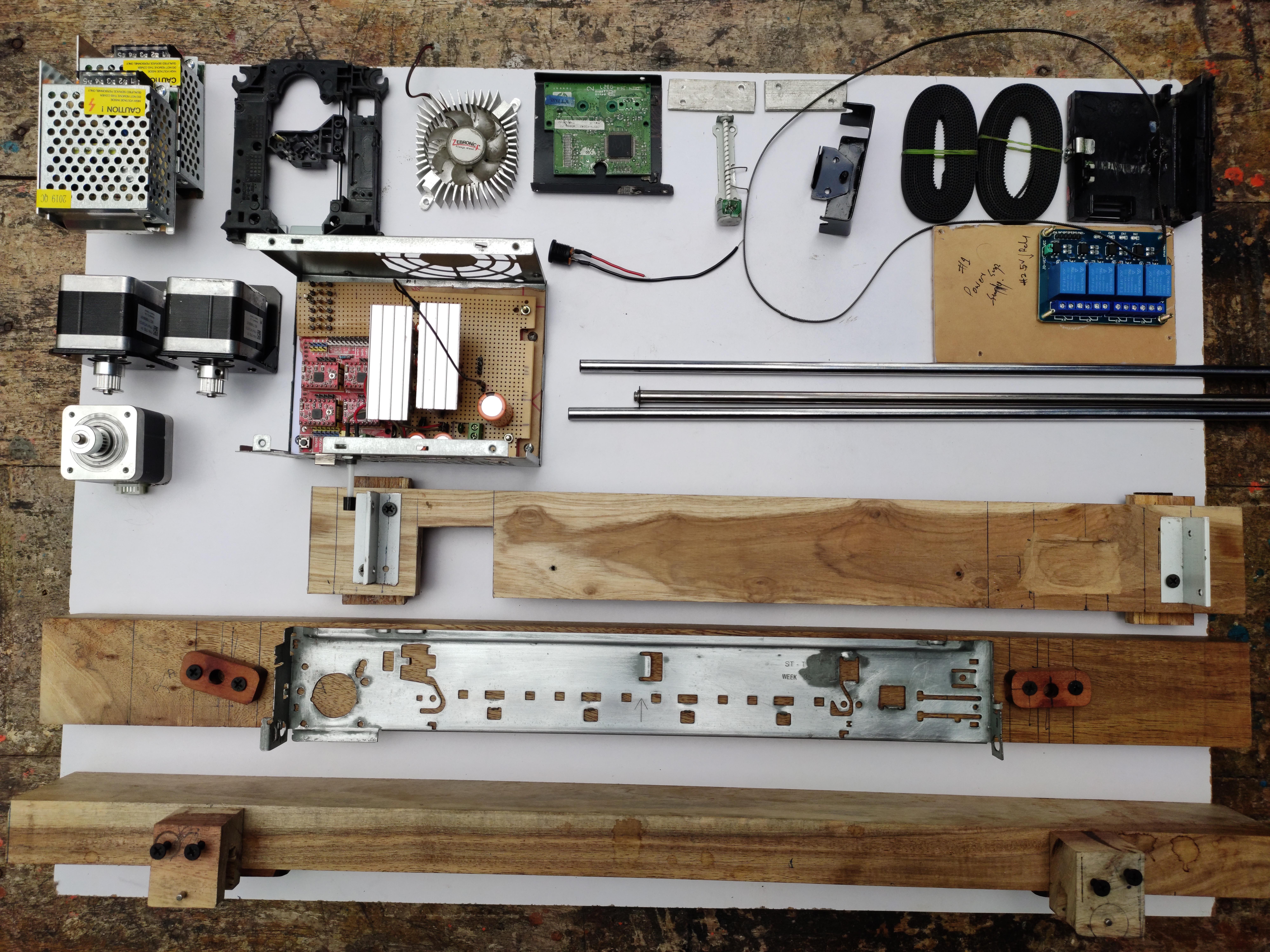
Hardware Parts:
- Nema 17 Stepper Motor x3 https://www.amazon.in/INVENTO-Bipolar-Stepper
- Arduino Uno x1 https://www.amazon.in/DS-Robotics-ATmega328P-Compatible-ATMEG16
- Mounting L Brackets for Nema 17 x2 https://www.amazon.in/gp/product/B07GTH
- A4988 Stepper Motor driver x4 https://www.amazon.in/Microbot-StepStick-Stepper-Heatsink
- CNC Expansion shield (A4988 compatible) x1 https://www.amazon.in/Engraver-Shield-P
- CHPSS535 Idle Pulley x2 https://www.amazon.in/3D-Innovations-CHPSS535-Pulley-Sy
- GT2 timing belt x2 of 2m each https://www.amazon.in_atf_
- Smooth rod 0.5m x2 https://www.amazon.in/gp/produ
- GT2 Pulley, 20 Teeth, 5mm Bore for 6mm Belt x3 https://www.amazon.in/INKJET-Tim
- DVD stepper motor x1 https://www.amazon.in/Nktronics-Stepper-Mot
- 12v 2A Power supply x2 https://www.amazon.in/SunRobotics-Industrial-Application-Prin
- some connecting/normal wires https://www.amazon.in/Rainbow-Testing-Electric-Science
- data cable for arduino x1 https://www.amazon.in/USB-Cable-arduino-uno-m
- high speed cooling fan 12v 1.53A x1 https://www.amazon.in/Unique-India-High-Coolin
Components : (optional)
- capacitors 25v 2200uf x2 https://www.amazon.in/4700uF-105C-Radial-Electrolytic-C
- capacitors 63v 1000uf x1 https://www.amazon.in/4700uF-105
- LM317 voltage regulator ic x1 https://www.in/Z-LM317-Adjustable-Volt
- LM7805 ic x3 https://www./Electrobot-L7805Cv-Lm7805-Voltage-R
- LM7812 ic x1 n/SunRobotics-Positive-Regulator-Electronics
- 10k potentiometer x1 https://www.amazon.in/pack-potentiometer-single-v
- Realy Module x1 https://www.amazon.in/xcluma-Channel-Module-E
Some extra parts:
- Inkjet printer motor rail mechanism (for X-Axis)
- R/W DVD lens mechanism (for Z-Axis)
- Wooden block each of 0.7m x2
- Wooden block x1 (used for x-axis linear rail platform)
Attaching Wooden Frame:
.jpg)
.jpg)
.jpg)
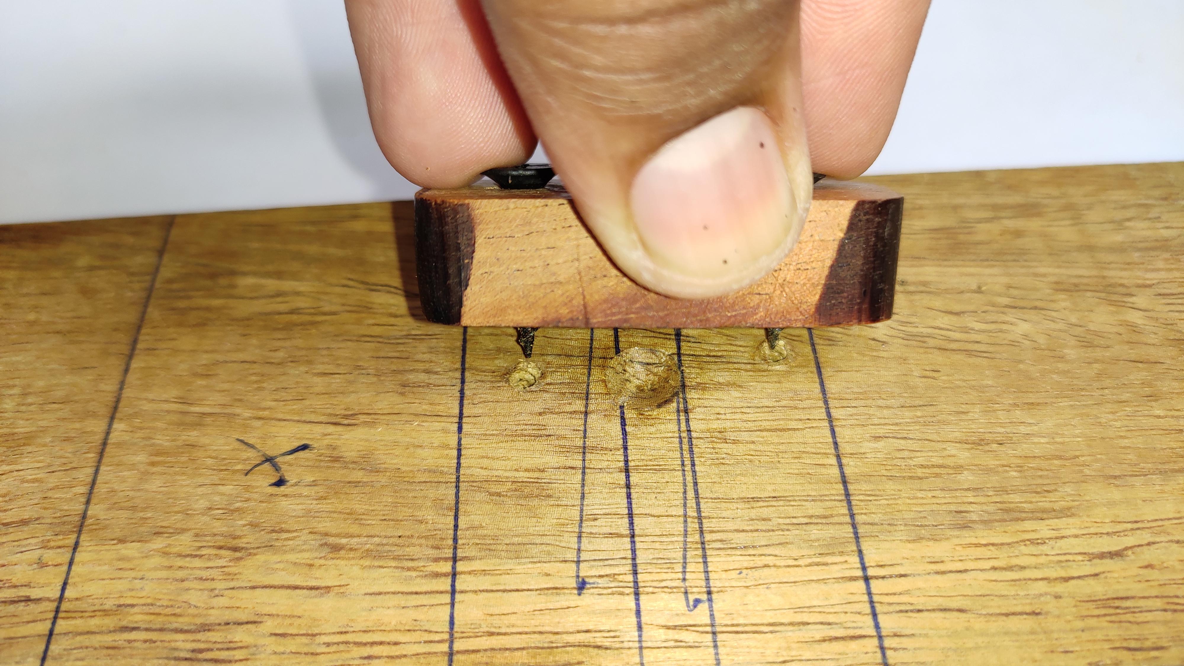
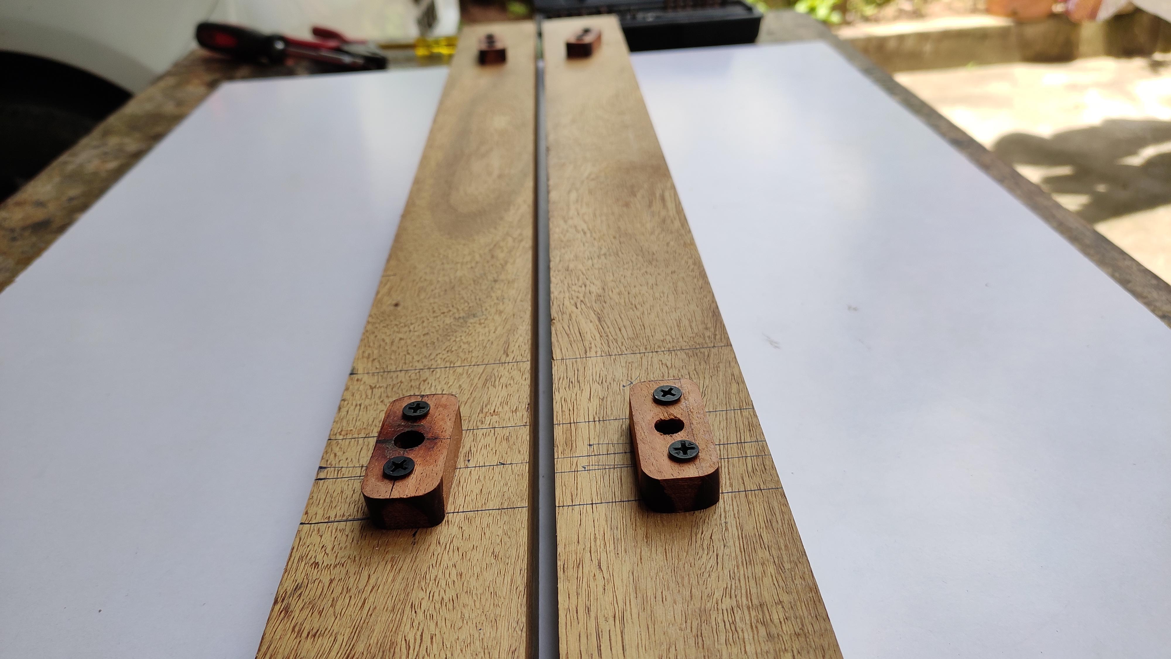
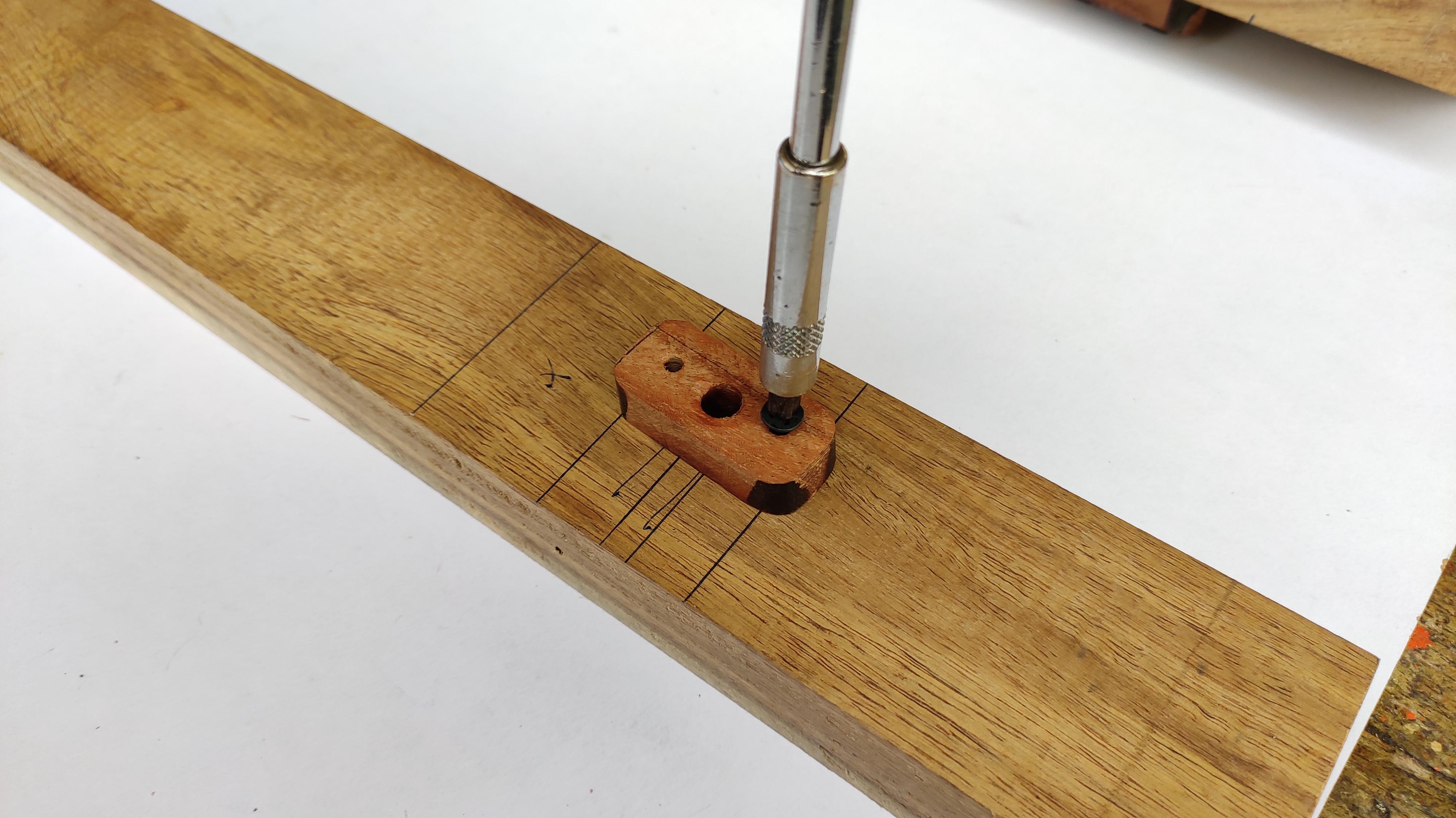
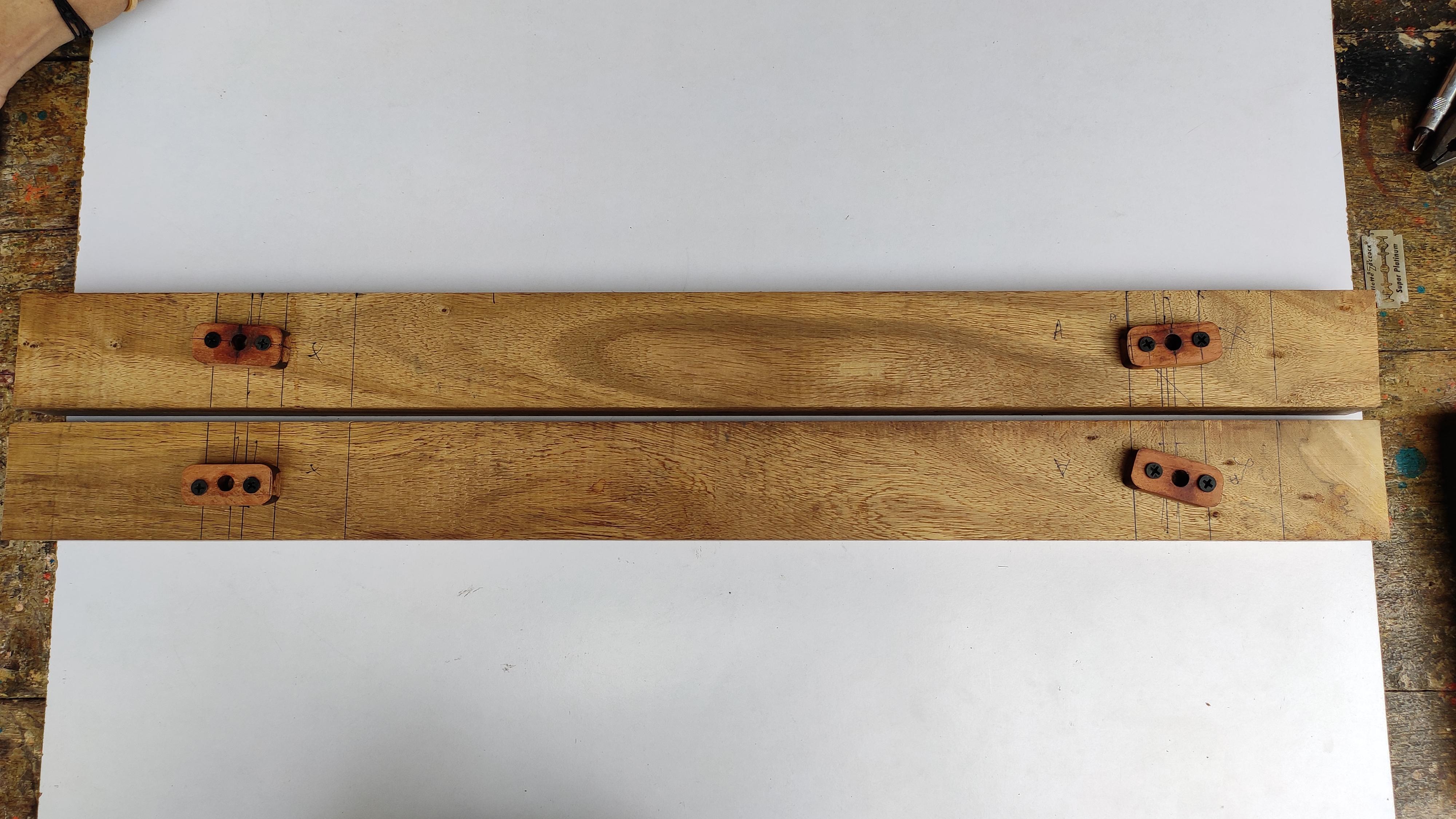
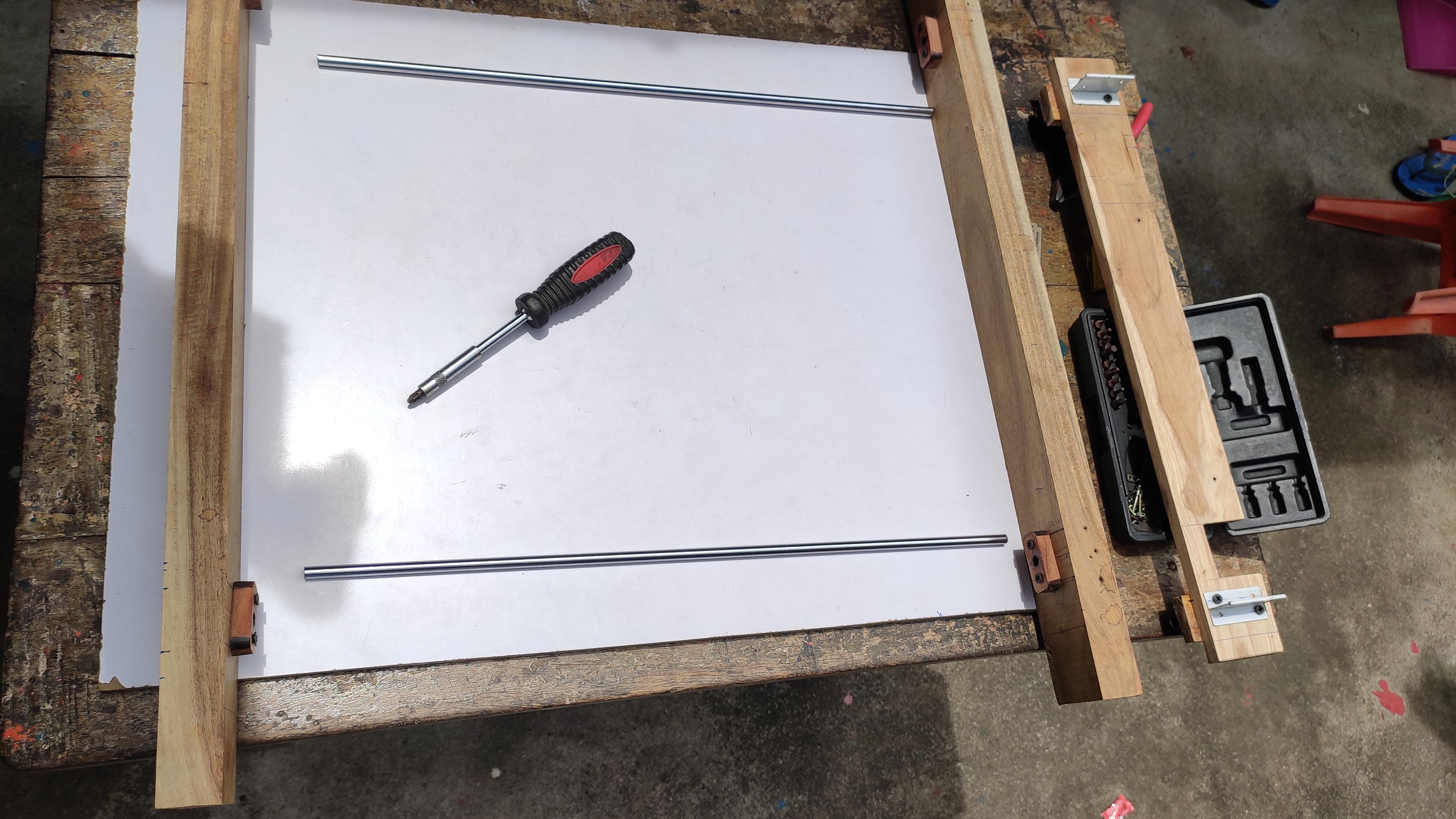
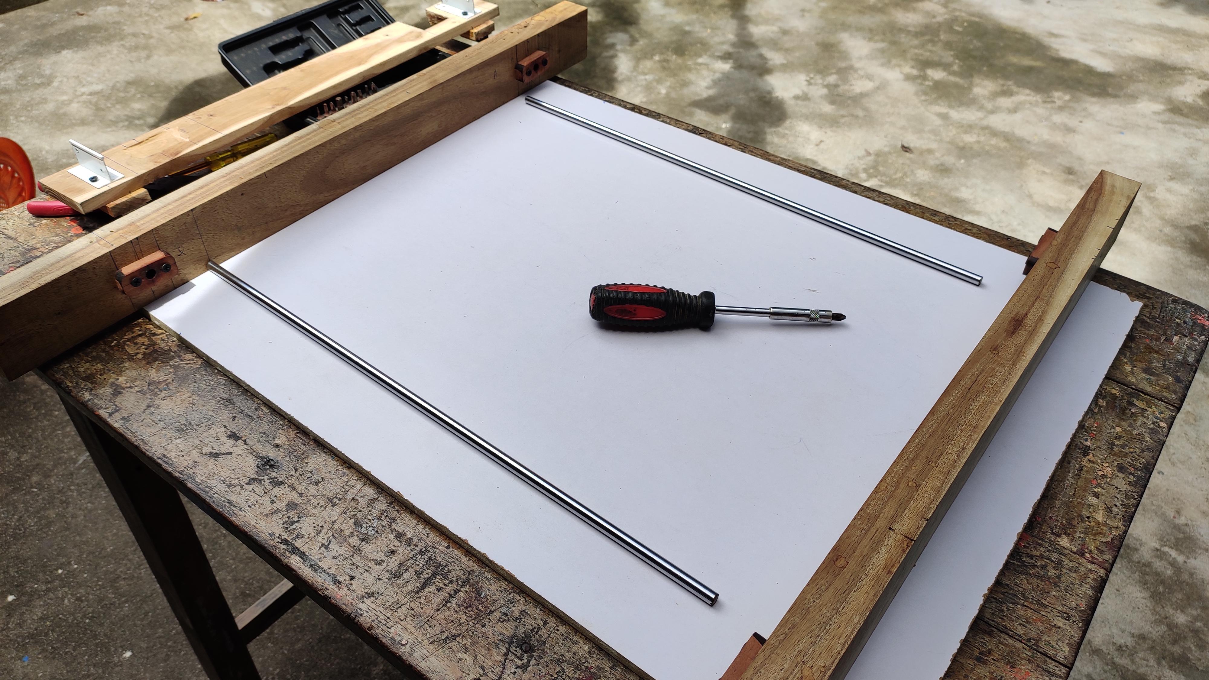
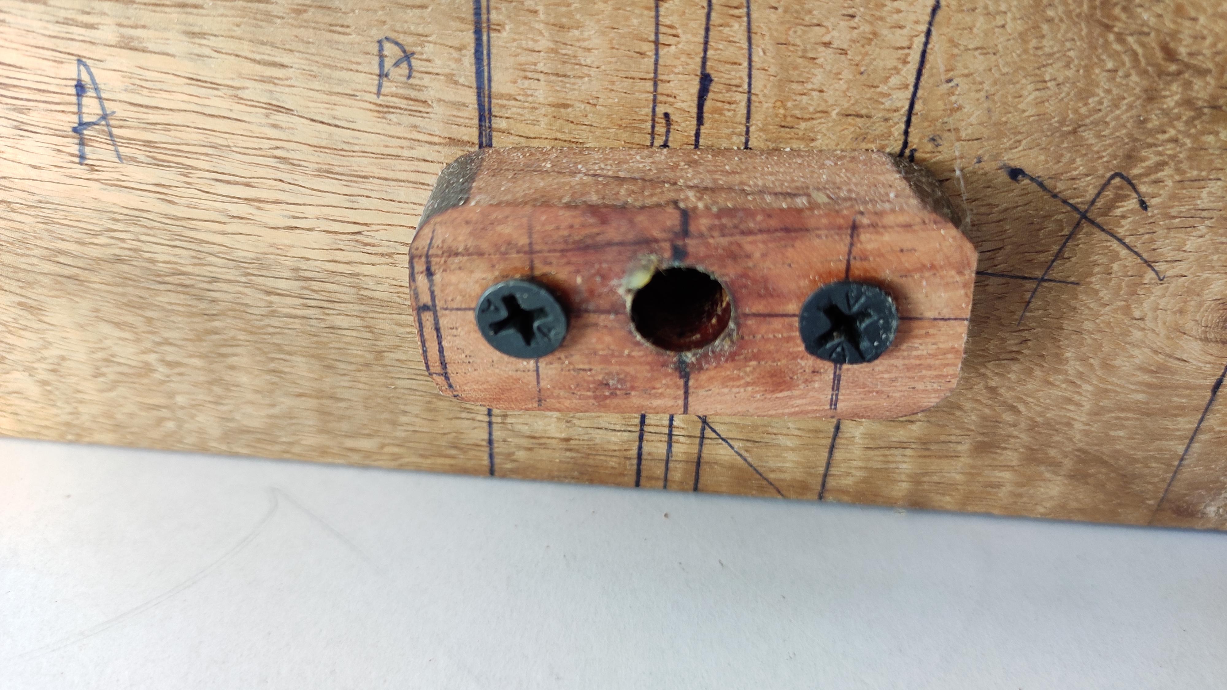
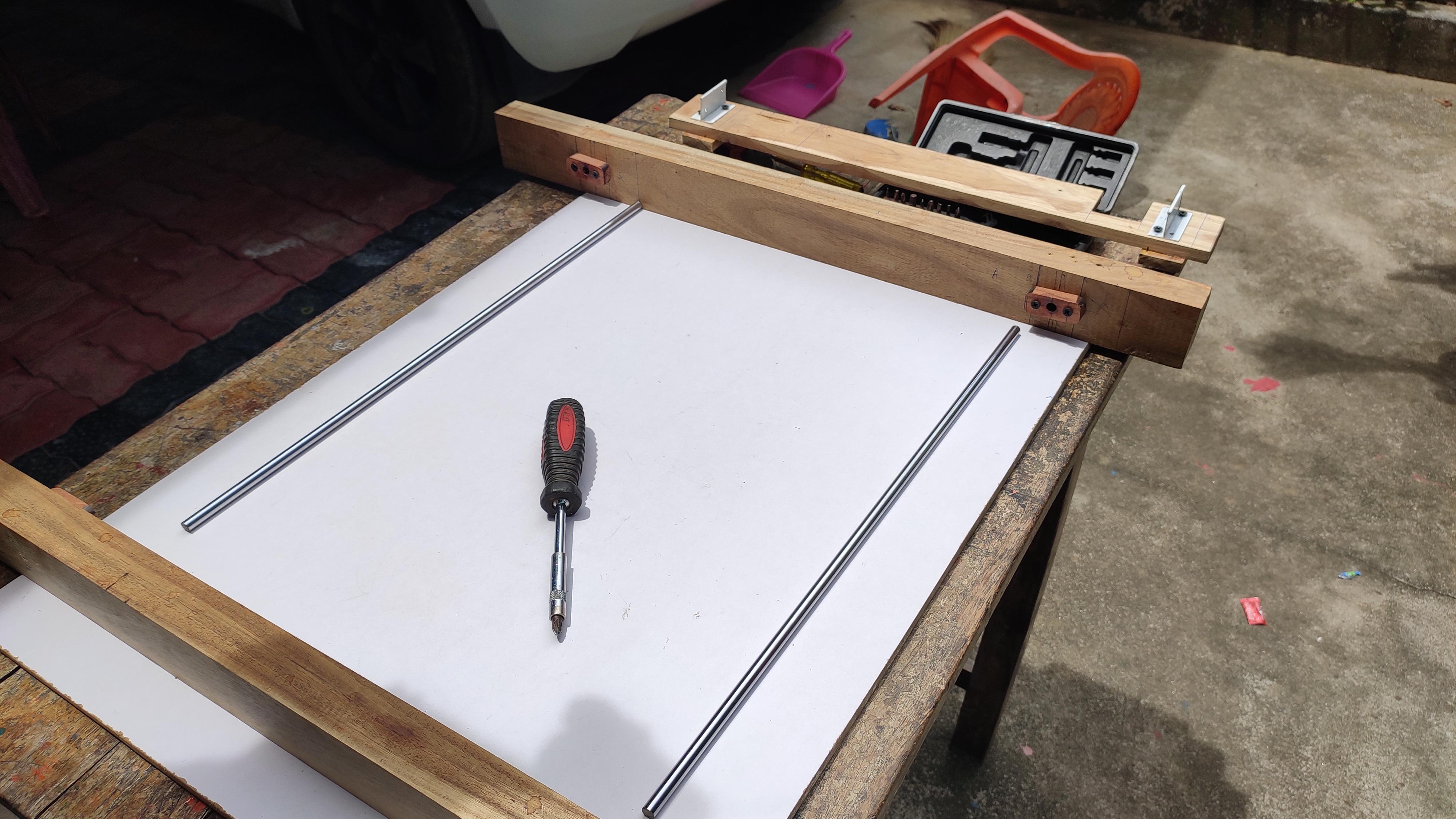
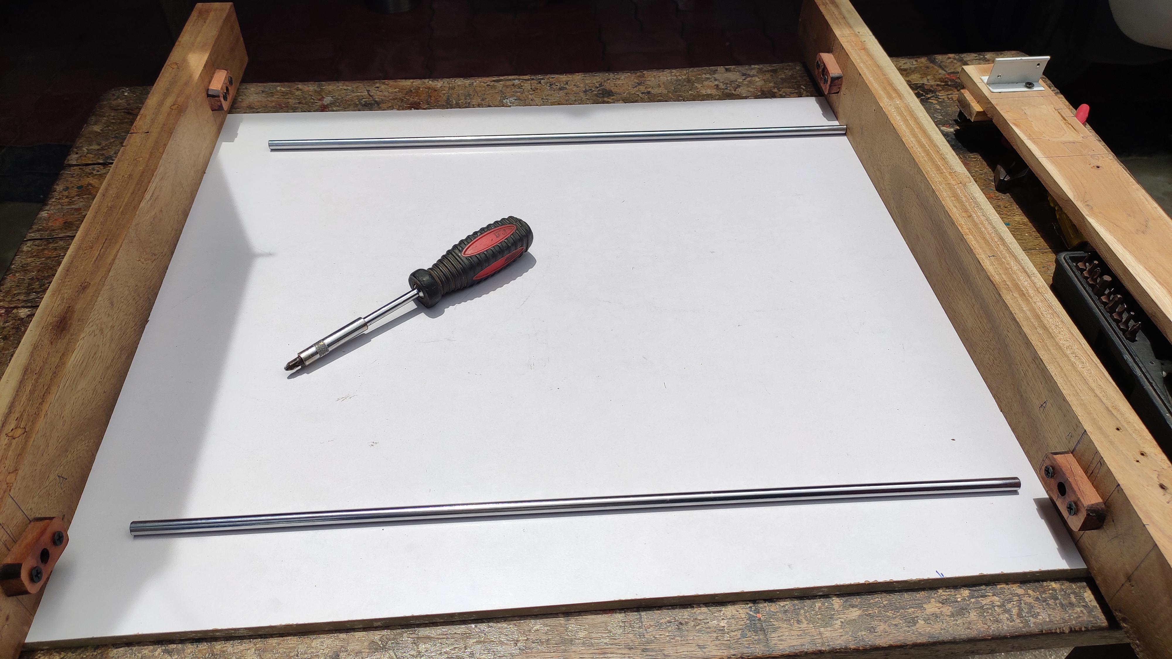
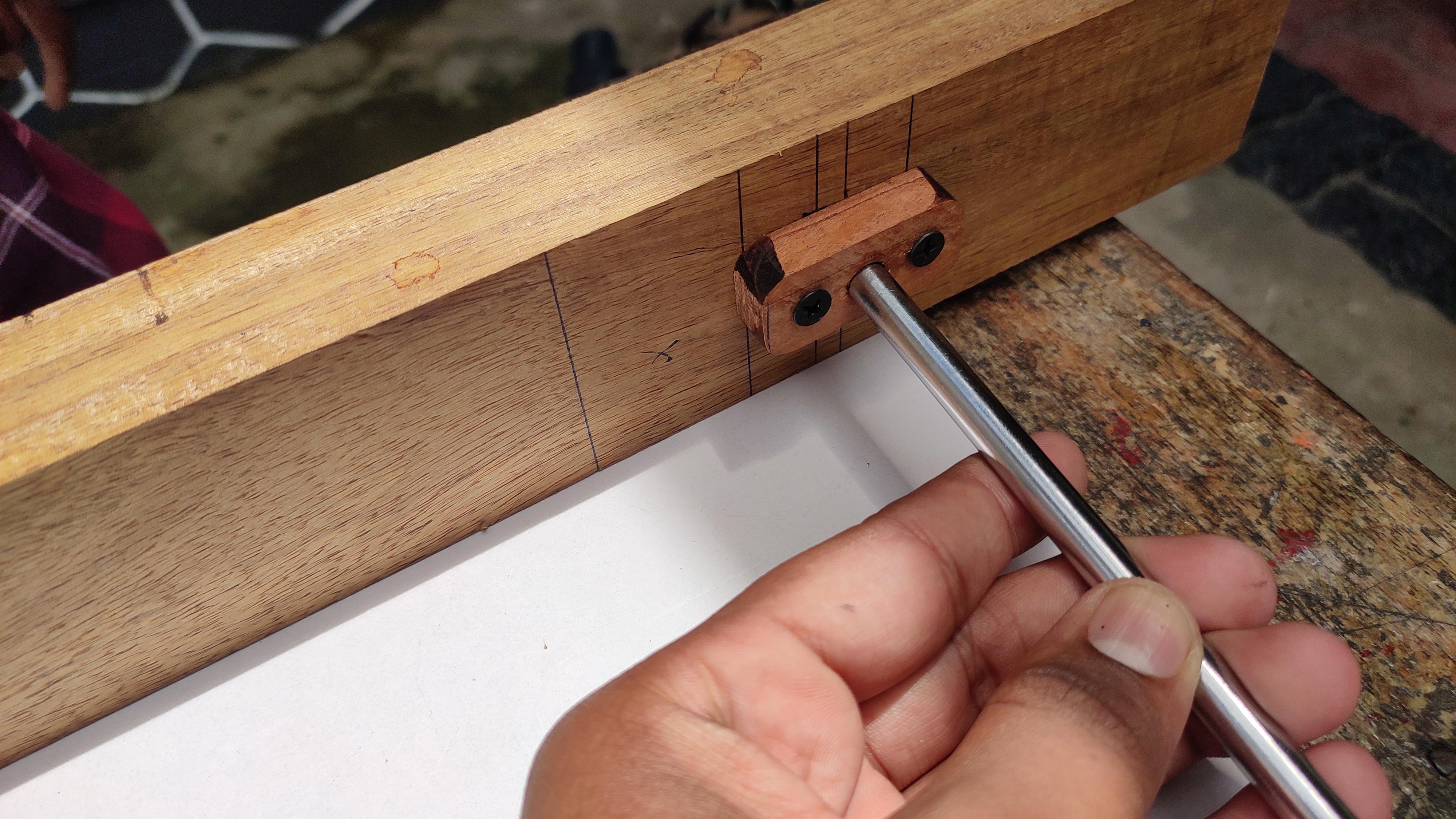
In this step i am going to attach the main two wooden frame of this project. First attach the smooth rod holder to wooden frame as shown in the image. like the first image the setup should be done. Please note that the rod holder should be fixed in equal distance and proportion in both of the block. If done with finding the correct position for the holder next tight it with thread screw, make sure that doesn't wobble.Insert the 0.5m smooth rod to the hole and double check whether the rod lies in straight between that two wooden frame. And remove it .
if you feel ok, then move on to the next step...
Fitting Smooth Rod to the X Axis Platform:
.jpg)
.jpg)
.jpg)
.jpg)
.jpg)
.jpg)
.jpg)
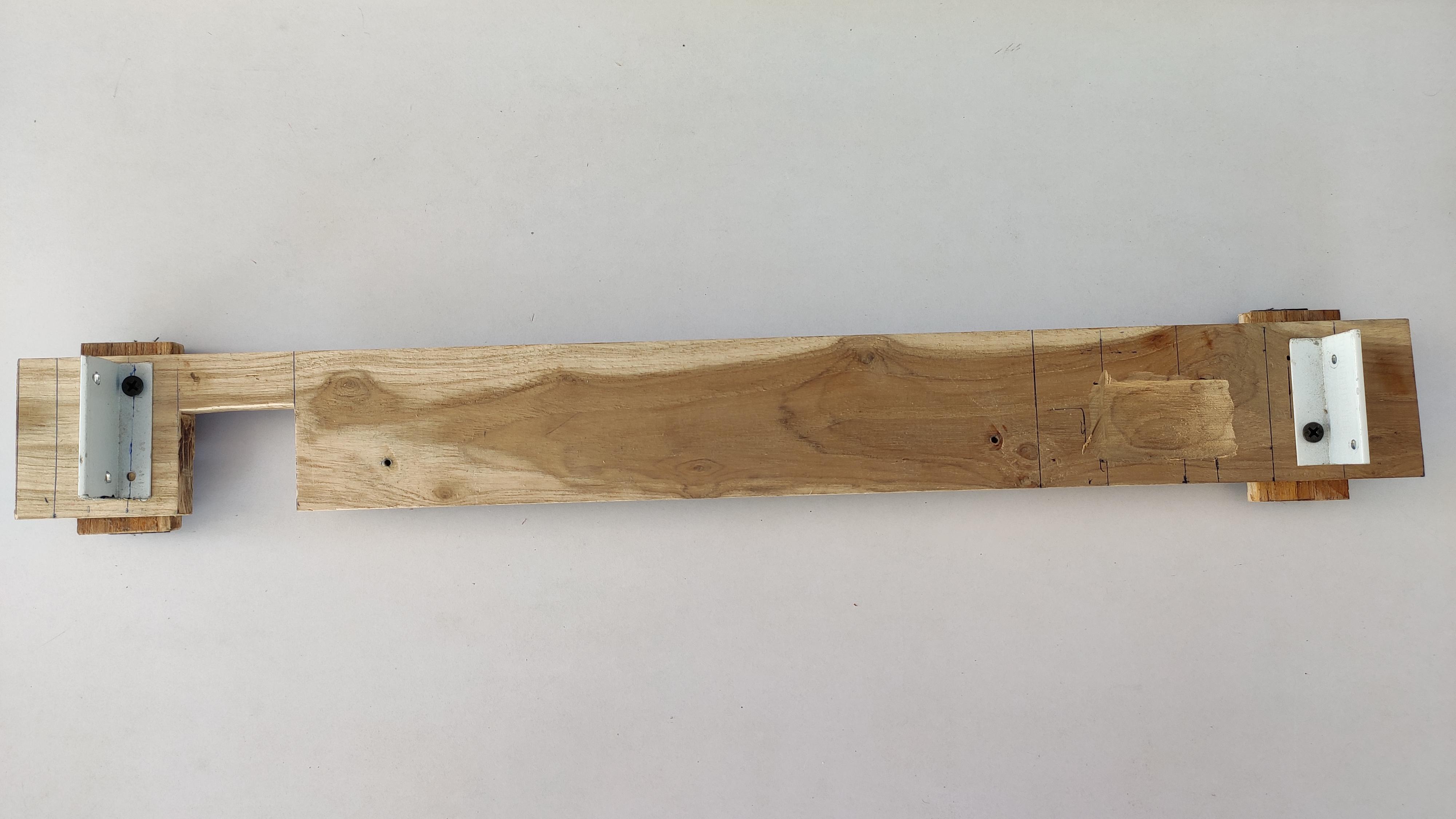
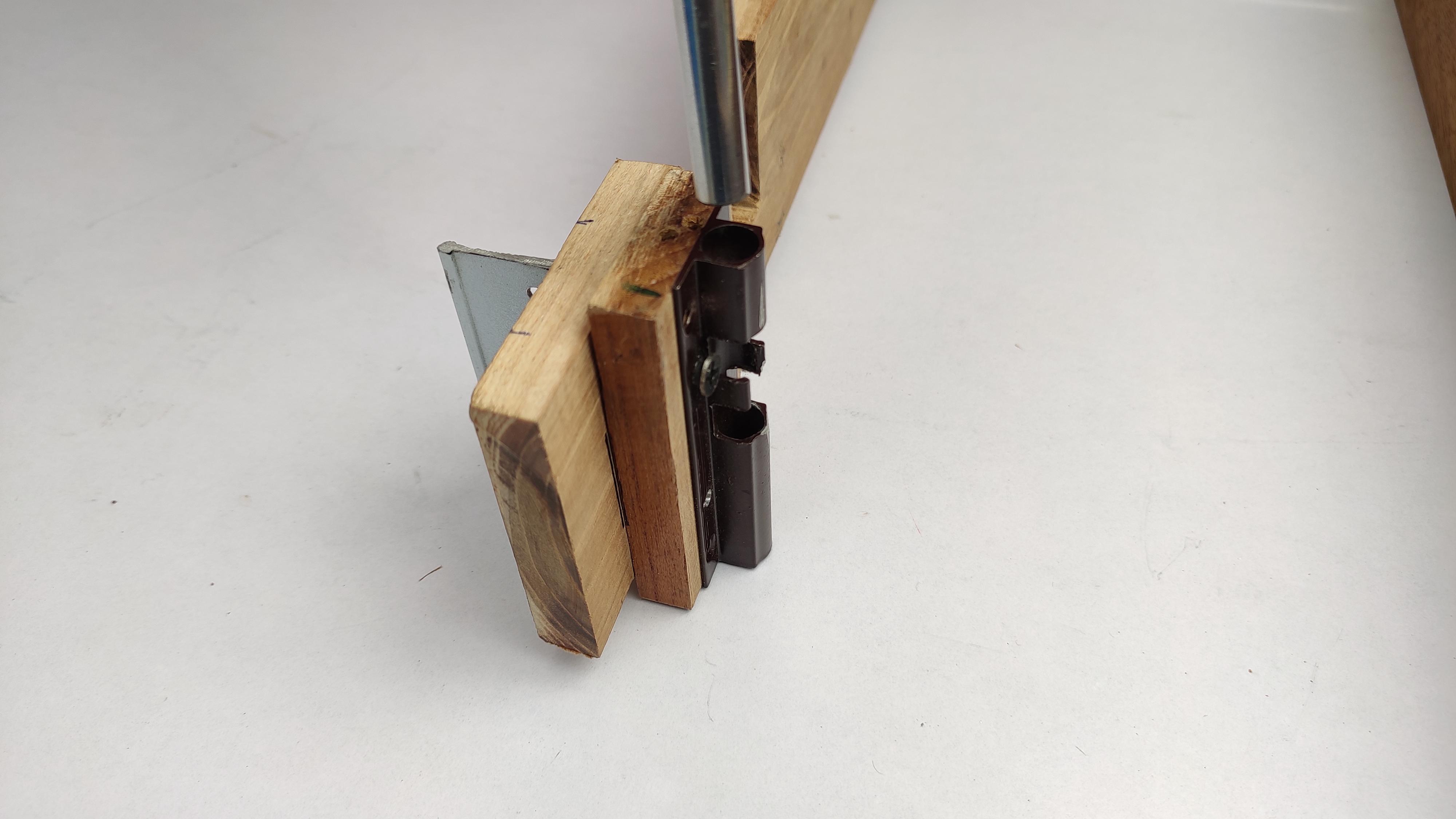
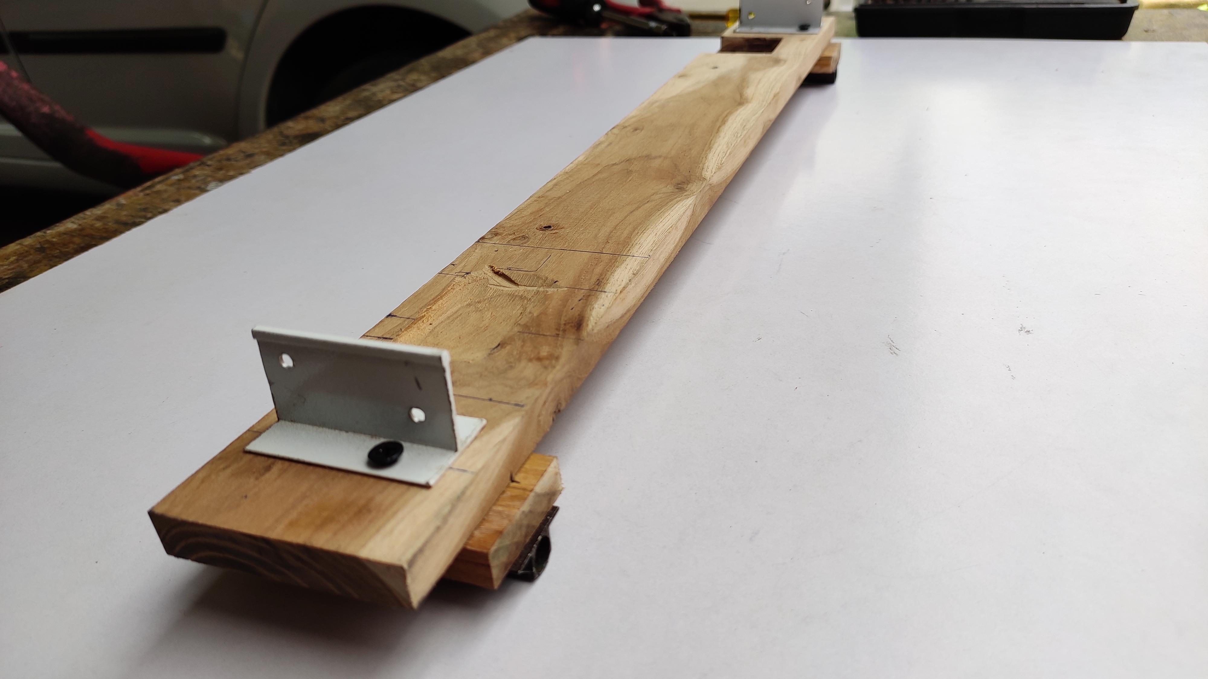
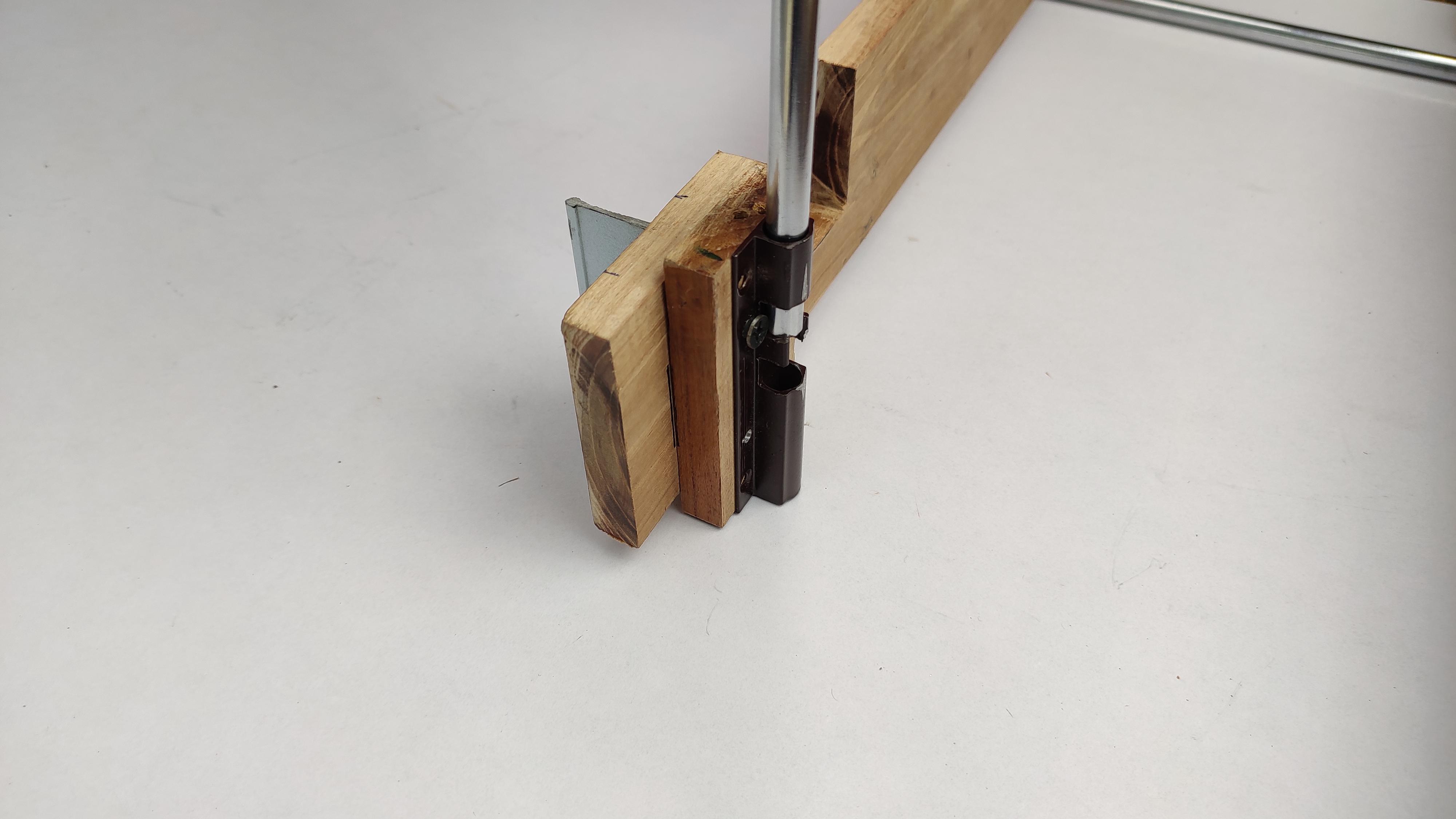
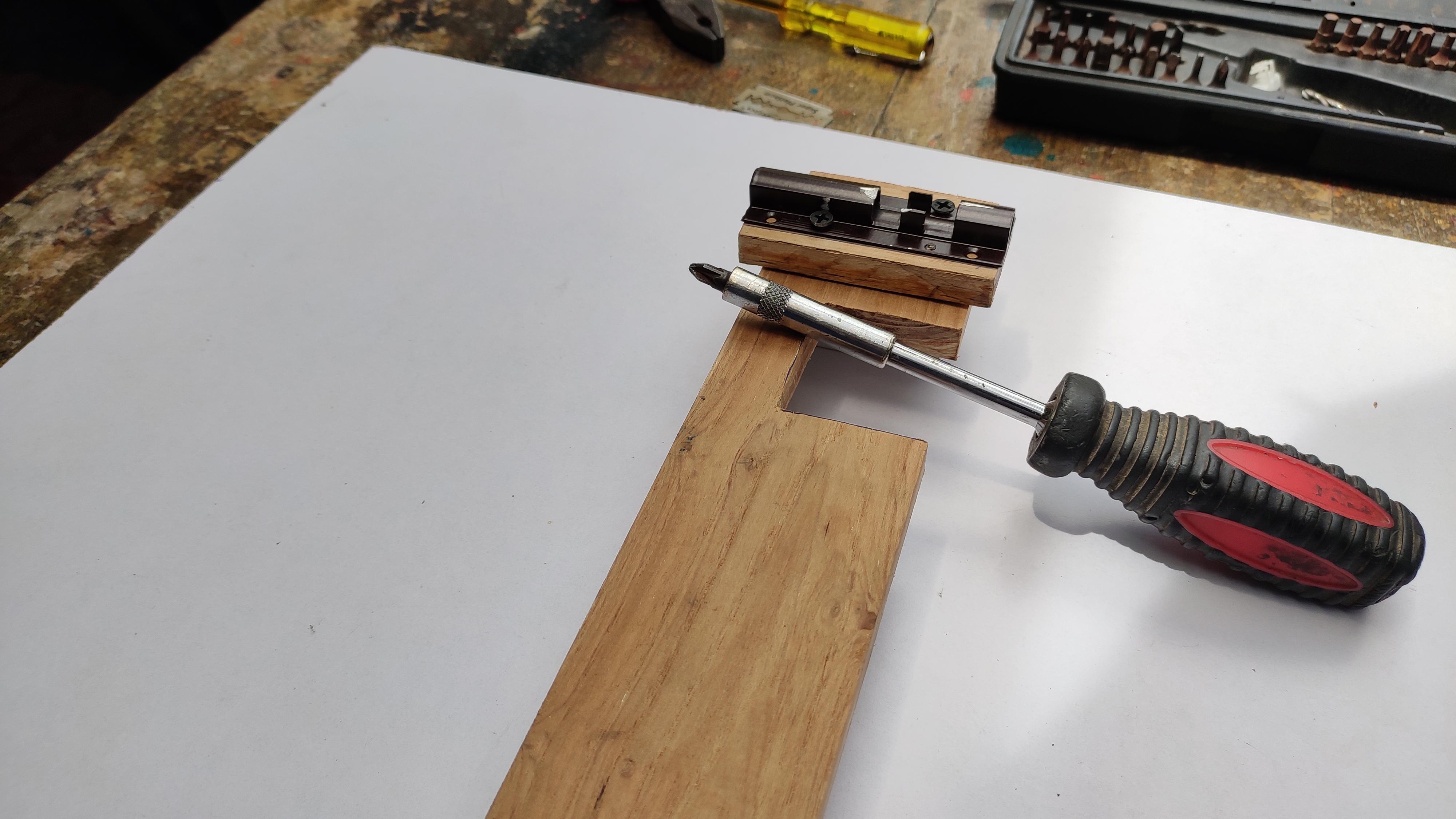
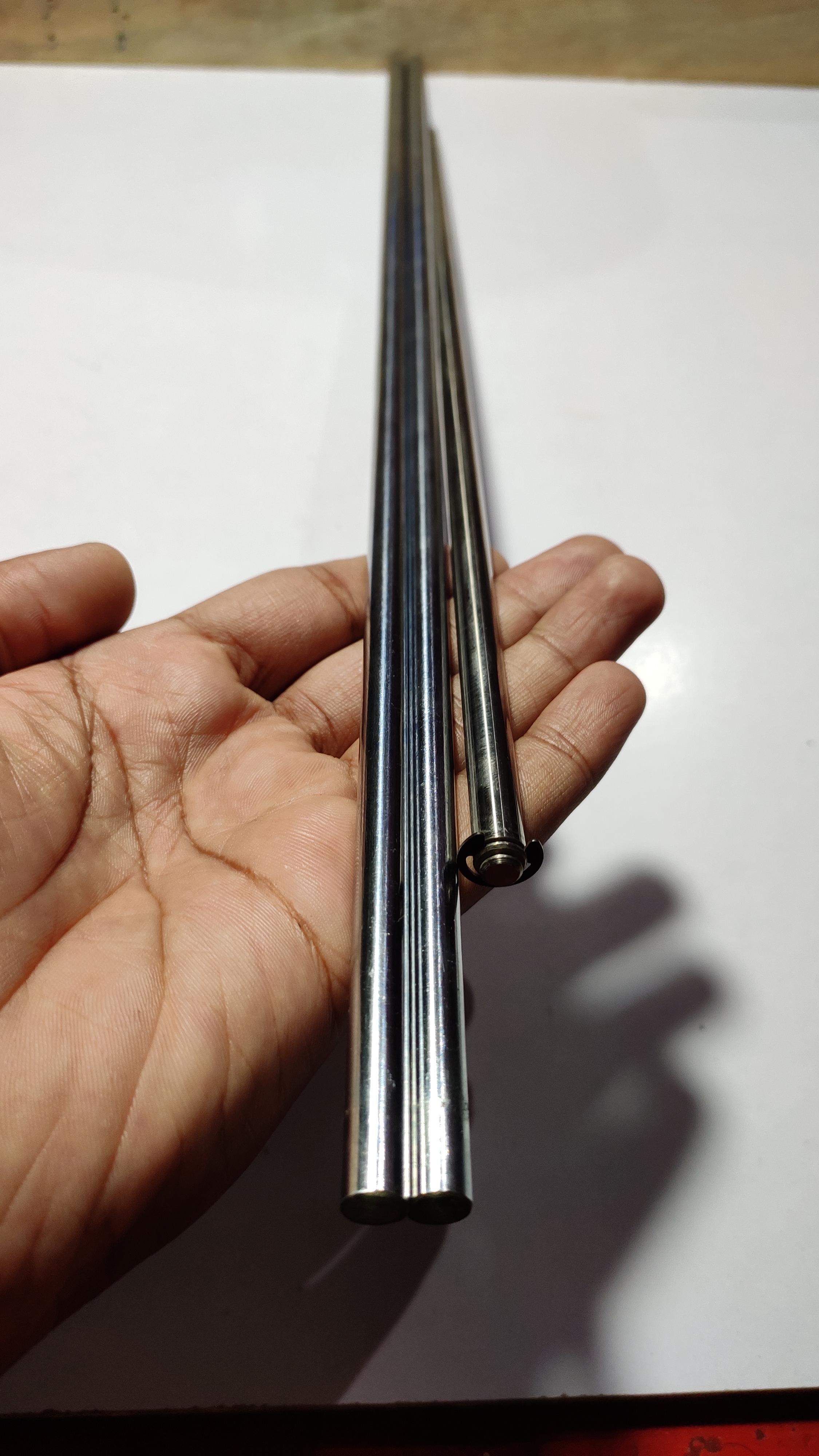
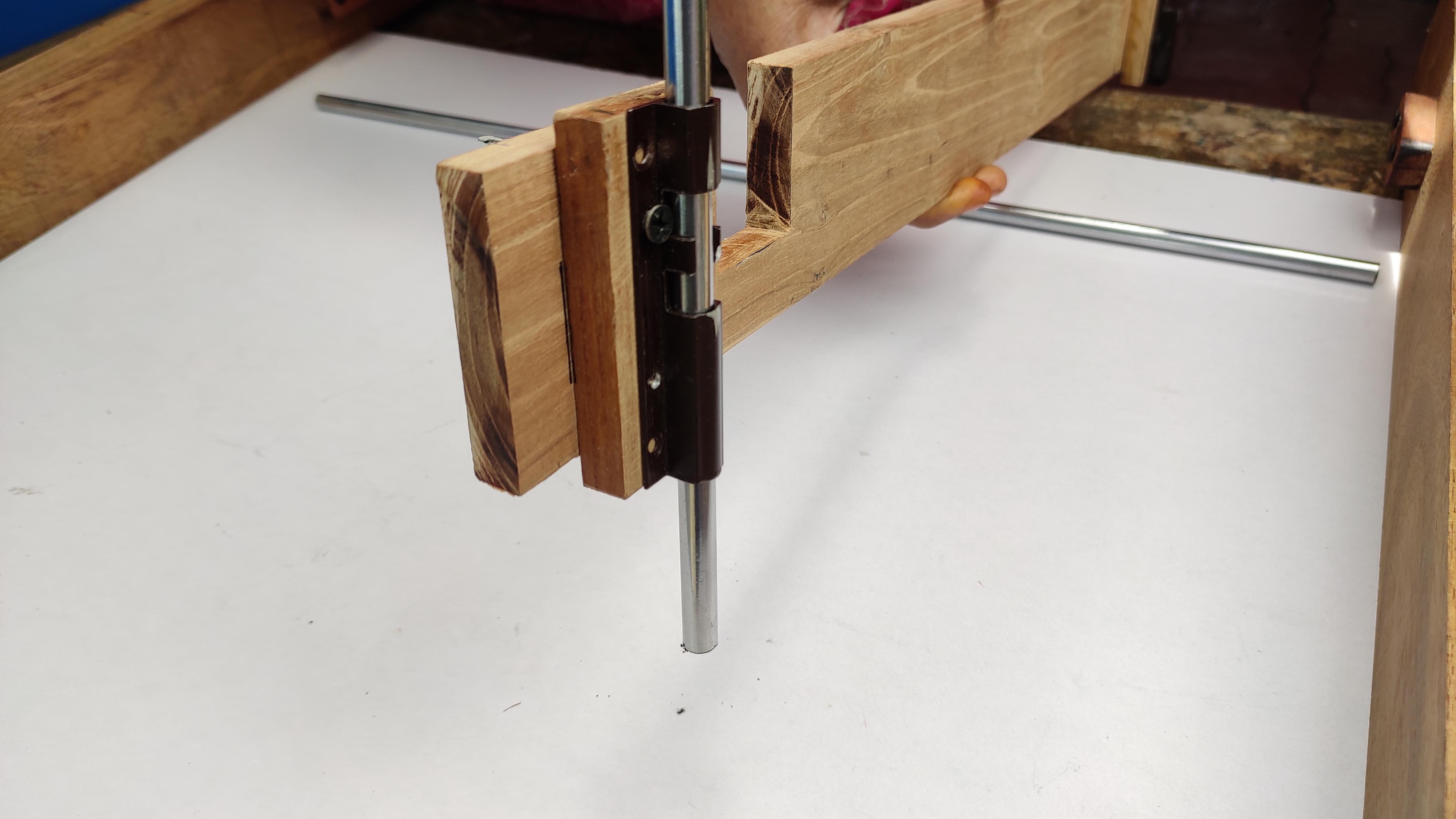
Make a platform for the x axis, so we have to make 60 x 6.5 cm dimension wooden block. cut the area to fit for the stepper motor. Here i have used two door bolts as linear bearing slide. Take it and attach it behind the x axis linear rail platform, ensure that this too doesn't shake in between. Next insert the smooth rod into the linear bearing and fix it to the rod holder on the both ends. And just check the x rail platform moves smoothly up and down through the rod.
If not, do not get confuse, your alignment of the holder may changed, please check and change until you feel smooth motion.
Completing Wooden Frame & Belt, Rod Holder
.jpg)
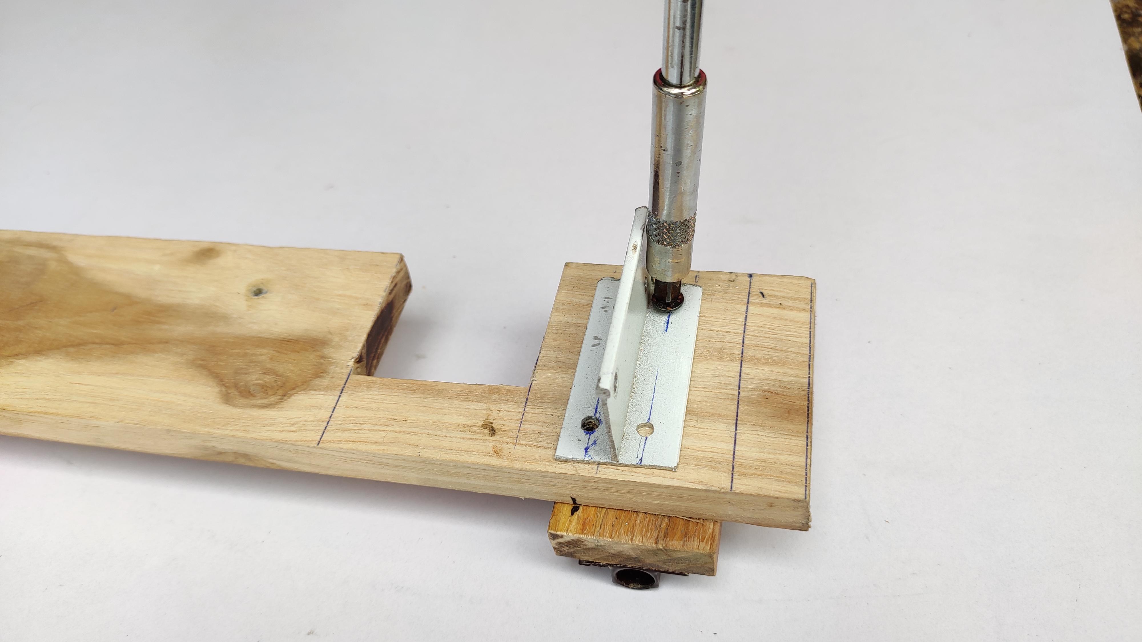
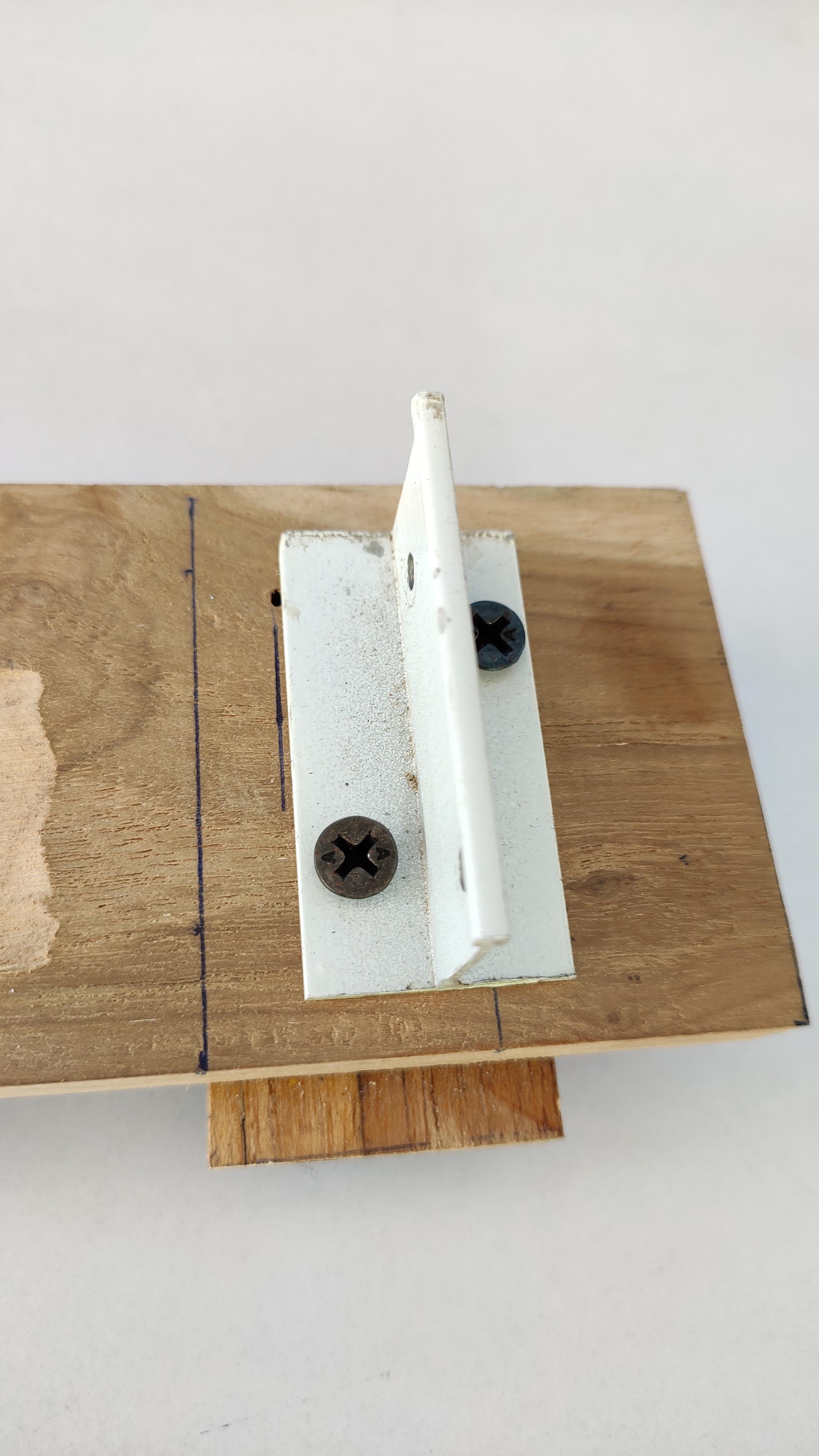
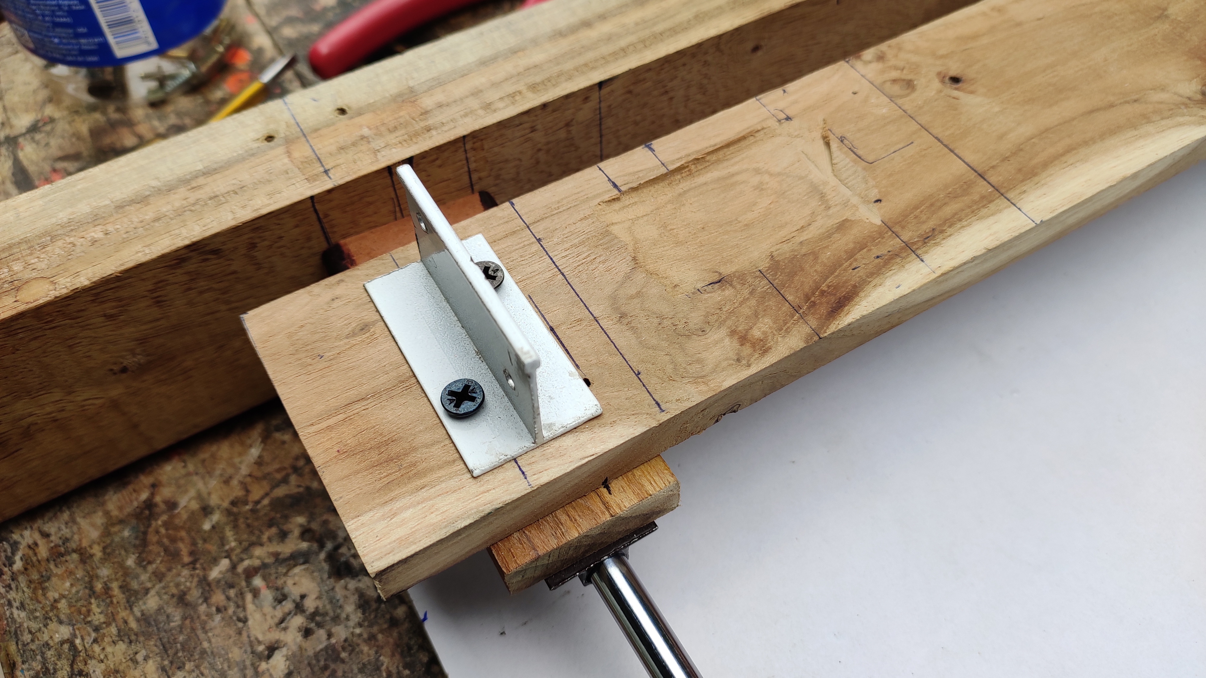
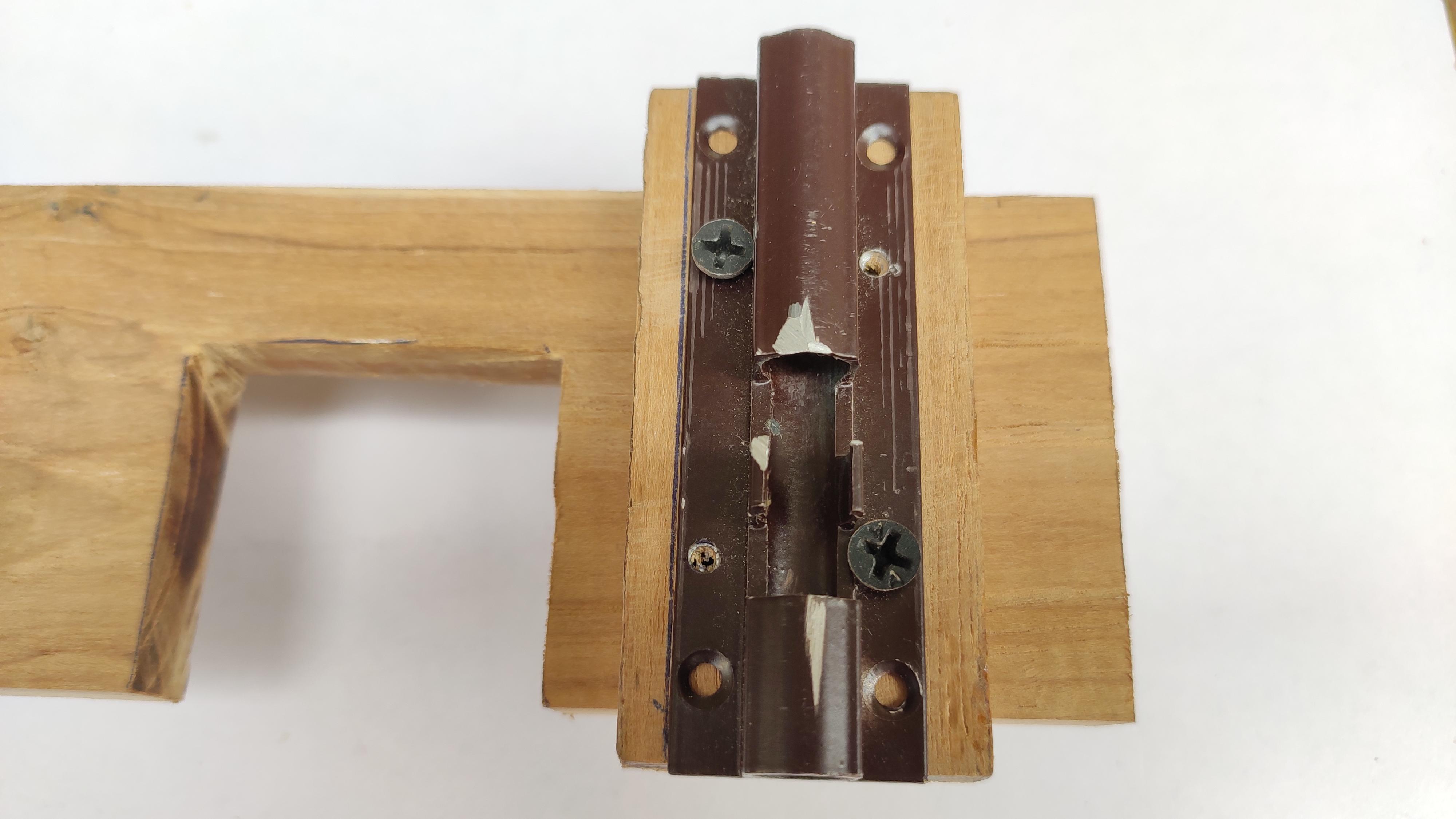
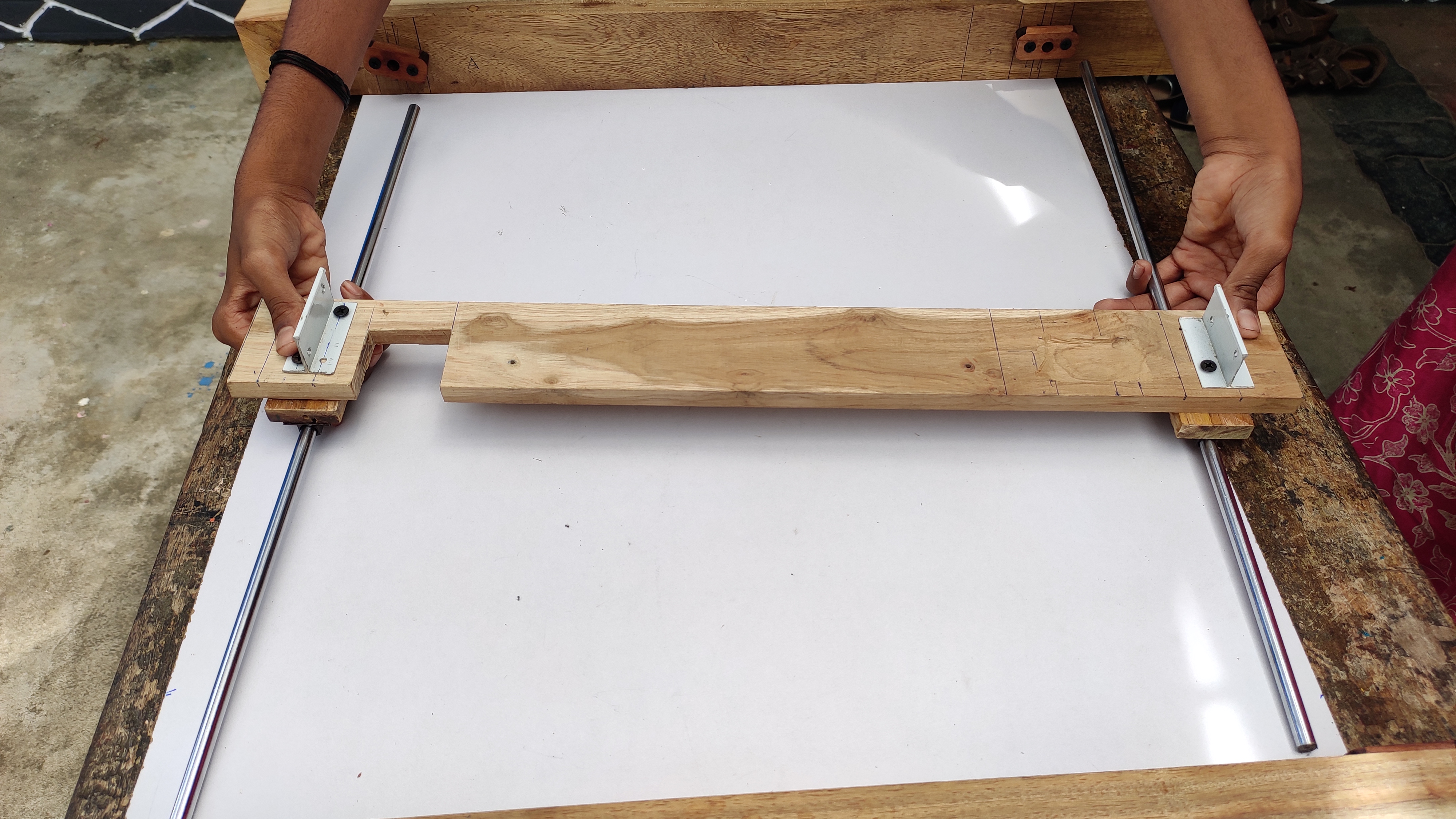
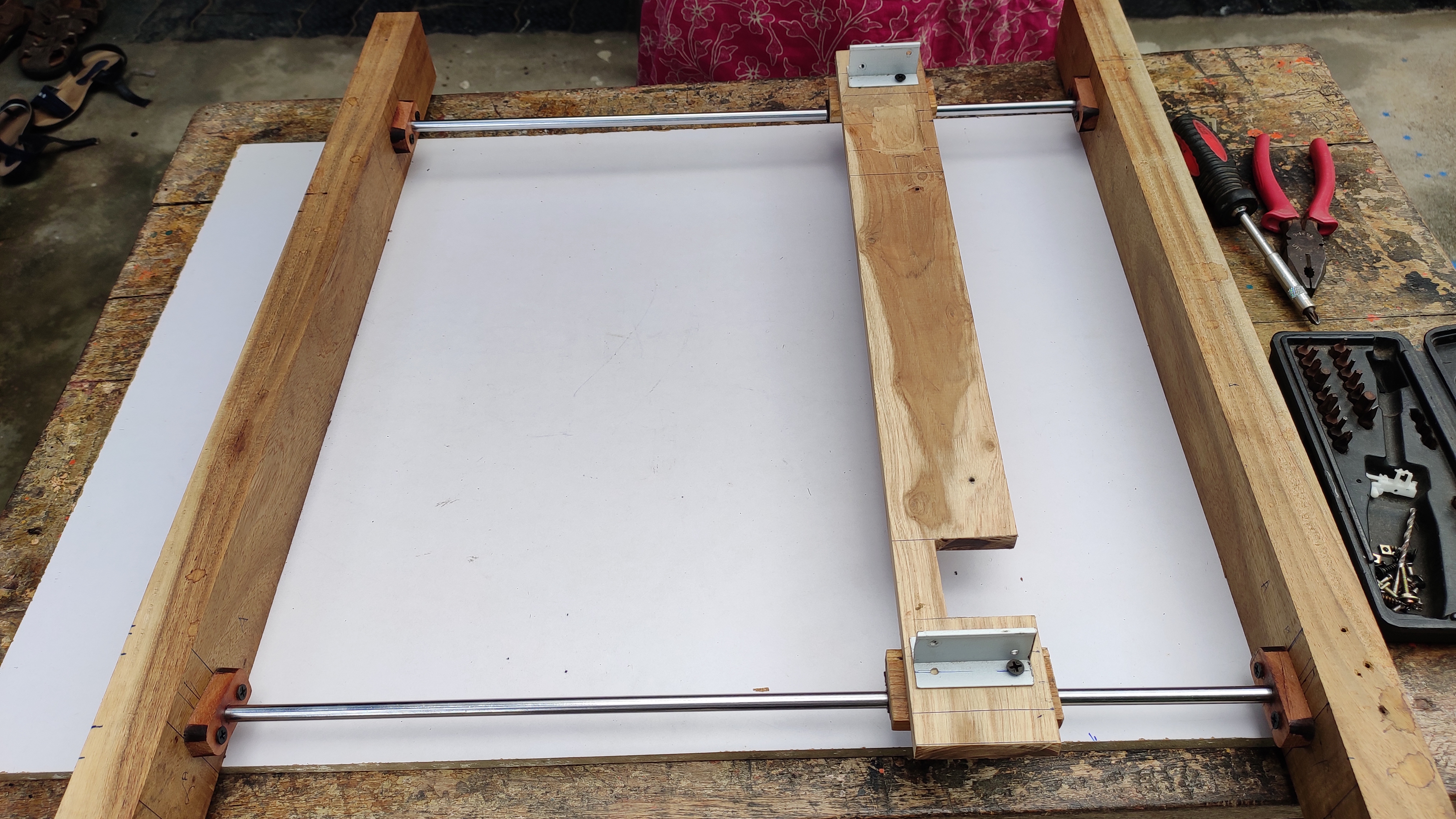
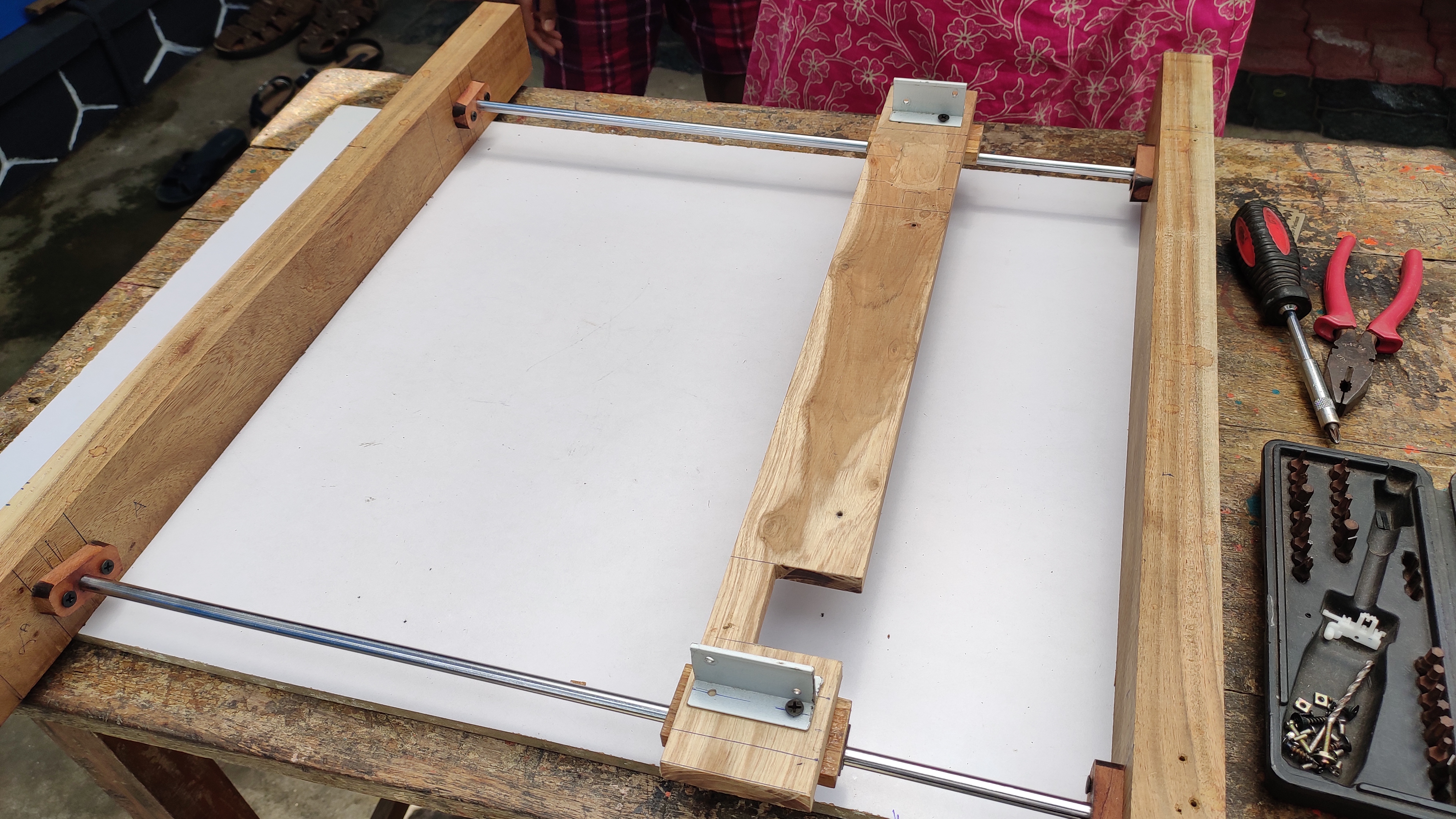
I hope you setup your machine as shown in the first image. your own ideas are welcome.
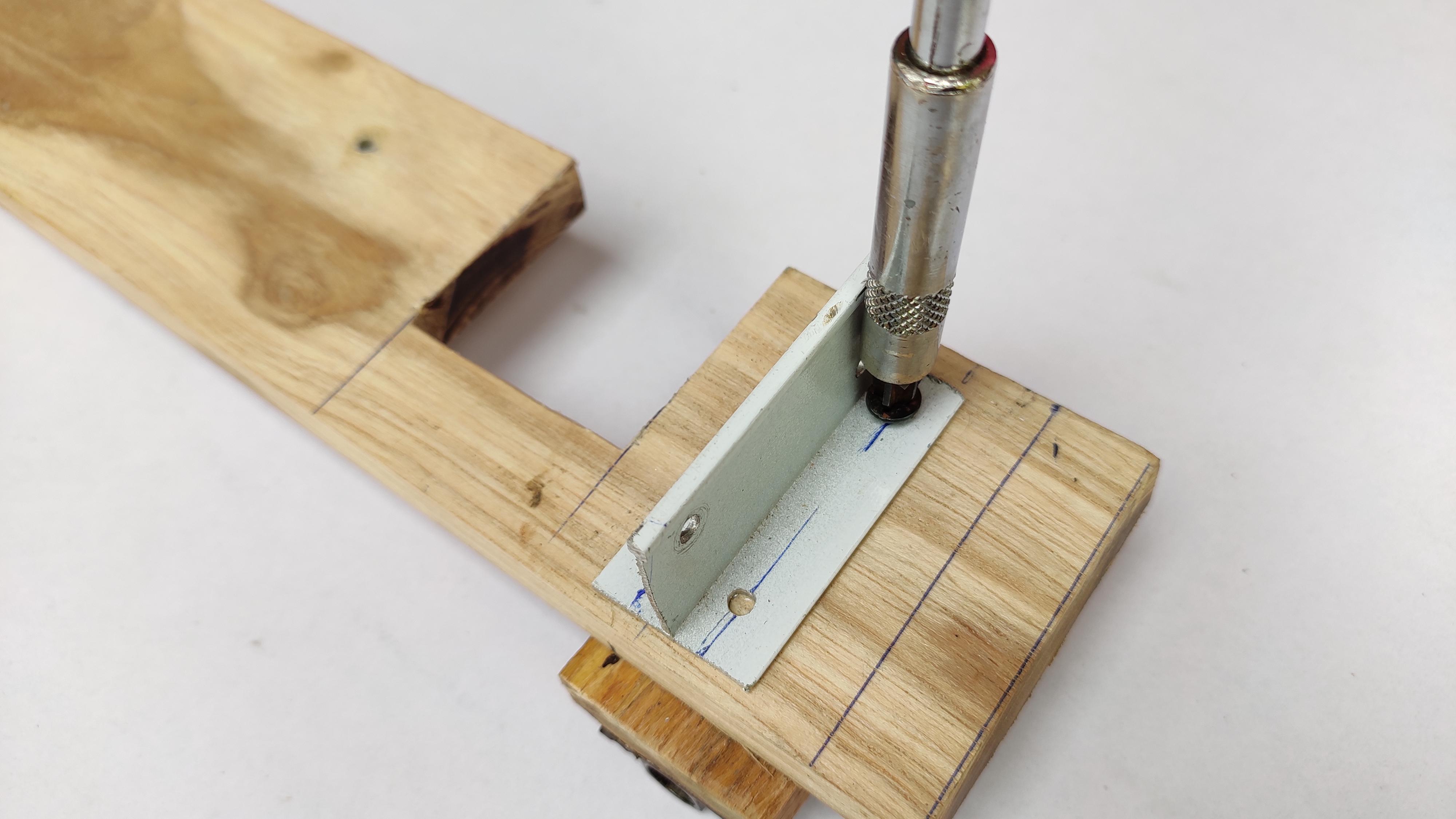
Fix the aluminium channel on both side of that platform. This is to attach the timing belt to platform. I fixed directly up side of the smooth rod. If done you have finished all most setup for the Arduino cnc plotting machine.
If needed apply some grease on the rod so the platform gets much smoother movement.
Assembling X-Axis Frame & Linear Rail
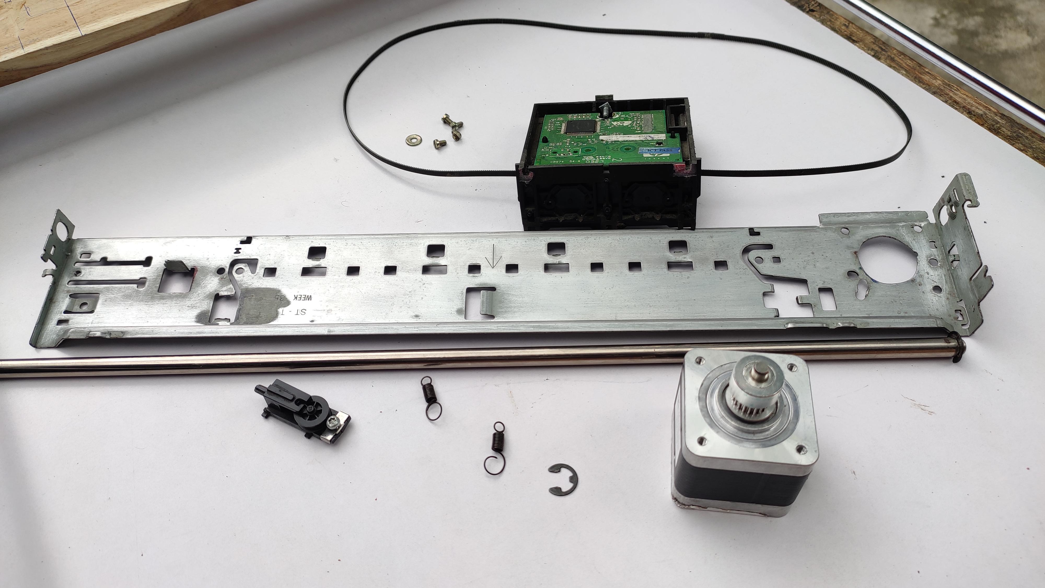
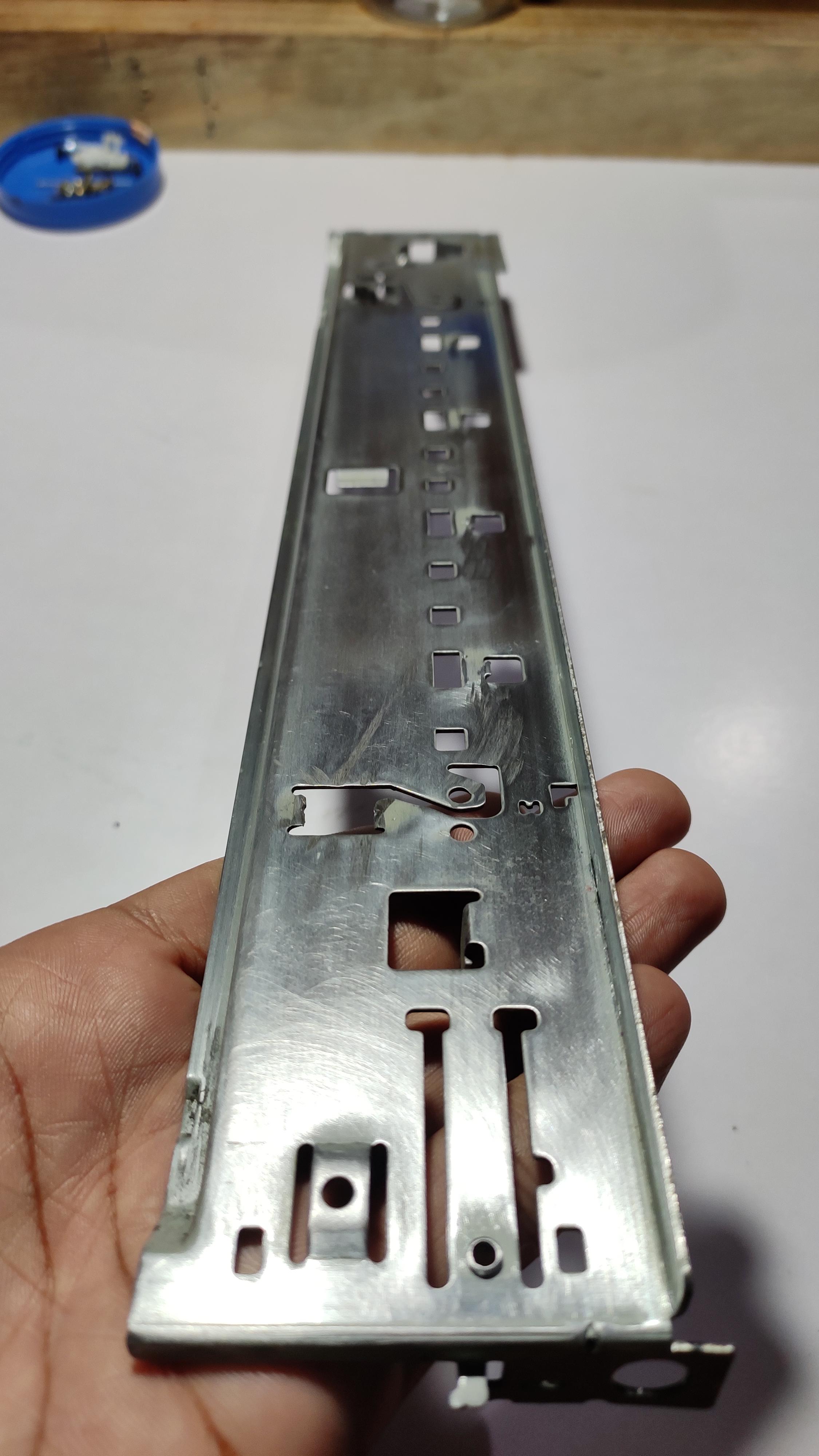
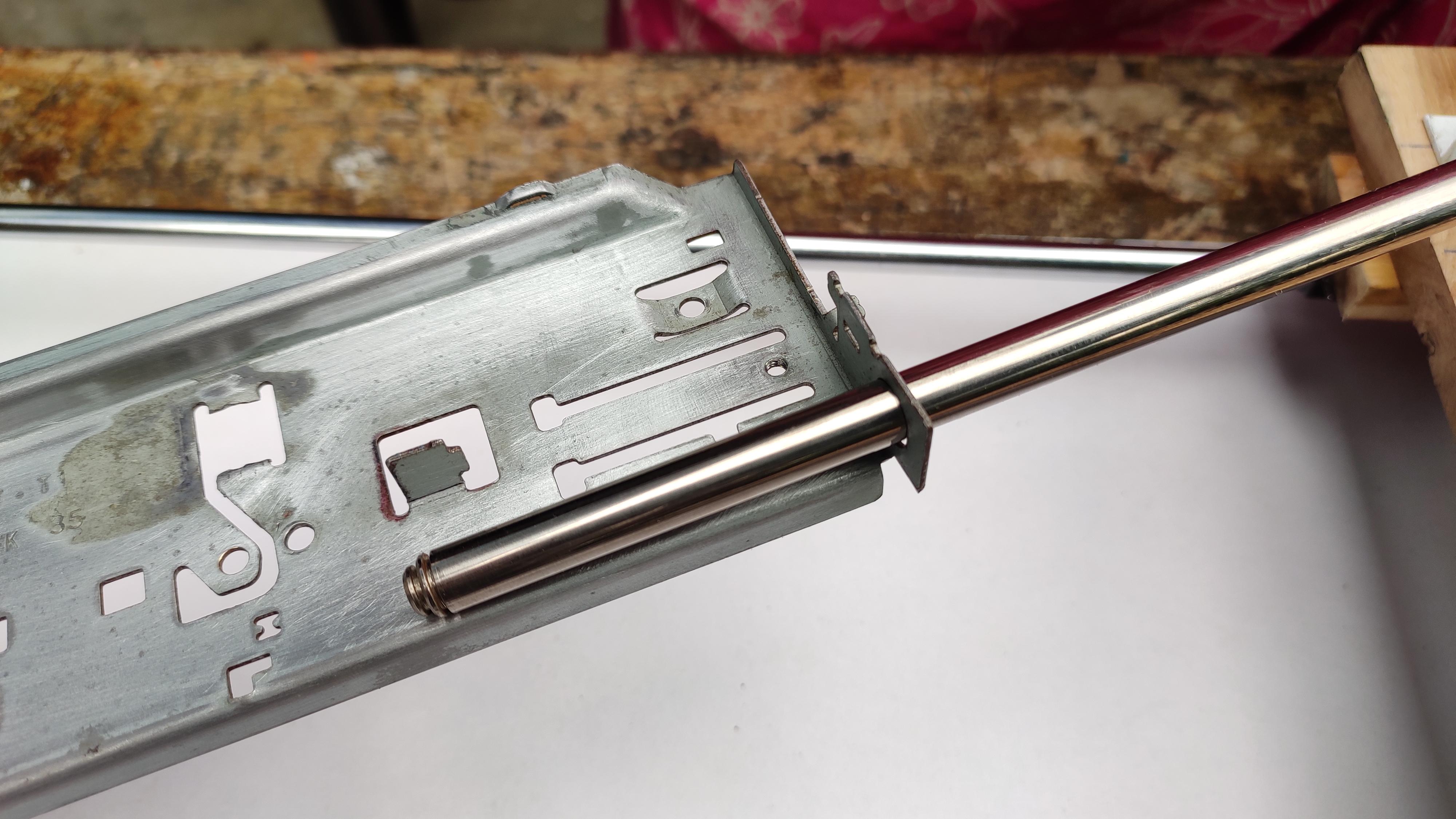
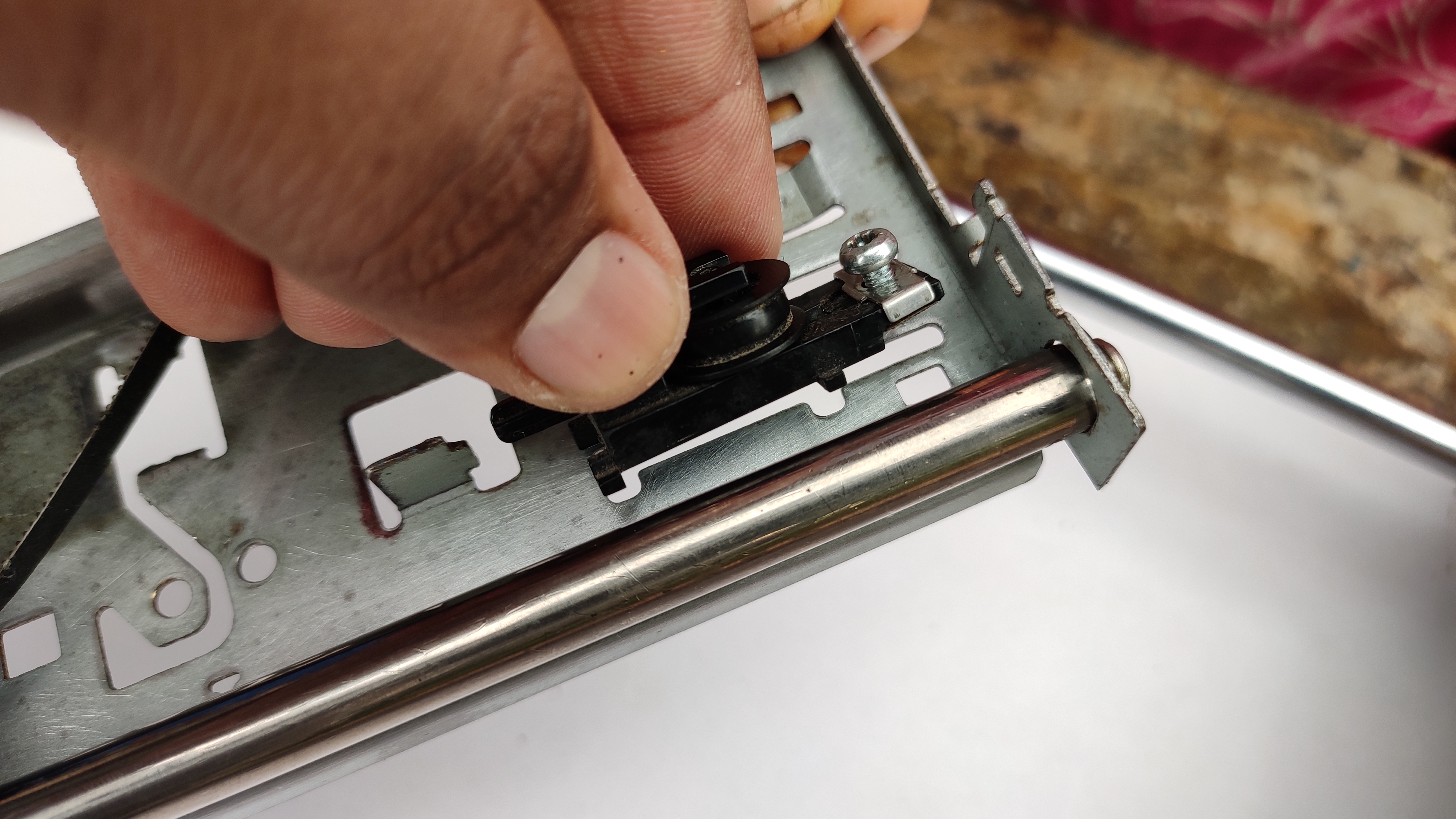
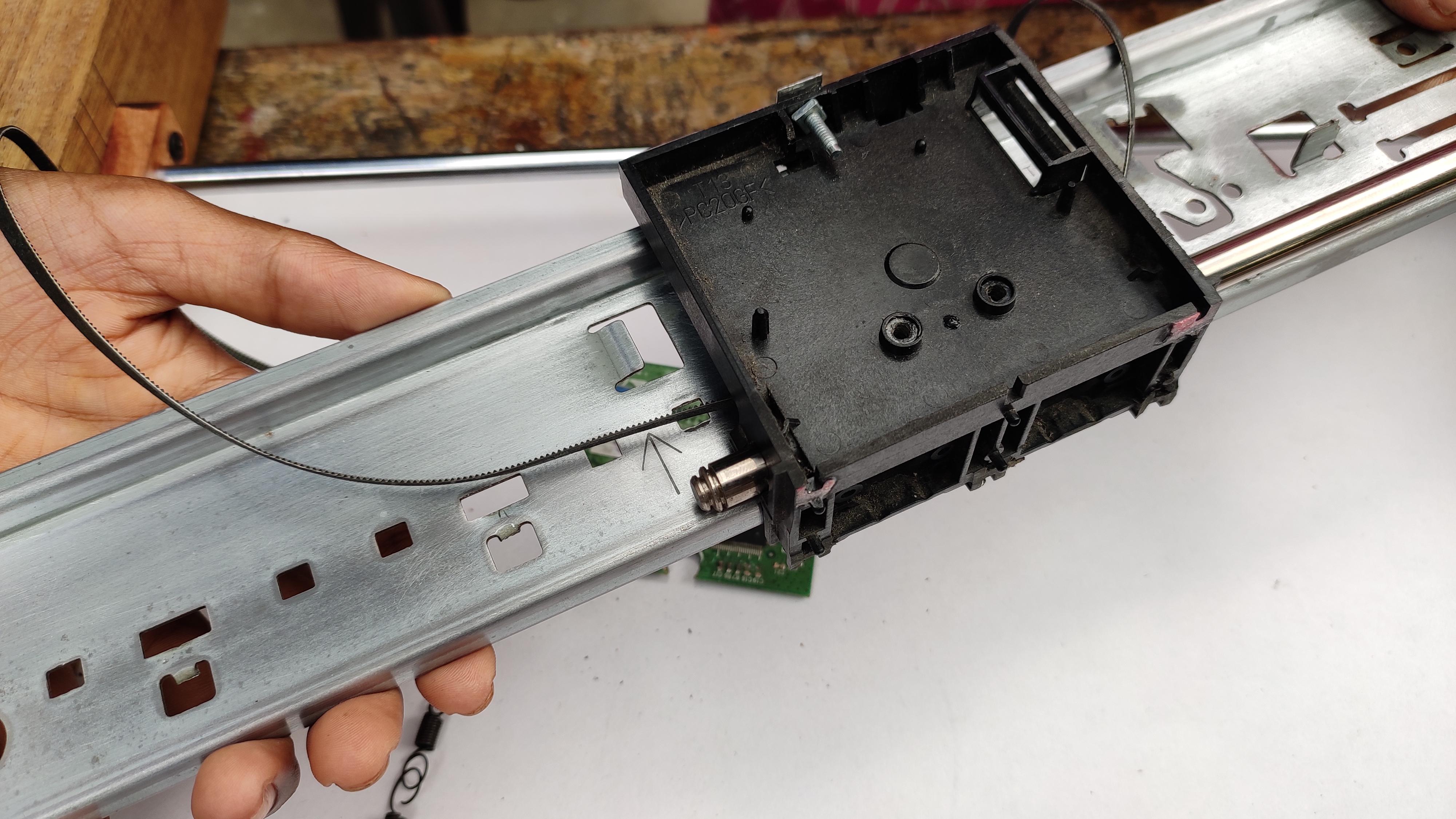
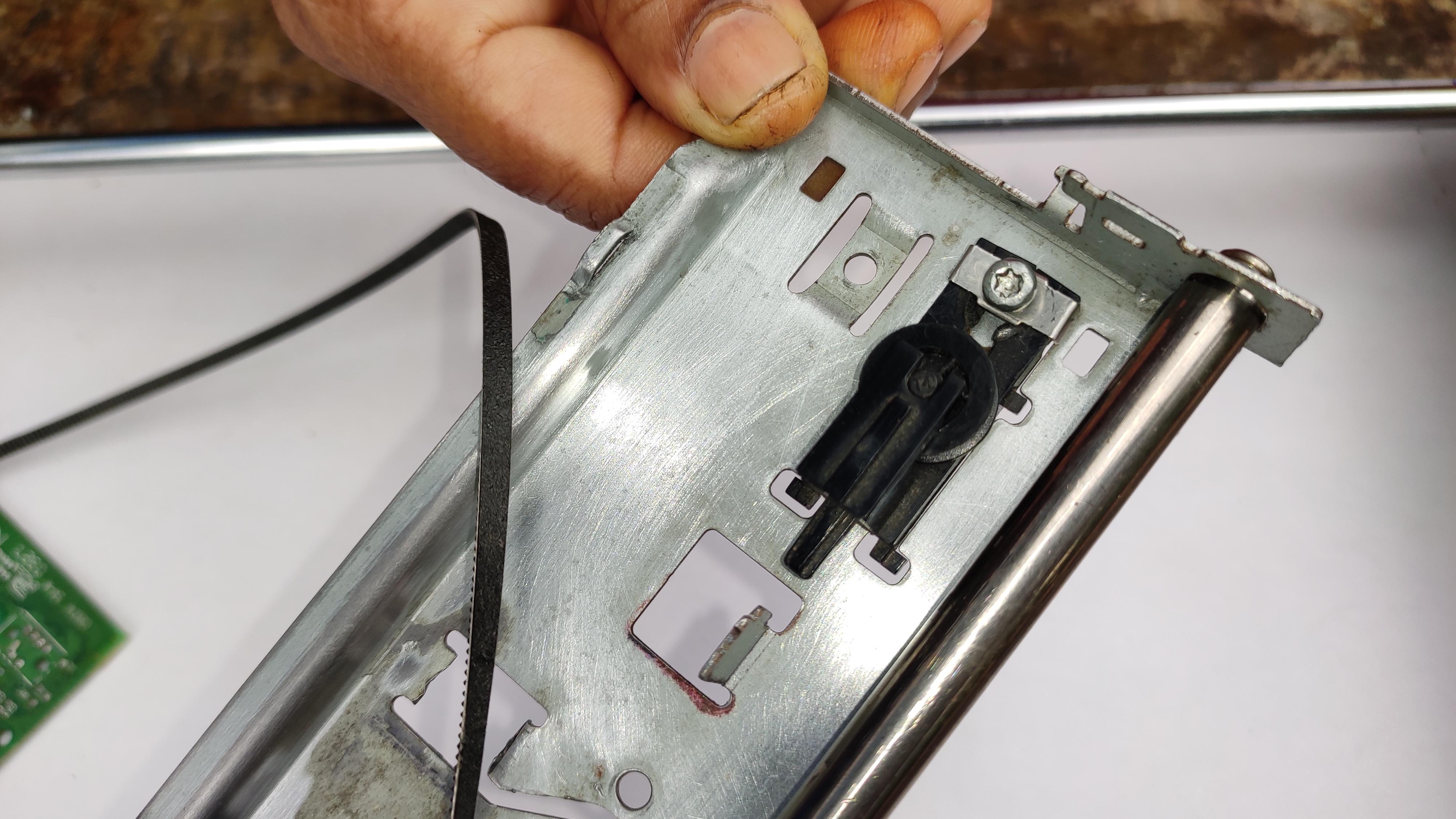
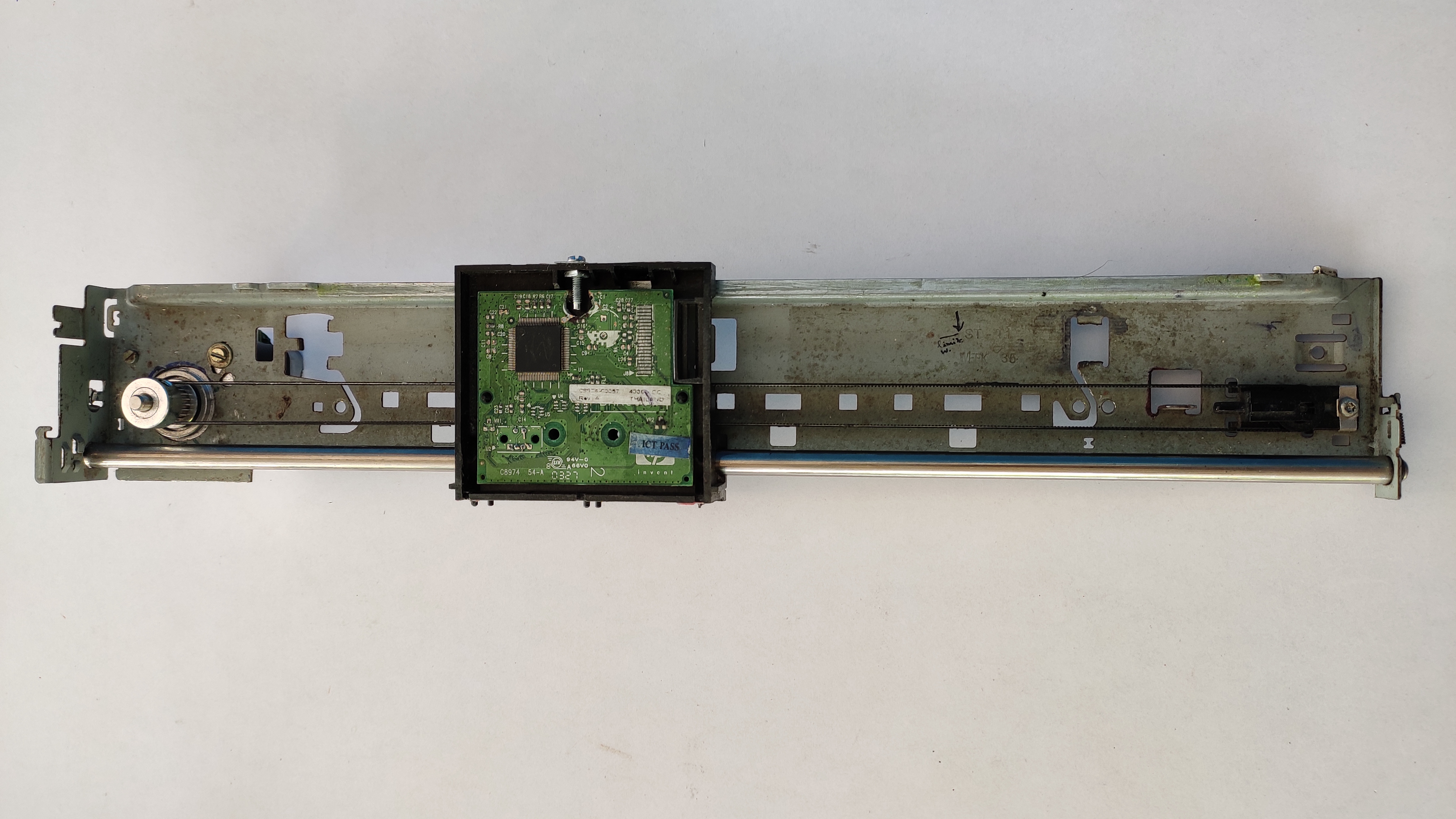
Next, I have recycled some parts of the old printer. I took printer's ink rail system for this step. so this can be used to move in x+ and x- direction.
If you are taking these same parts, please clean the frame thoroughly, cut the raise parts in it because it may collide with the rail travel.Insert the smooth rod into it make sure that all the track of the platform are inserted, Remove the old DC motor from the frame, Apply some oil on the rod if needed.
Attaching Stepper to X Axis Frame:
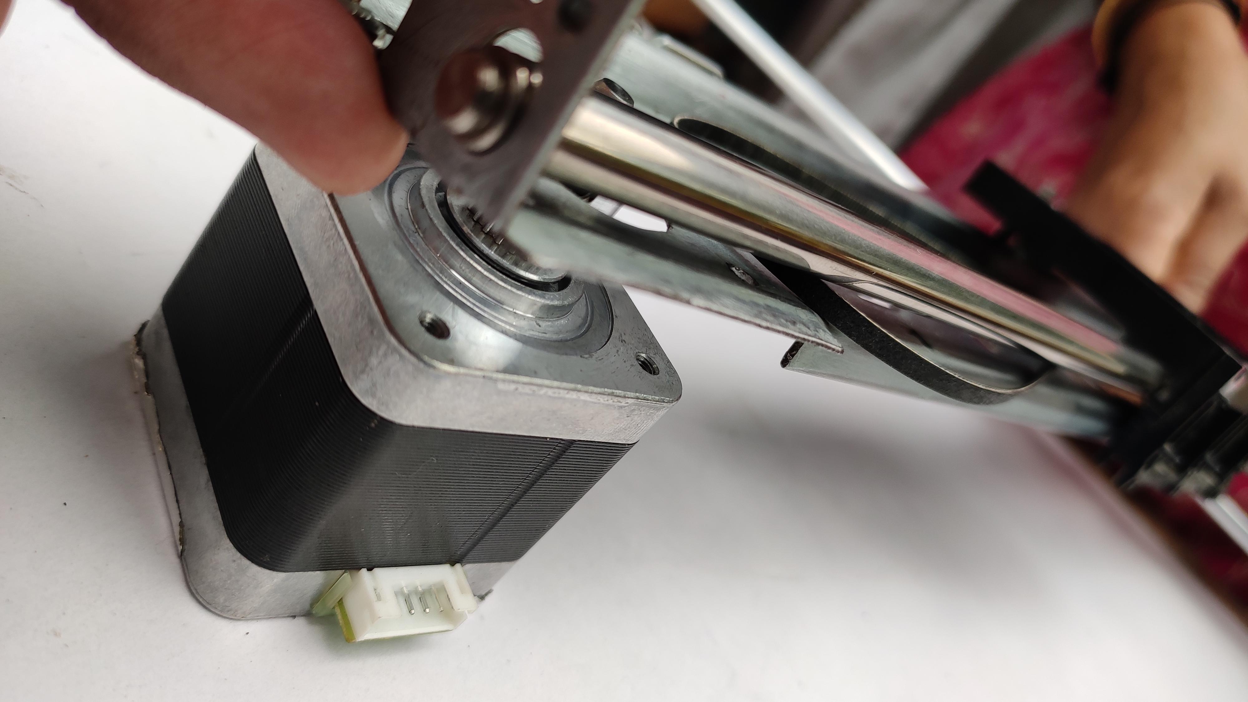
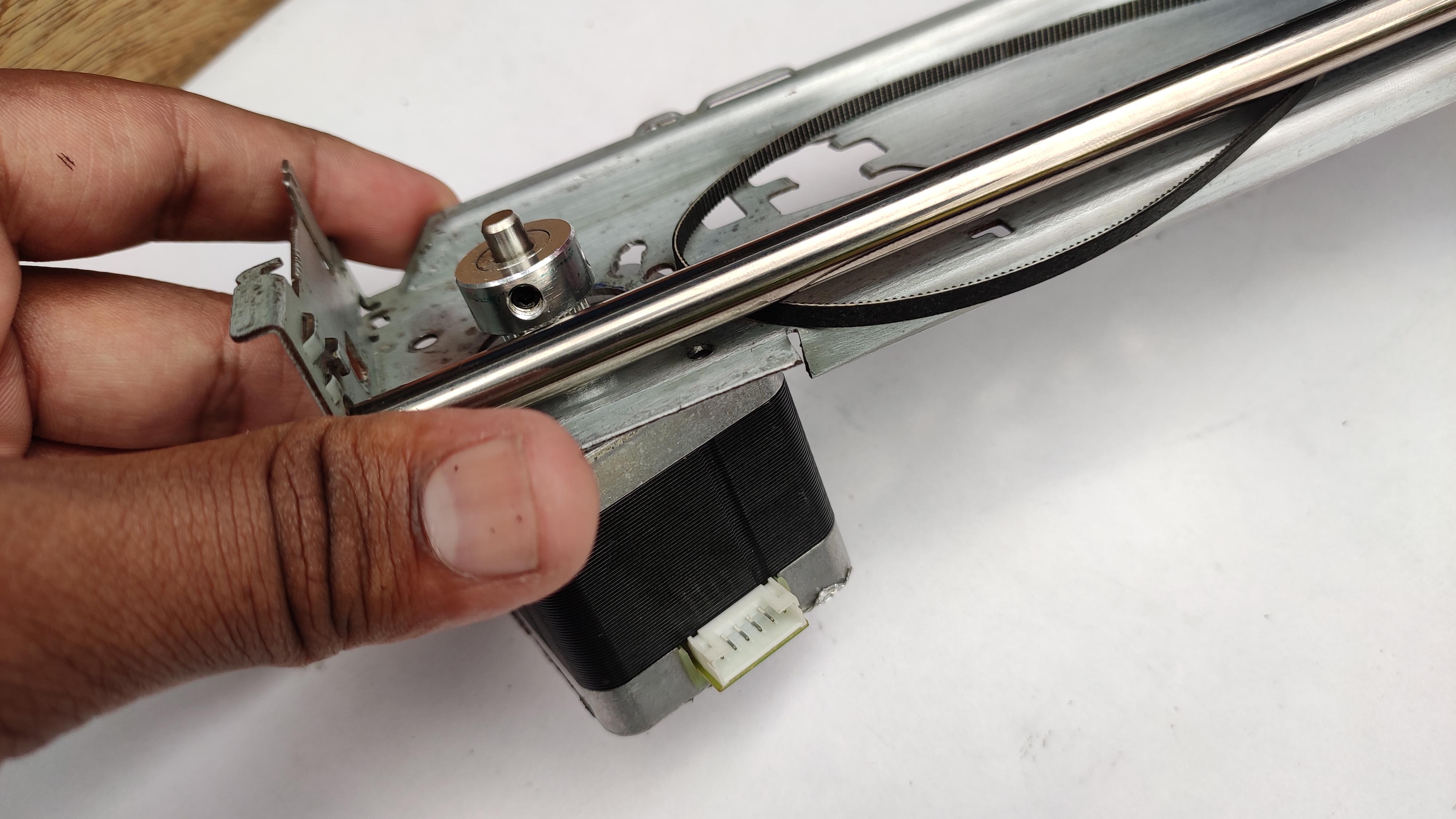
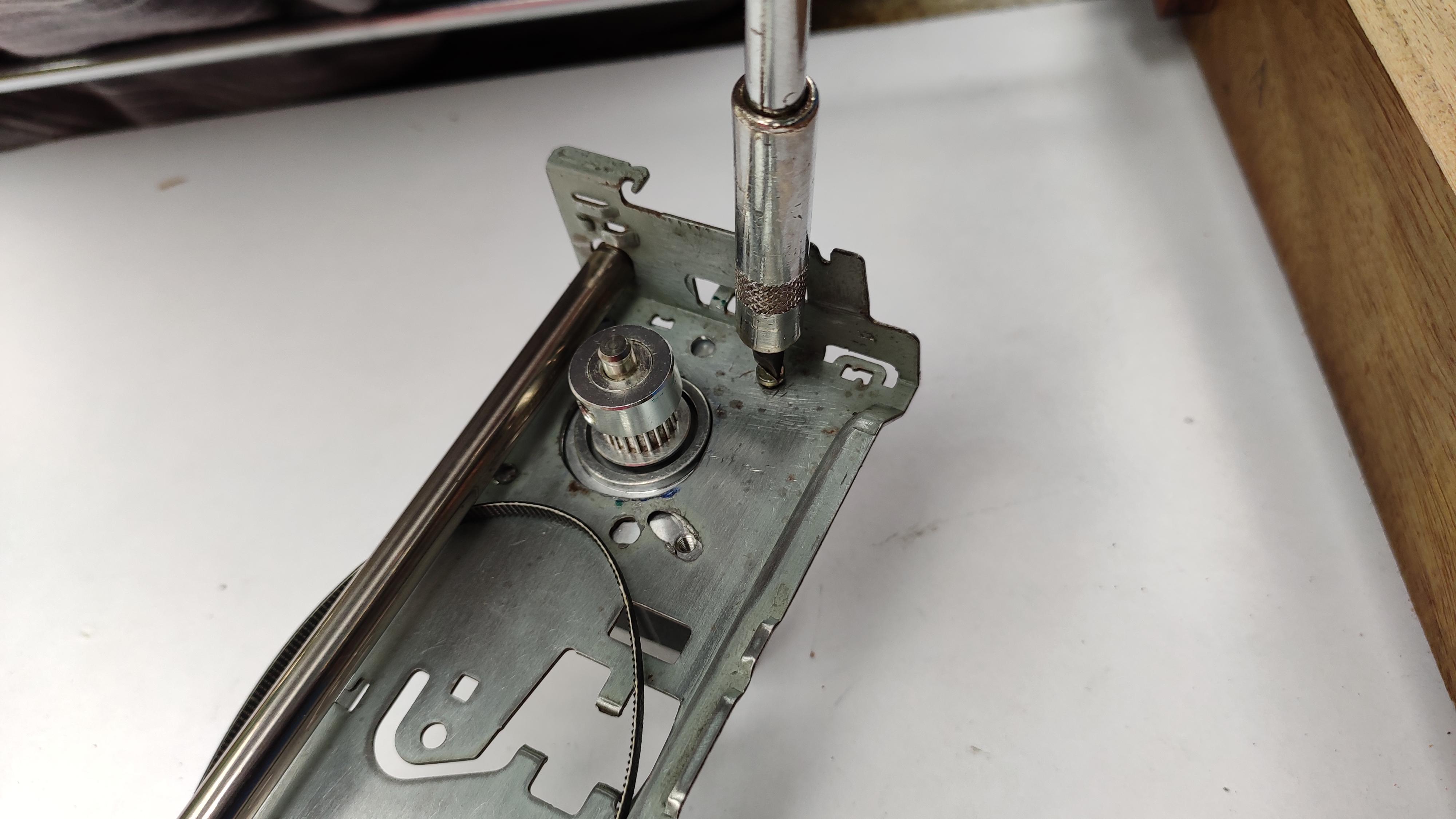
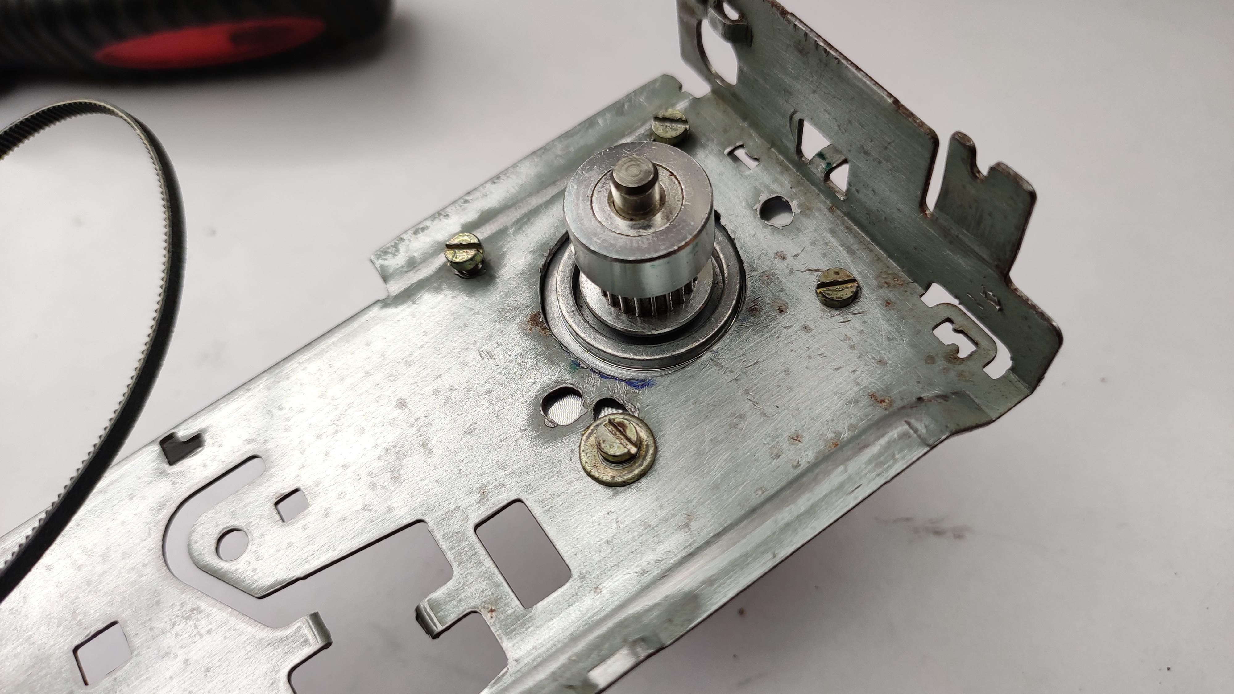
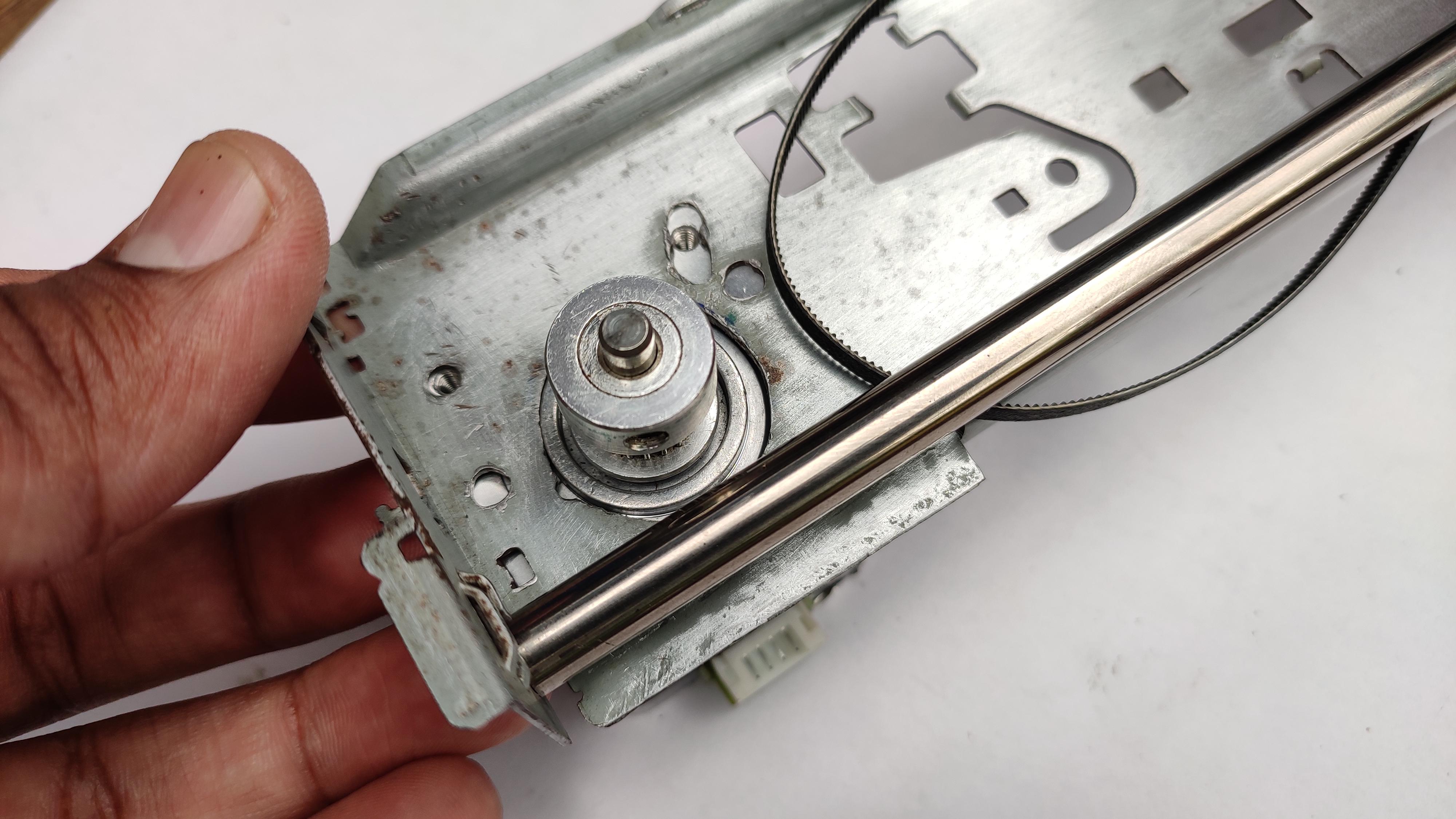
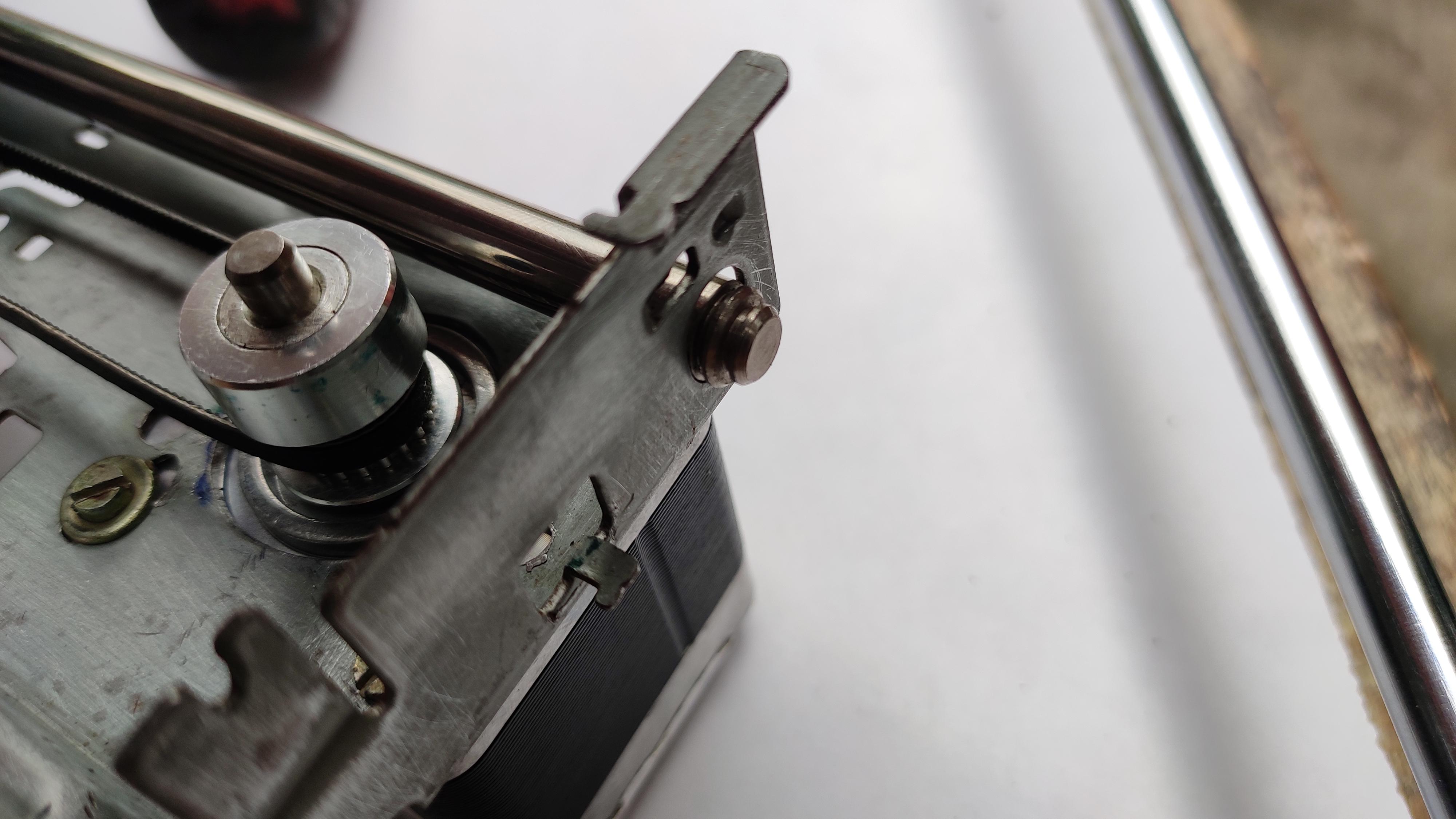
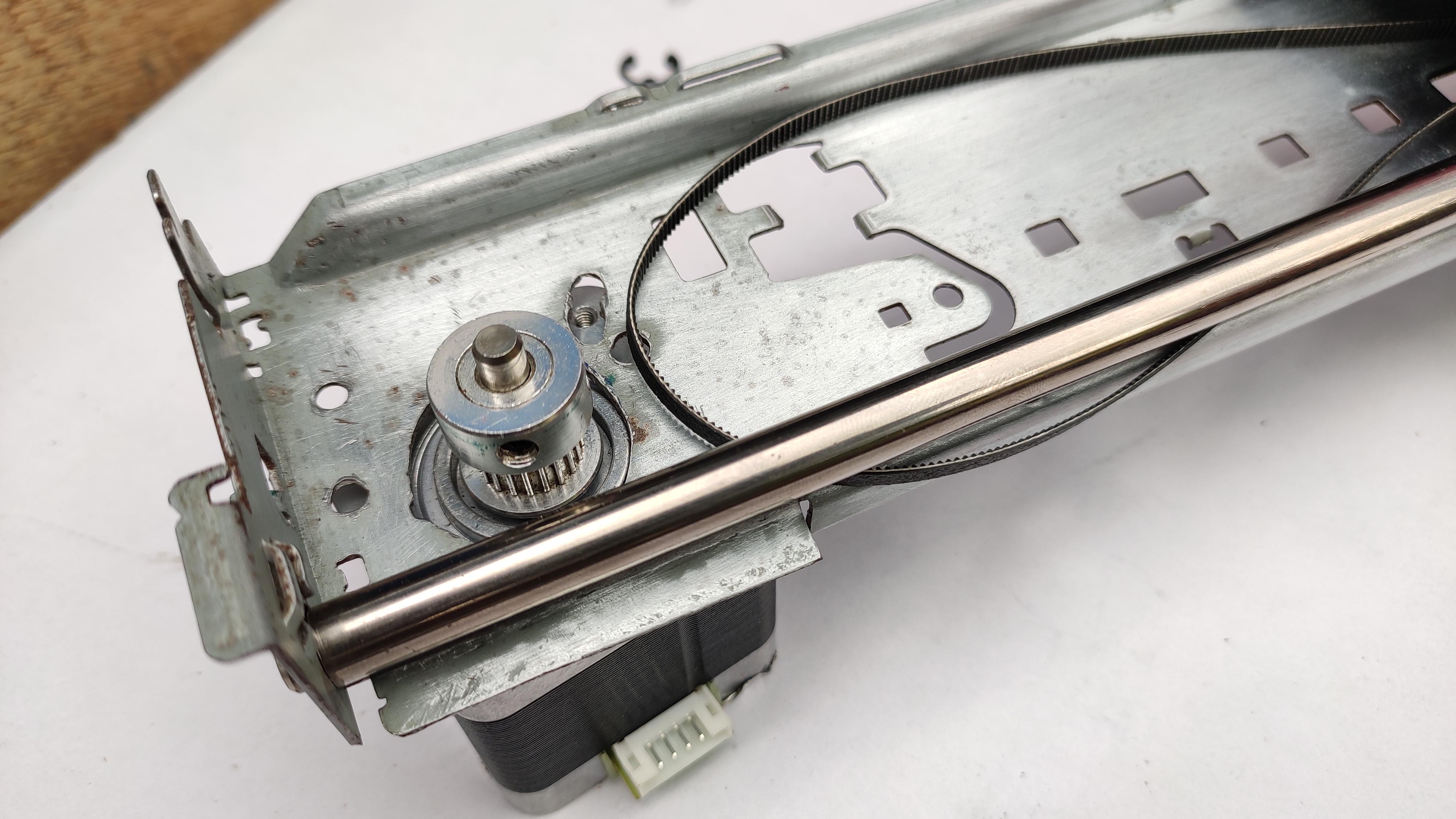
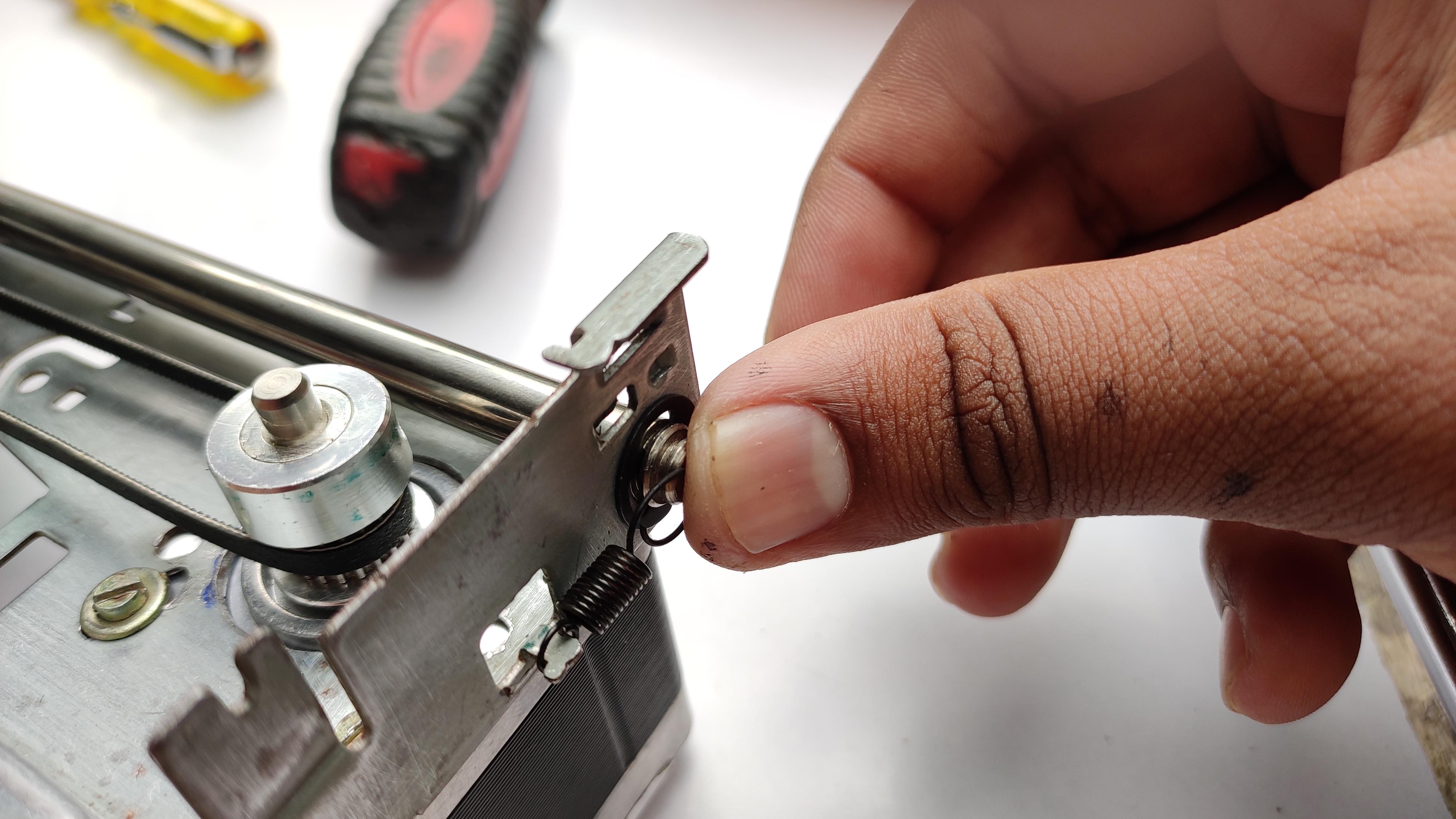
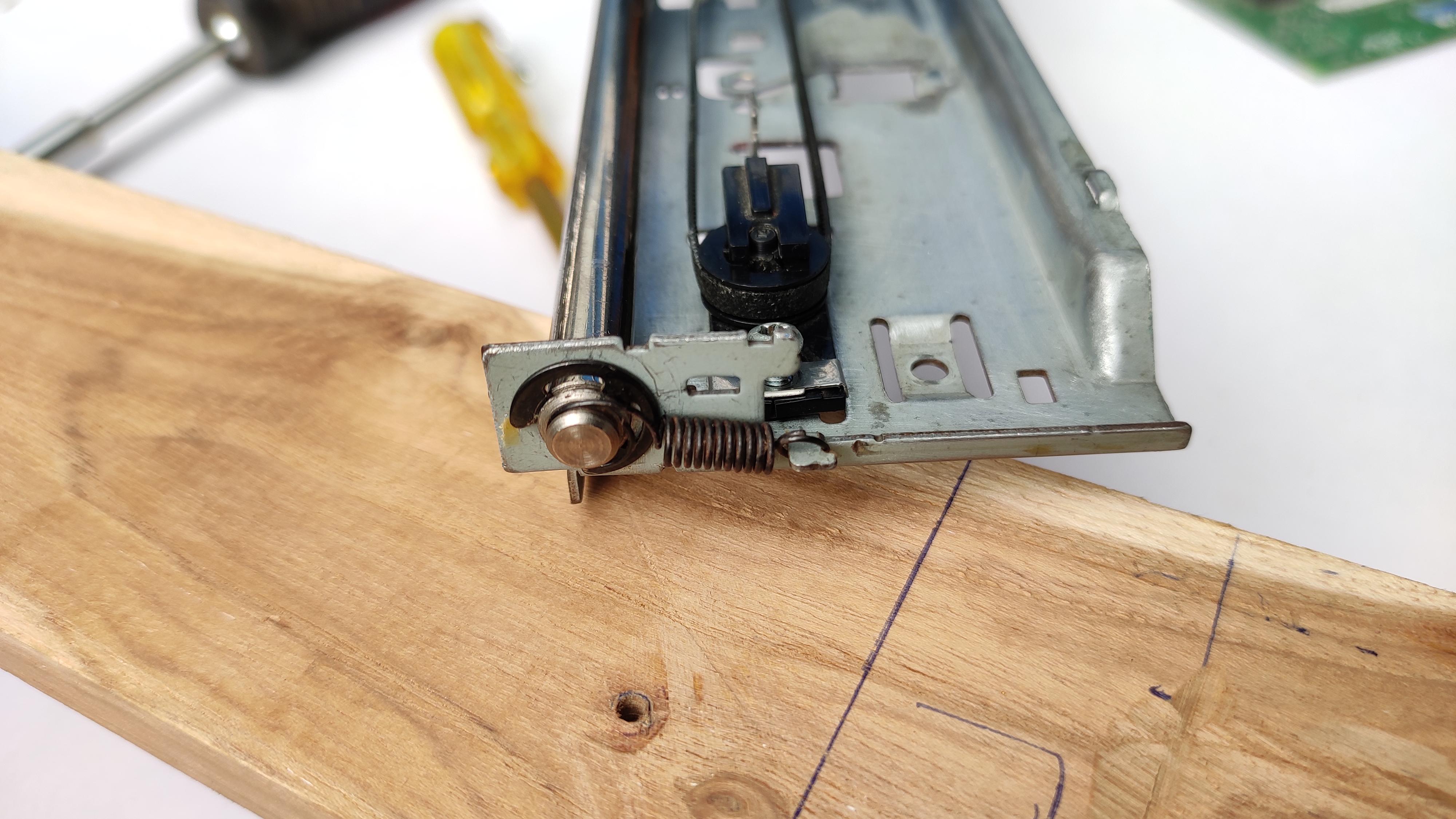
Attach the stepper motor properly on the frame. place it on the position of your convenience for wiring.
Attach belt to the pulley which is fixed with the motor and one on the other side, do put the cir-clip/spring on both the sides of the rod. Make sure that the belt is decently tight, because it may affect the plotting results.
Fixing X- Axis to the Wooden Platform
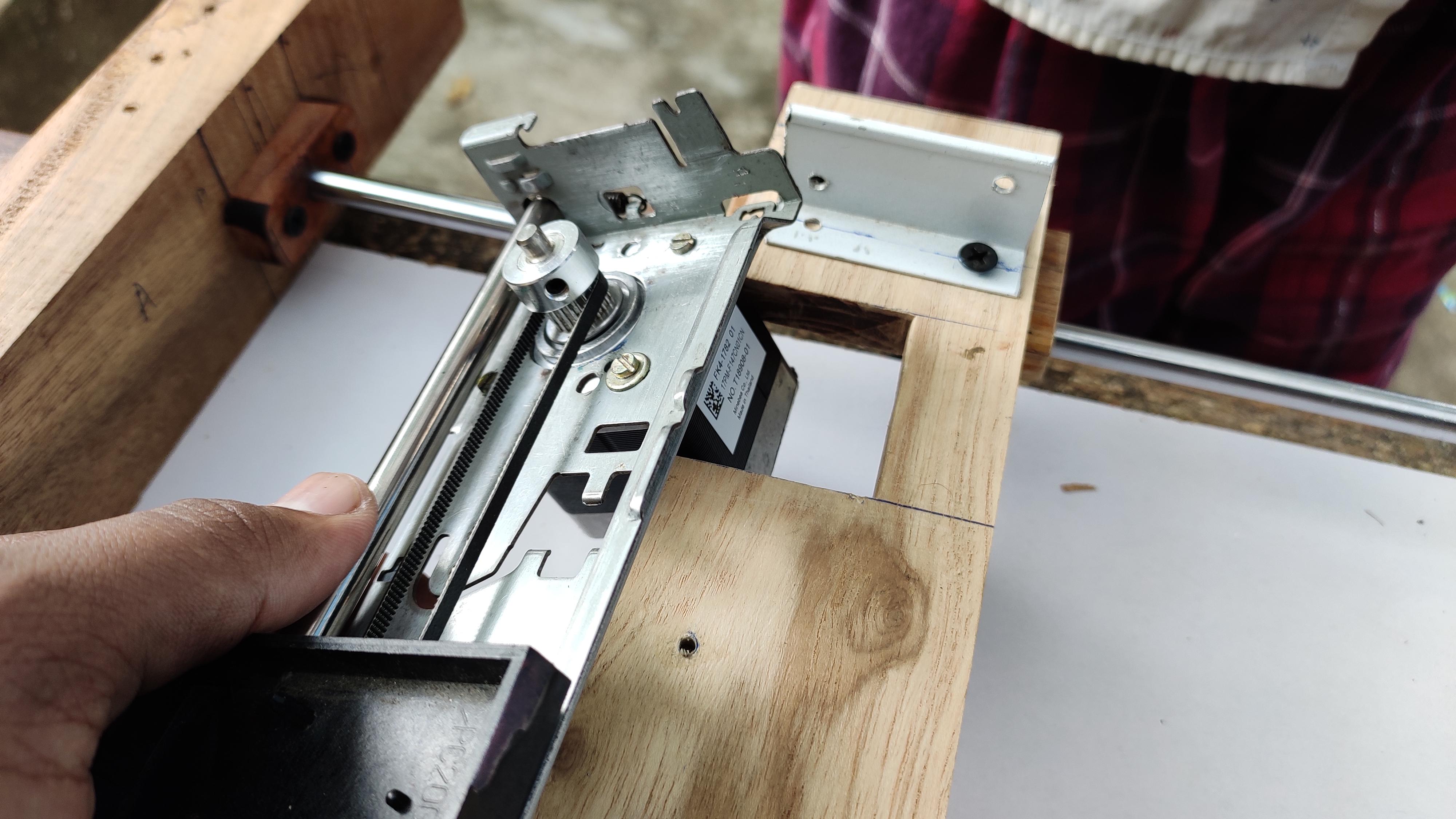
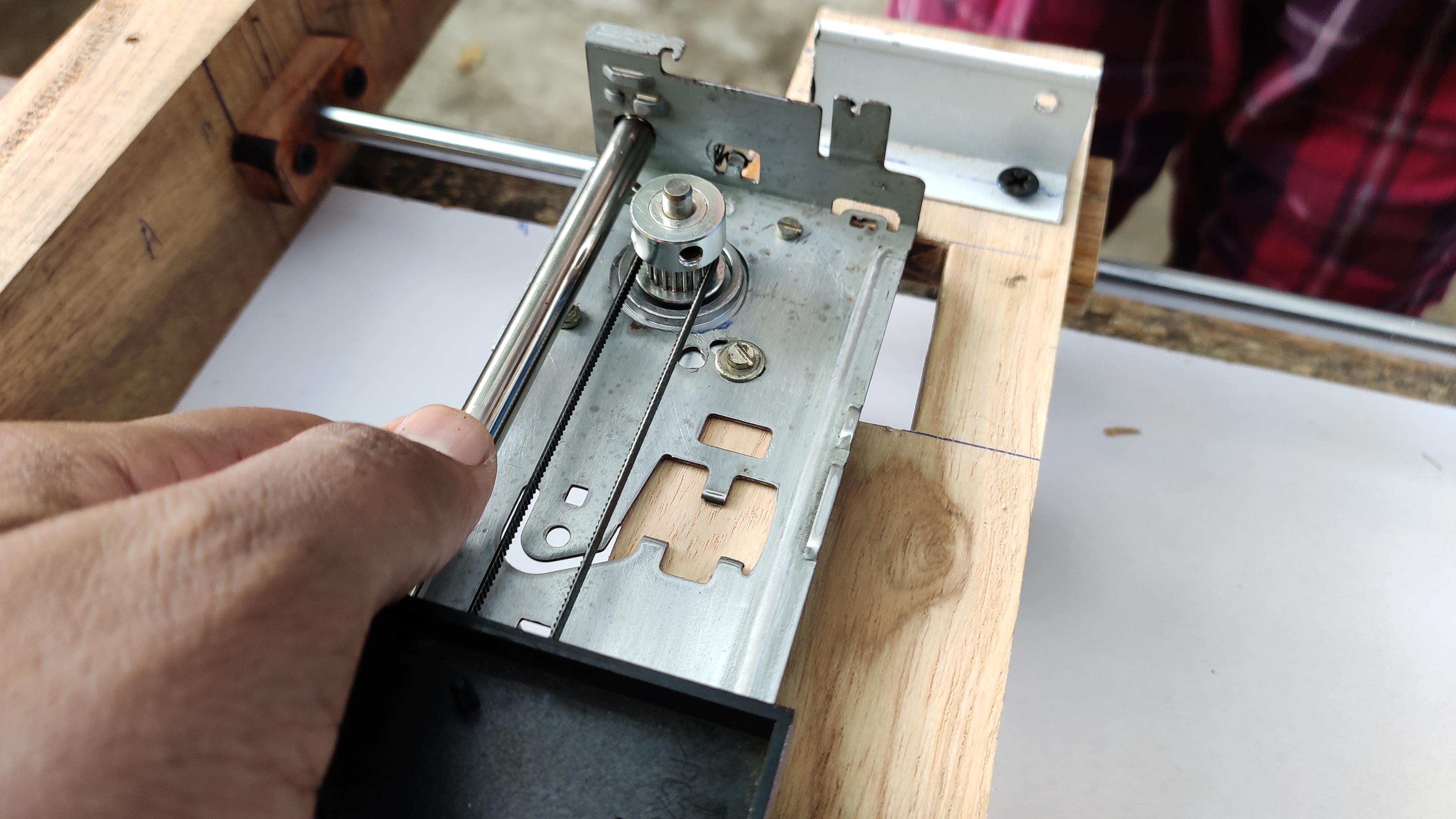
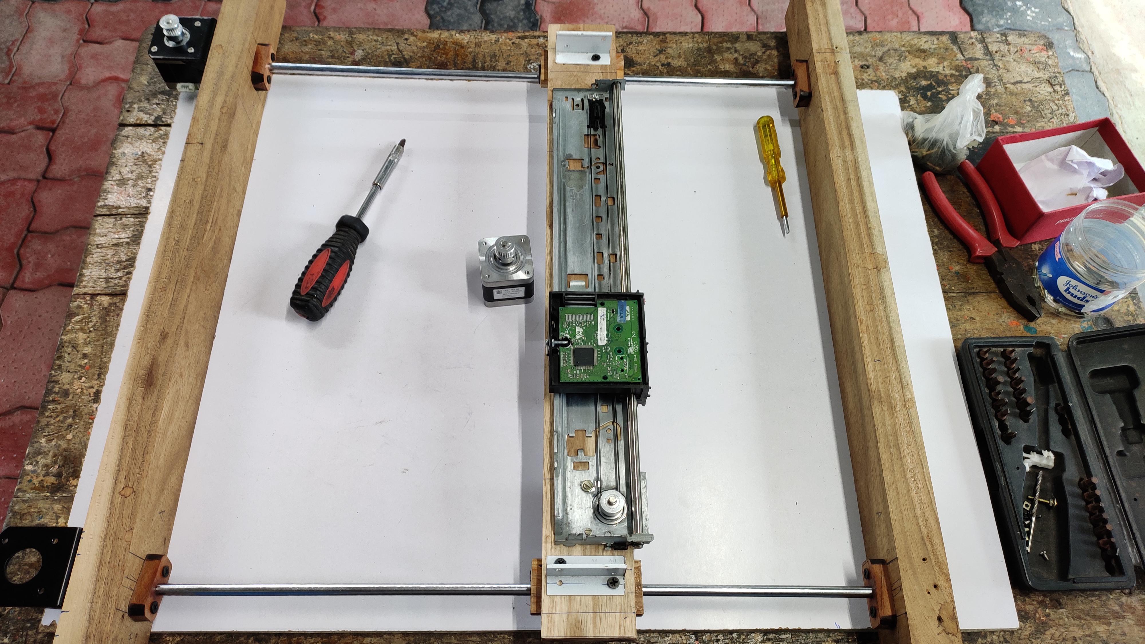
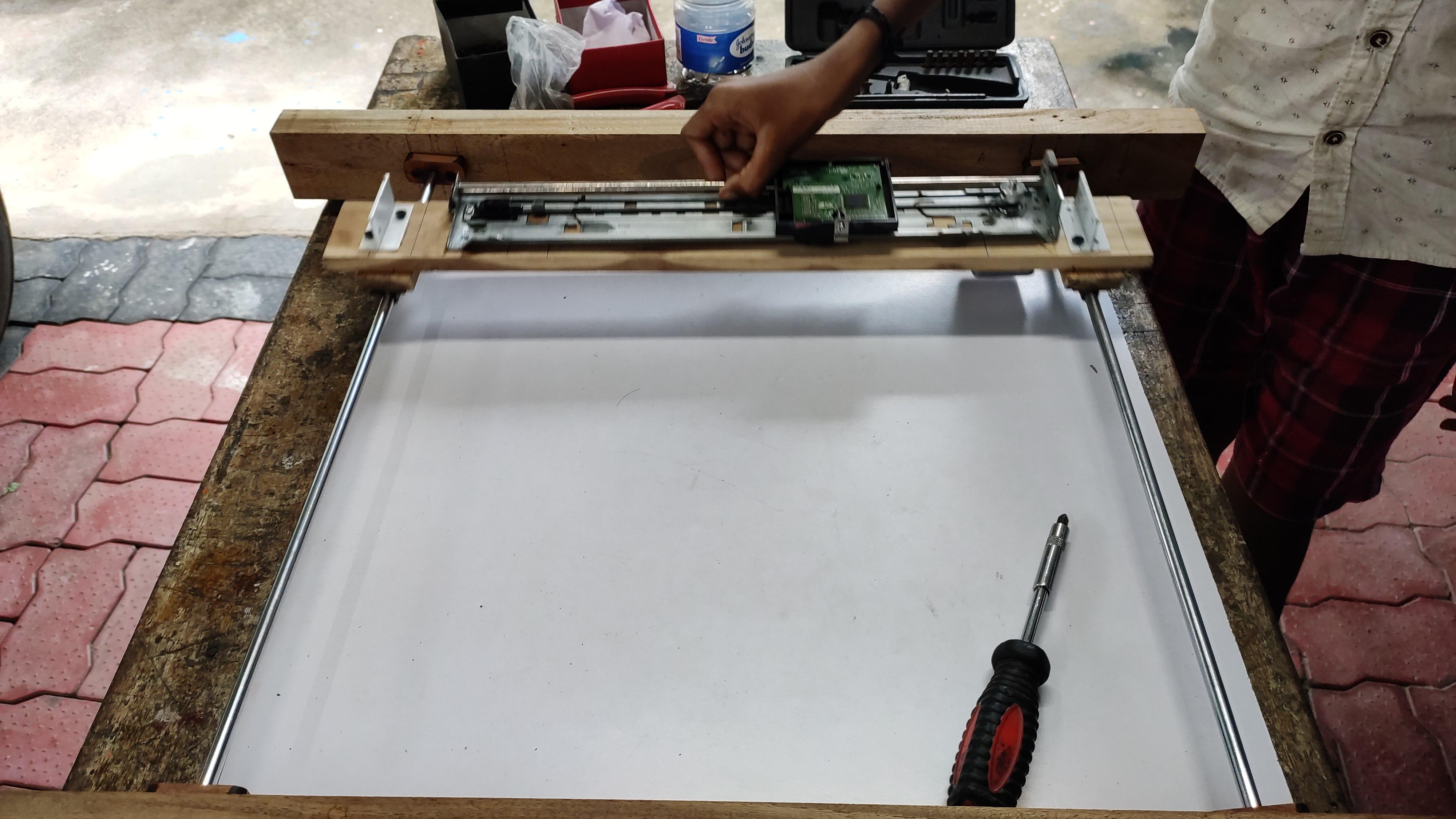
Carefully place the X-axis linear rail on the platform which we had set already. Screw it, tight it.
Make sure the travel platform moves smoothly in x+ and x- direction, and does not touches any of the wooden parts.
yep, this is an easy step.
Setting Up the Y-axis Stepper Motors
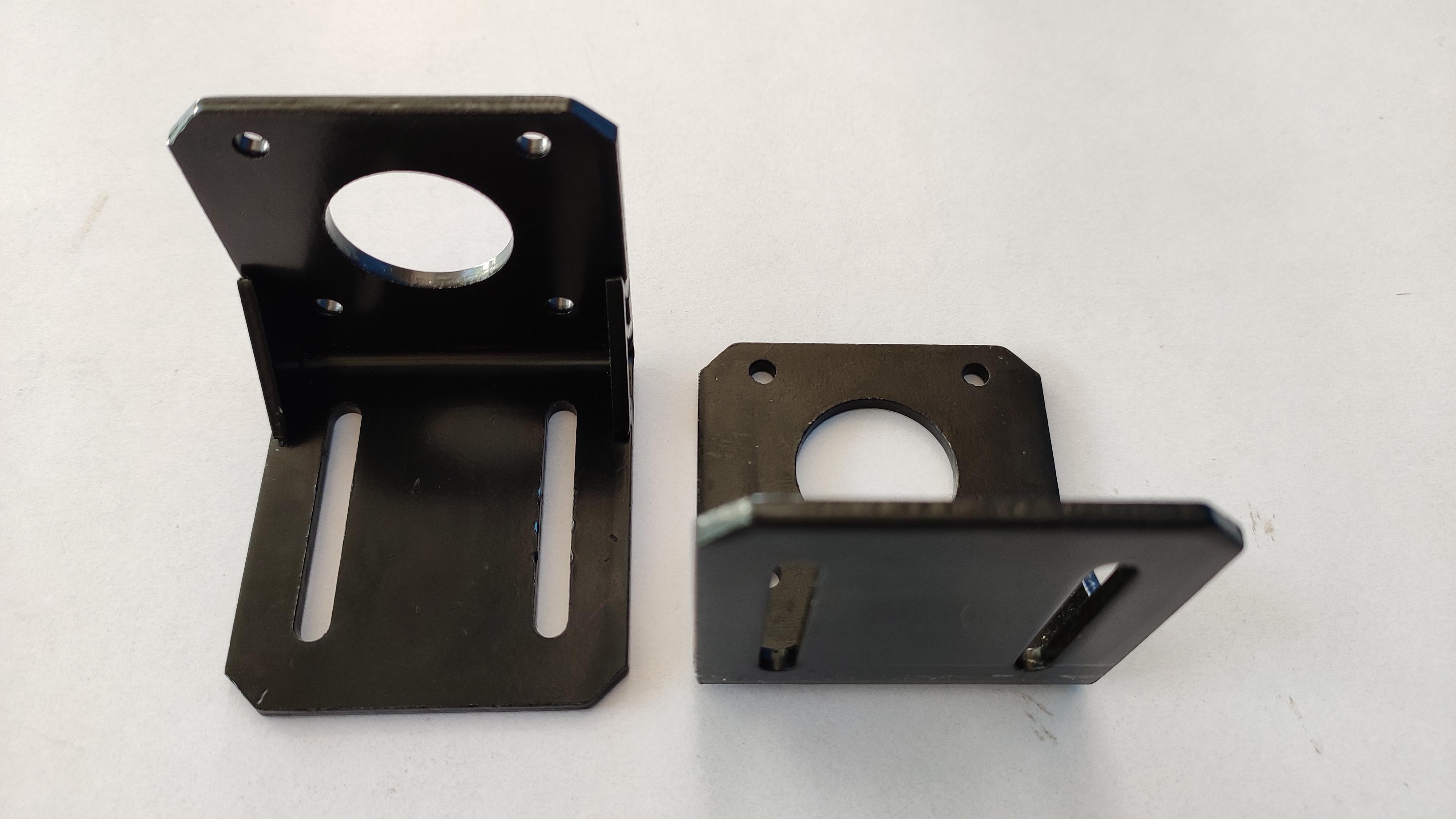
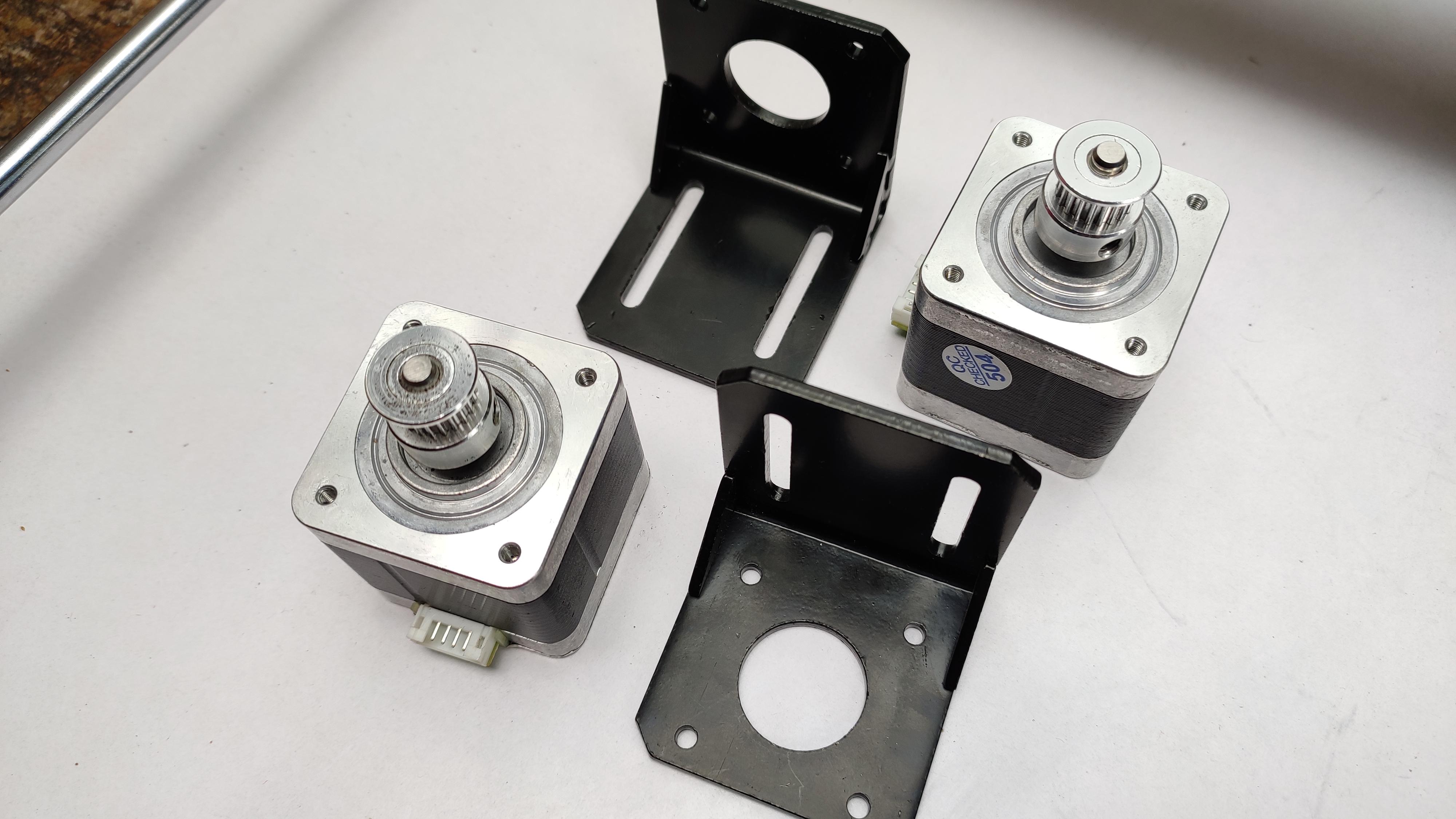
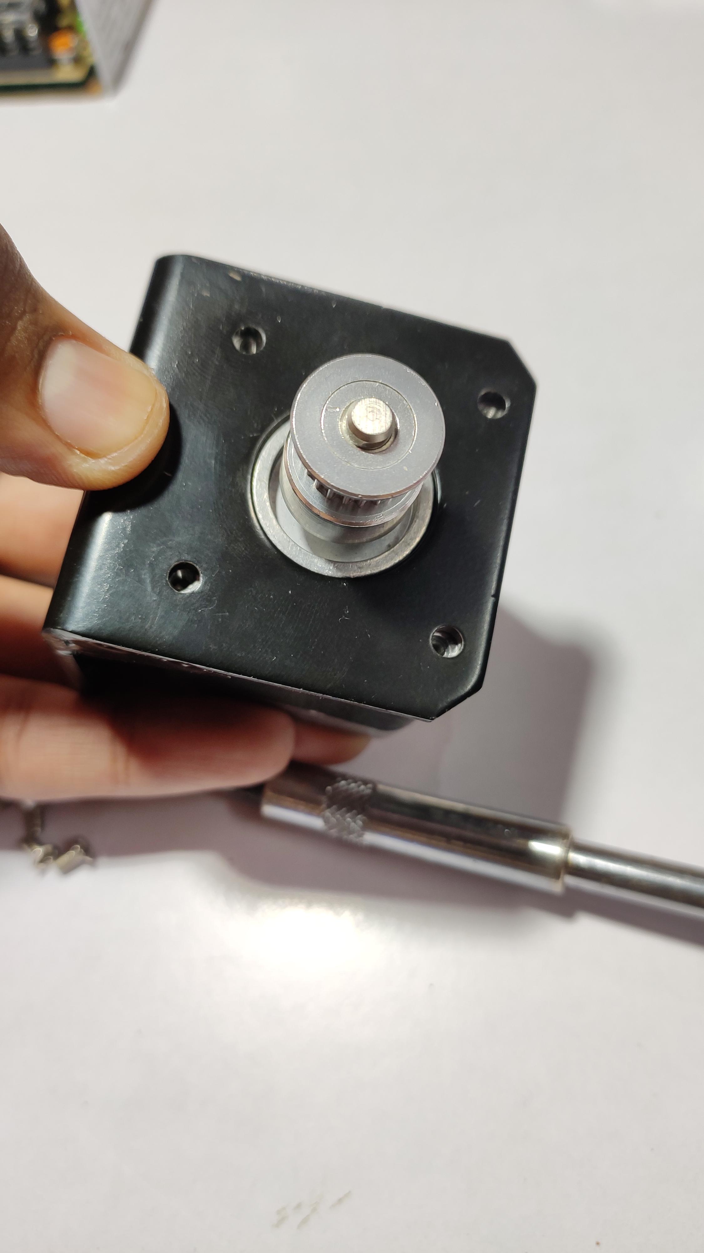
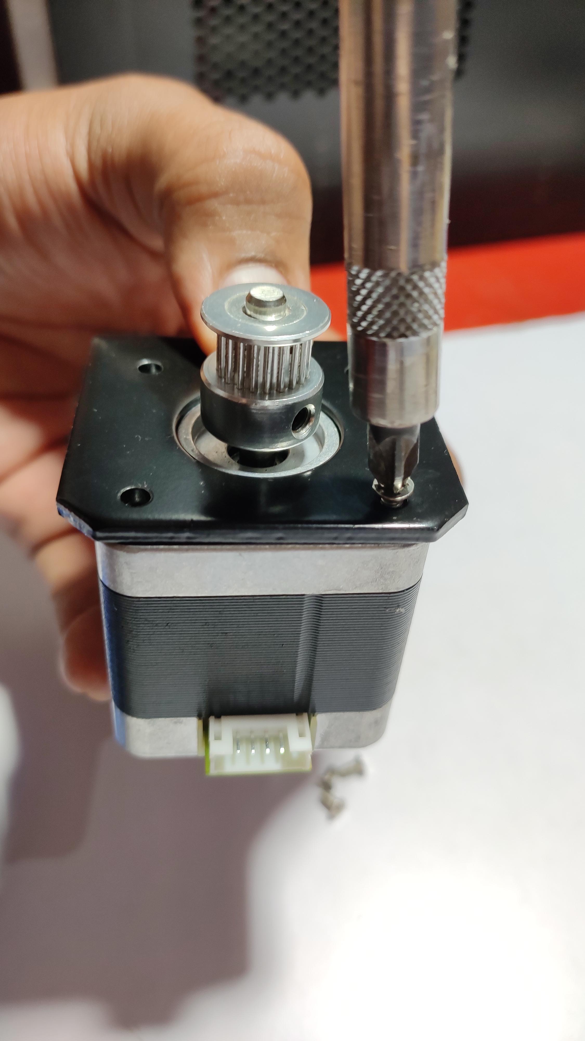
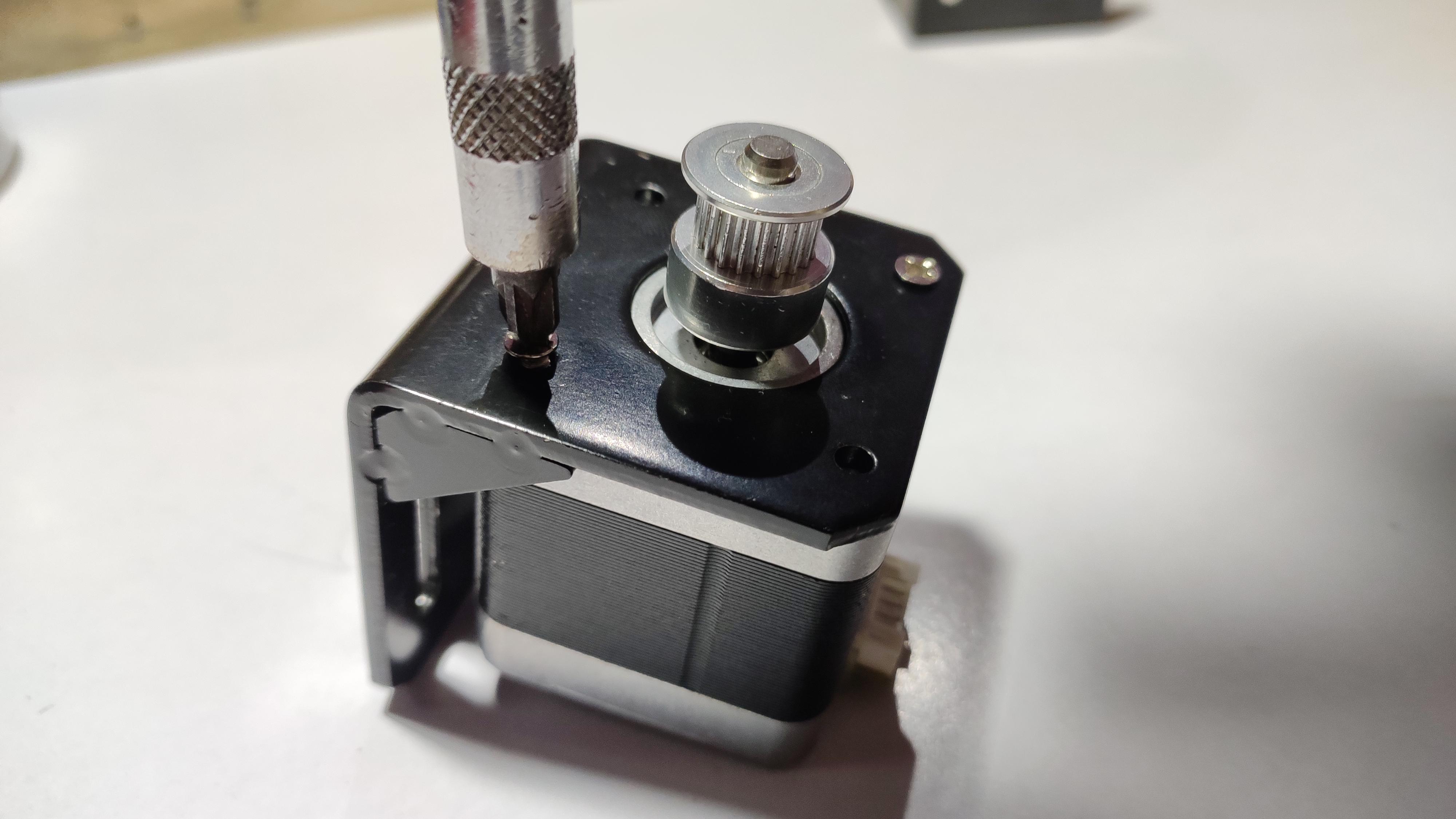
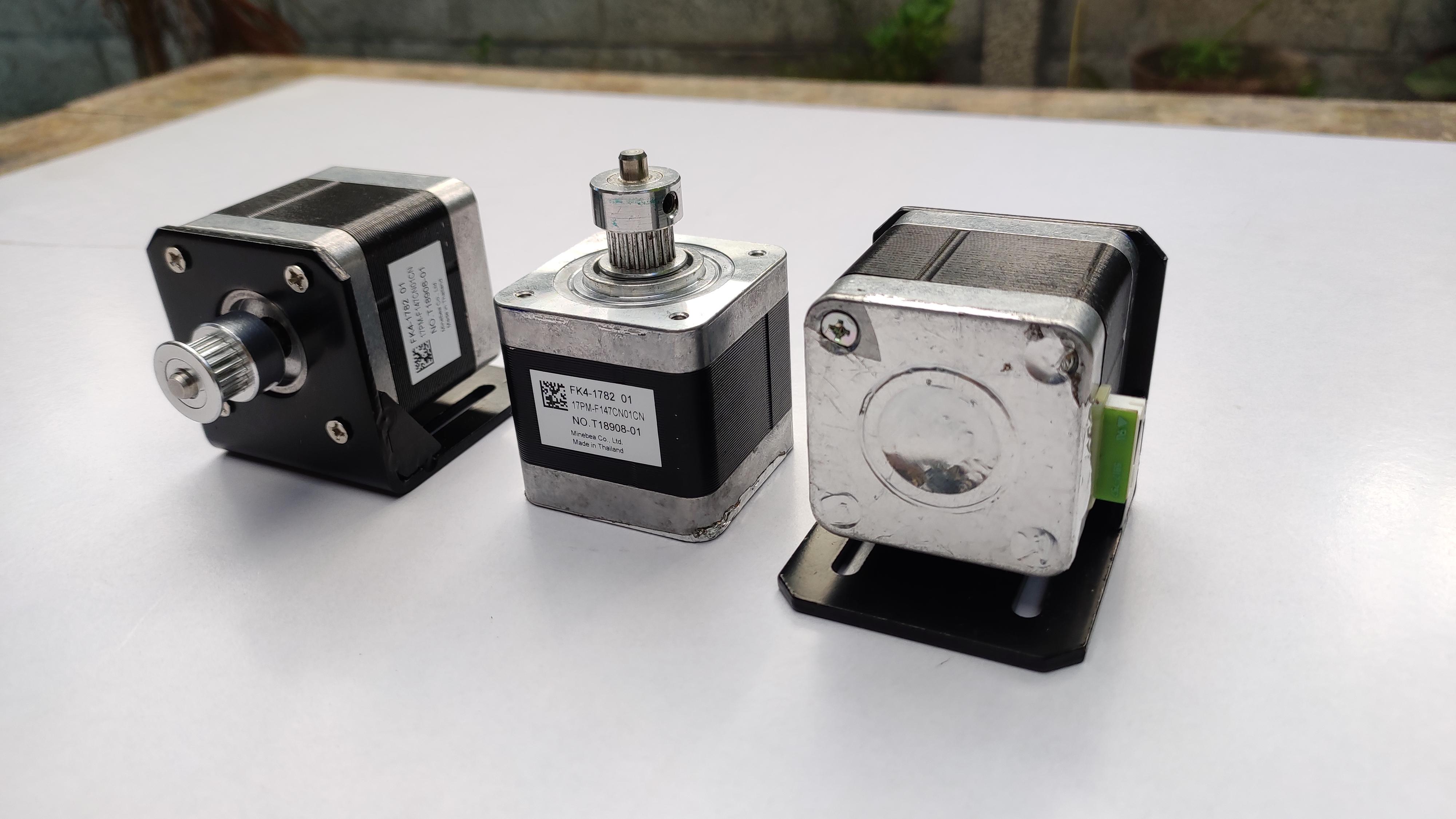
Well, this too is any an easy step. We are setting up the other two steppers for the Y-axis.
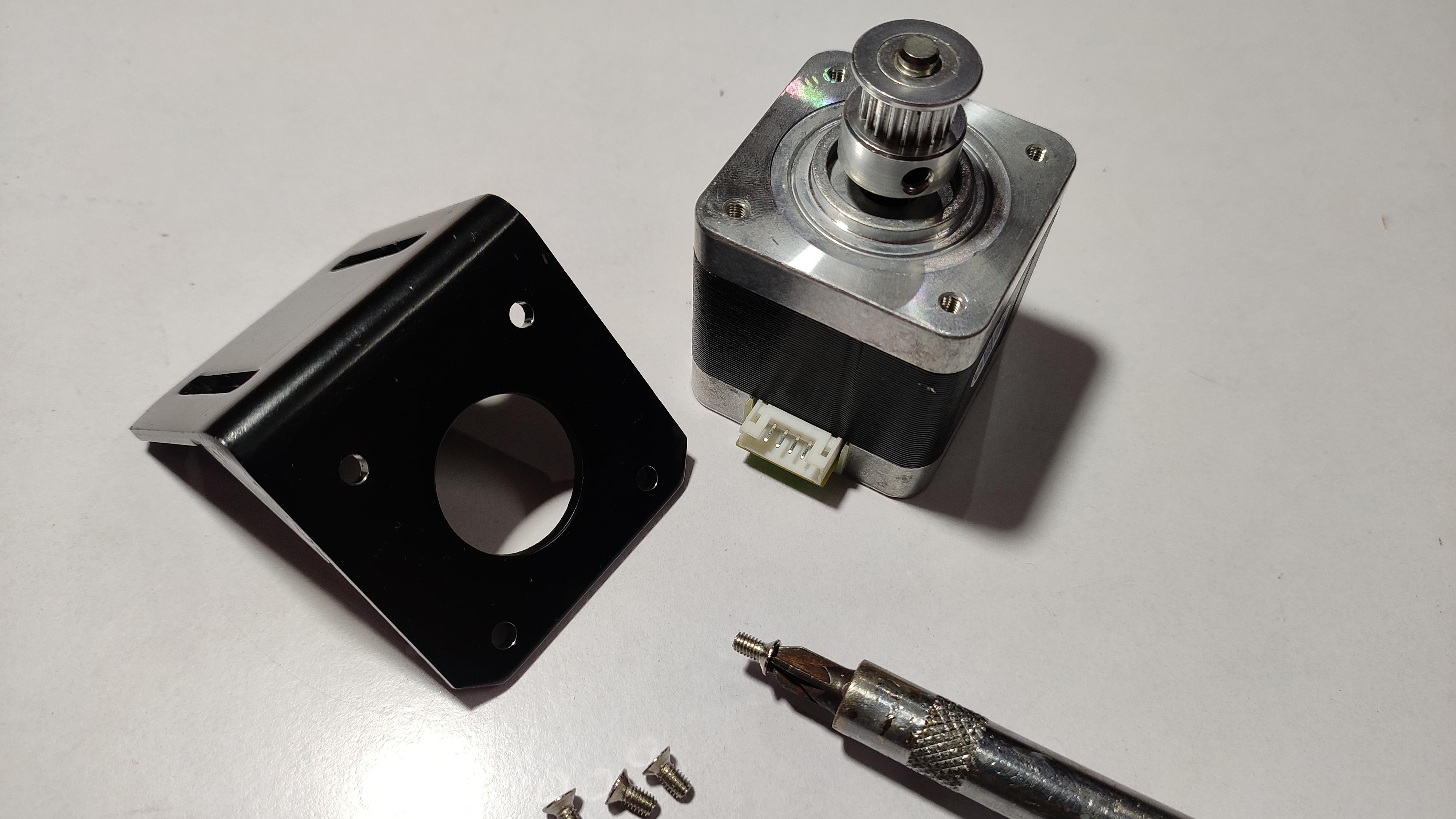
we need two Nema 17 stepper motor, two l bracket compatible to Nema 17 motor. This step is to make sure that the L bracket is correct 90 degree and stepper fits to it properly.
So we can ensure the good motion of the x platform in y+/y- directions. If you are satisfied with these supplies remove all of them, faaaasssttttt move on to the next step :)
Adding Y-Axis Steppers to the Frame:
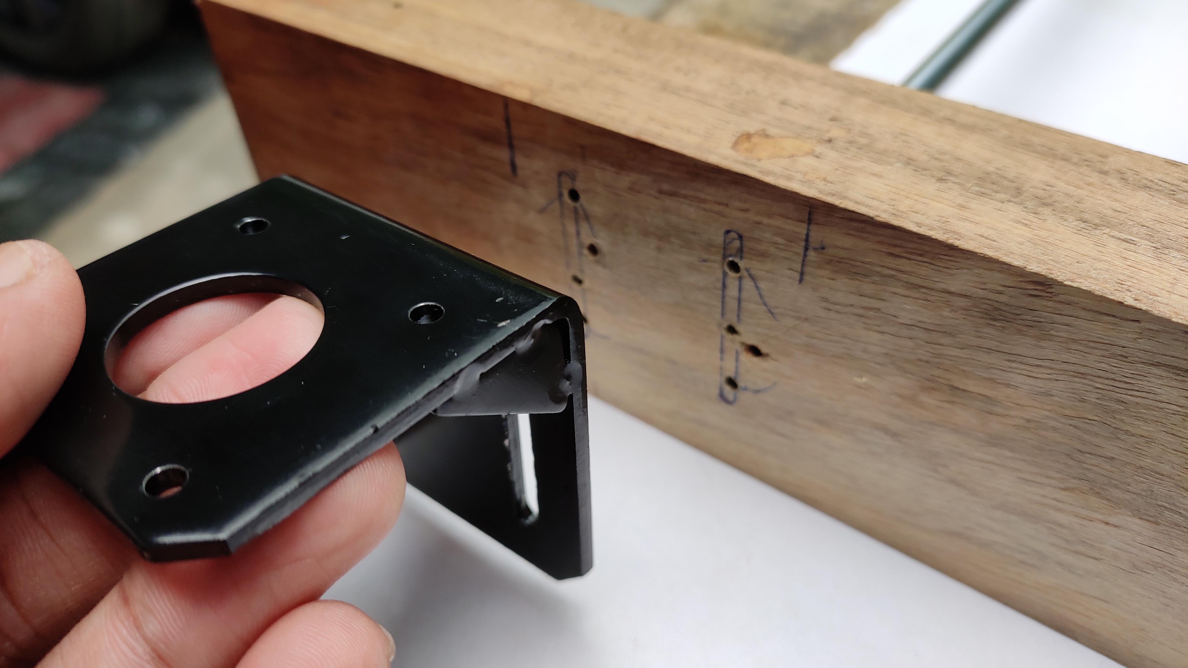
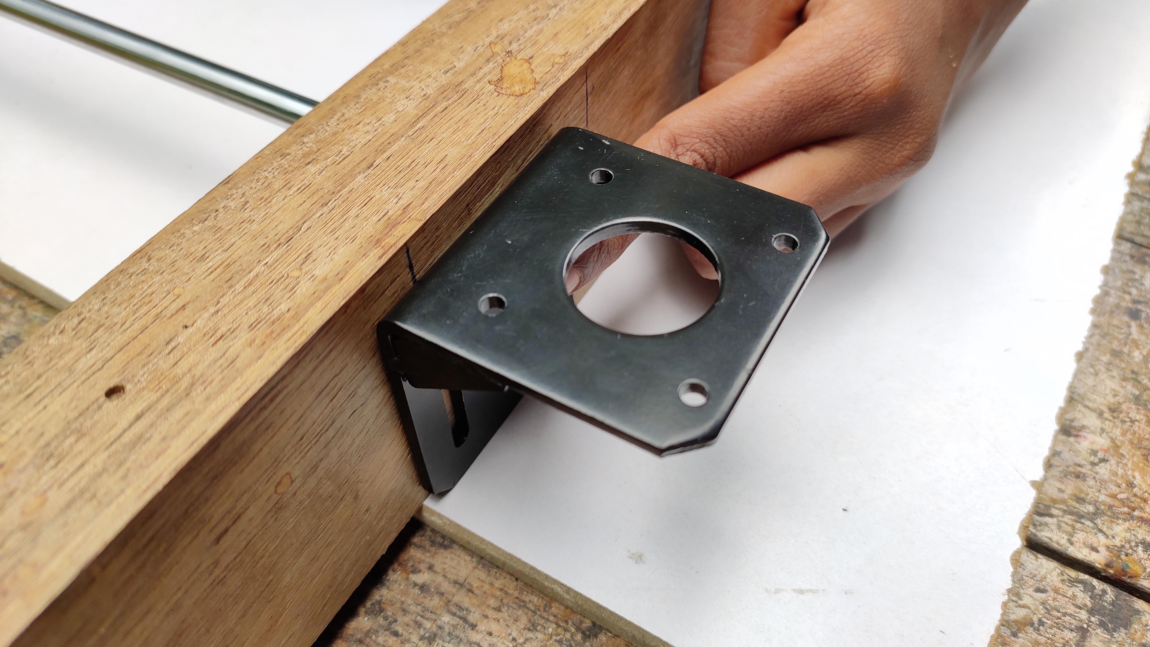
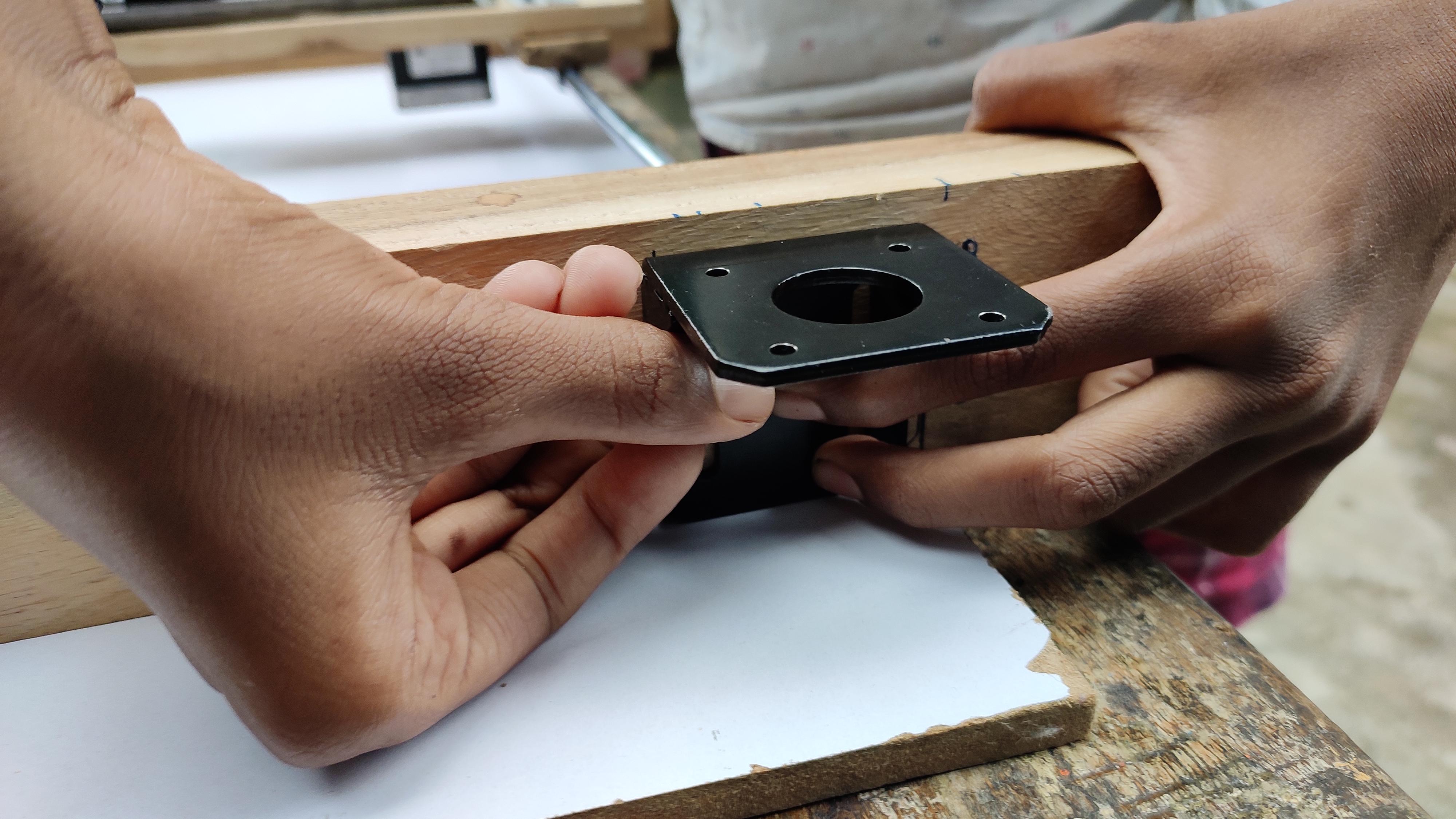
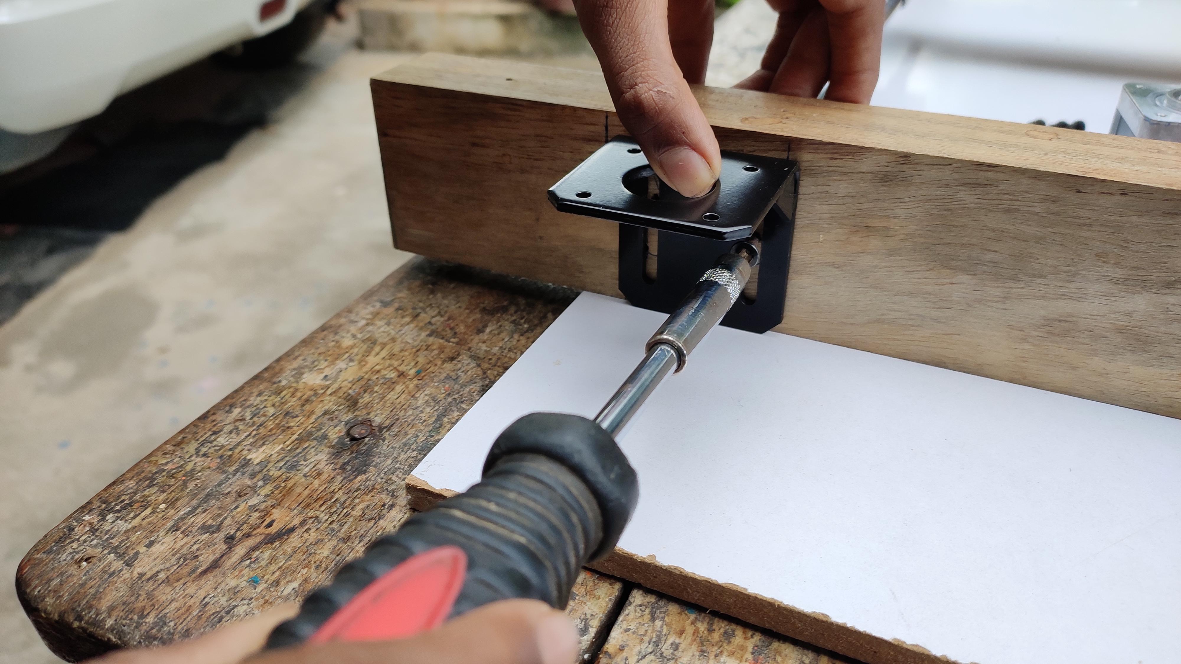
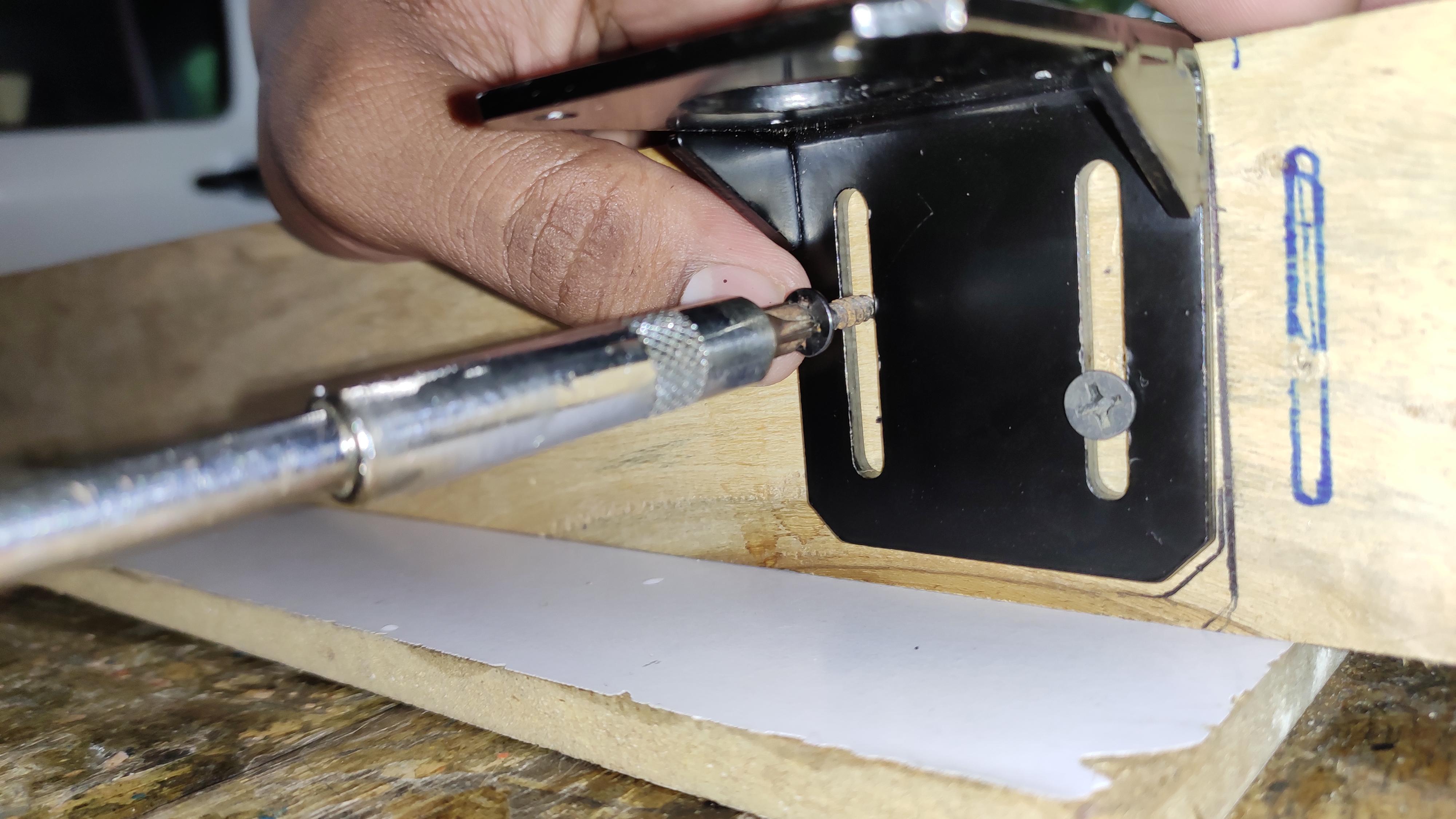
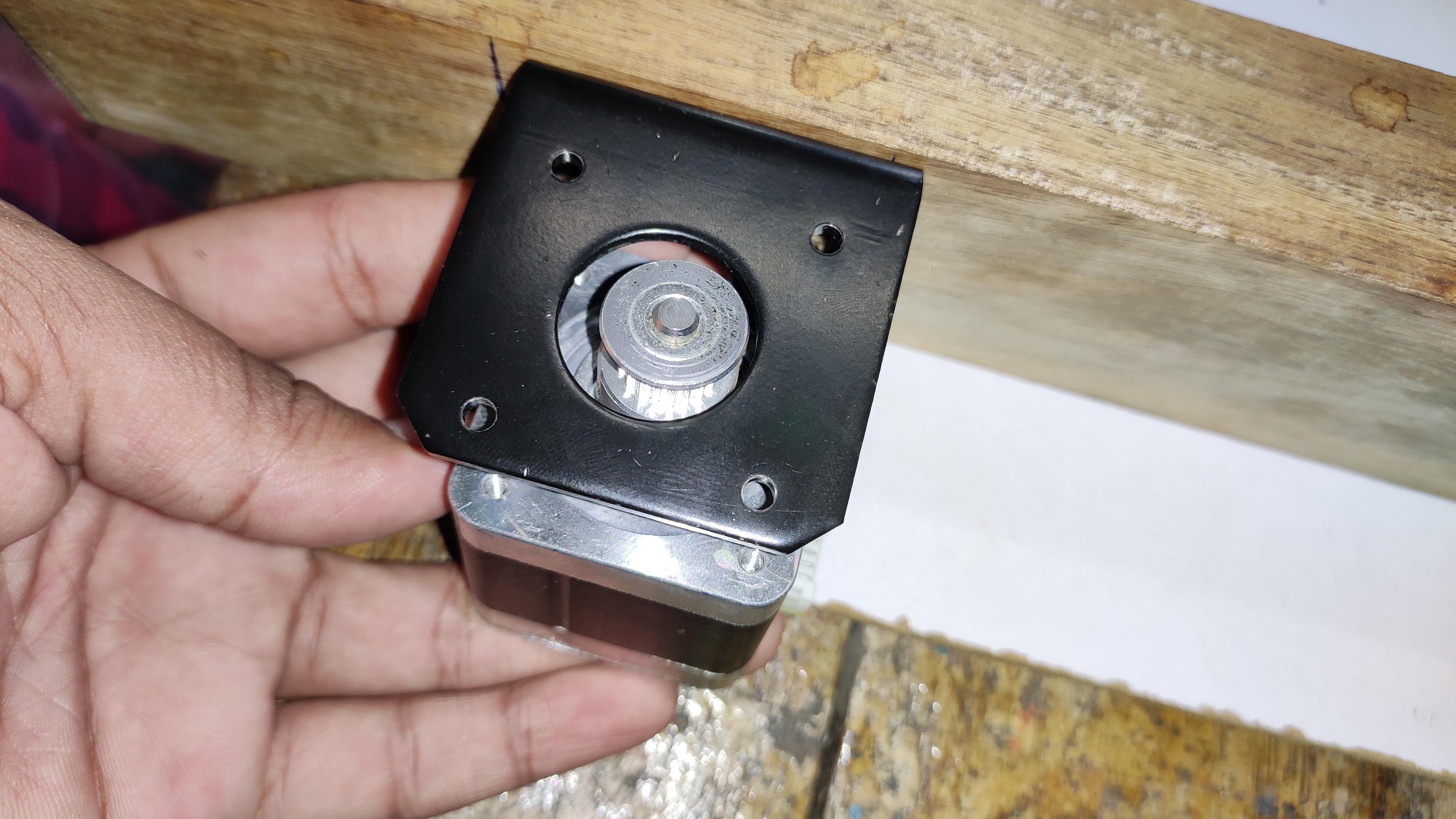
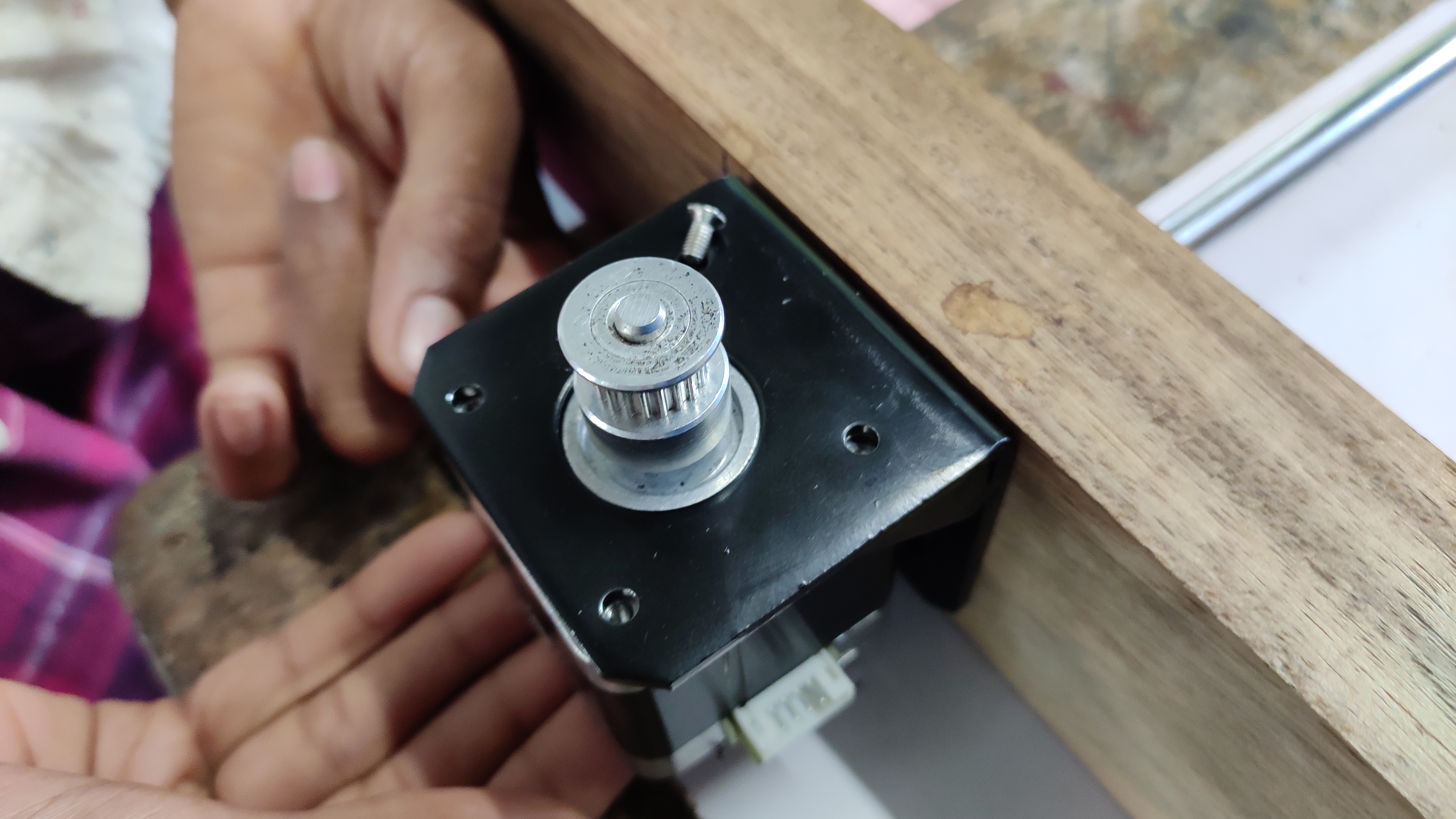
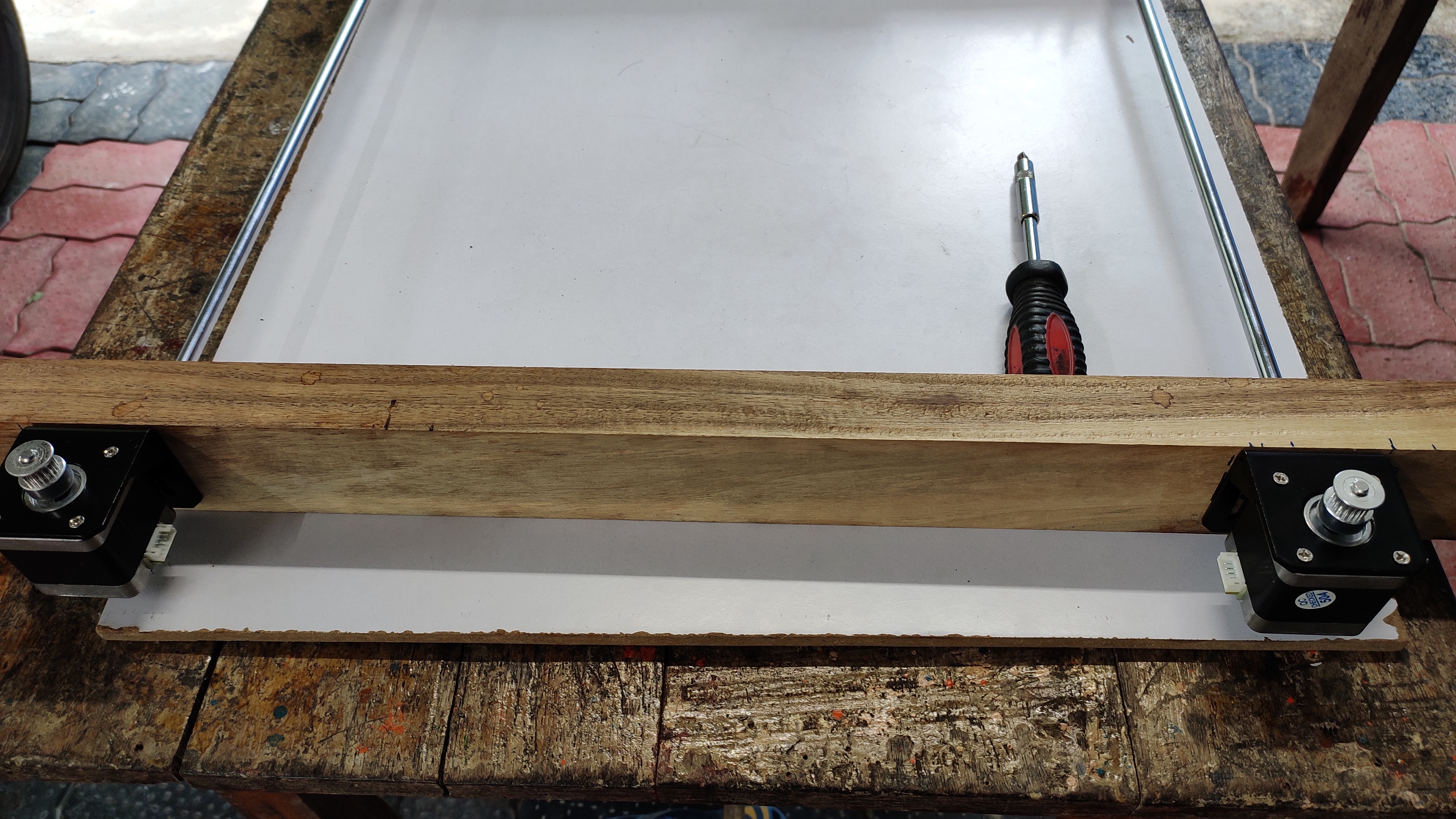
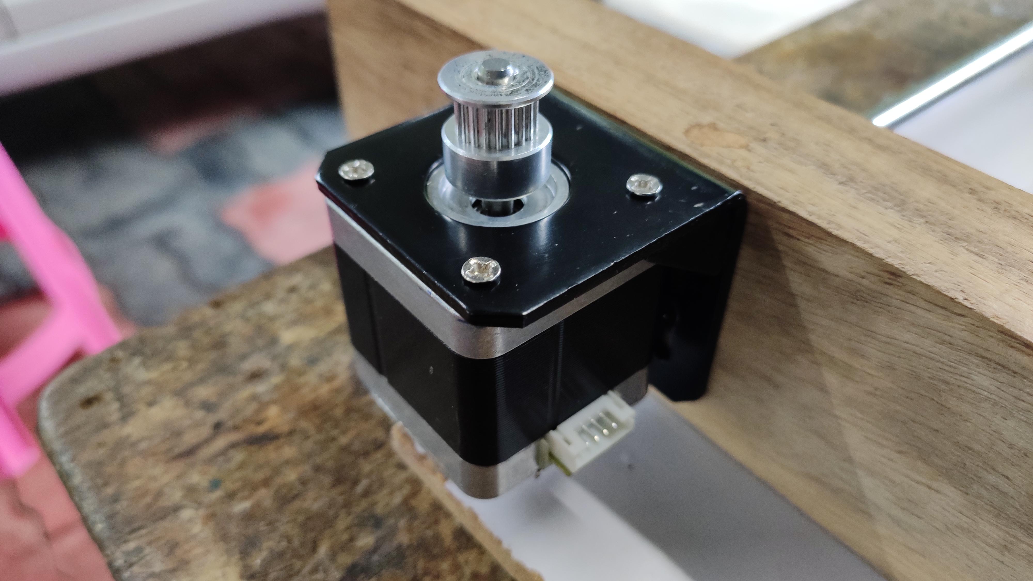
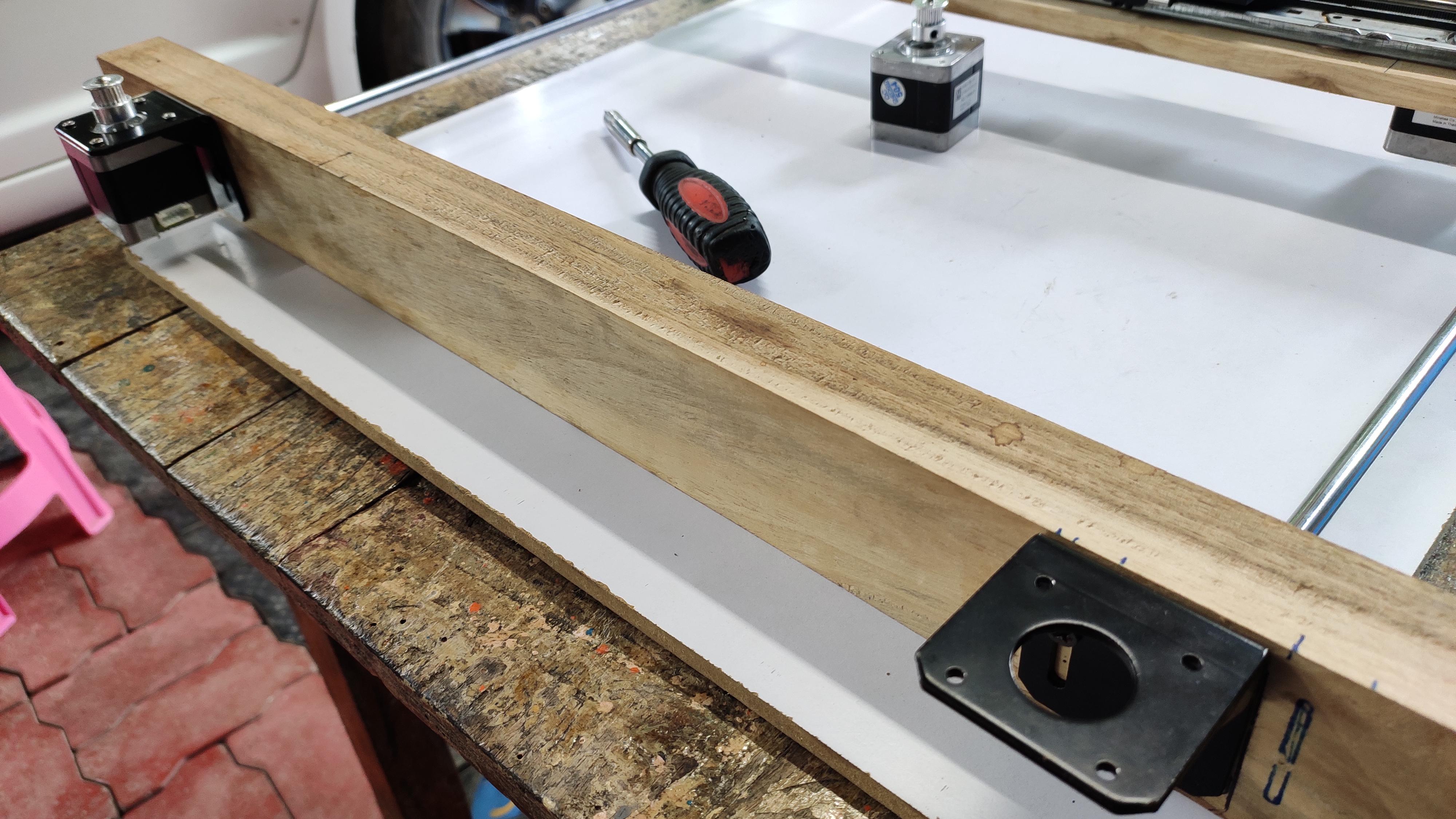
This step will guide you to fix the y-Axis stepper motor to the wooden frame. At first, fix the L bracket to the frame, ensure it is fixed straight to the belt holder. Carefully tight all four screws, because this is also one of the main part of this project... Likely fix the another set of L bracket and stepper on the other side in equal height of the other set, straight to the belt holder of this side.
Setting Up the GT2 Pulley, Wooden Holder -- Attaching It to Frame:
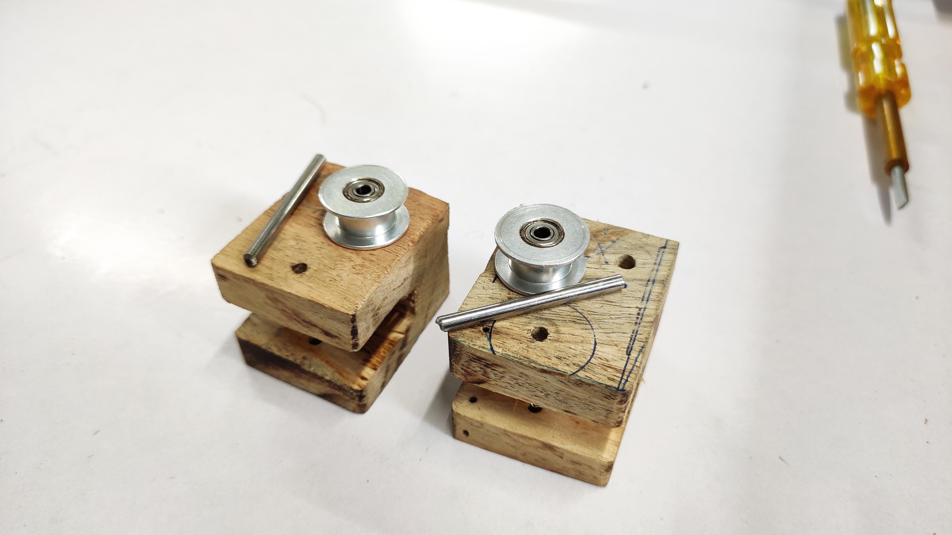
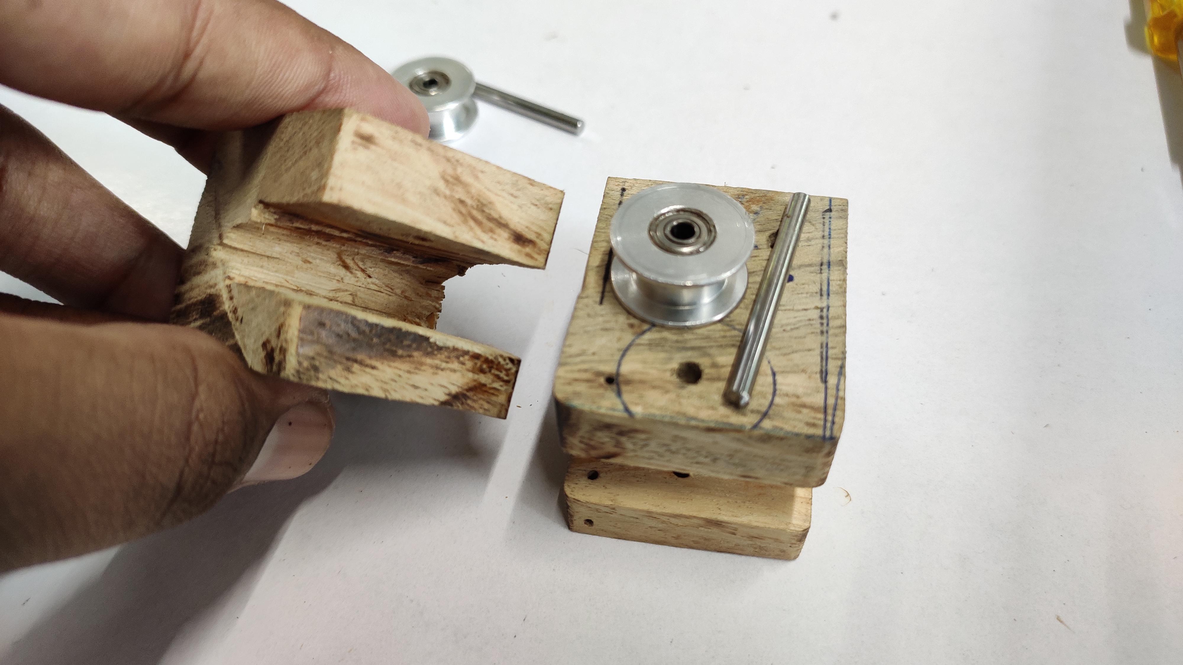
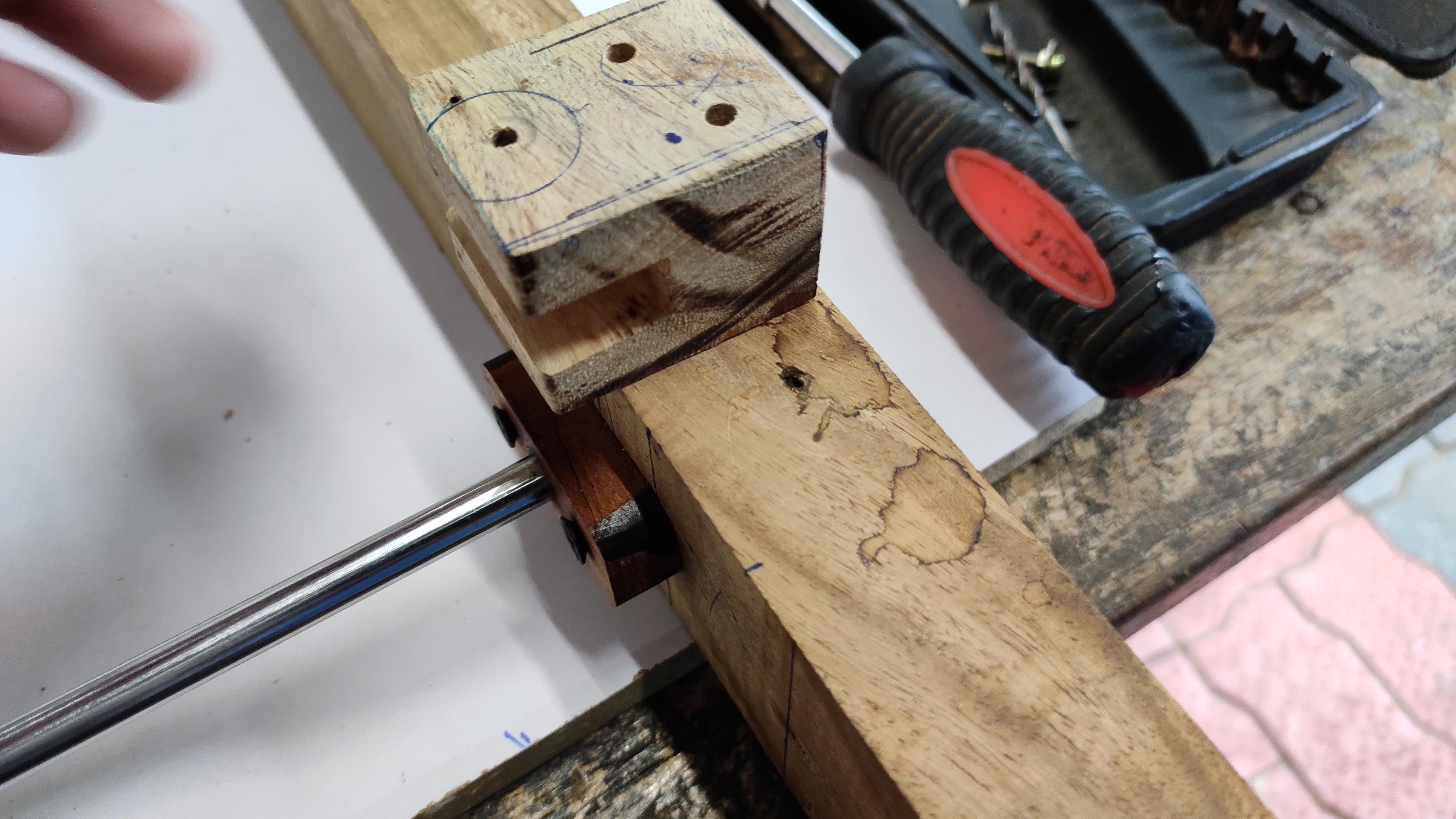
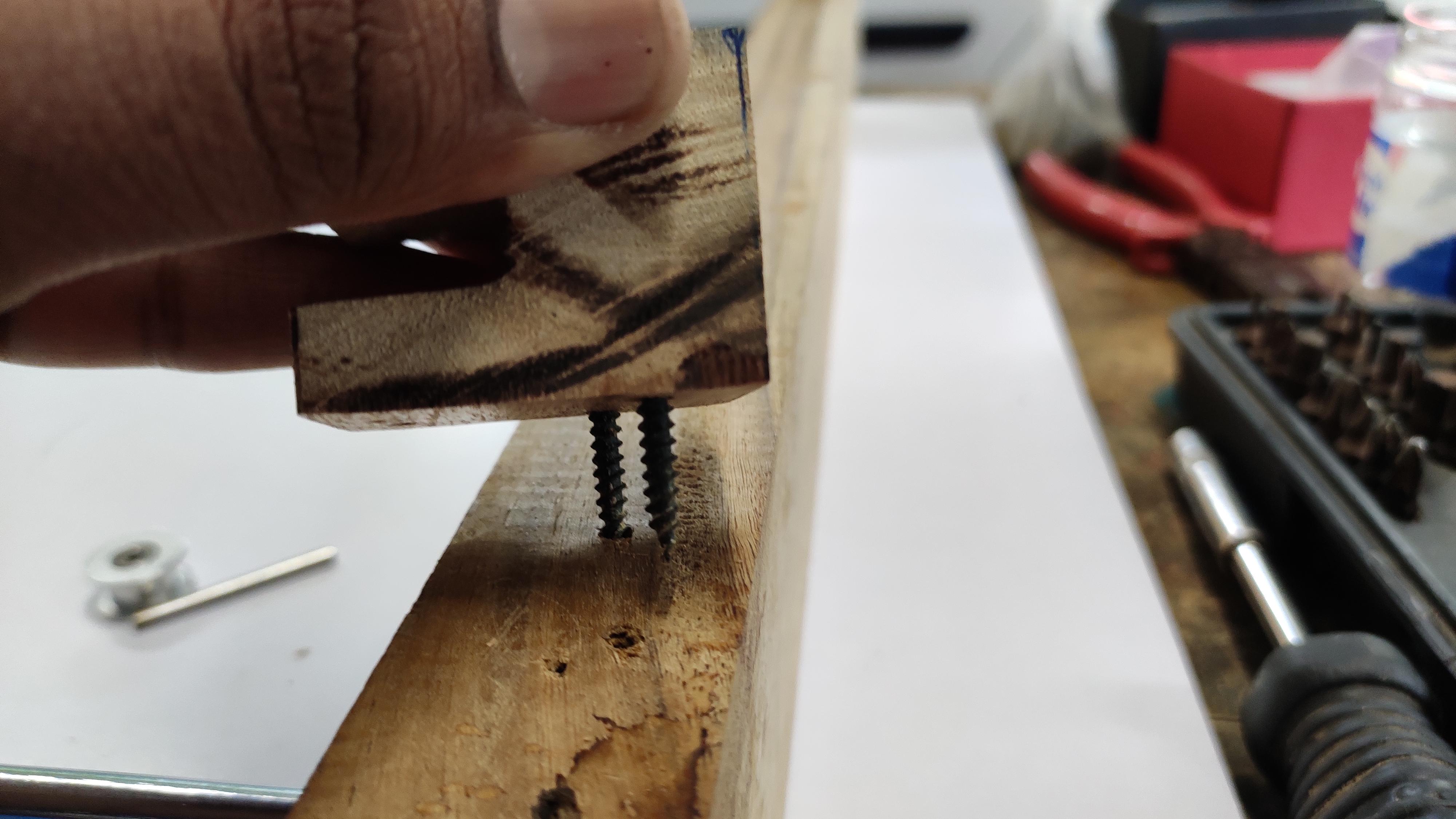
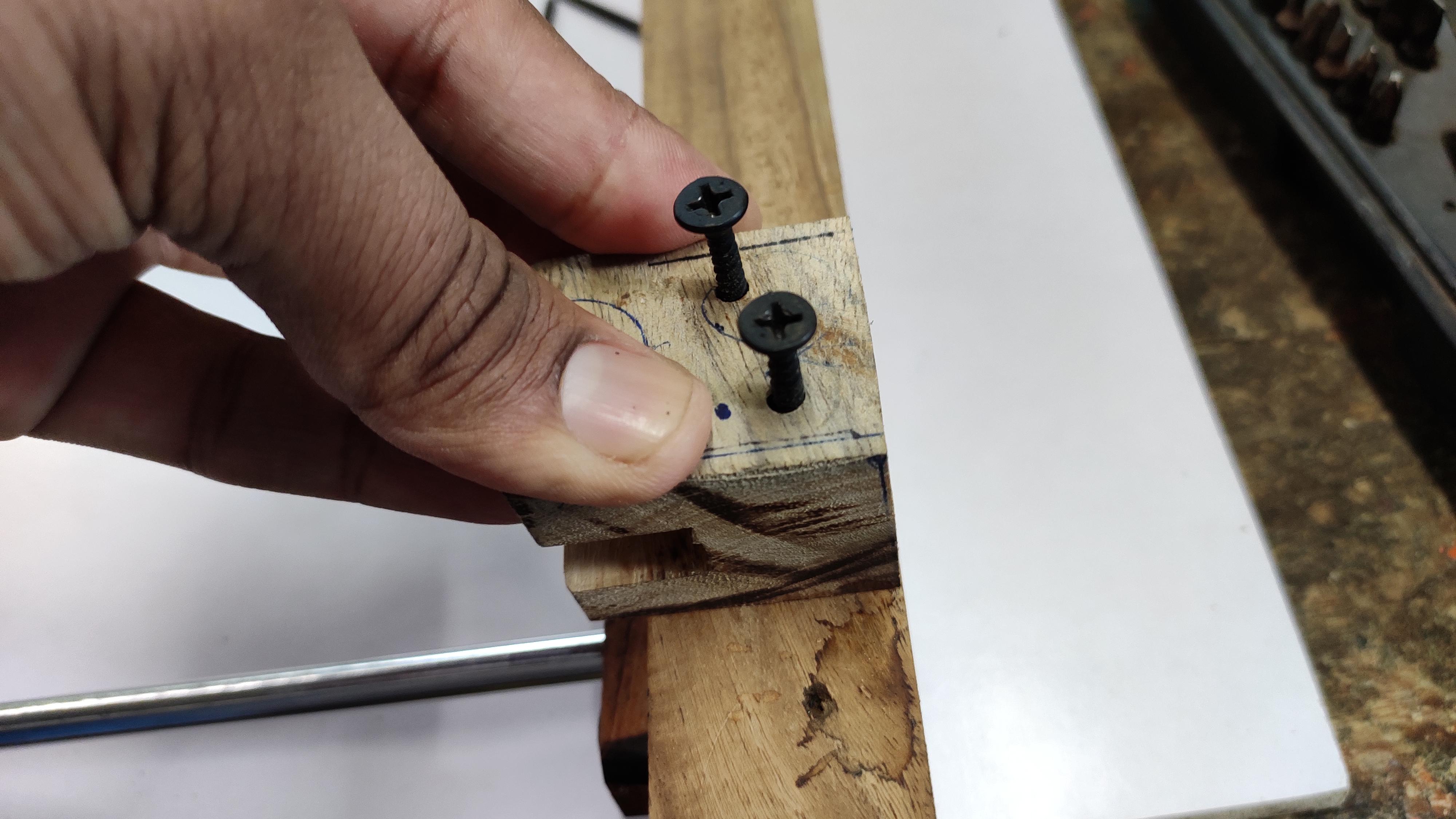
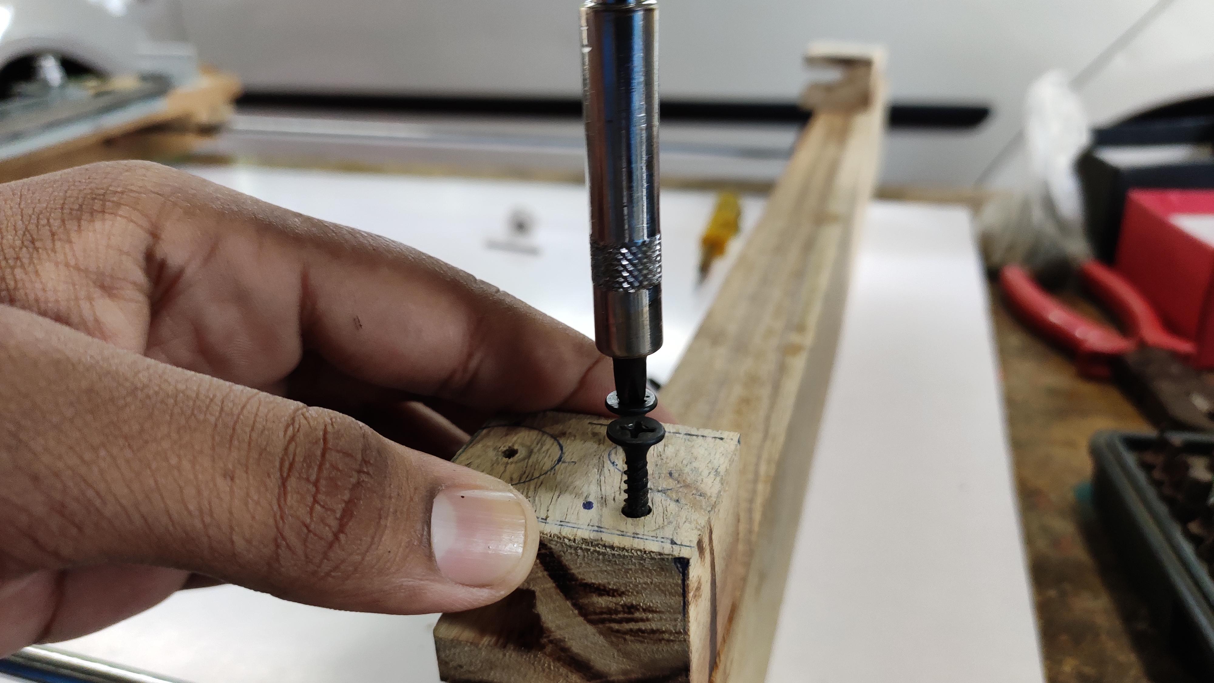
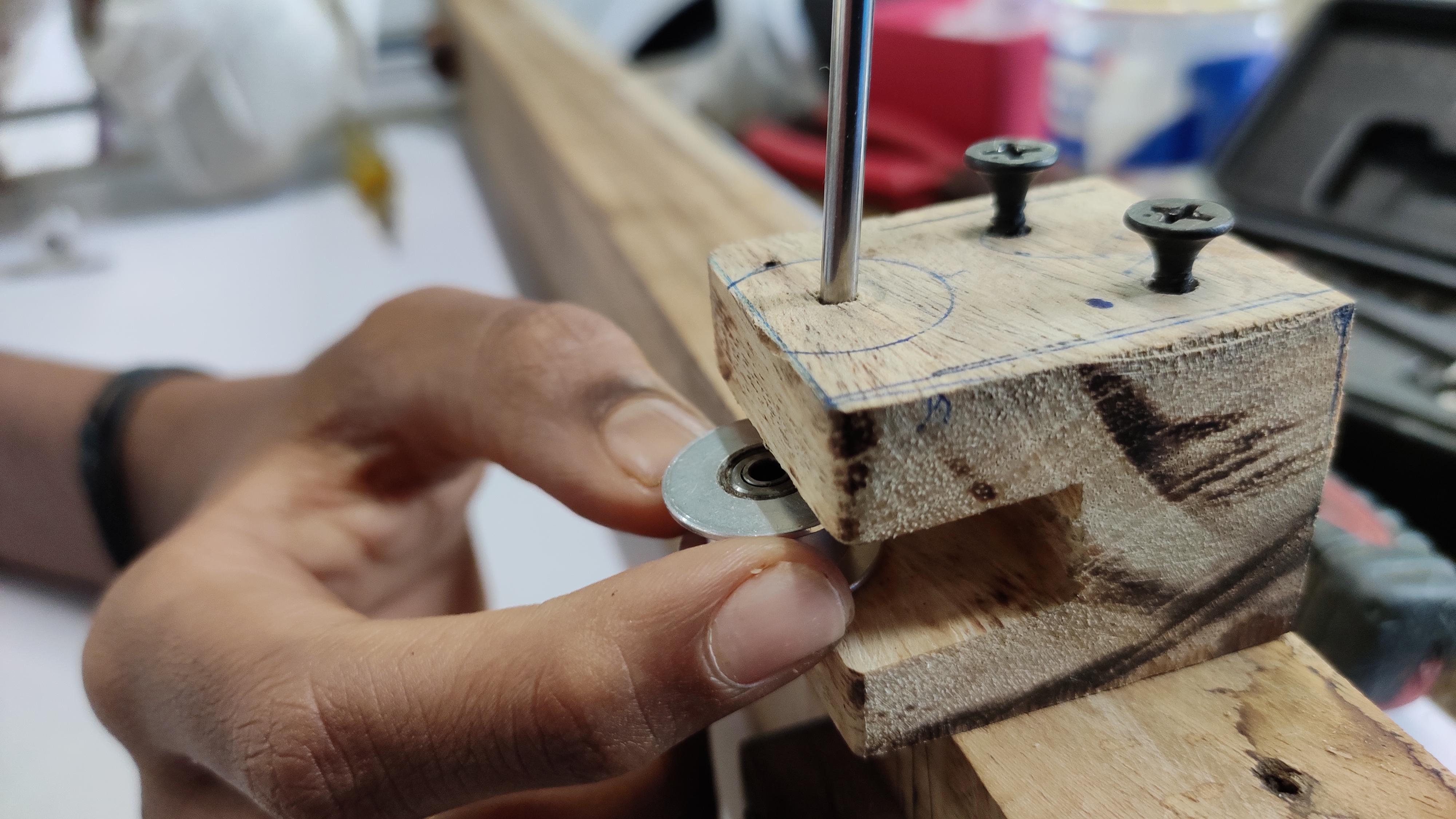
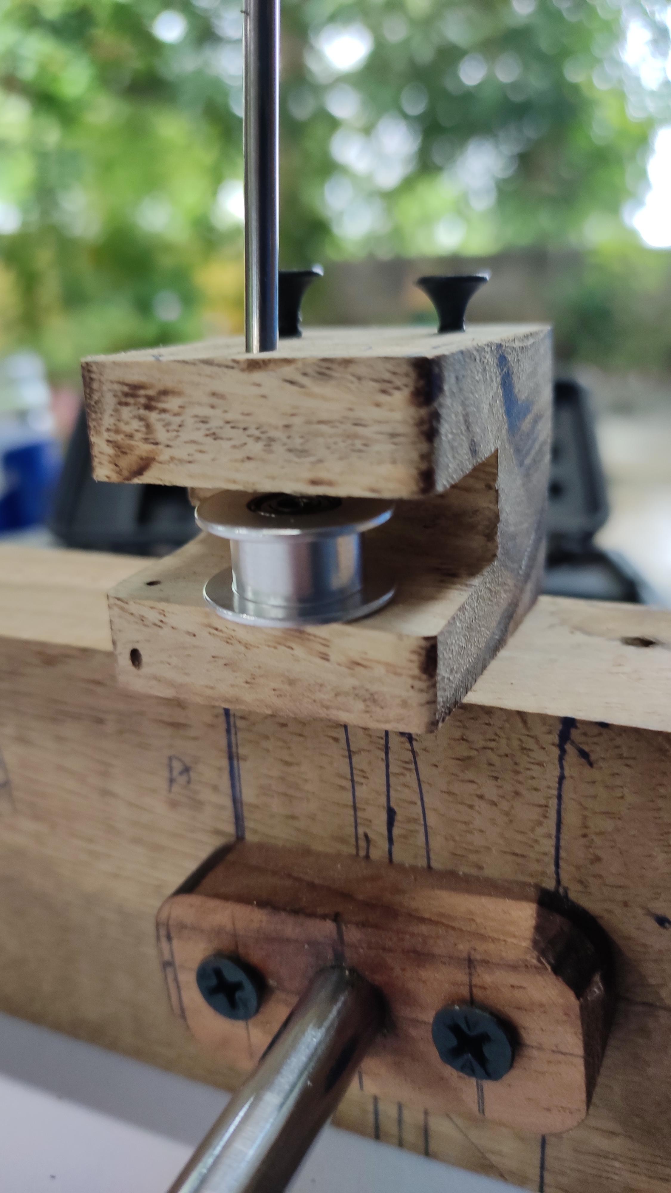
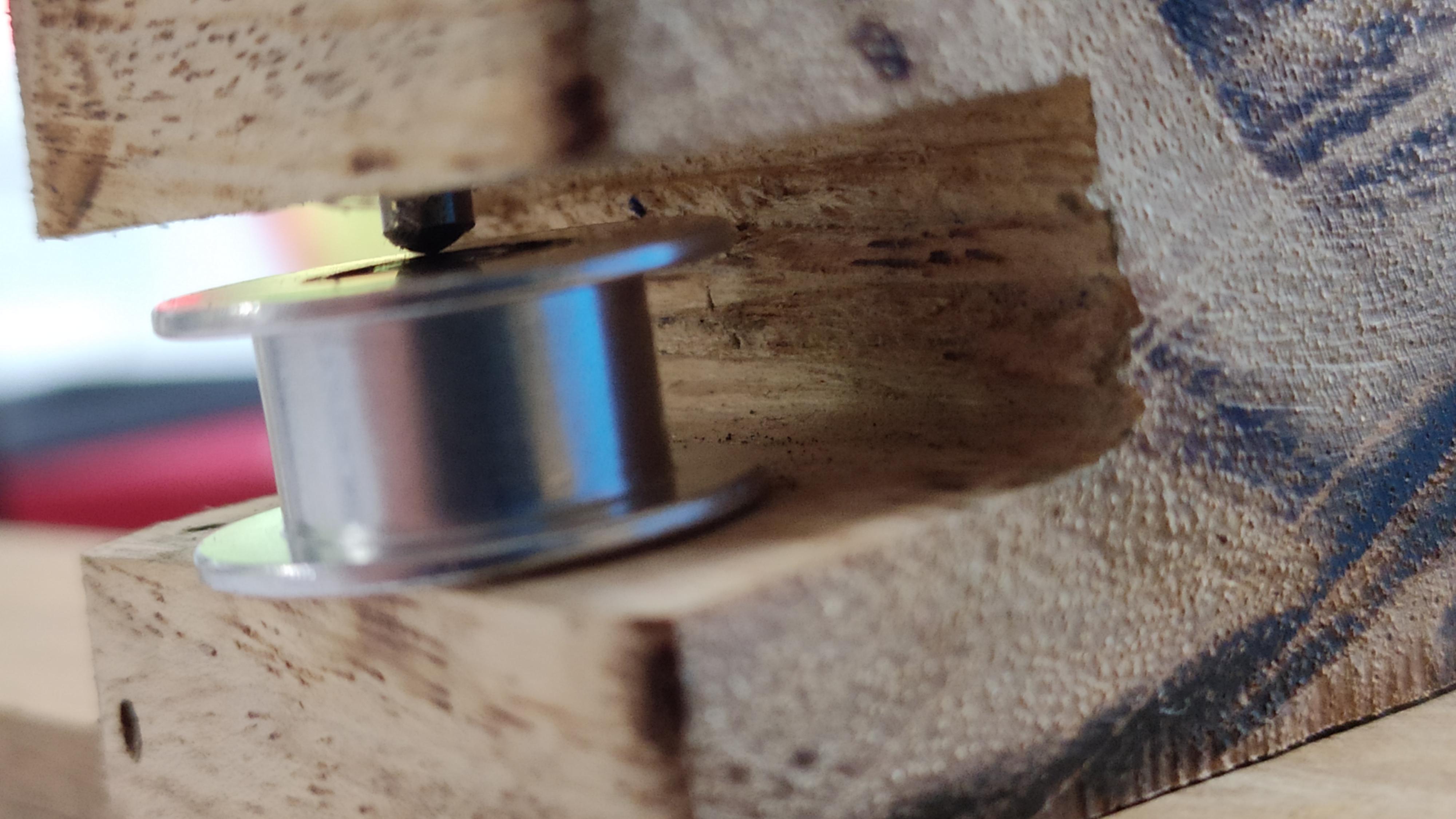
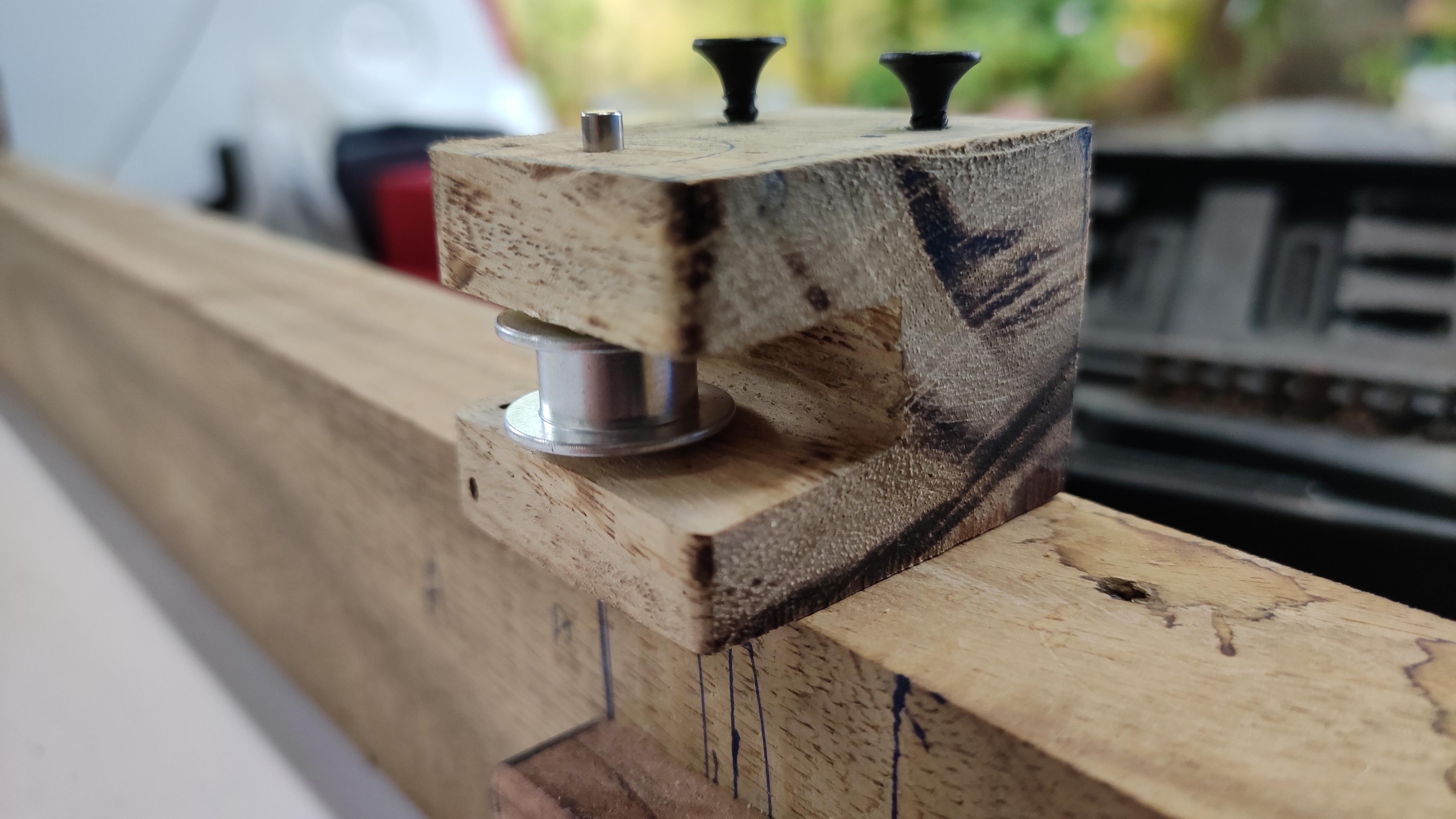
Want good result ? , then fix it more carefully, because if pulley is not in equal height then the timing belt may get loosen and starts wobble.
Take the two wooden pulley holder, GT-2 pulley and a small length smooth rod that fits through the pulley. The hole which acts as the axle for the pulley do not have more radius, better to have some tight while inserting...
After, screw it on the wooden block at the direct center of the motor,belt holder. The timing belt should pretty straight enough. follow the steps as shown in the above pictures.
Z-Axis (pen Up/down Mechanism) :)
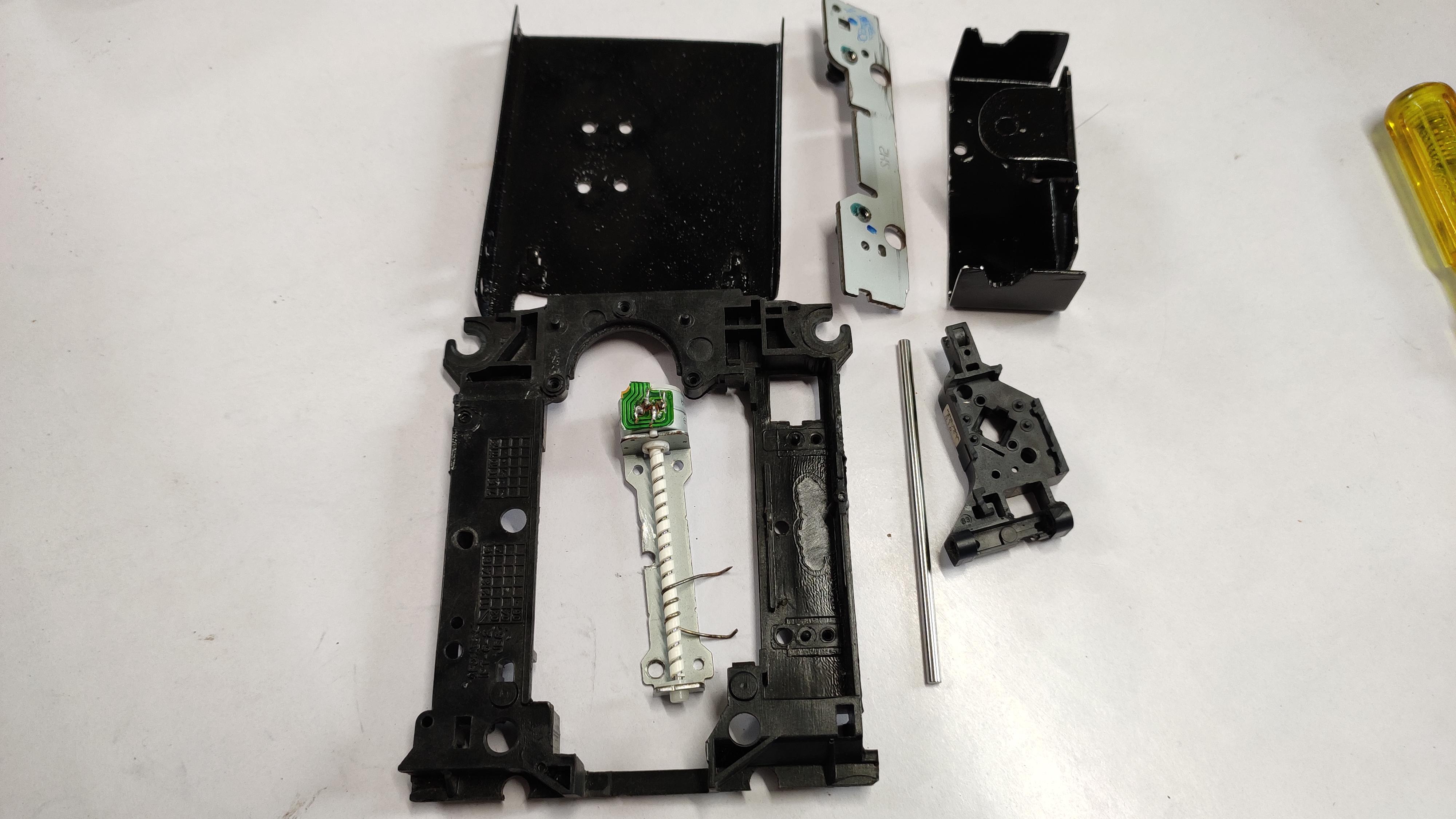
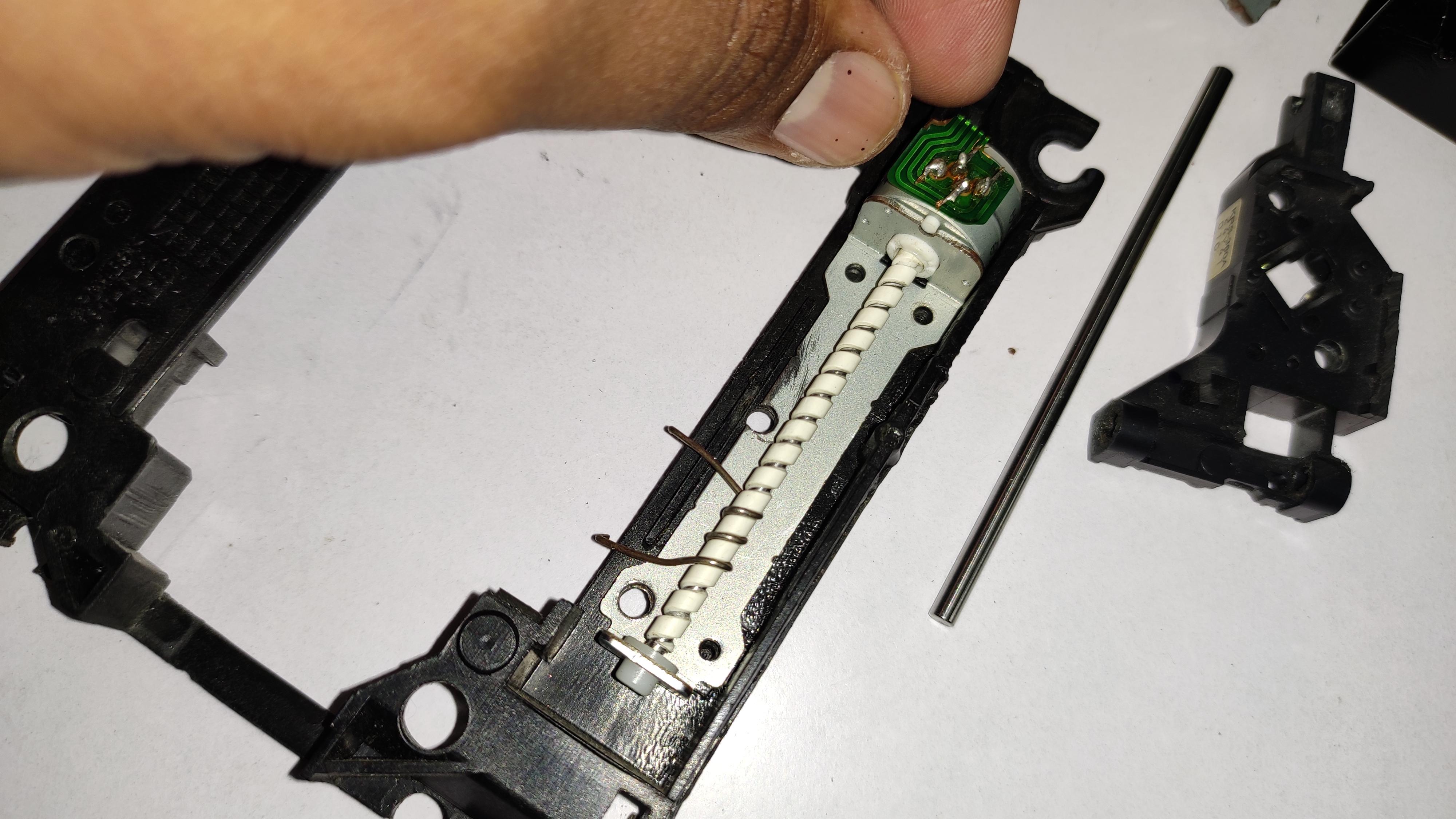
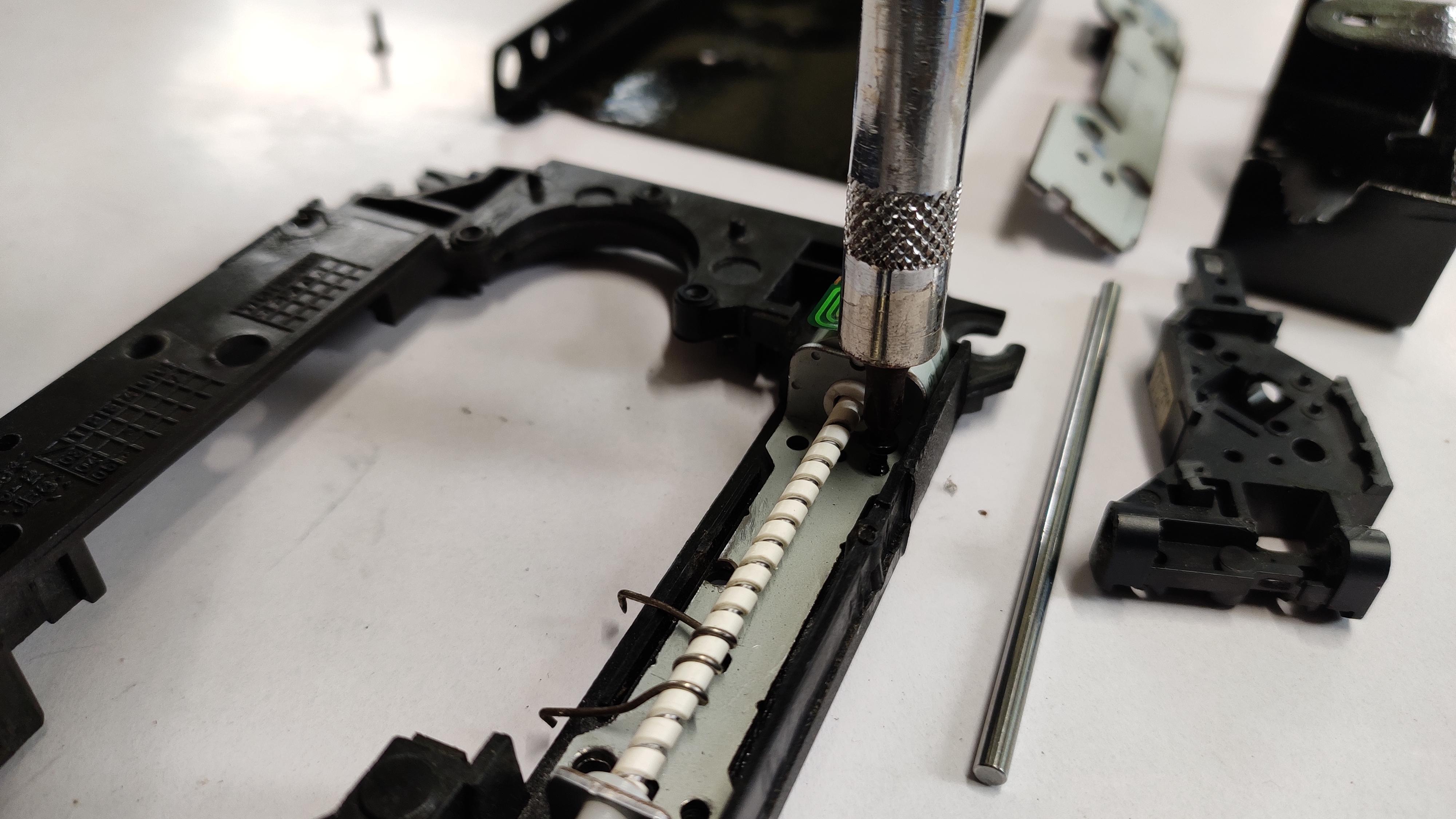
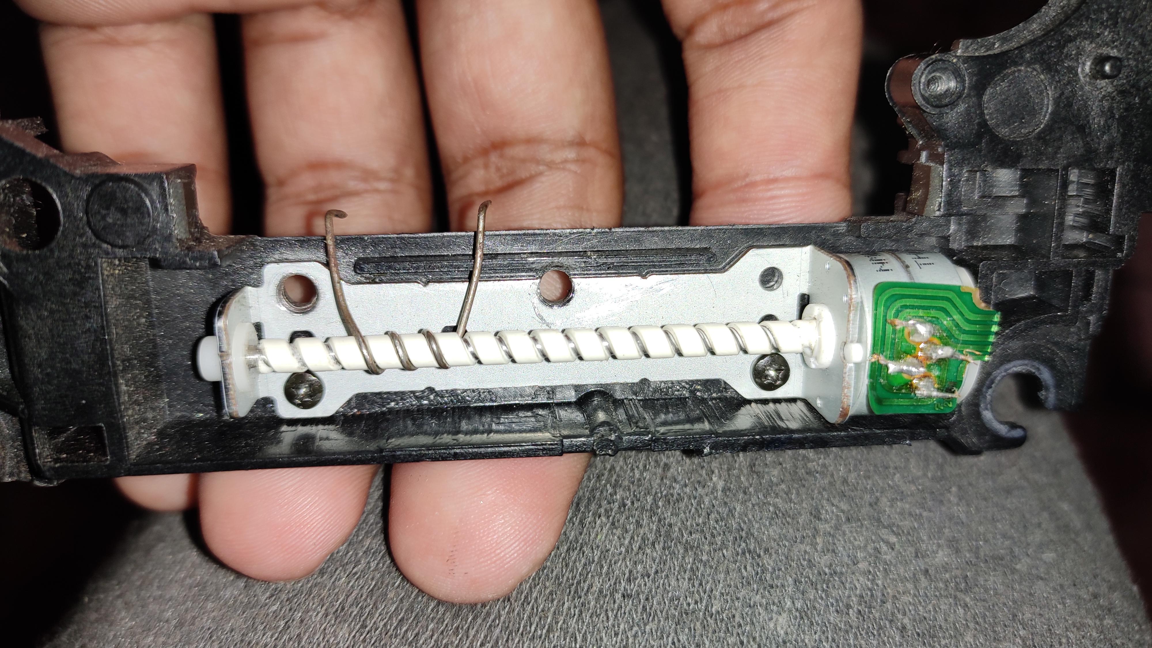
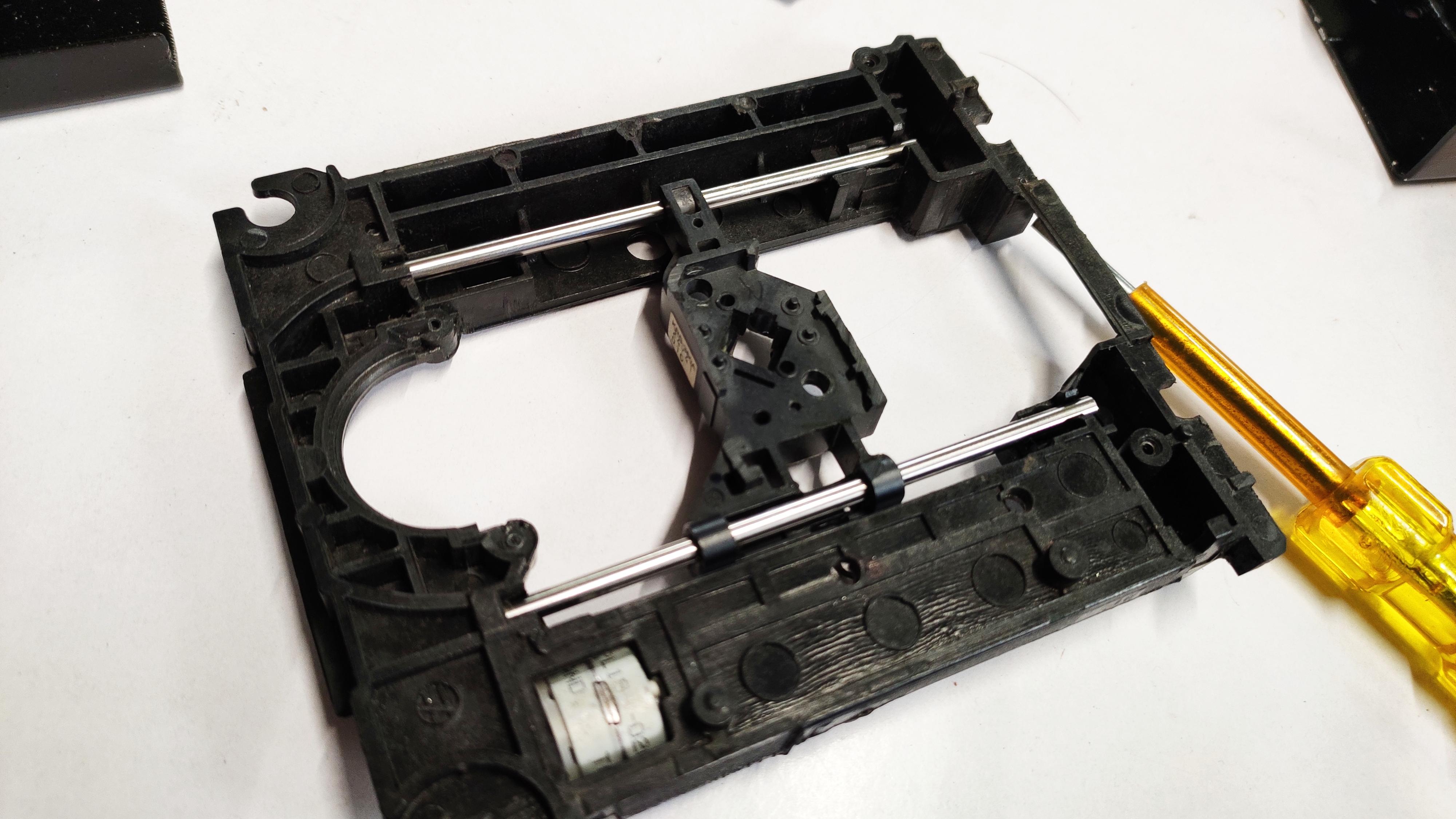
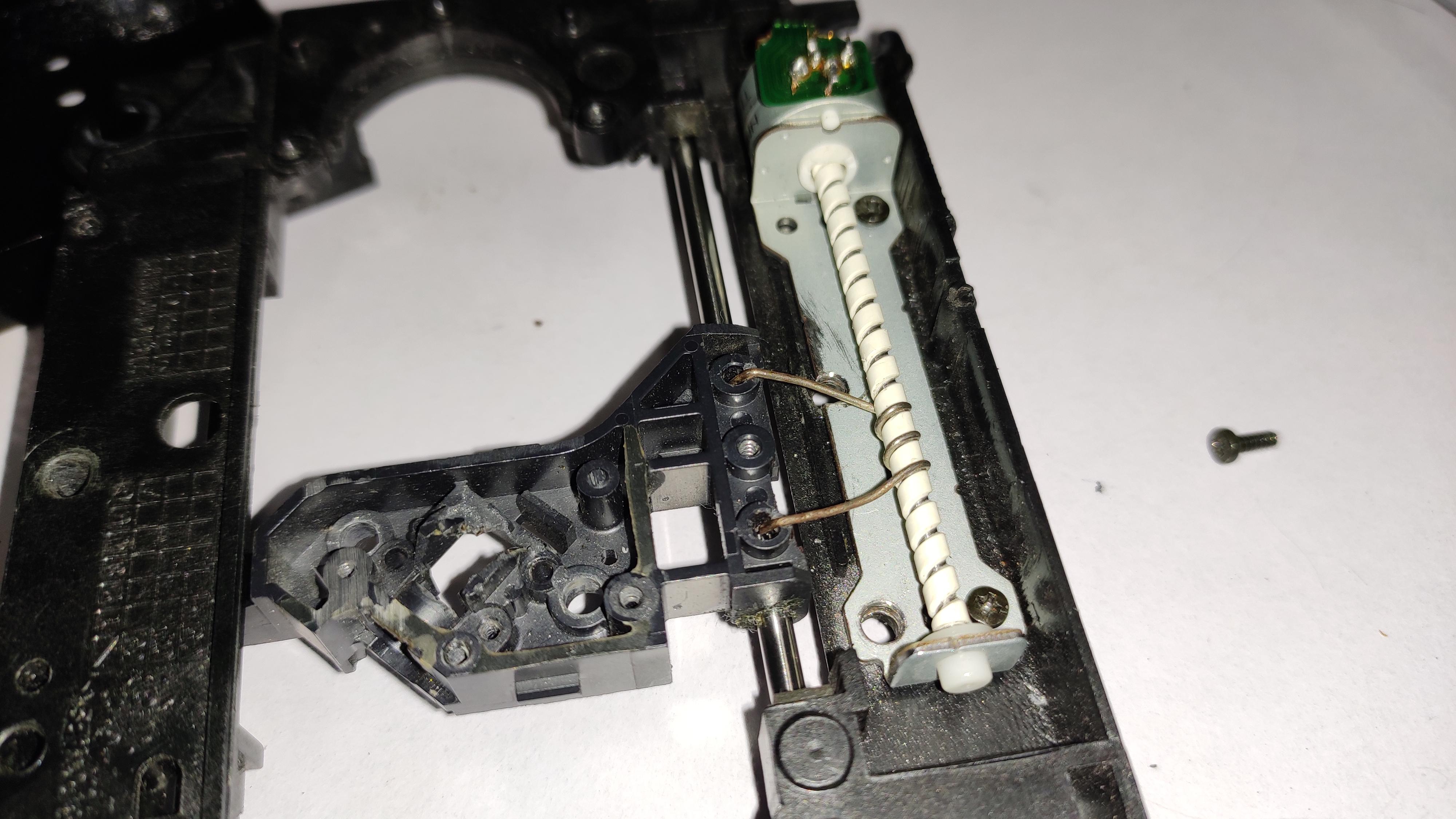
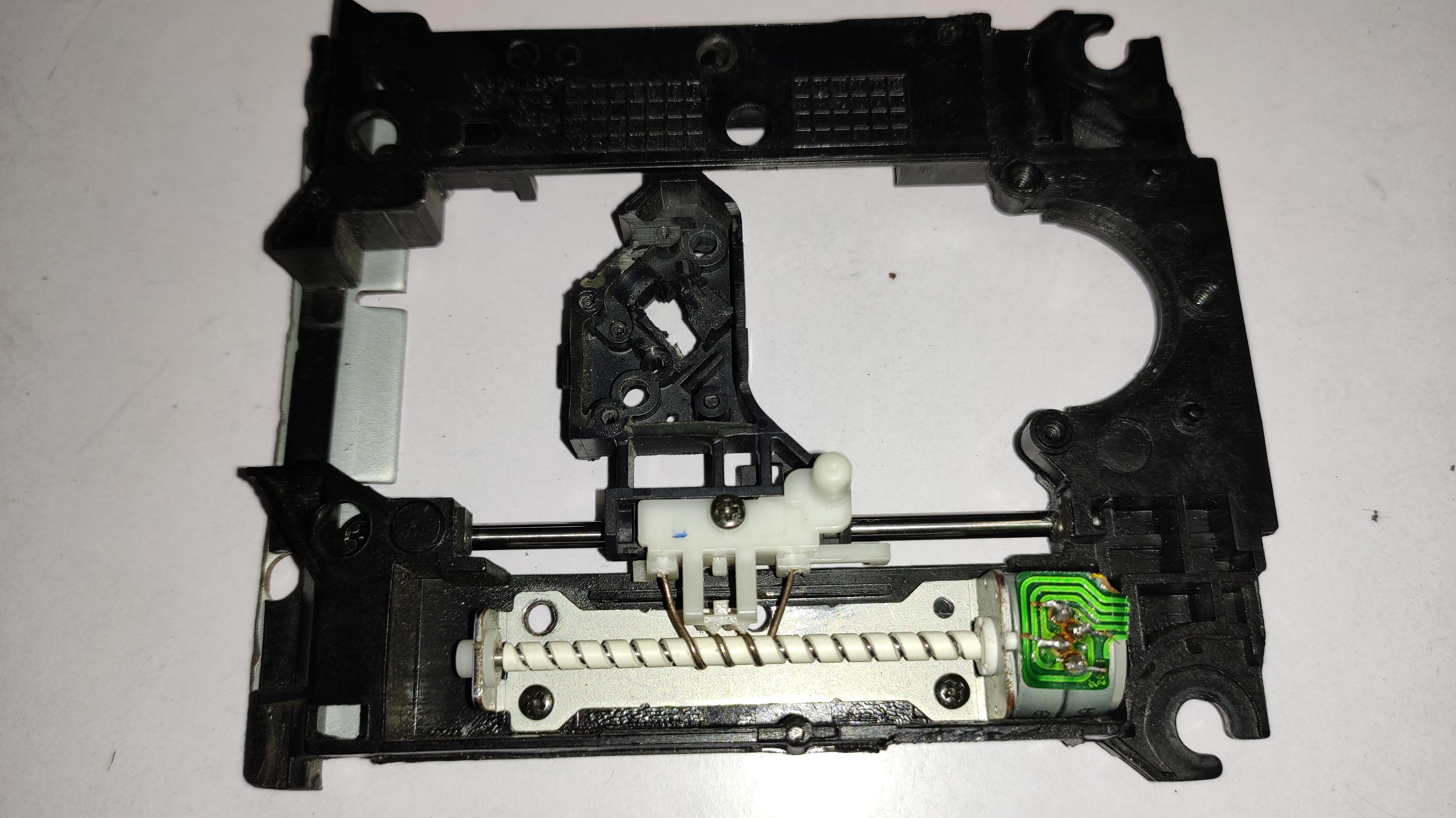
We had covered almost all the parts of structural built section.
Placing the DVD small stepper motor on that frame, screw it. you can find those things inside your old home DVD/ computer DVD Disk, carefully take these out from it.
In this part i had found a bit problem with those slider which is attached to the slider (that white thing)
So we need something strong for the up-down movement, take a safety pin and bend it as shown in the picture, apply some force to bend, attach it to slider(the black platform) through that white holder and screw it, don't over tighten it, may have chance to break.Ensure that the motor is screwed properly..
This is part were we attach the pen. And this acts as the Z-Axis for the machine. Because of the steppers are too small they may have chance to overheat, so i recommend you to fit some heat sink behind the motor, so this helps the motor to cooooool.
Adding Pen Holder - Attaching All to X-axis Frame
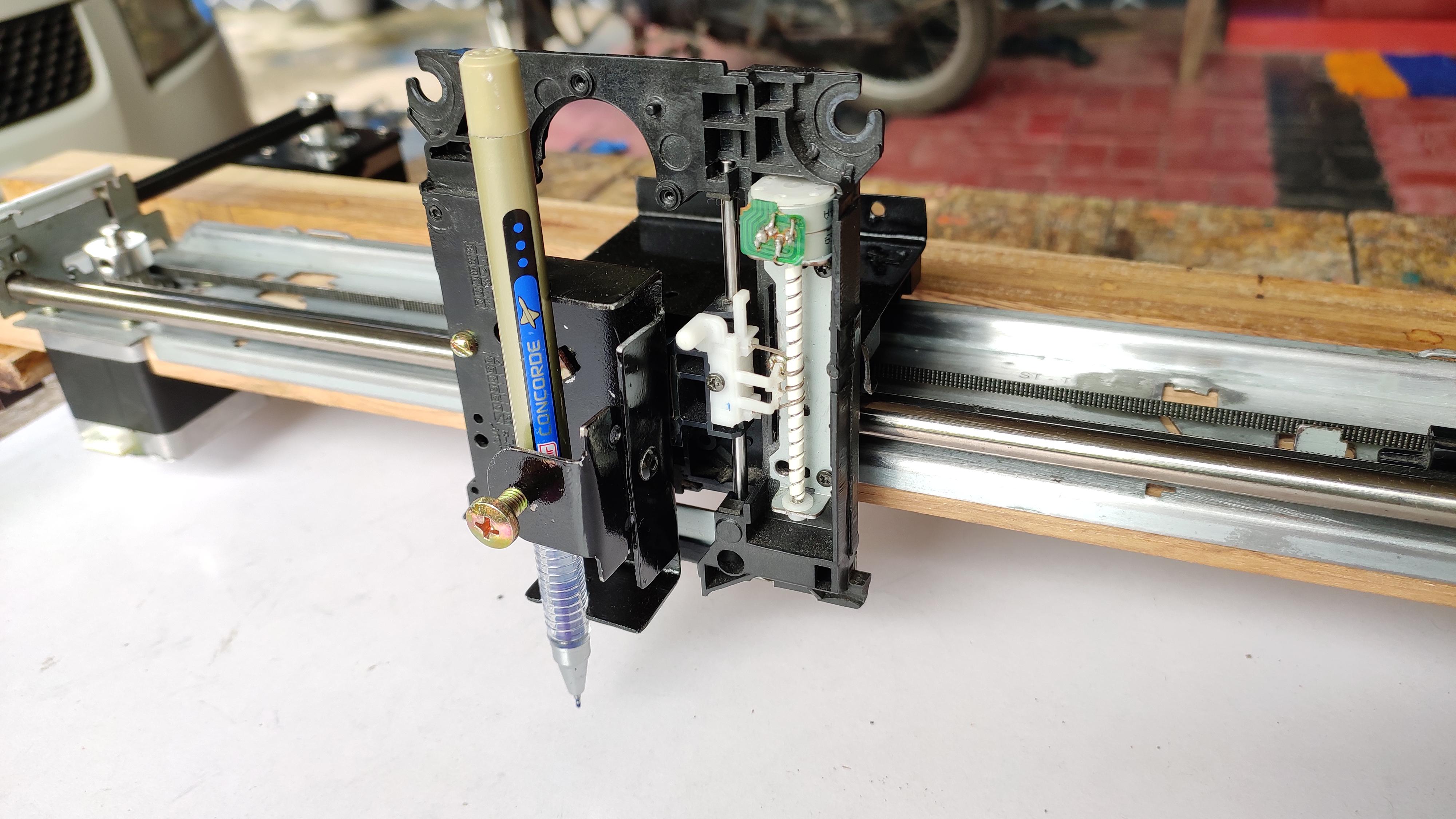
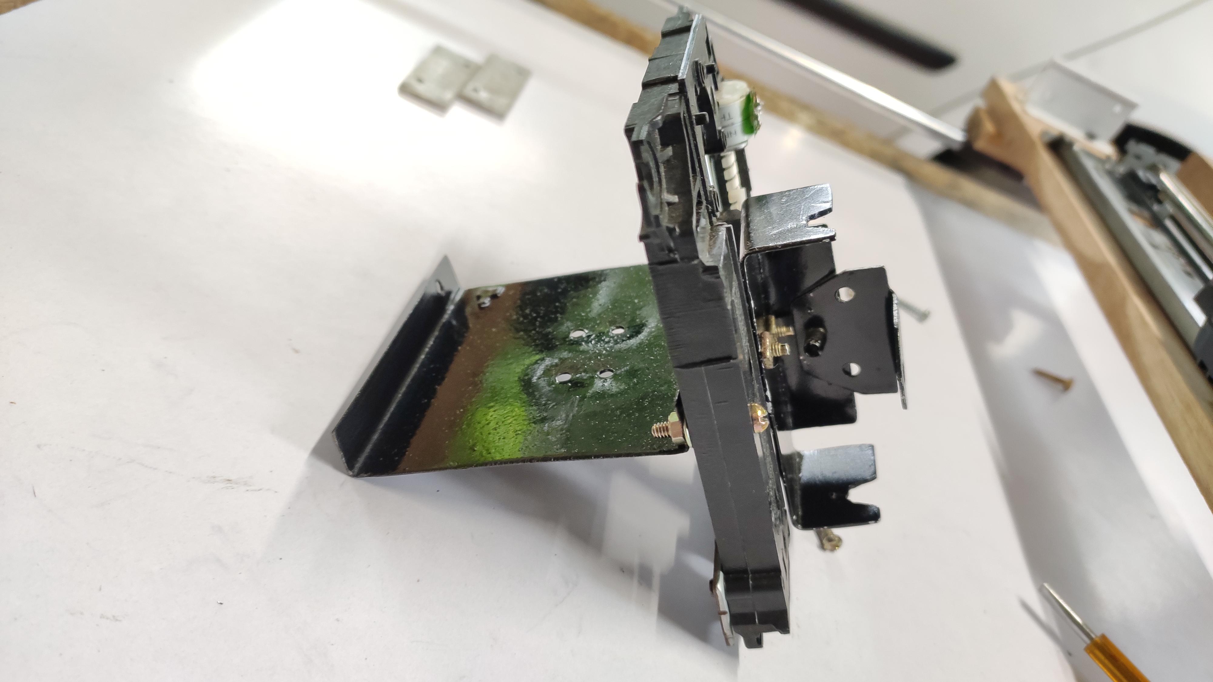
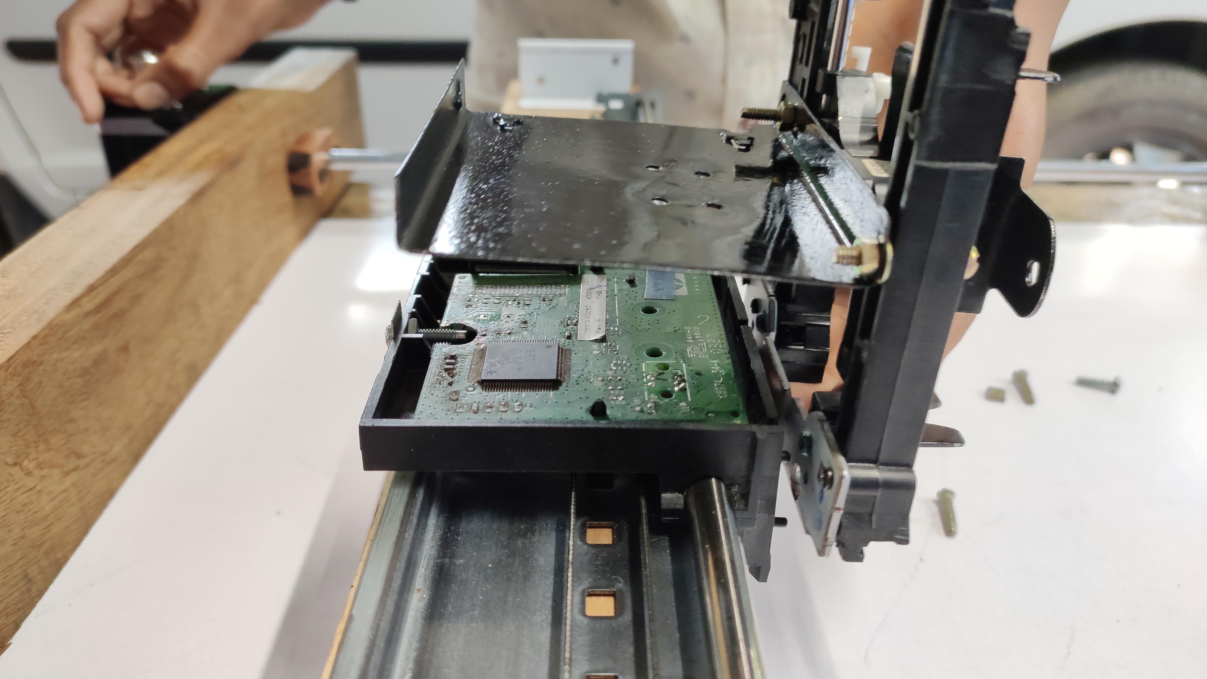
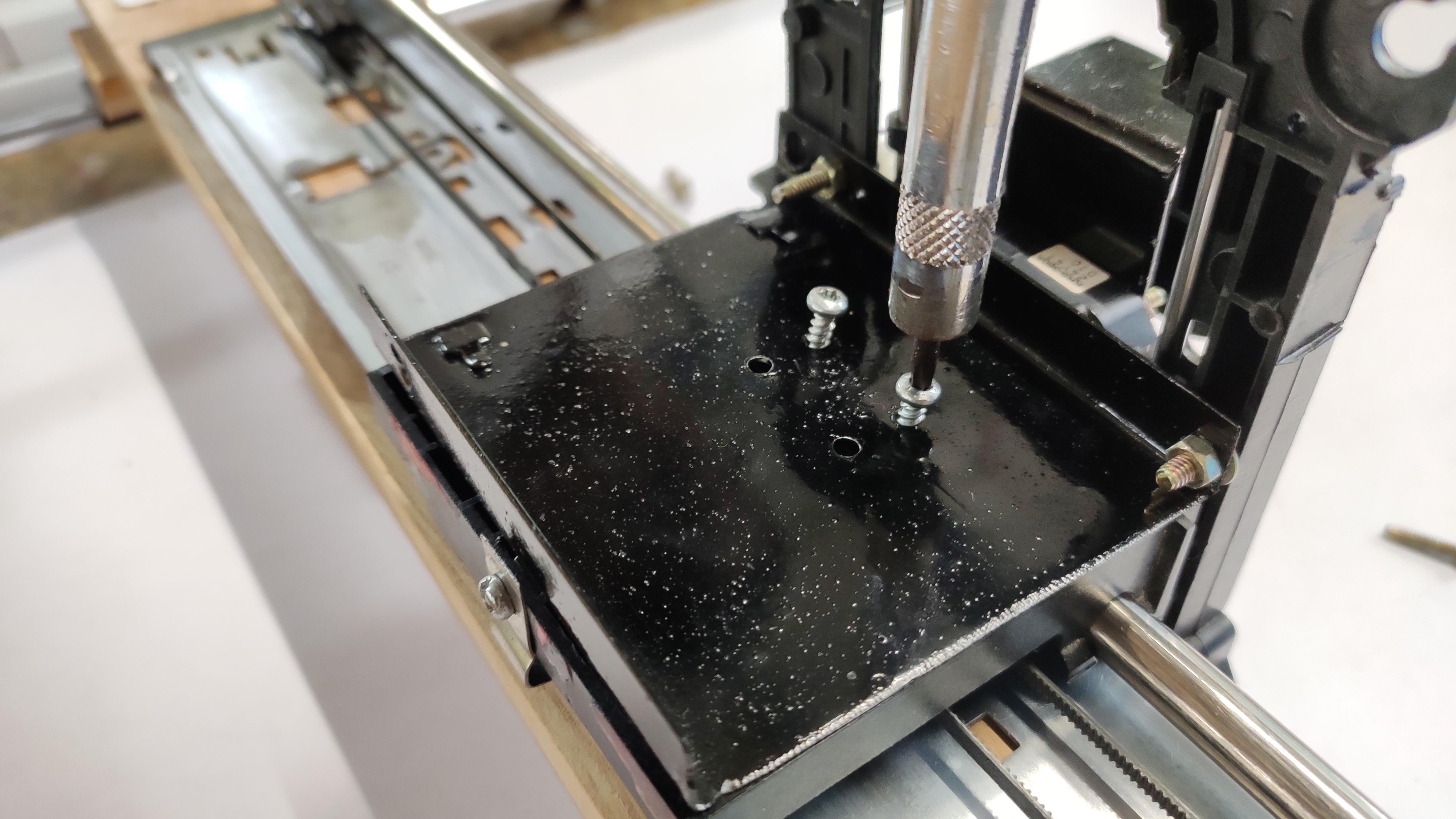
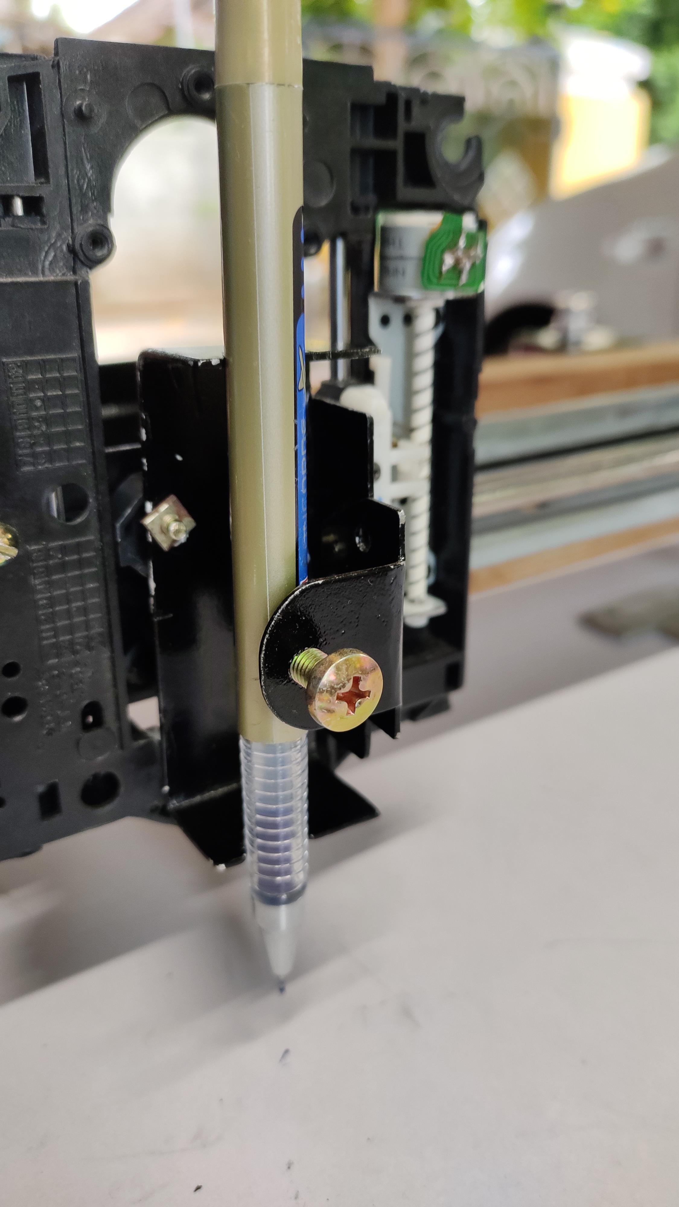
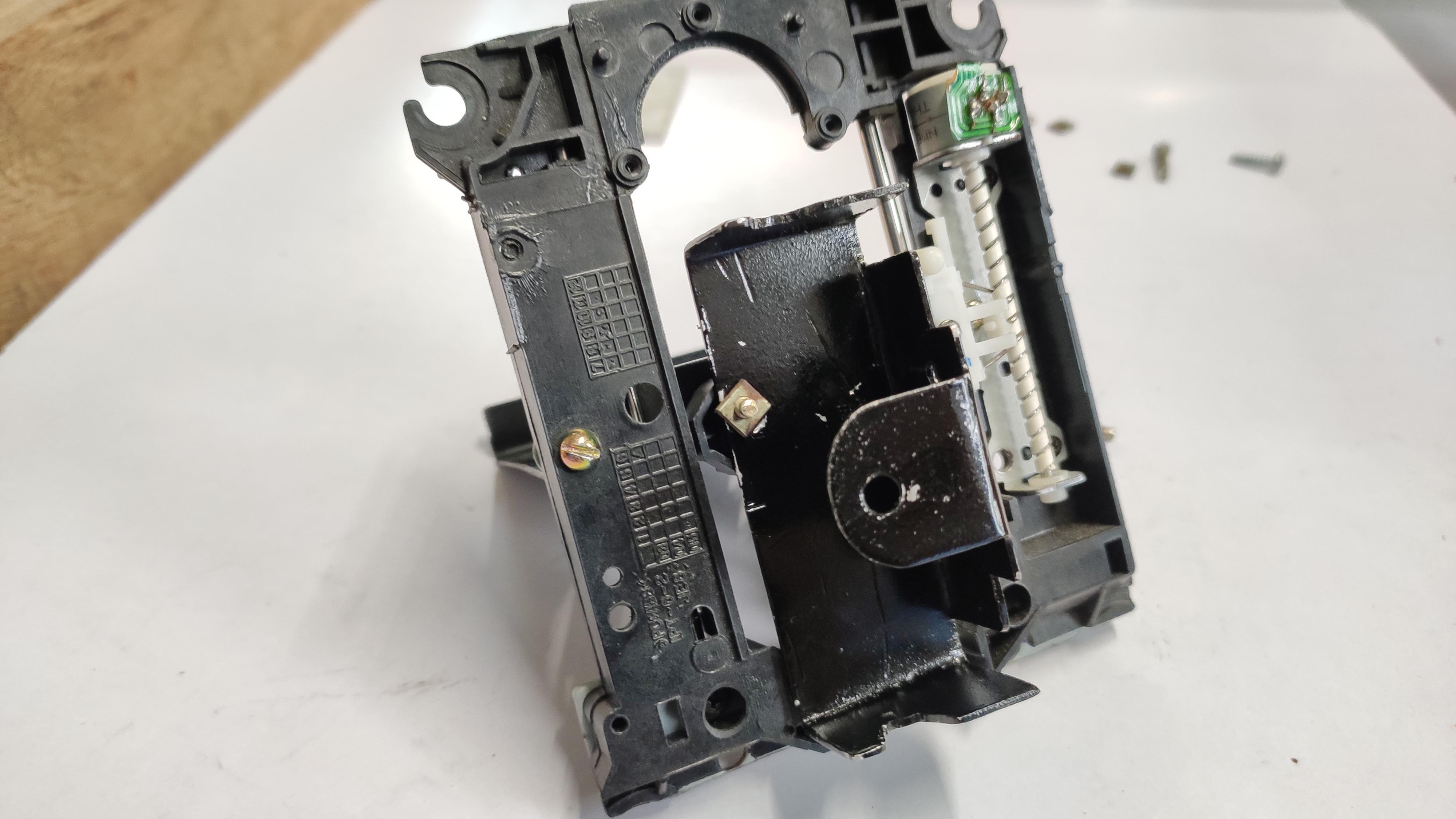
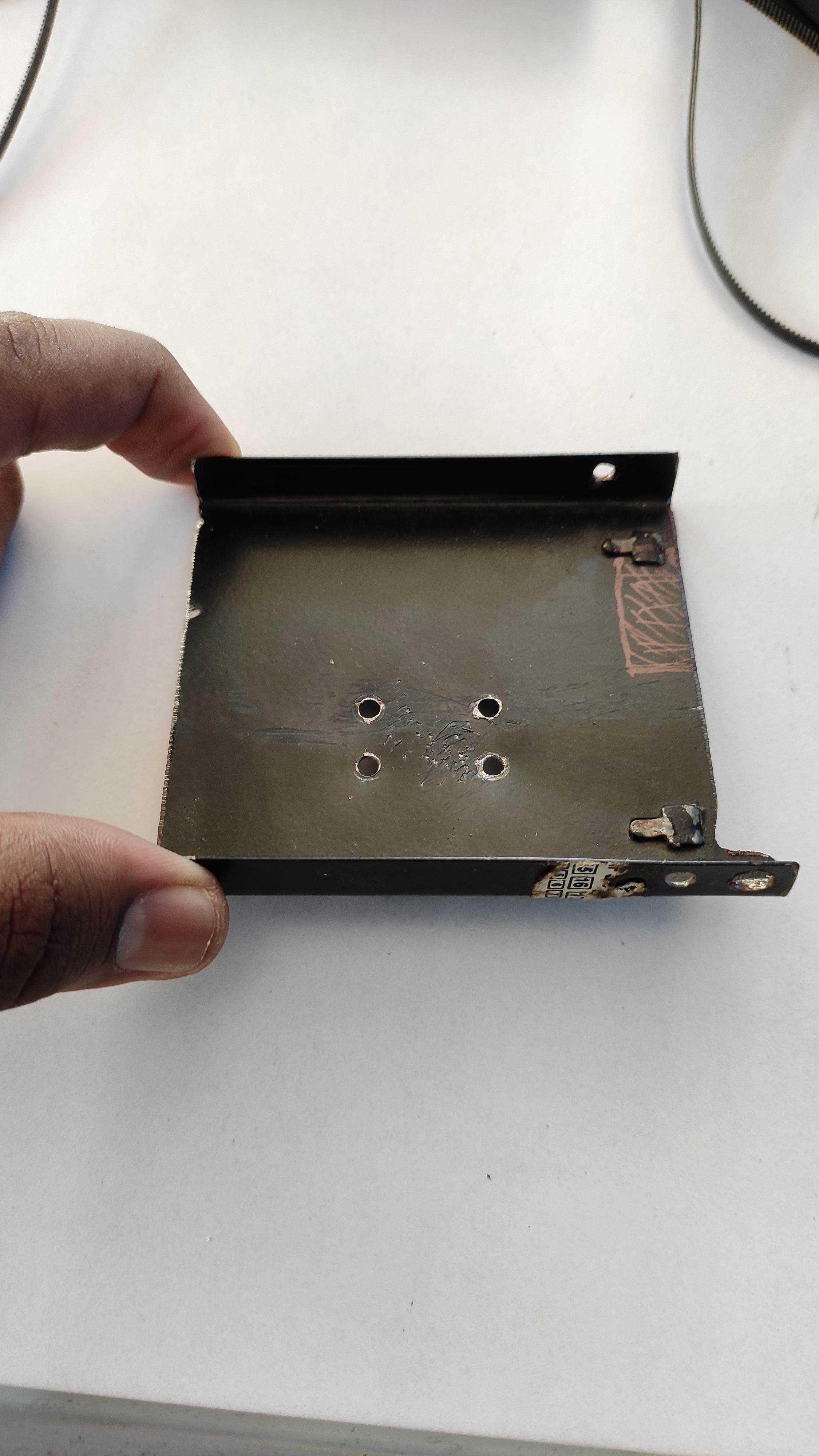
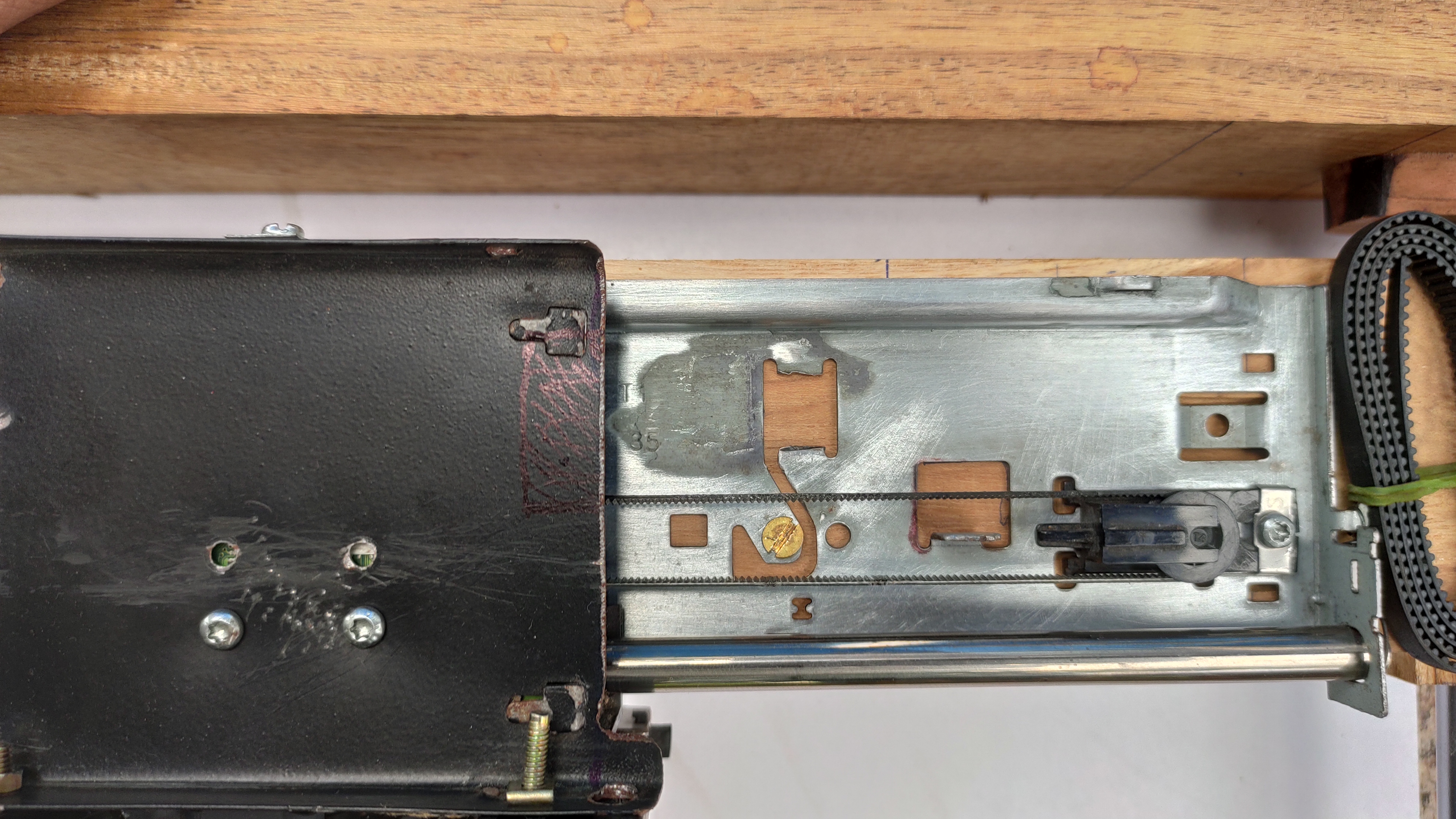
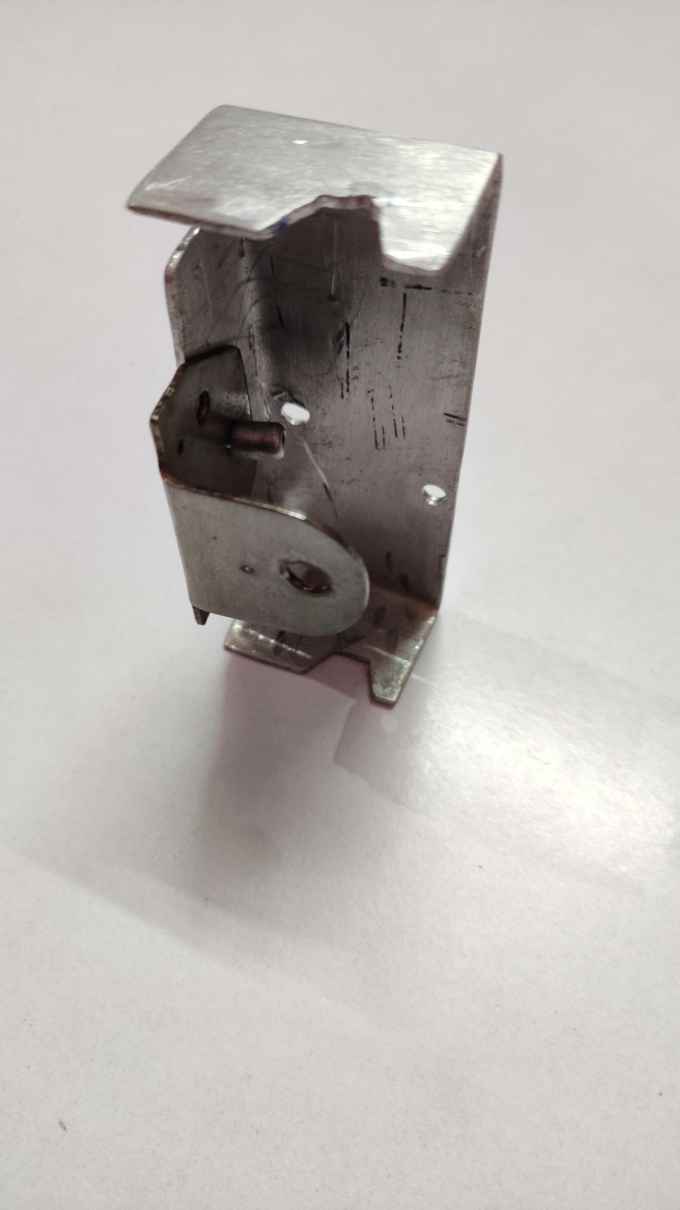
Here we are taking the same part which we deal in the previous section.
Now we are going to attach a pen holder on the slider. I had made long 'u' shaped aluminium bracket, has designed for a perfect fit to the pen, markers etc..
Take the holder, using nut,bolts attach it with the black lens slider. After that attach the aluminium stand to the Z-Axis frame, which helps to fit the Z-axis frame and X-axis slider together,do not forget it to screwed. After these steps test the slider by moving in opposite directions.
Attaching Timing Belts:
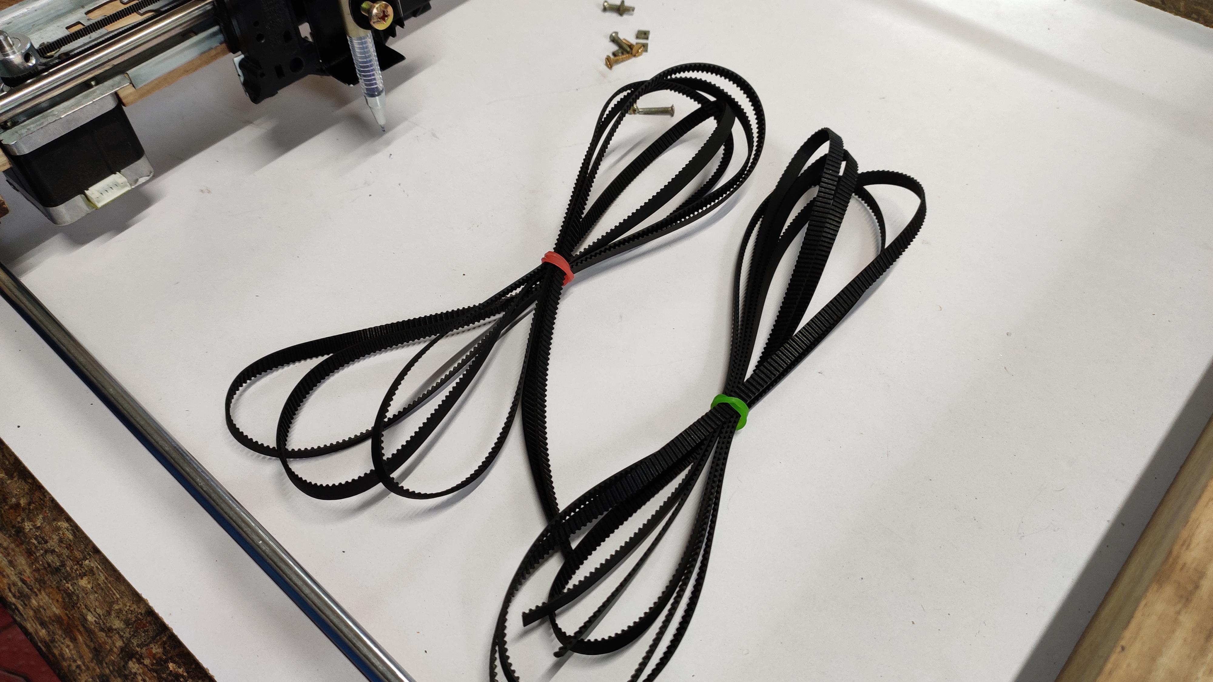
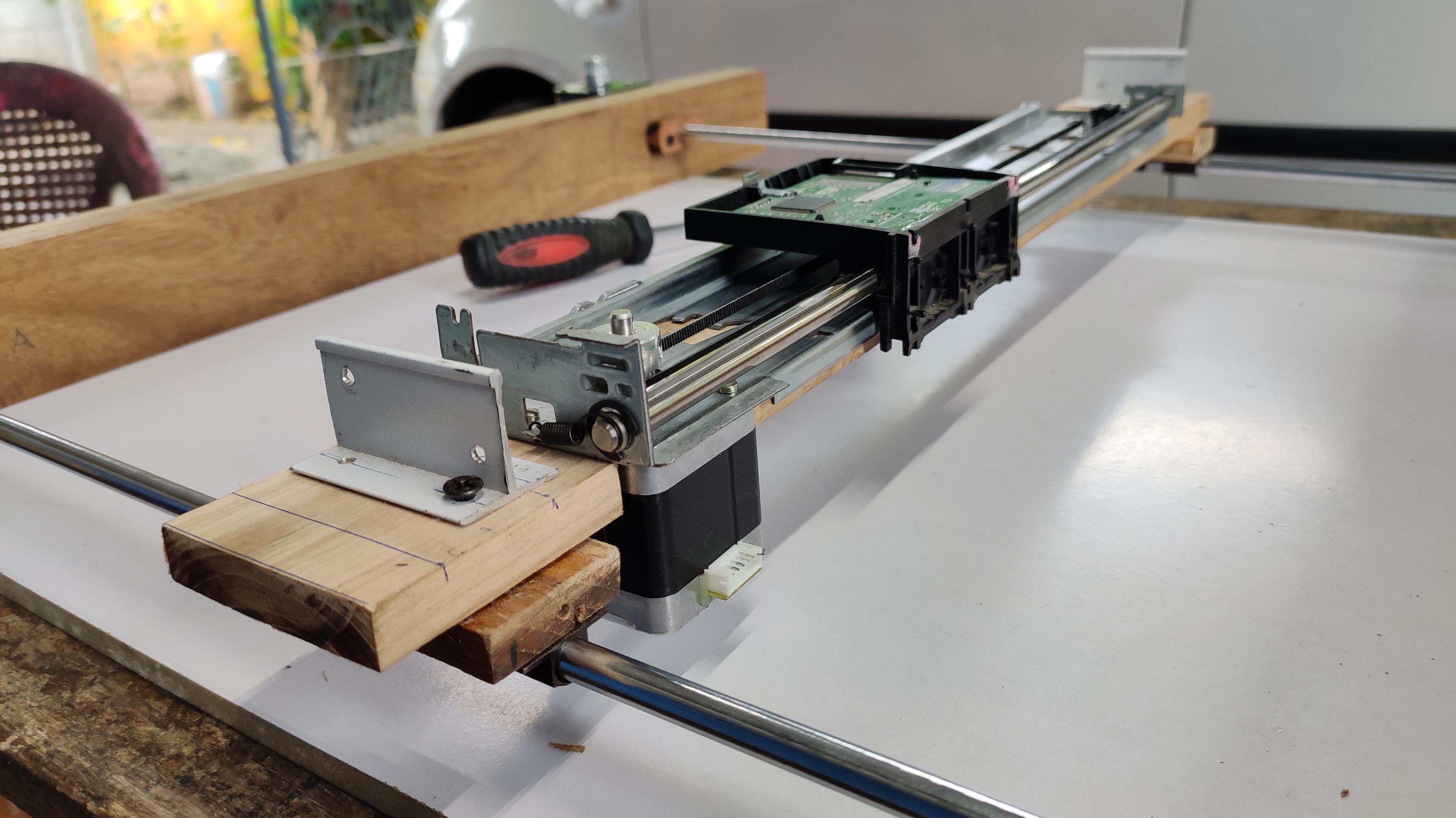
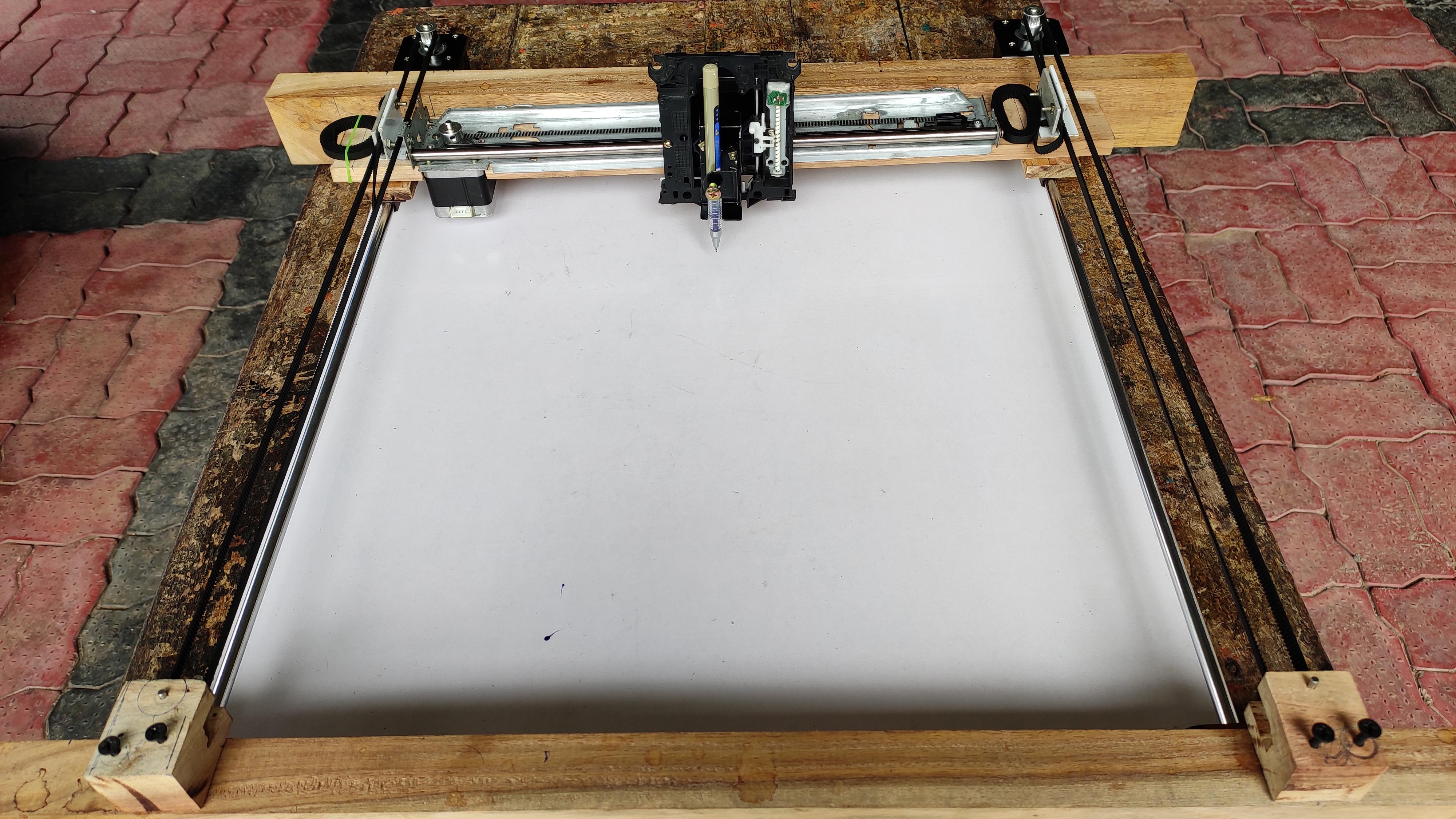
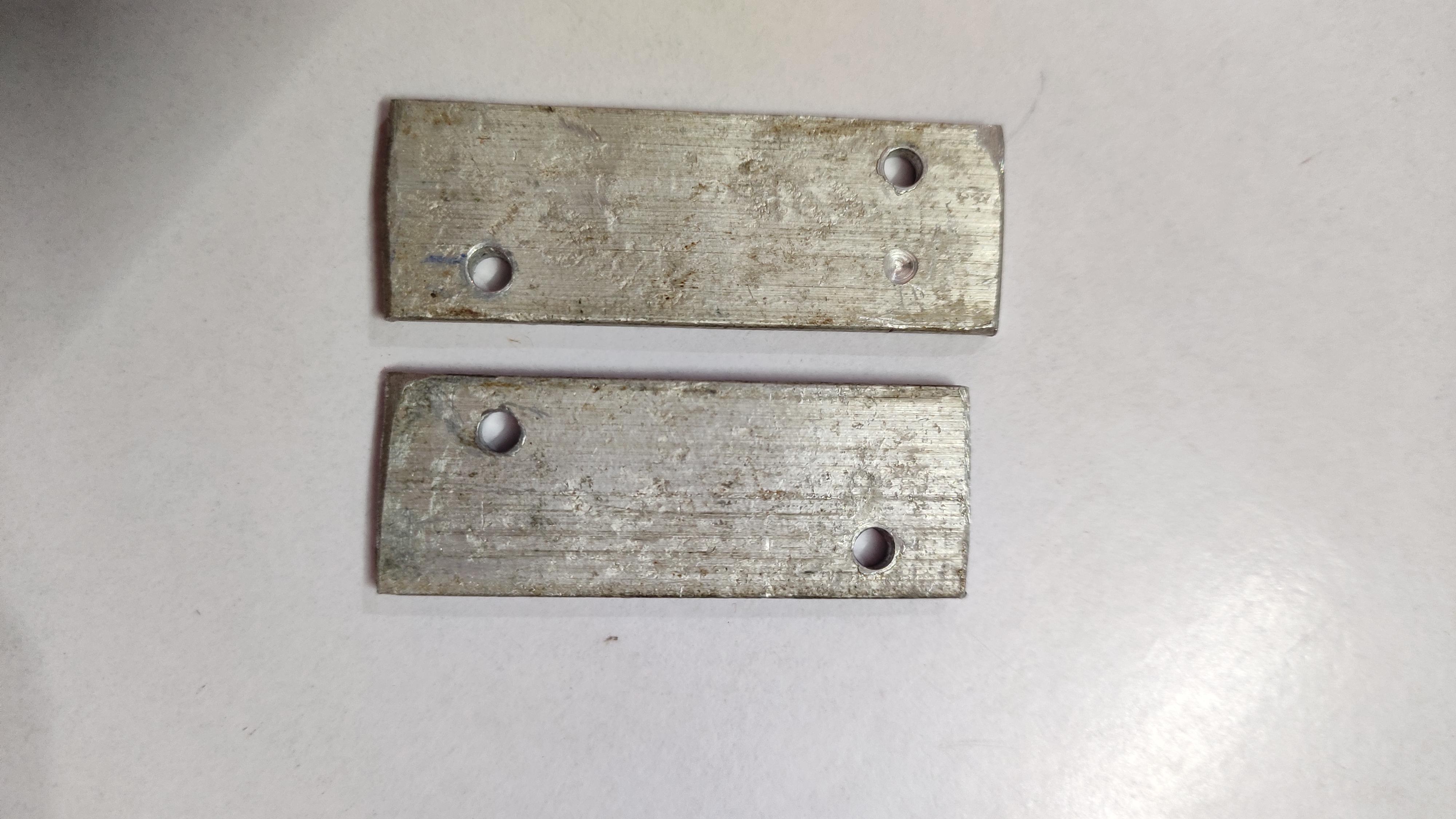
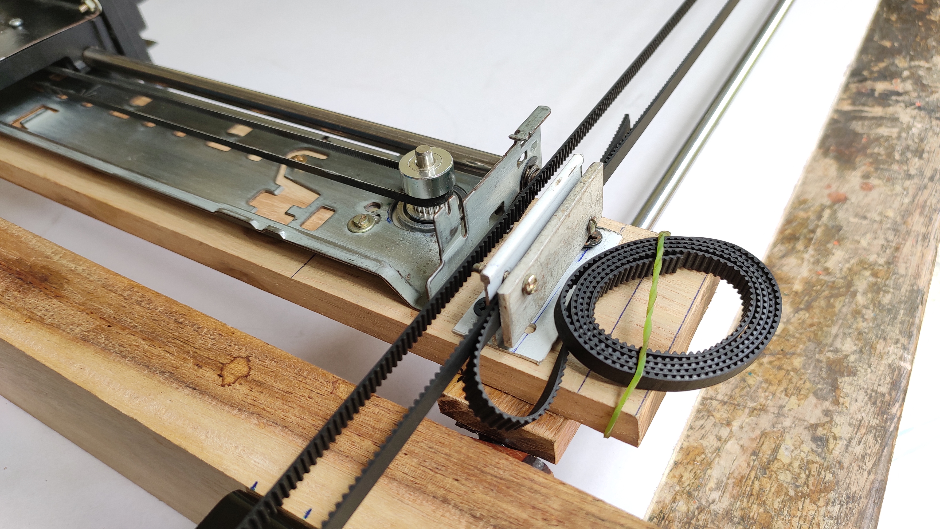
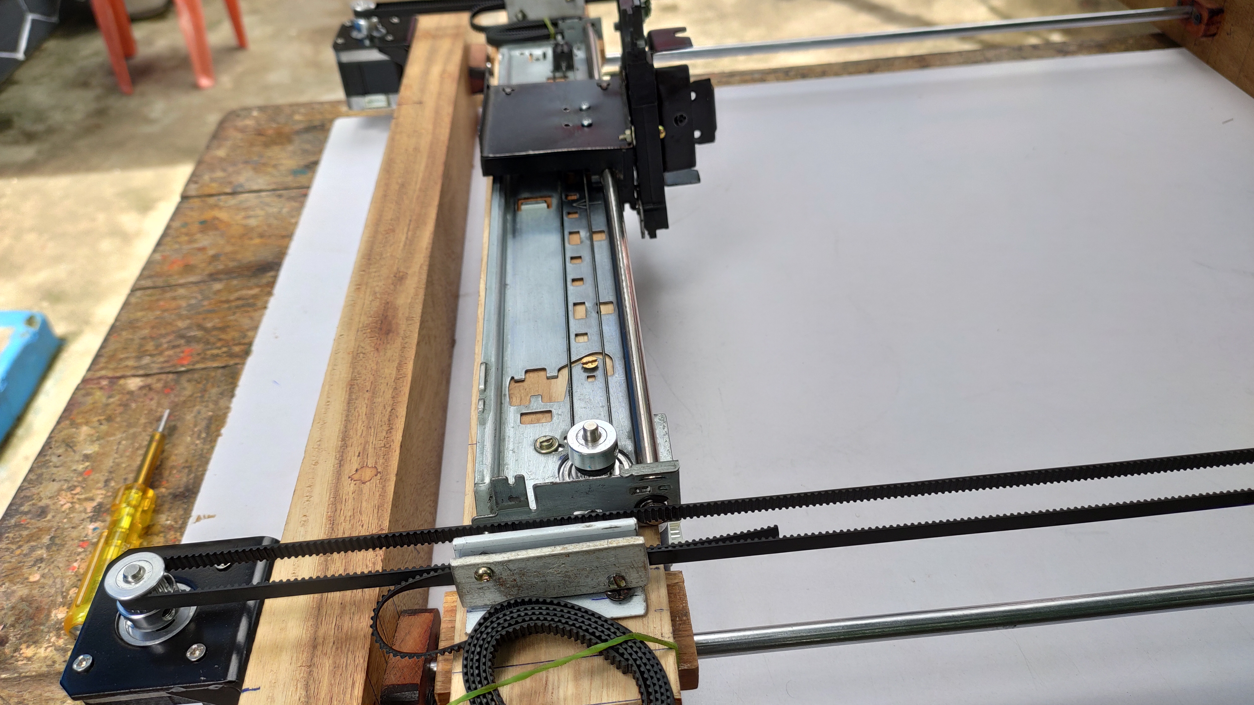
Its time to add timing belts....
The timing belts helps to move the entire x - axis platform in Y+ and Y- direction when the motor turns, Pass the belt over the idler and then back. Connect the same belt towards the toothed pulley, which we connected to the stepper motor. Take the two sides of the belt, attach it with the belt holder which we fixed already on the X-axis platform using two rectangle shaped aluminium piece. So this results into a closed loop all together. Like wise connect the other belt on the other side of the machine. It is very important to double check whether these belts are tight enough, otherwise there is a chance for missing motor steps. If there is an extra length in belt please tie it properly.
Adding Control Boards -
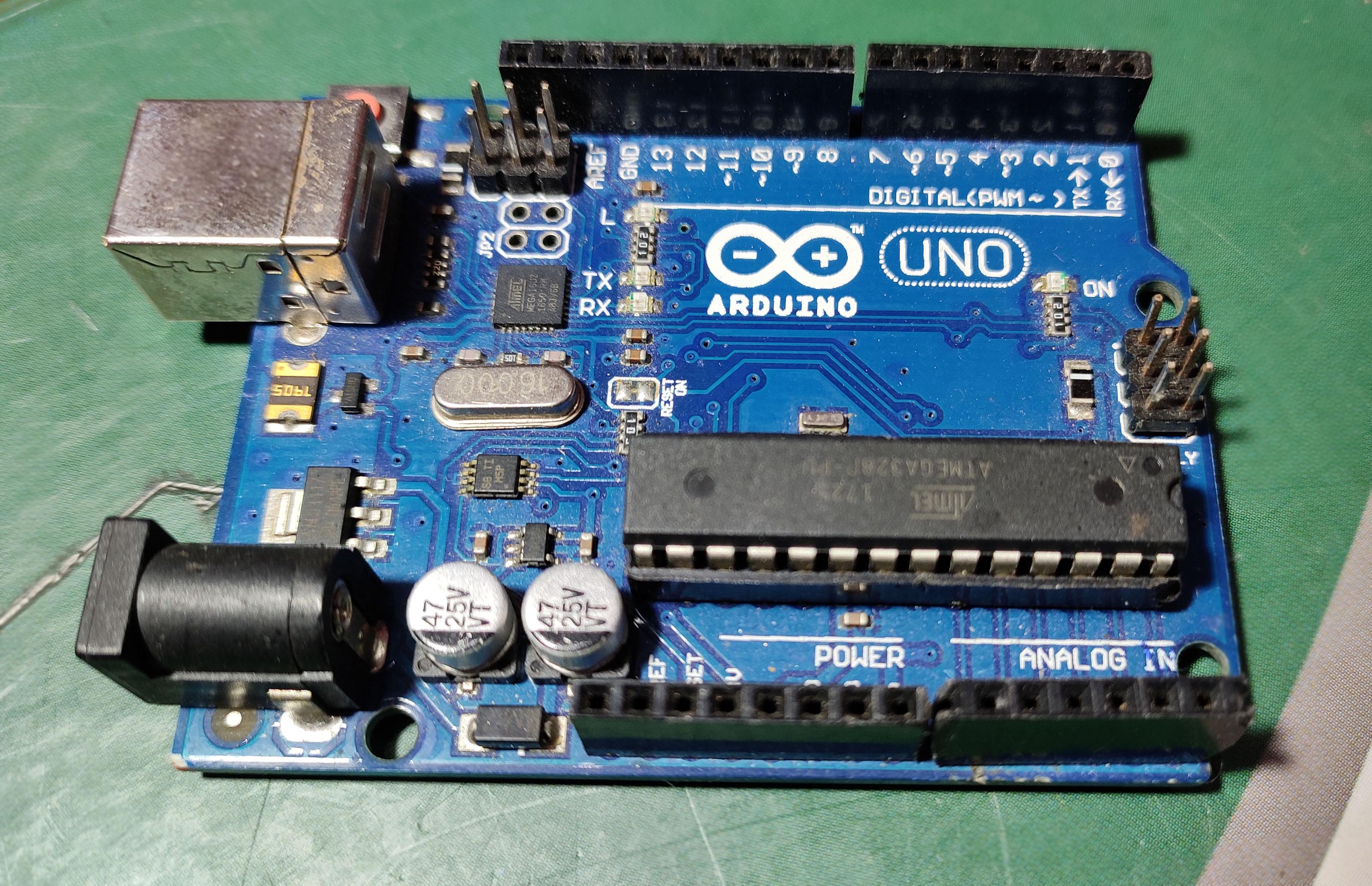
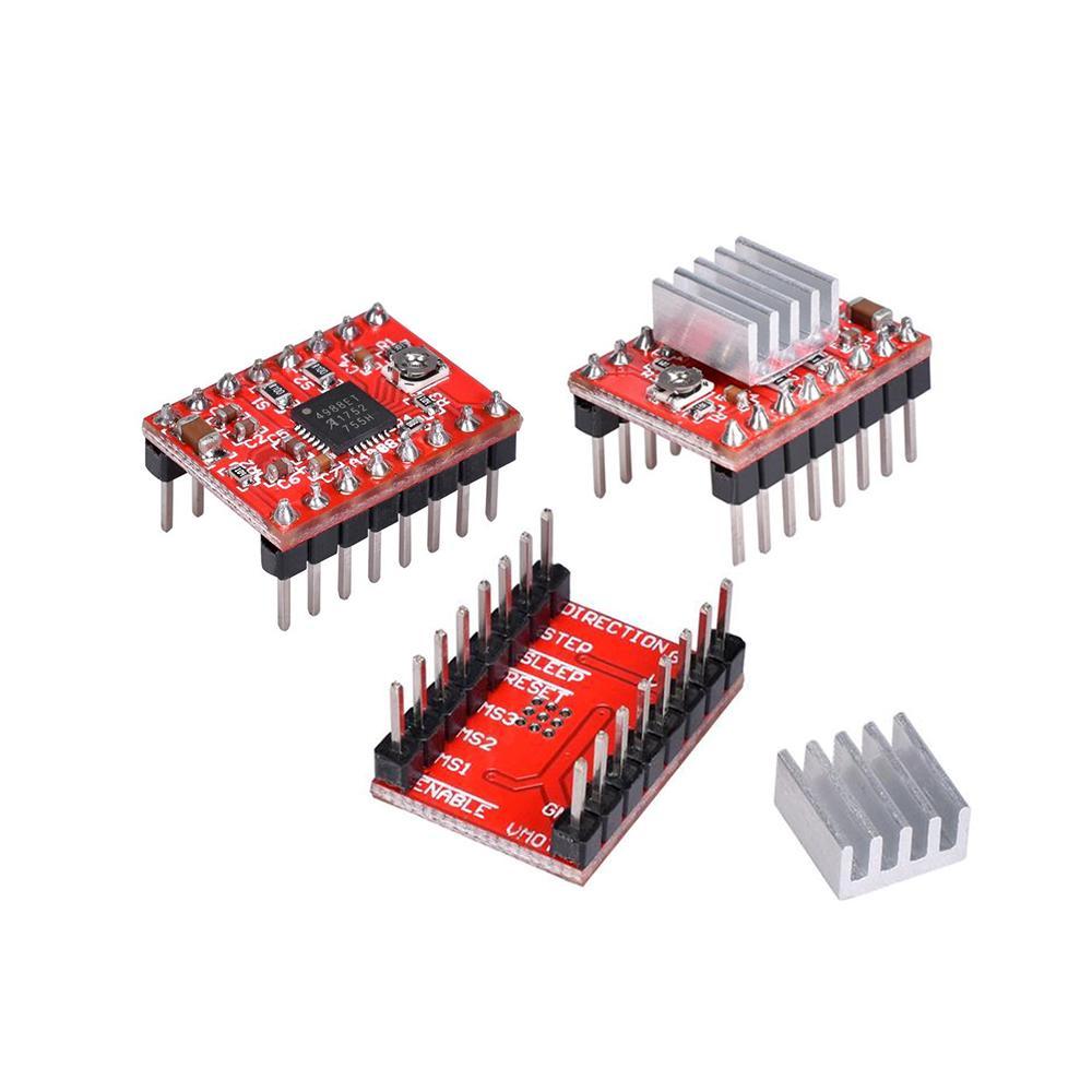
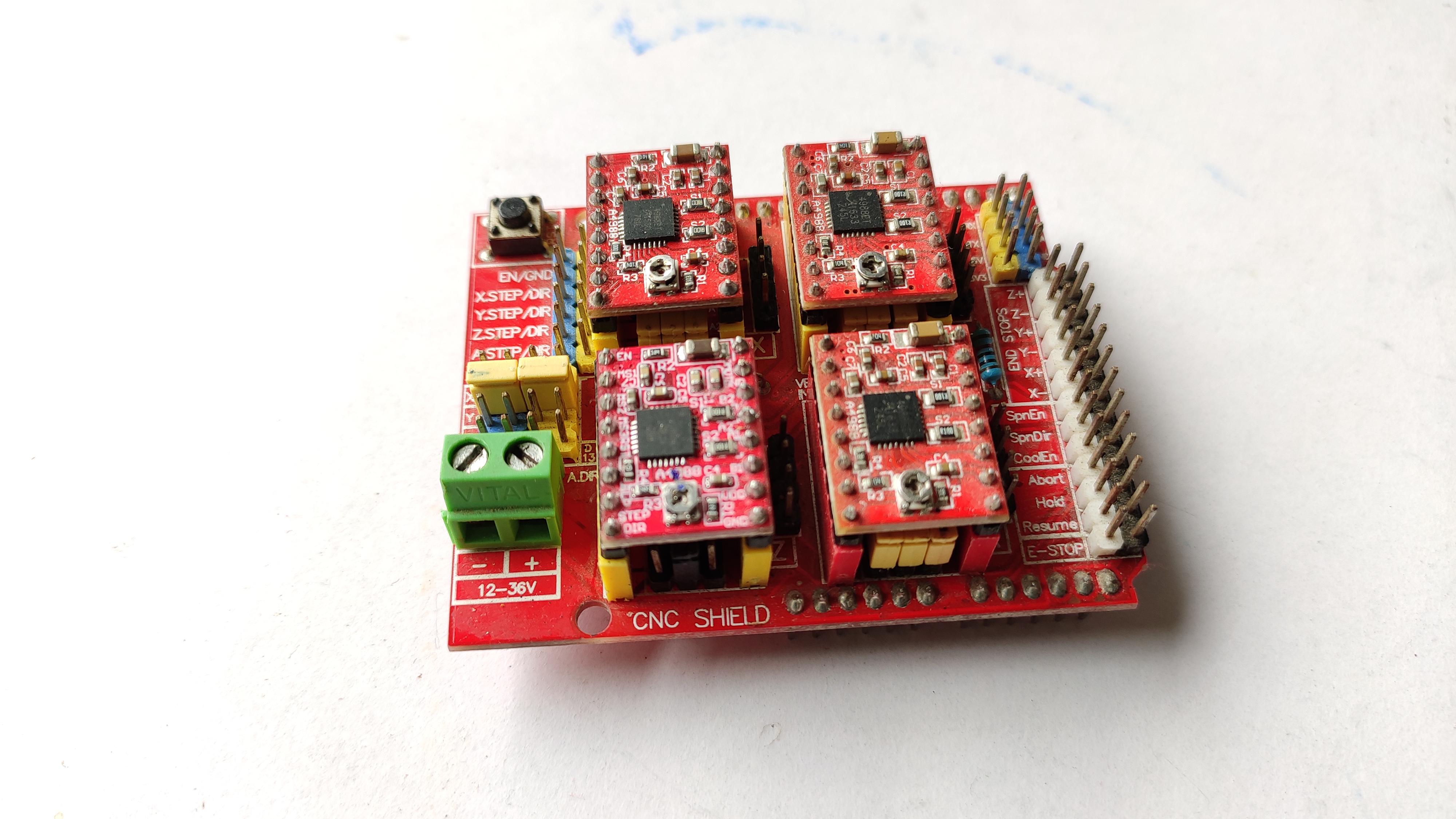
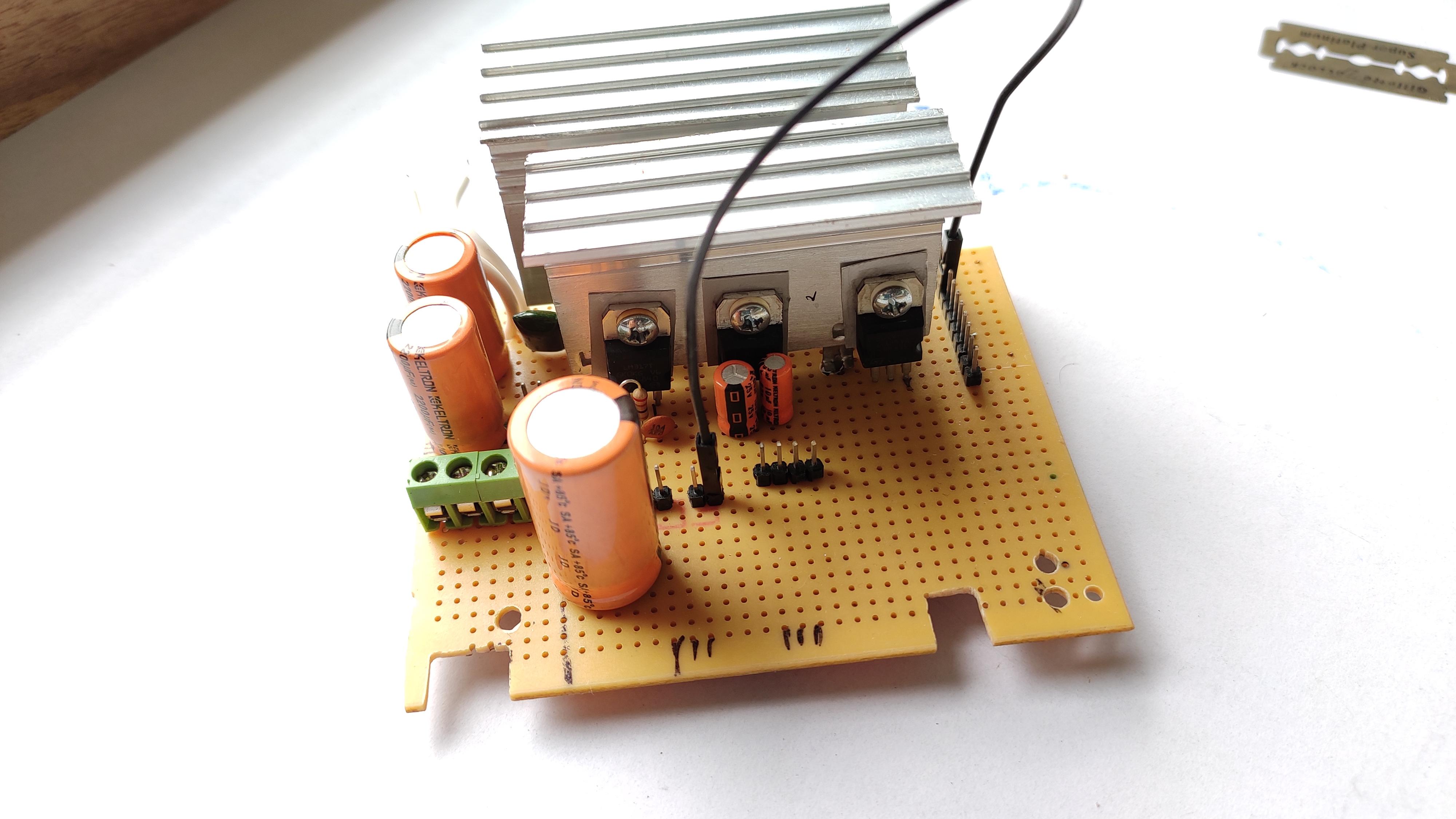
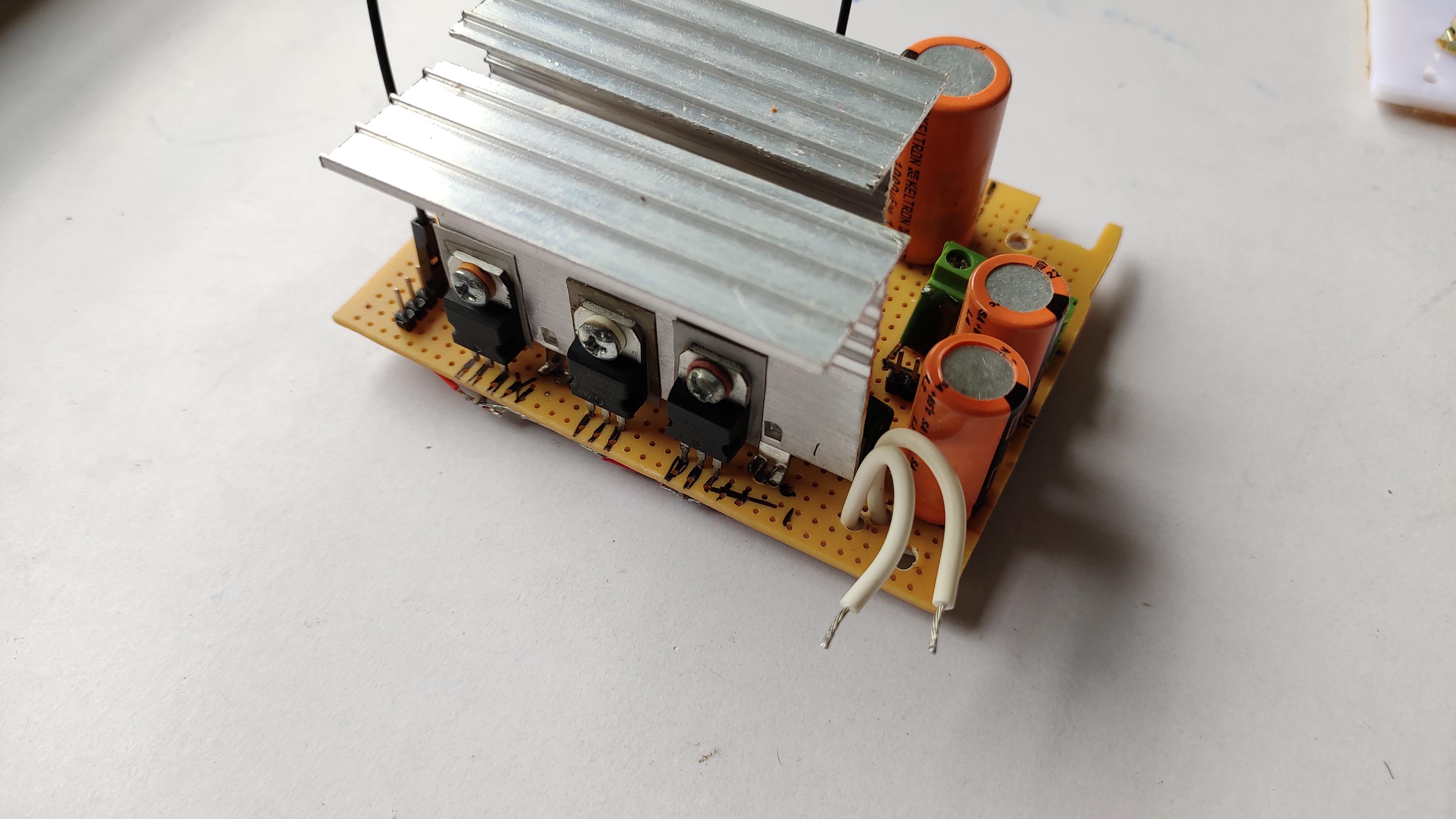
This step adds the brain to the machine.
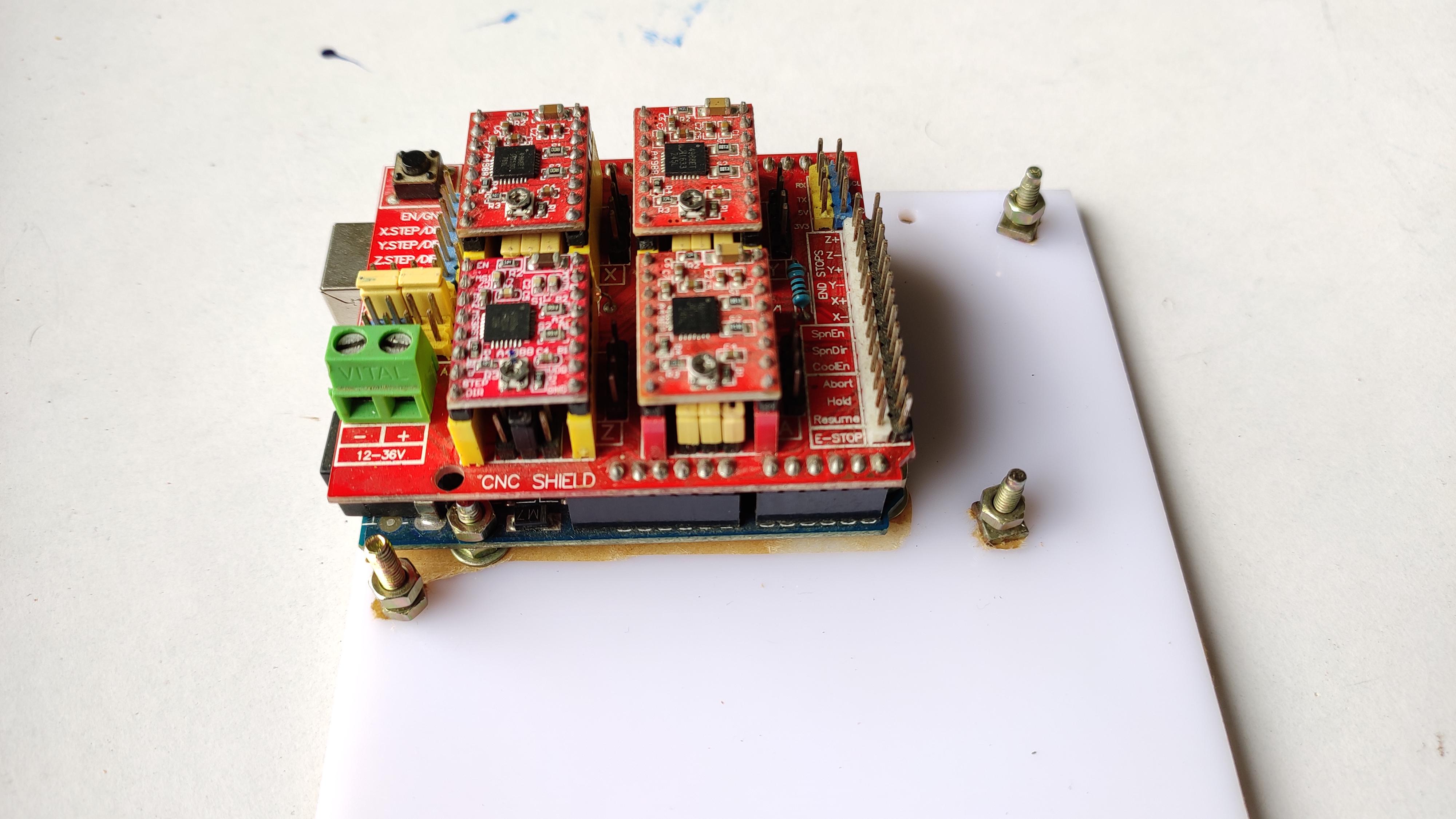
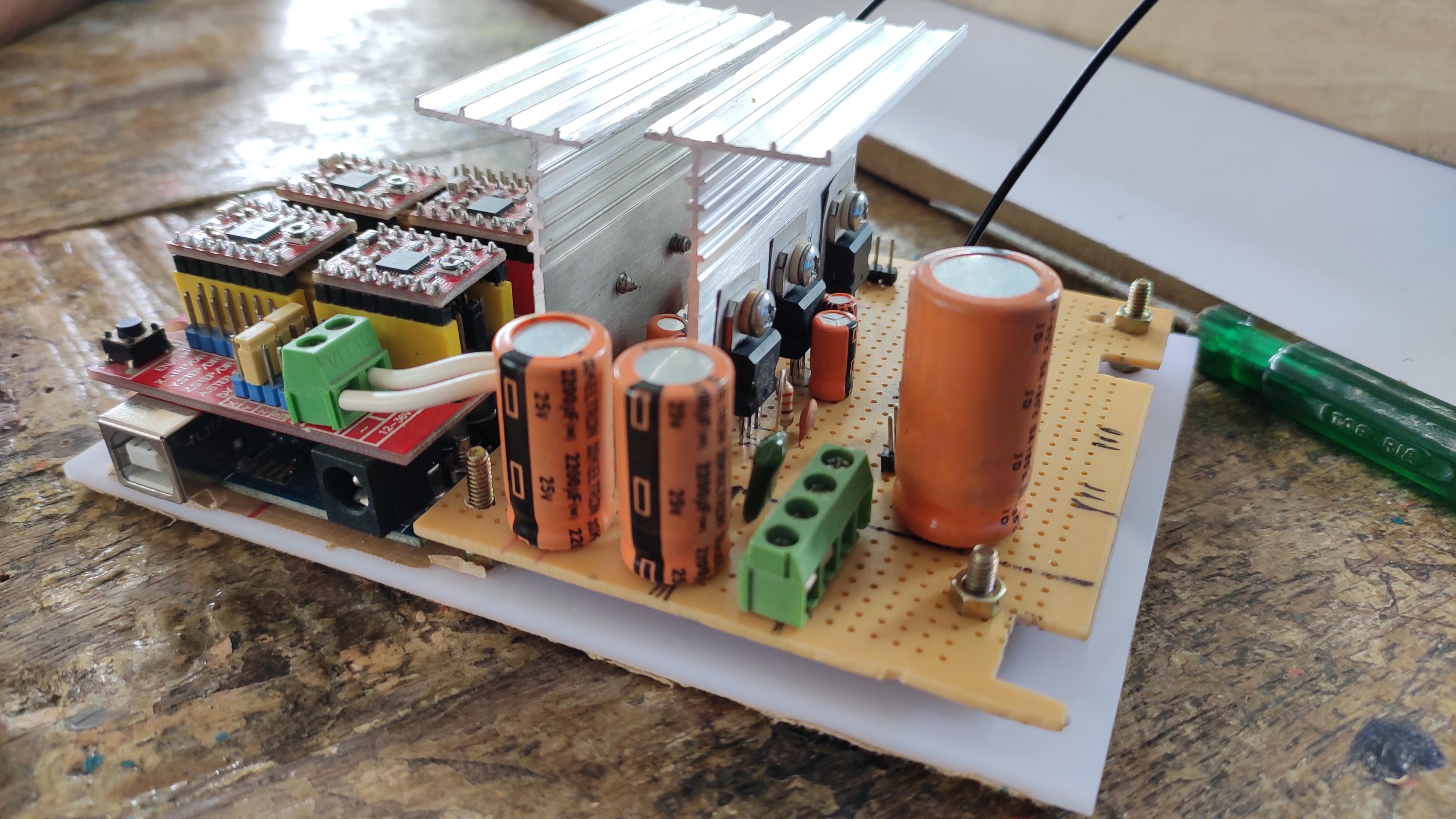
I have used Arduino UNO, A4988 stepper motor driver, A4988 compatible CNC expansion shield. And i have used the self made PCB circuit board, which will give several +5v and +12v output for the future upgrades.
Detailing the power circuit, it is used to filter the input DC voltage to the expansion shield, has VCC output pins for Arduino VCC, Bluetooth module, Relay module, if you use it for future. Plus has LM317 voltage regulator IC able to control the speed of the cooling fan. Carefully attach the Expansion shield over the arduino satisfying the correct pins to be matched. And then attach the stepper driver over the shield. You can use ON/OFF toggle switch, status led etc...
Making an Enclosure - Attaching Power Supply for Electronics:
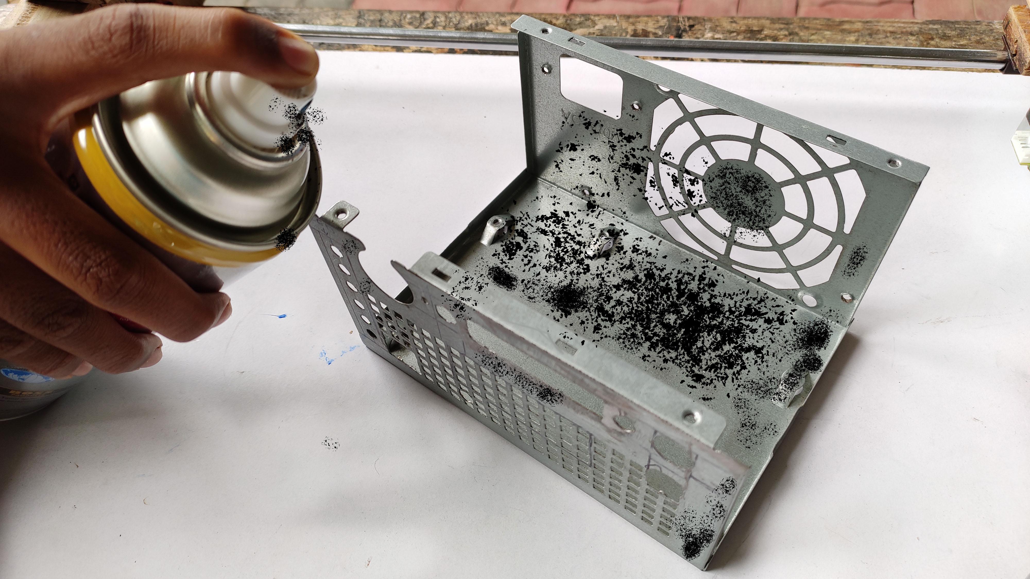
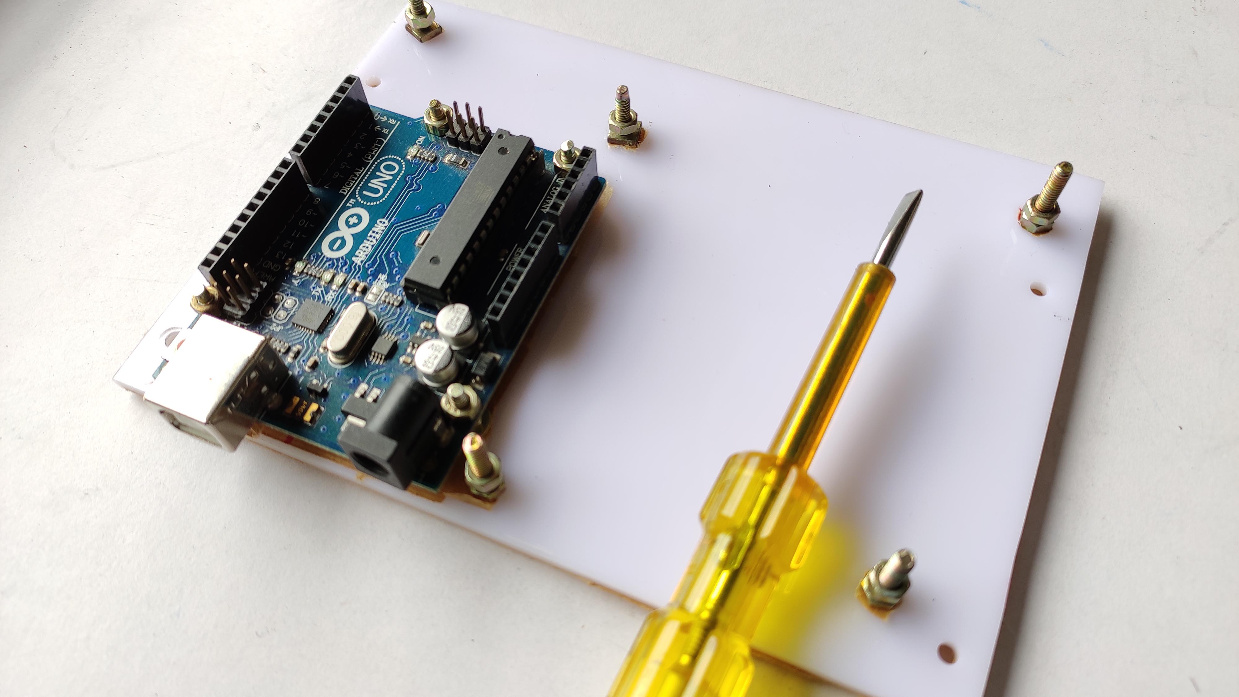
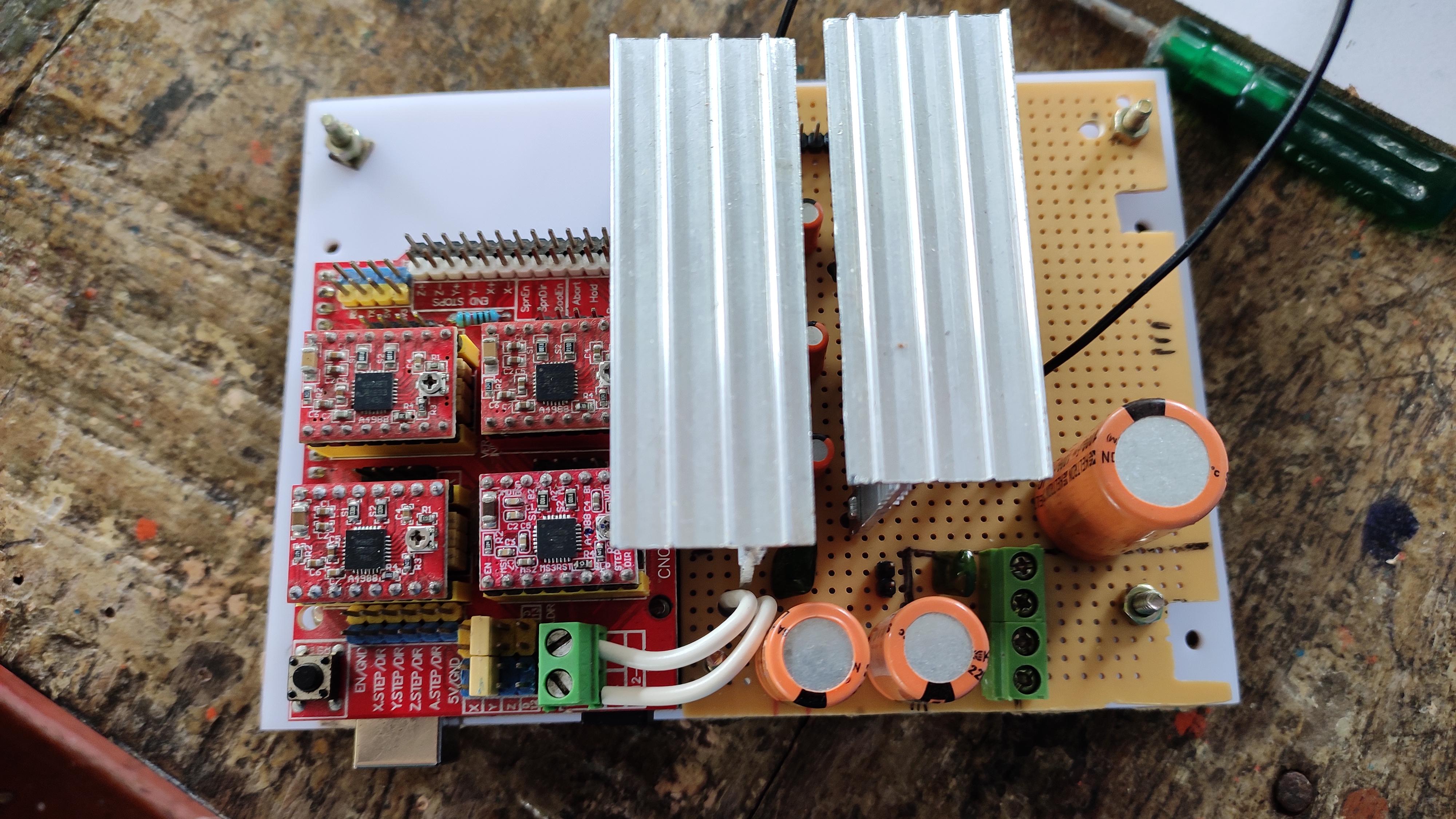
Whether we can put all these electronics into a box/enclosure ?
yes, come on, lets make one.
Take an old computer smps power supply.
Remove all the unwanted PCB board in it, Take out only the aluminium box out, clean it thoroughly, if need spray paint on it, gives the look.
Make a base platform for the arduino and all others, keep the same inside the box, Connect the external supply by without changing the polarity, repeating, connect without changing polarity.
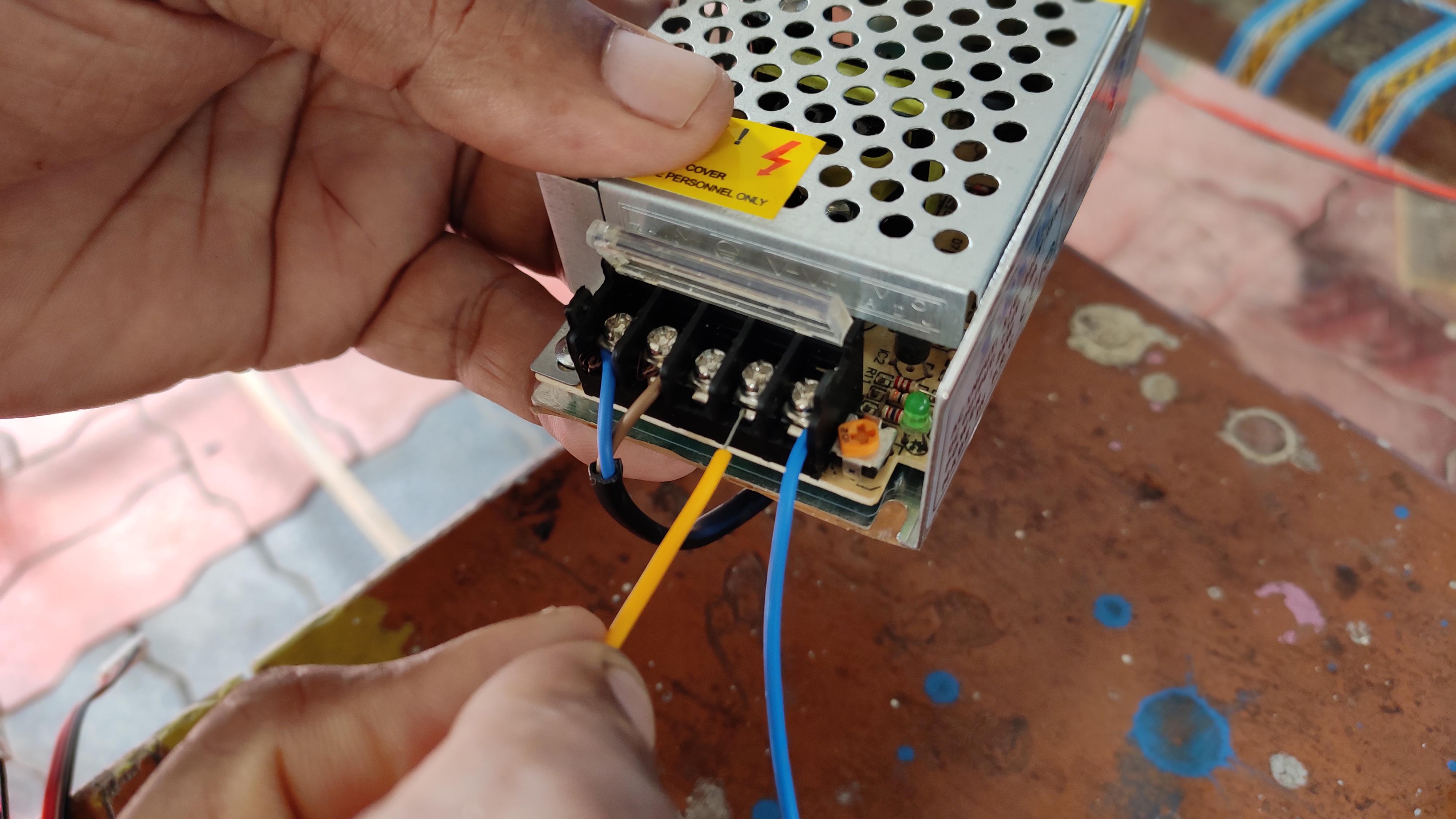
Choosing a apt power supply is challenging, i have taken +12v 2A 25w power supply, Connect the input AC to the slot, where marked 'L' on the supply. And connect the output +12v to the PCB circuit, If you are connecting through your own made power circuit, before connecting make sure that the circuit do not have any short circuit lines.
Wiring
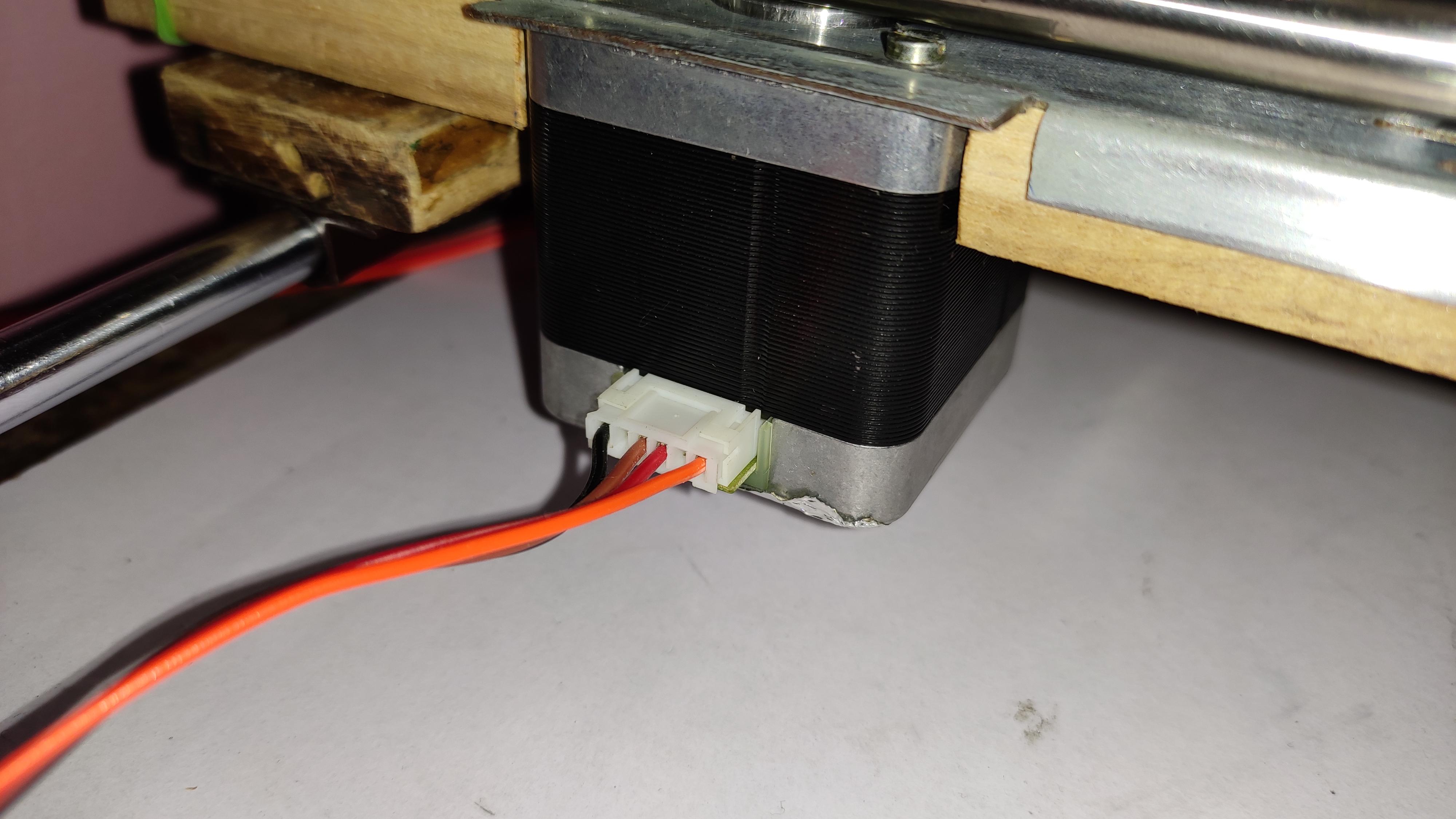
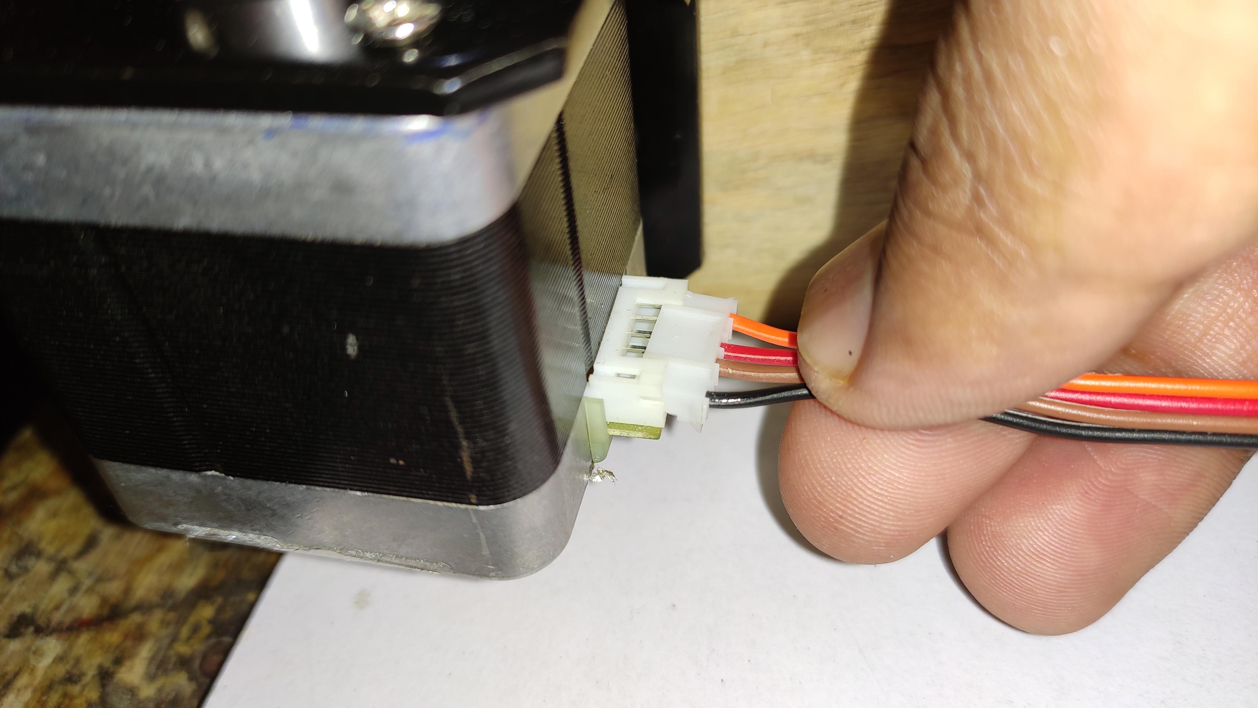
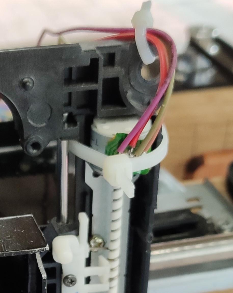
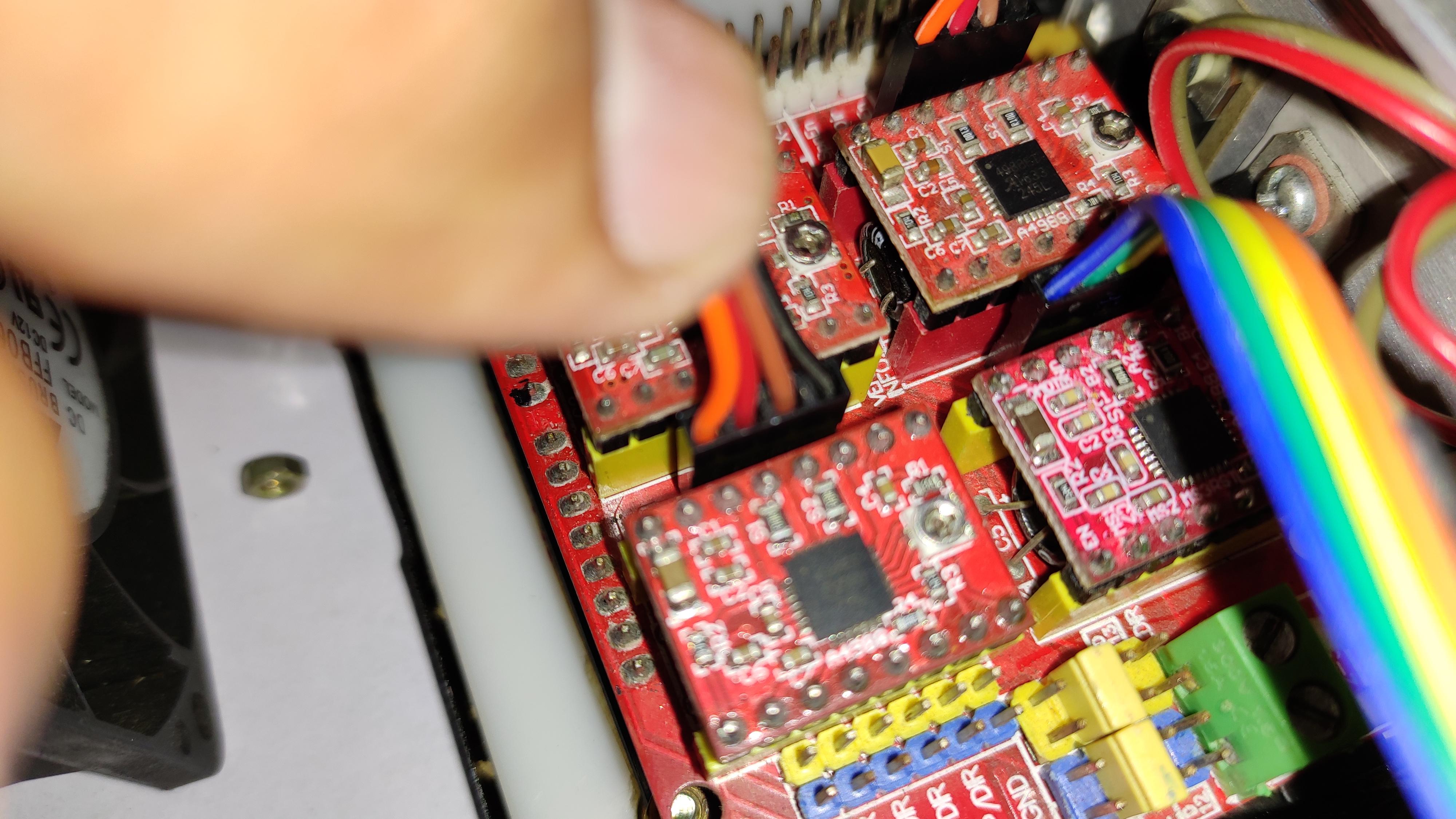
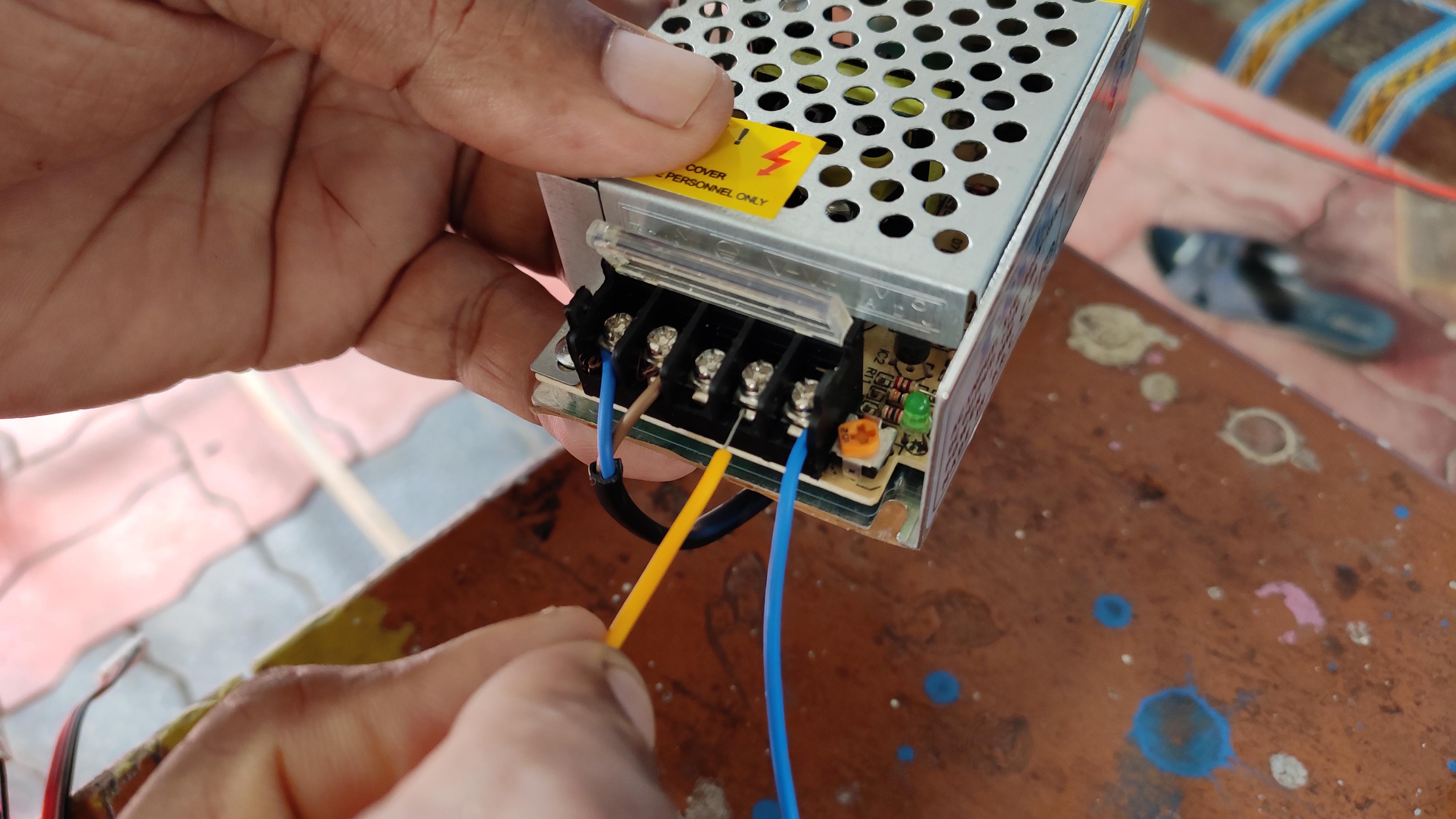
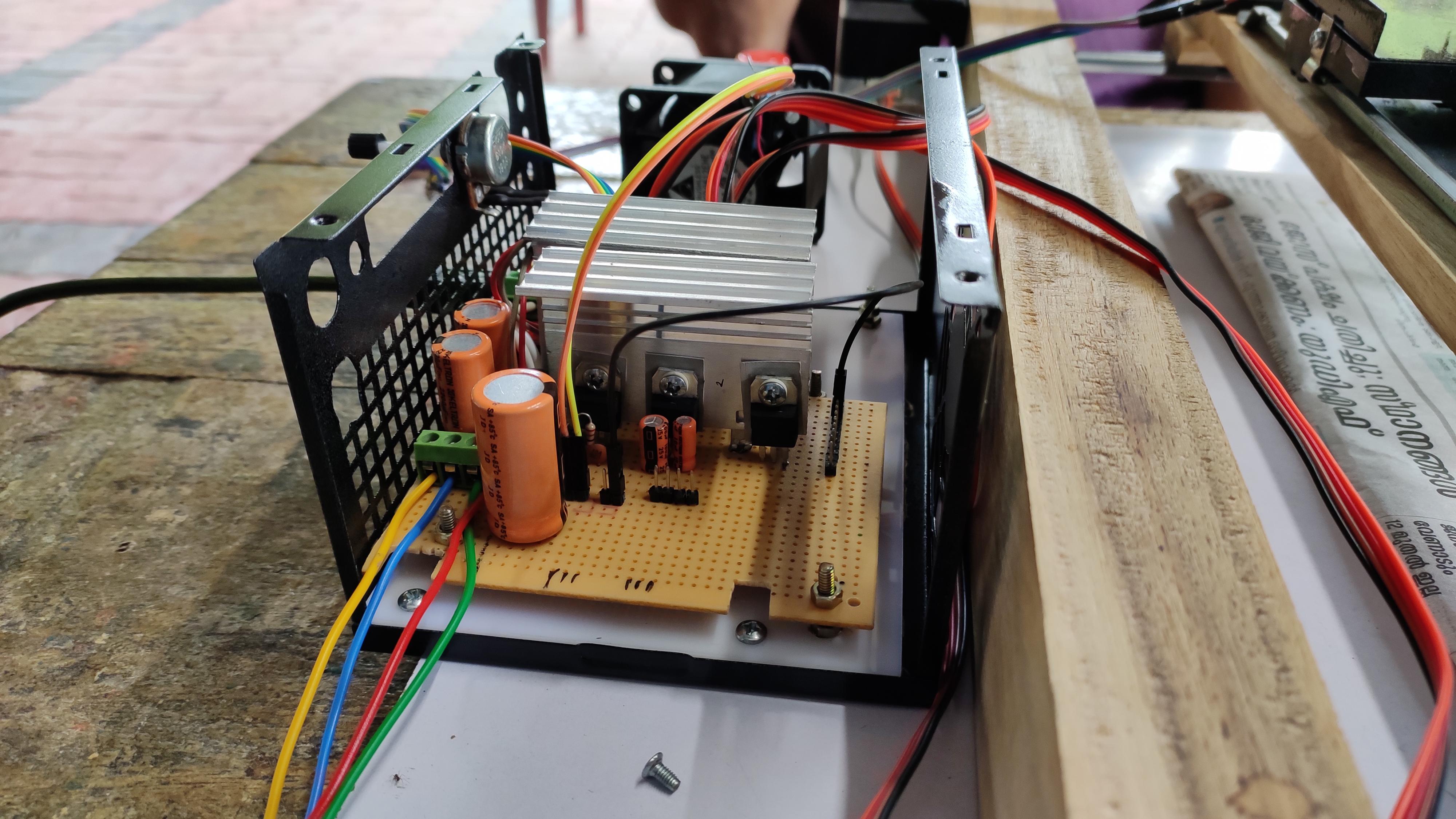
Here comes the wiring section :-
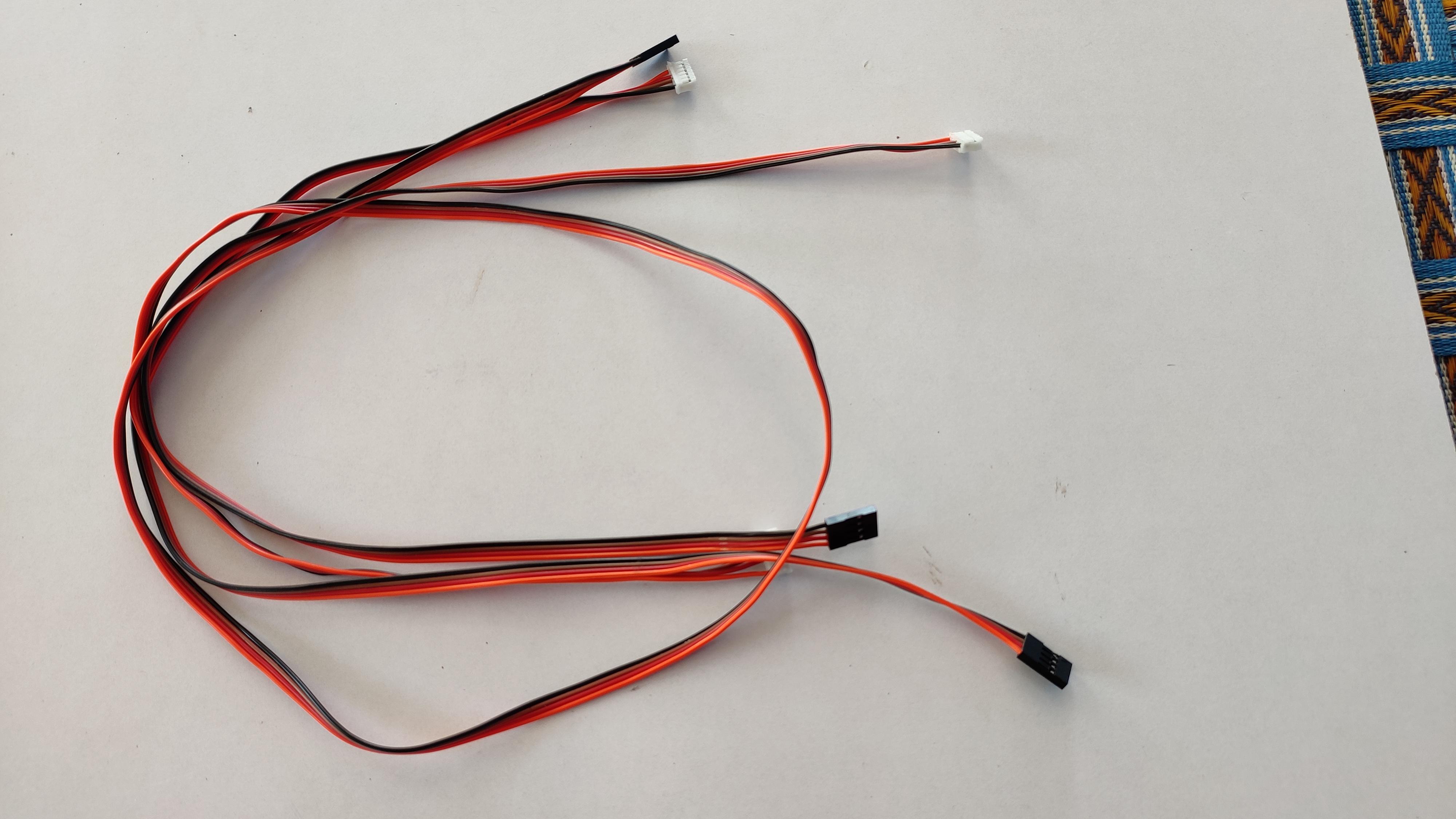
I have used the same wires which i got with the stepper motors, i had to make one for my Z-axis motor, made using jumper wires, easy.....
Properly connect the coil wires to the stepper motor, i.e connect the two wires from the same coil to the [1A,1B] pin and other to [2A,2B] pin
attach some heat sink to the driver and also for the z-axis stepper motor, sometimes there is a chance for overheating z-axis motor because of the smaller size, it cant withstand much amps. So always using the one will helps to clear out the future heat related problems.
Please check the pin configuration of A4988 here
-> A4988 pin-https://components101.com/
Check for the CNC expansion shield guide here
Adding a Final Touch:
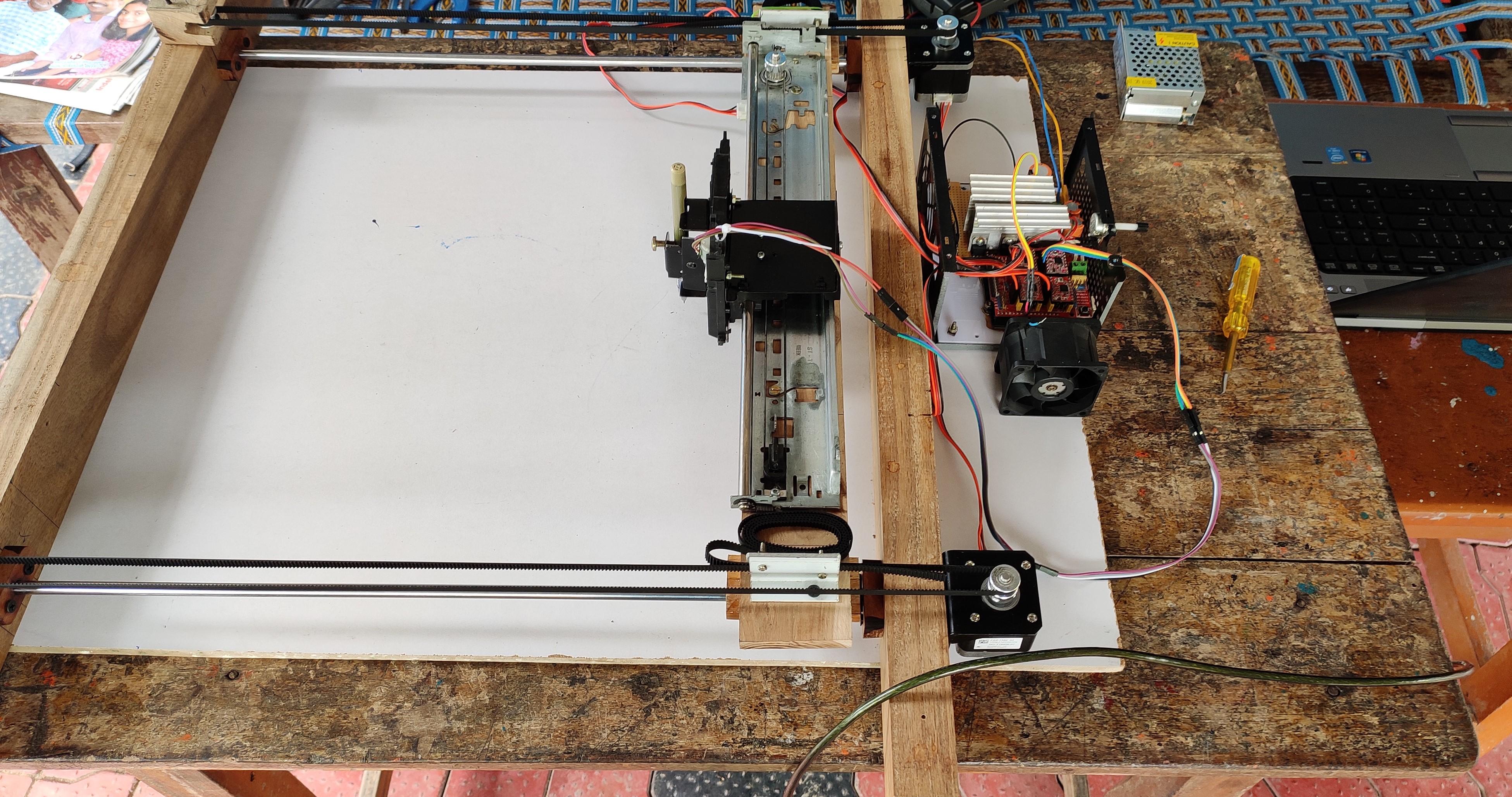
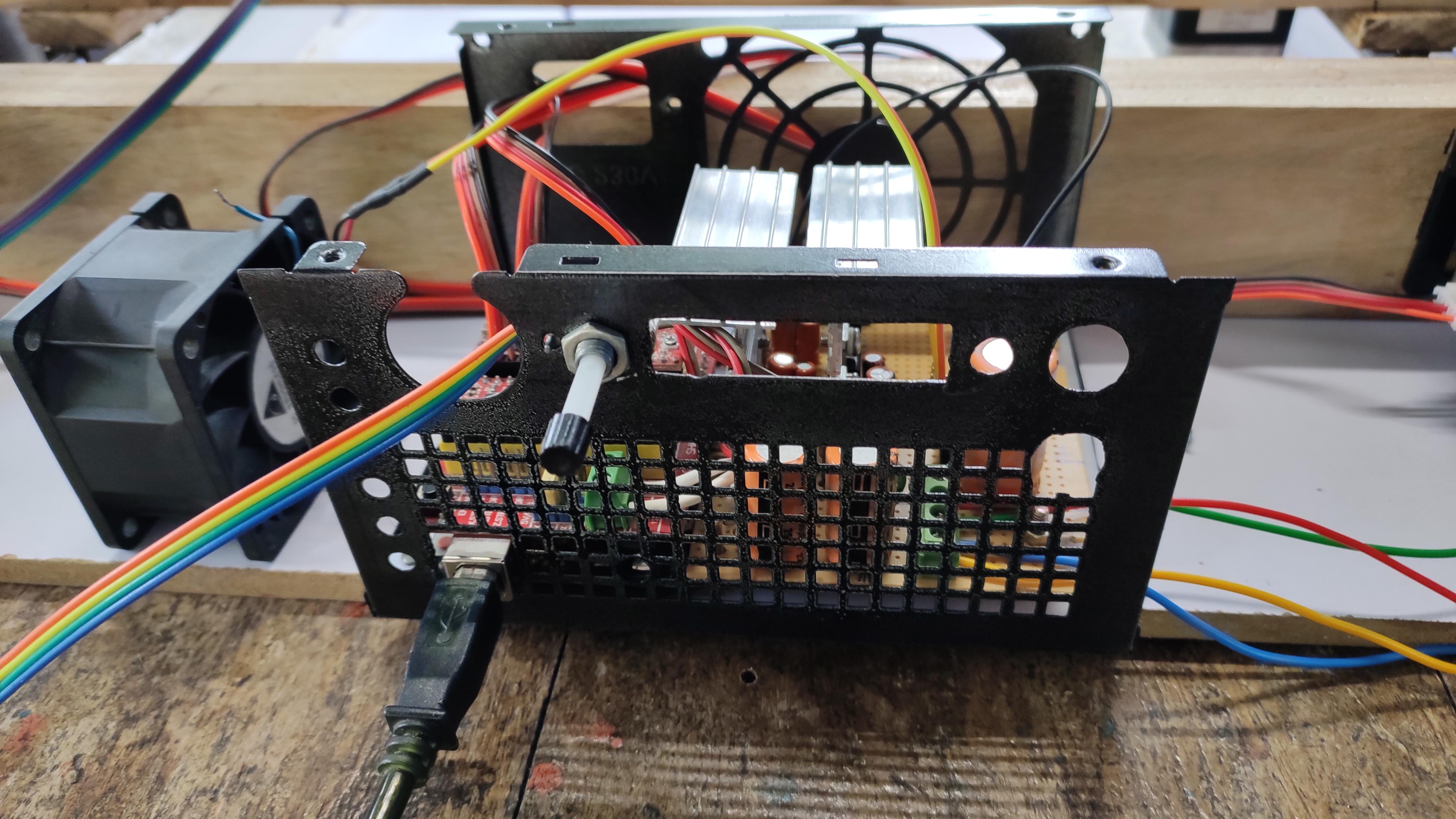
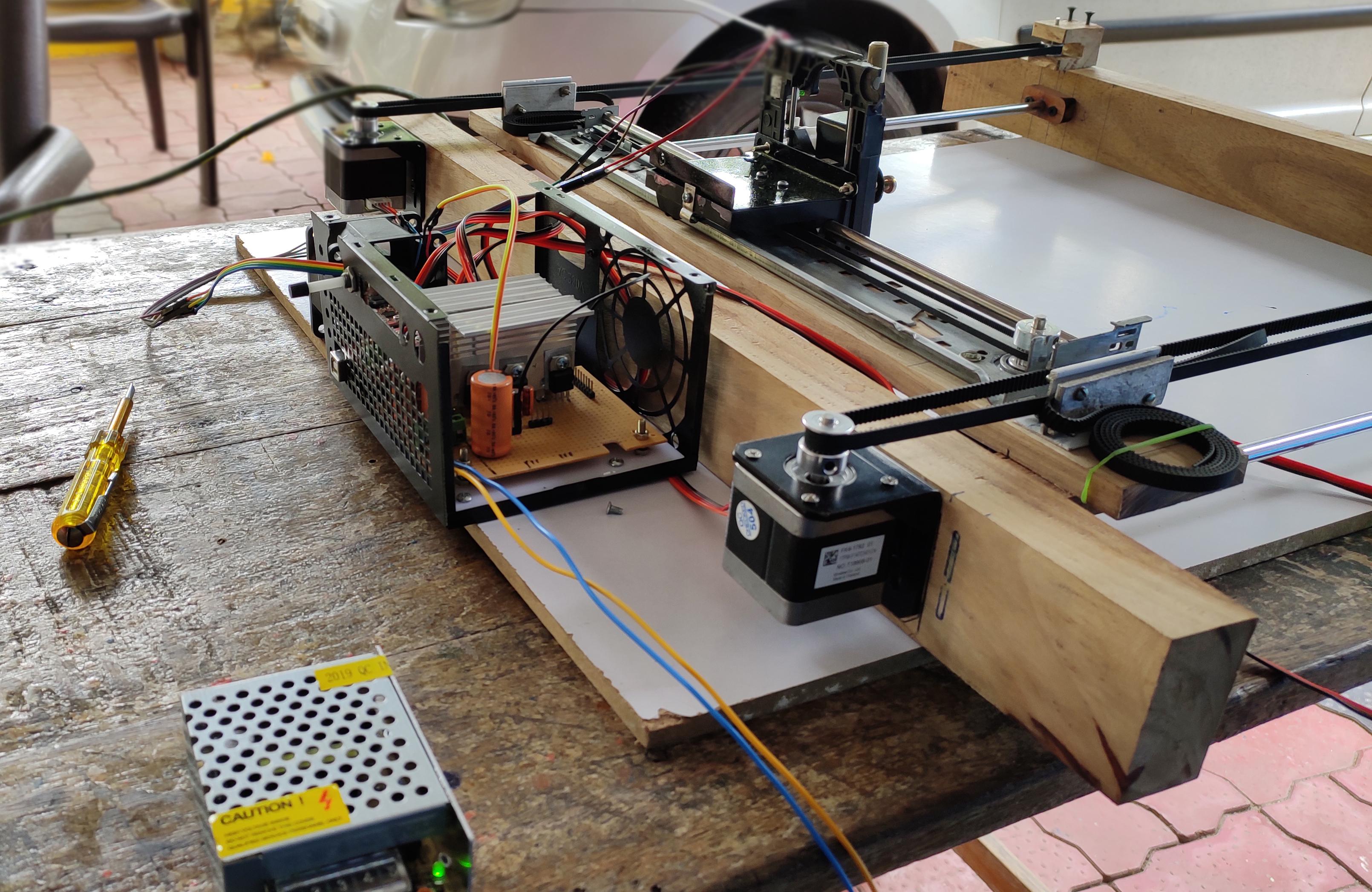
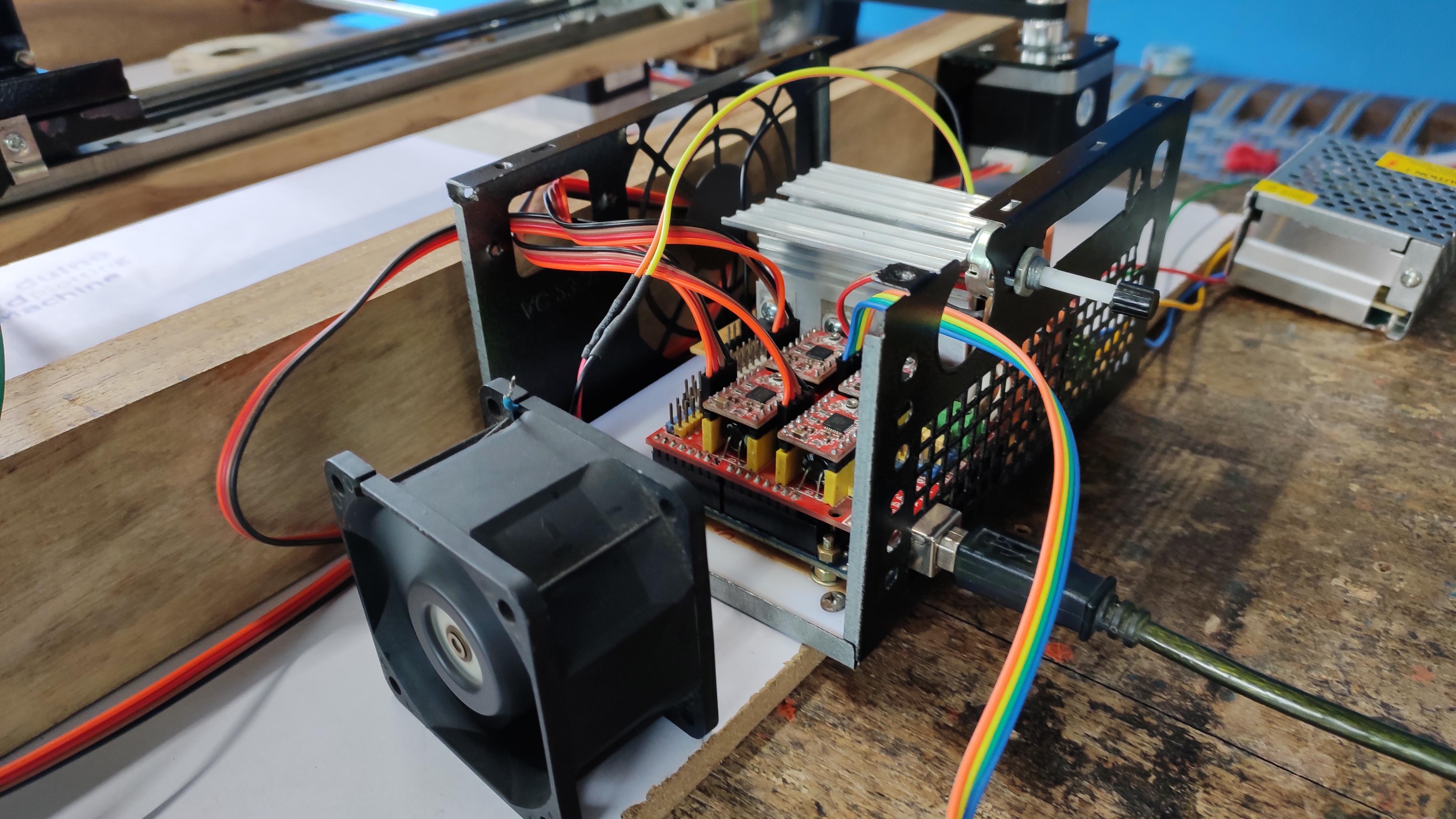
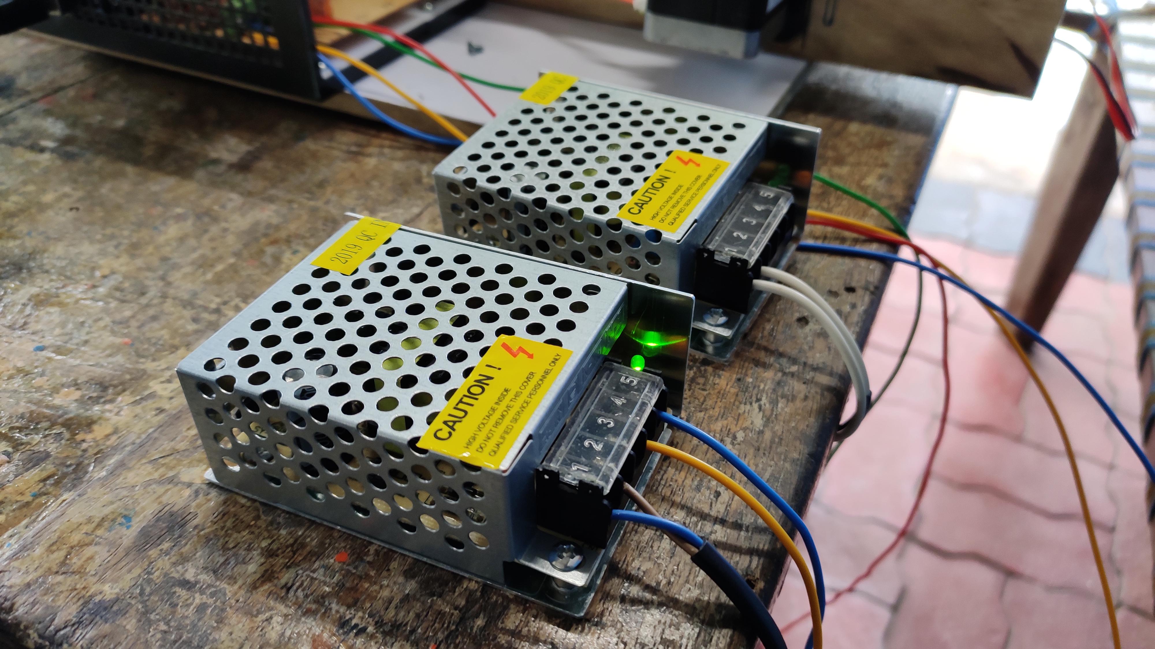
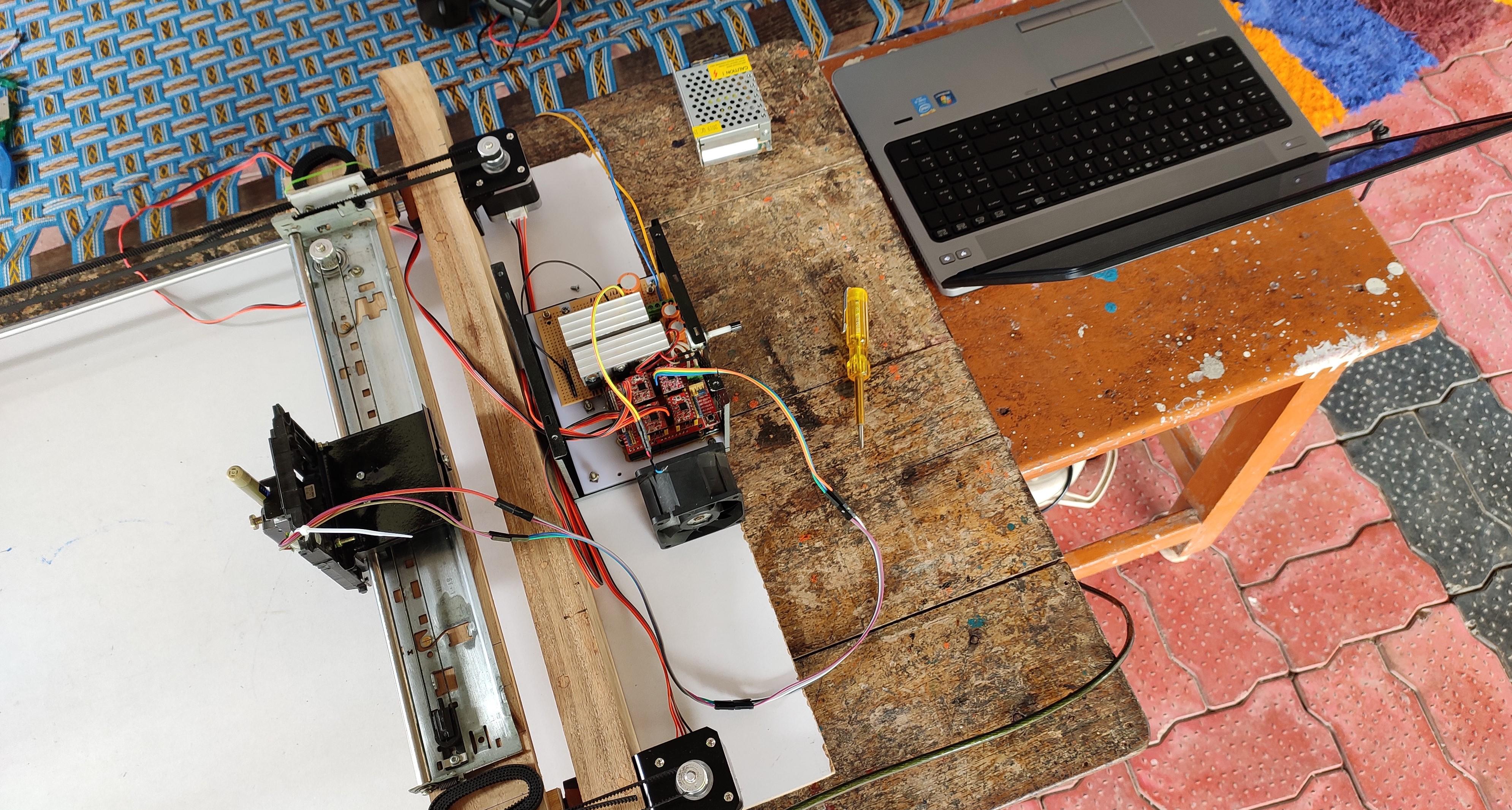
Wow, almost done.
So, lets arrange all these stuff in an correct order/place.
Correct all the wires, put those in proper place, Make sure that no wires are bend, under the wooden frame.
Place the cooling fan in such a position that the drivers can receive more air circulation.
Connect one end of the data cable to arduino and other to the PC/laptop serial port. And one more thing- adjust the z+/z- height, At first run there is a chance to hit .
Uploading & Configuring GRBL to Arduino
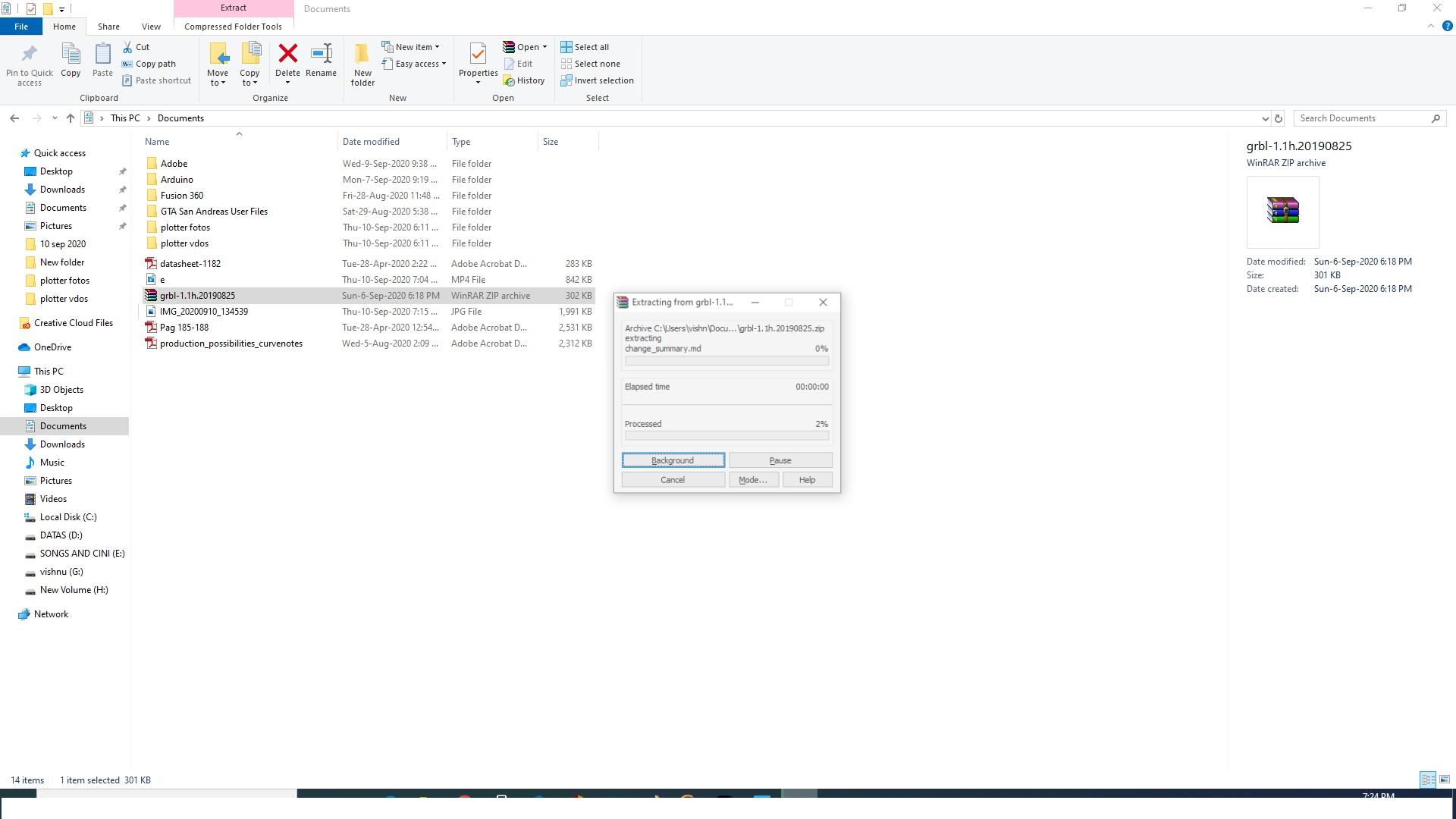
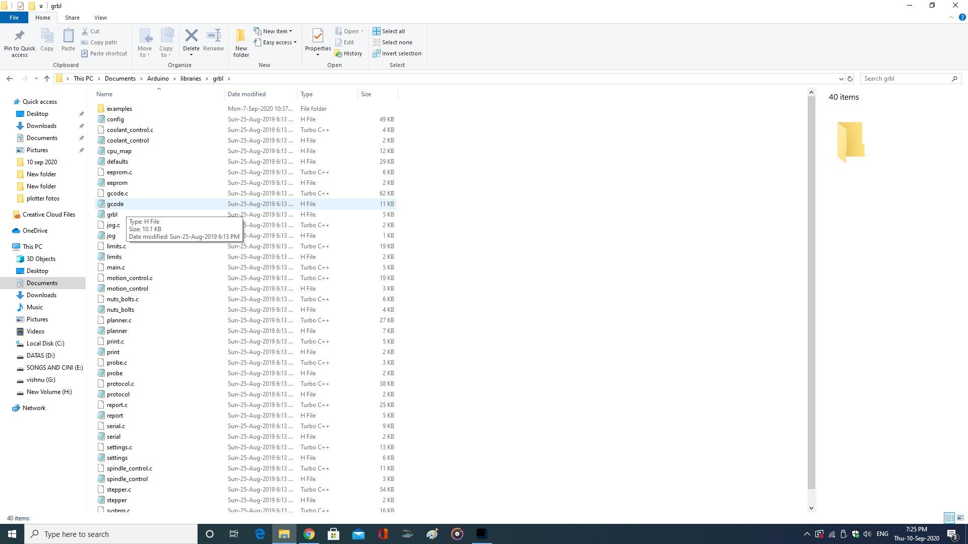
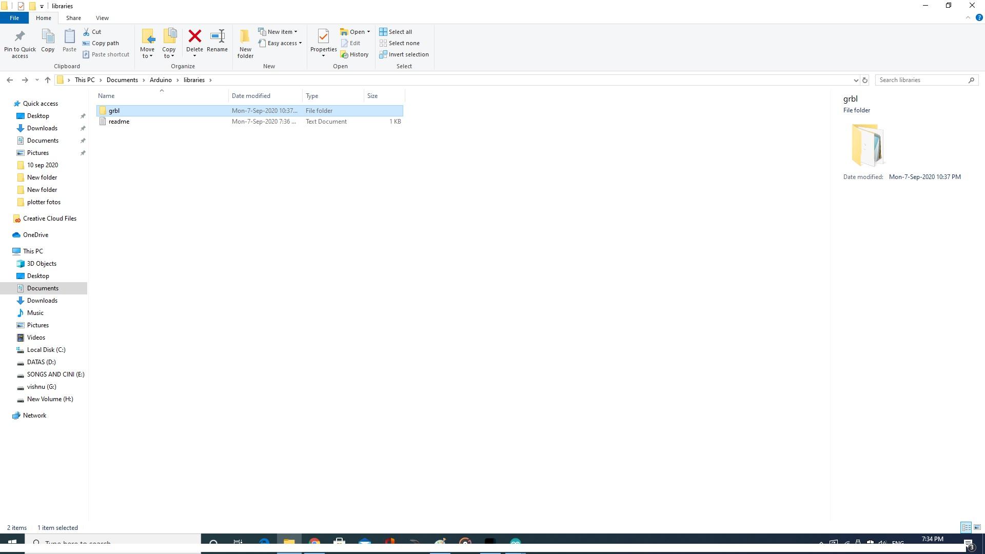
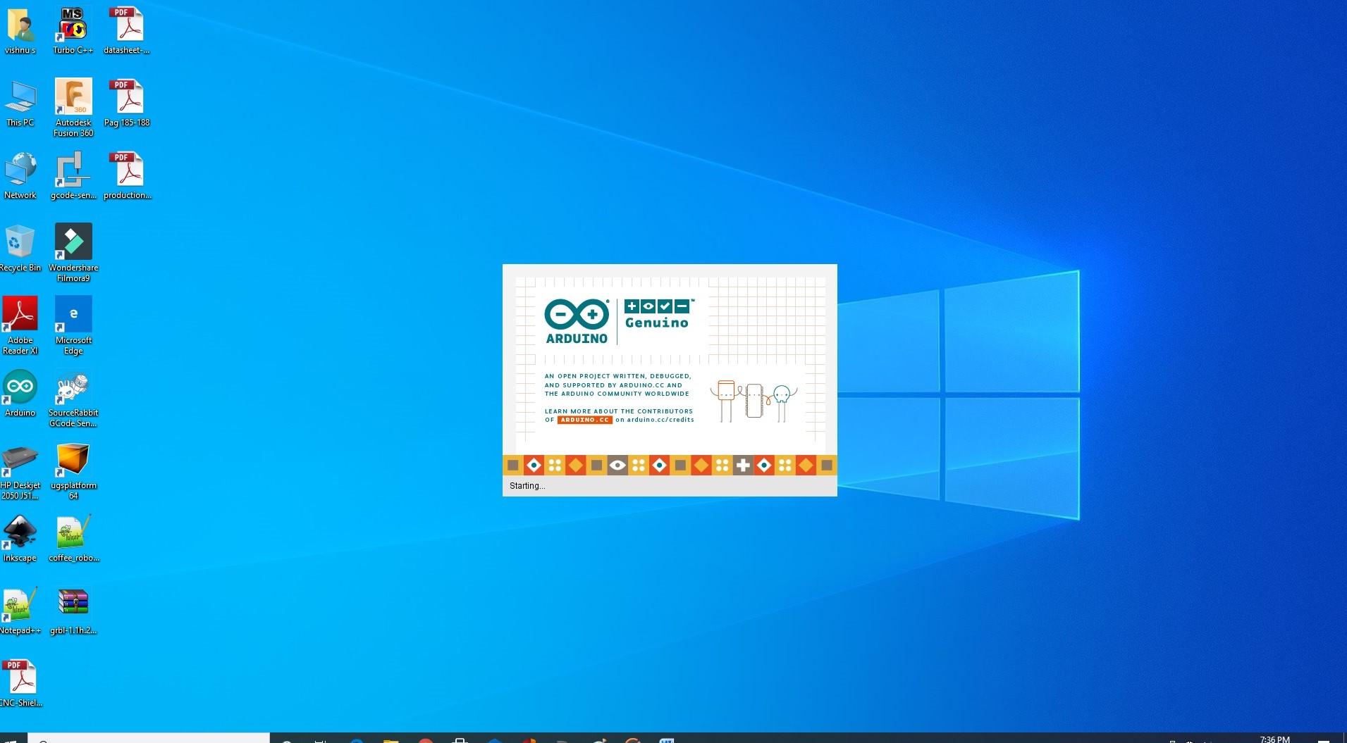
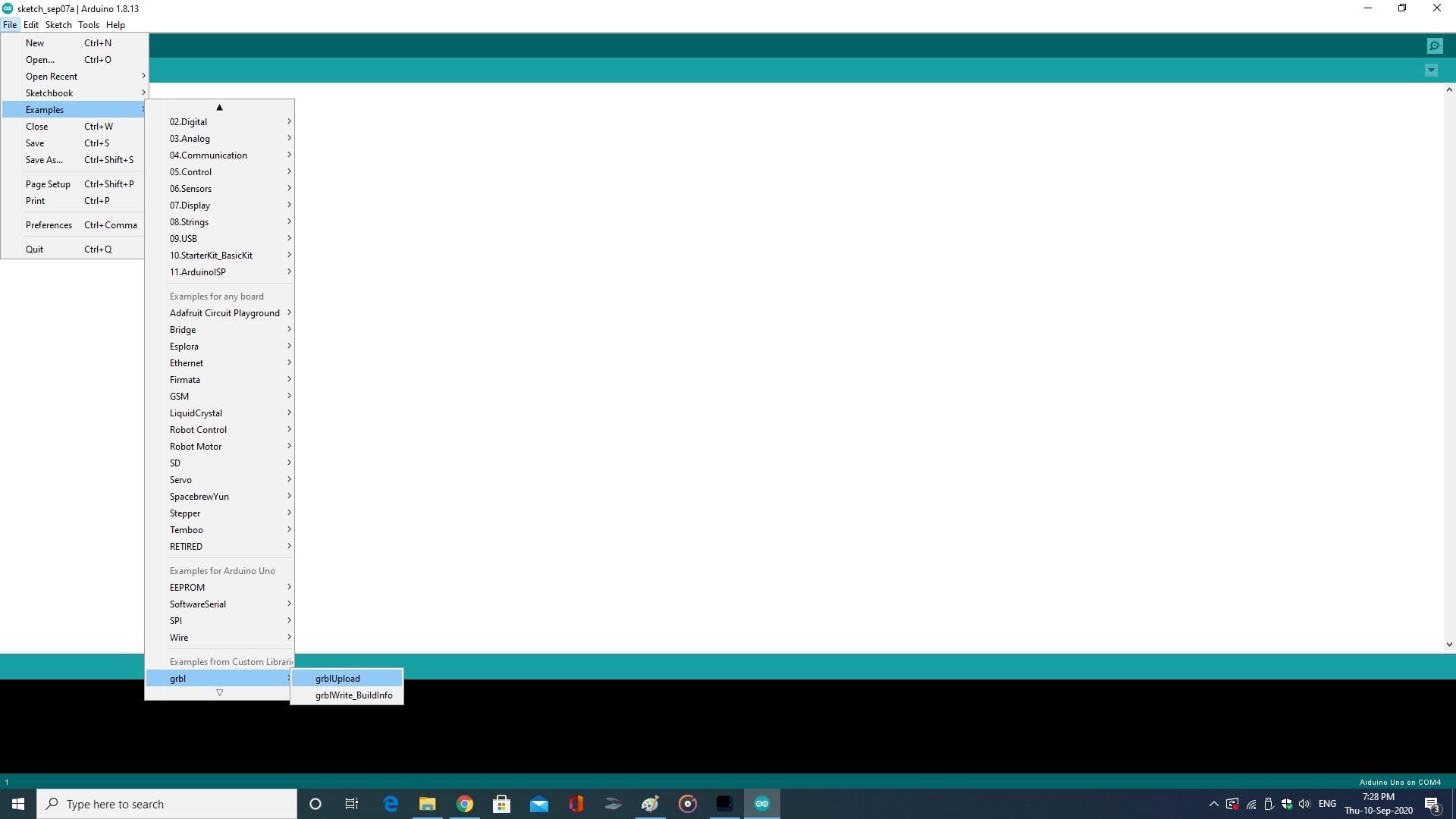
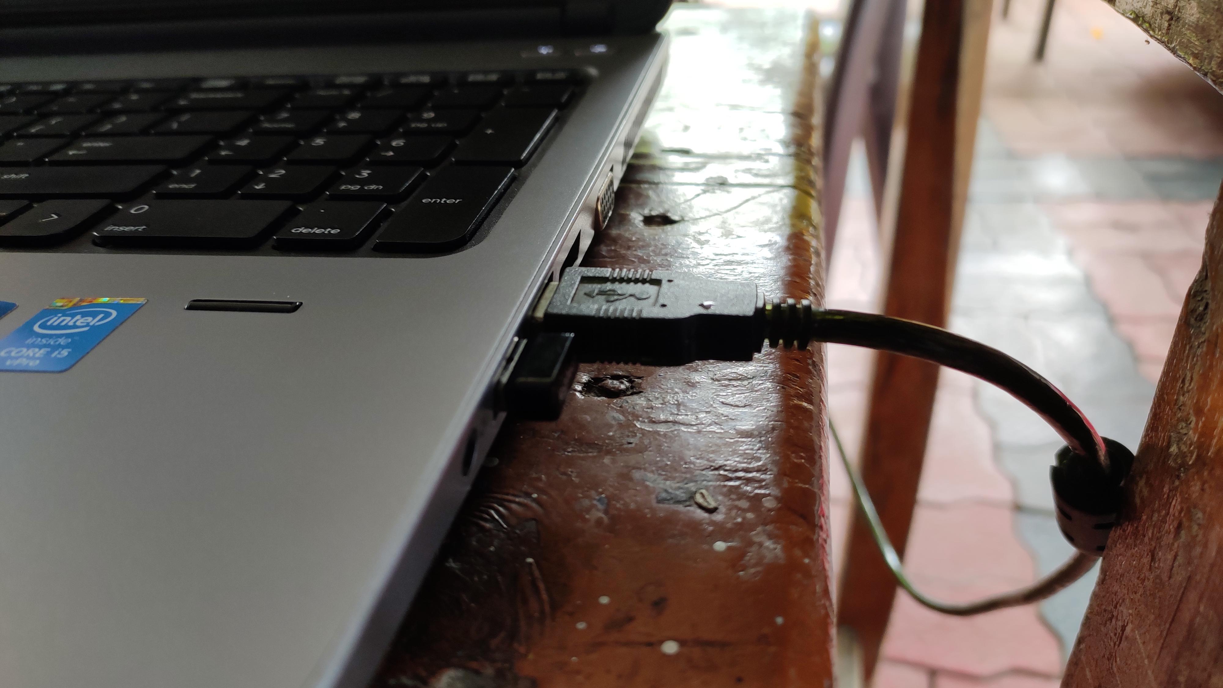
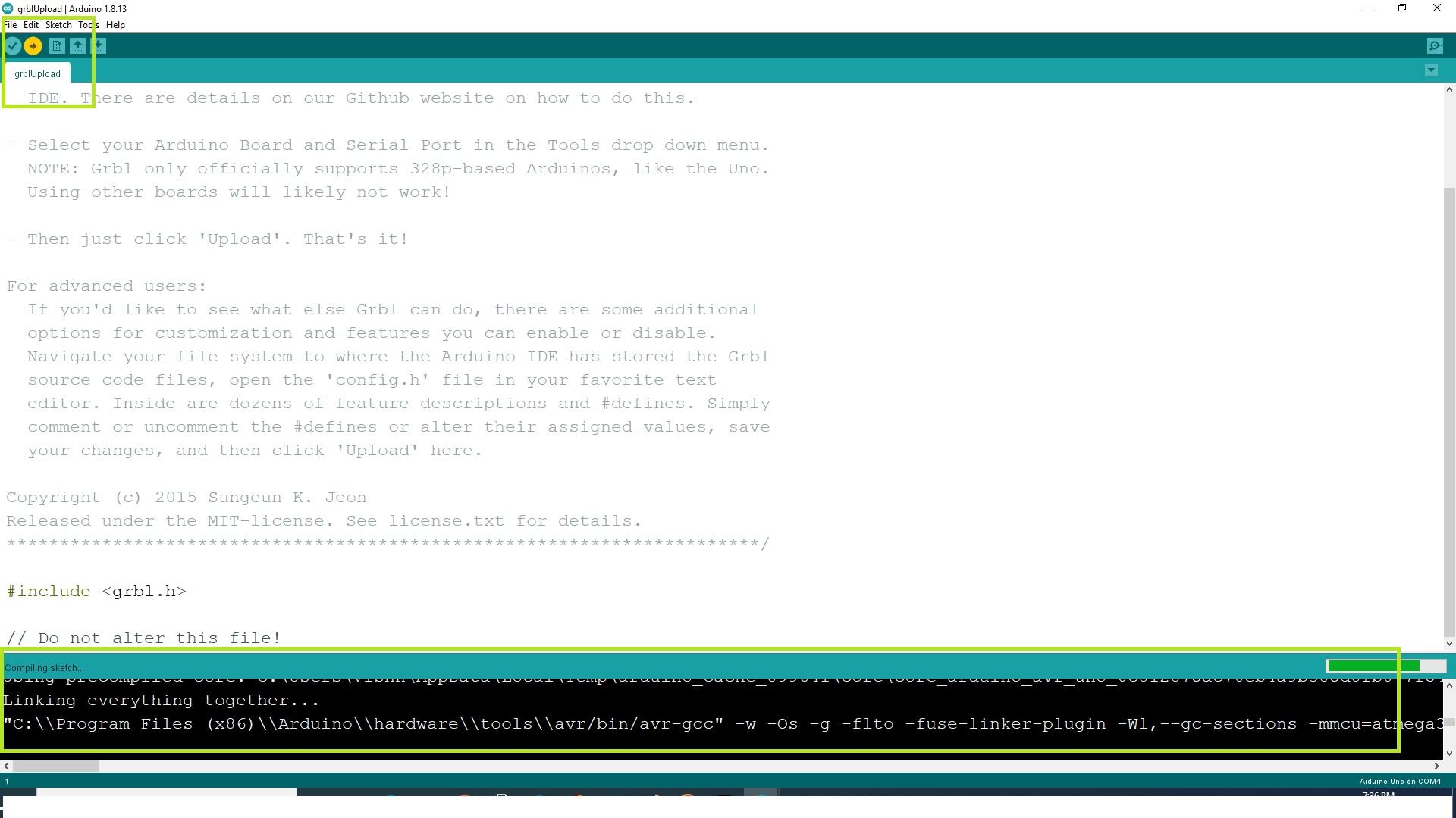
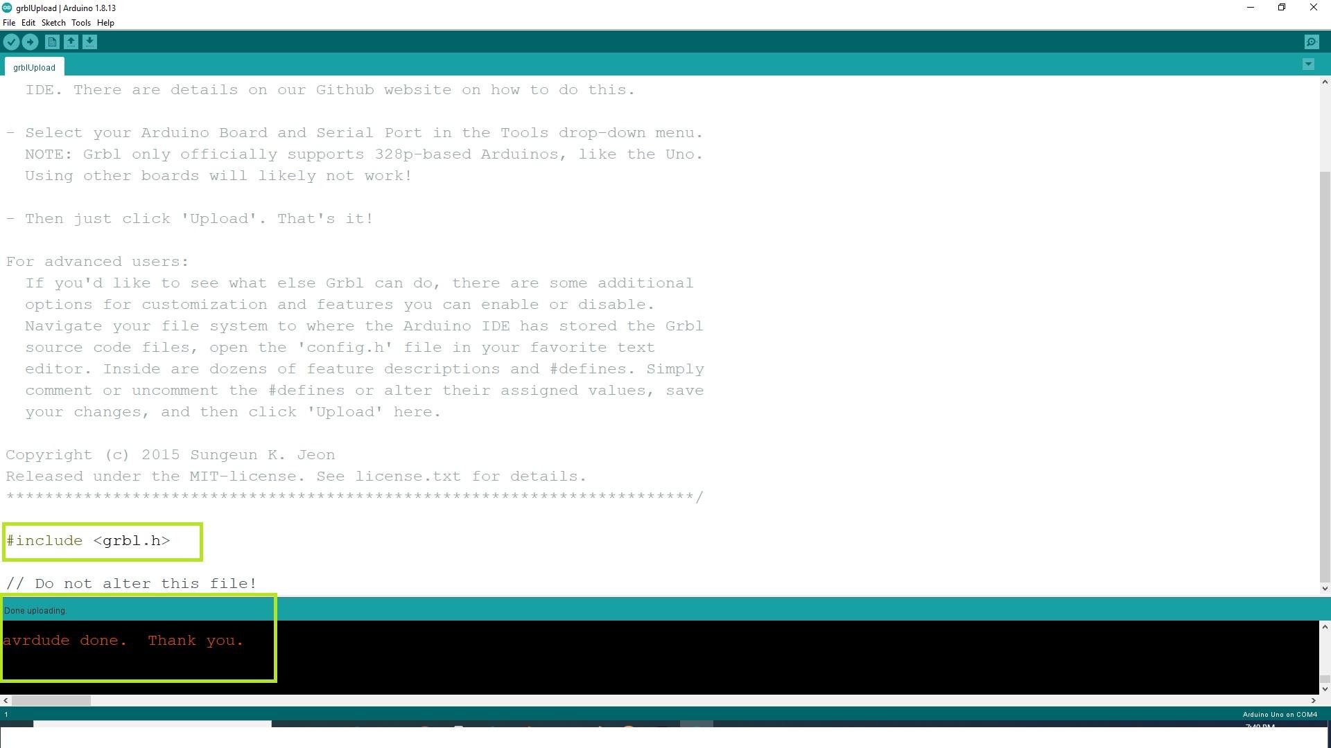
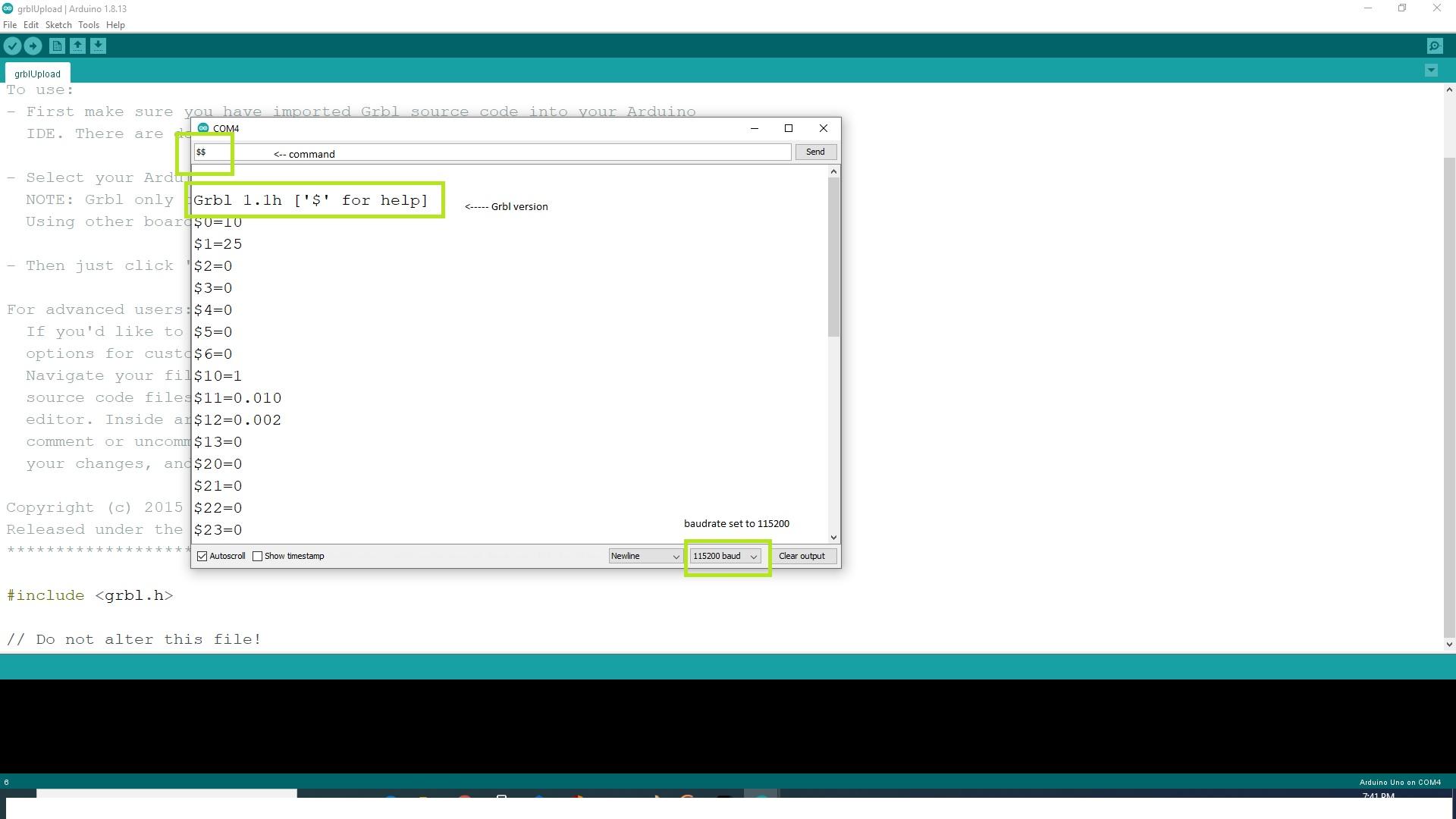
Uploading the firmware to the arduino, tells arduino how to move, take action etc..
And this helps to pass or convert the user image to the g-code and pass through the arduino. Arduino, according to the firmware help to generate steps/direction to the motor driver.
- Download the arduino IDE from here -> Arduino IDE v1.8.13
- Un-zip "grbl-1.1h.20190825v" the .zip file --> Grbl v1.1h
- copy the grbl folder to -->
- "C:\Users\vish\Documents\Arduino\libraries"
- close all the window and refresh it.
- open the arduino IDE
- Connect the data cable to the arduino from PC\laptop
- Choose the correct COM Port.
- Click upload.
- You will get an success message "Done uploding",
- if not showing, press CTRL+, Select the ◉compilation and ◉upload option, check for the message again.
- press CTRL+Shift+M, it opens the arduino serial monitor.
- change the baud rate to 115200.
- Type $$ and press ↵Enter.
- There displays the version of GRBL and its default settings.
- If you done all the above steps..
- You had successfully uploaded the firmware to the arduino.
Creating Custom G-code

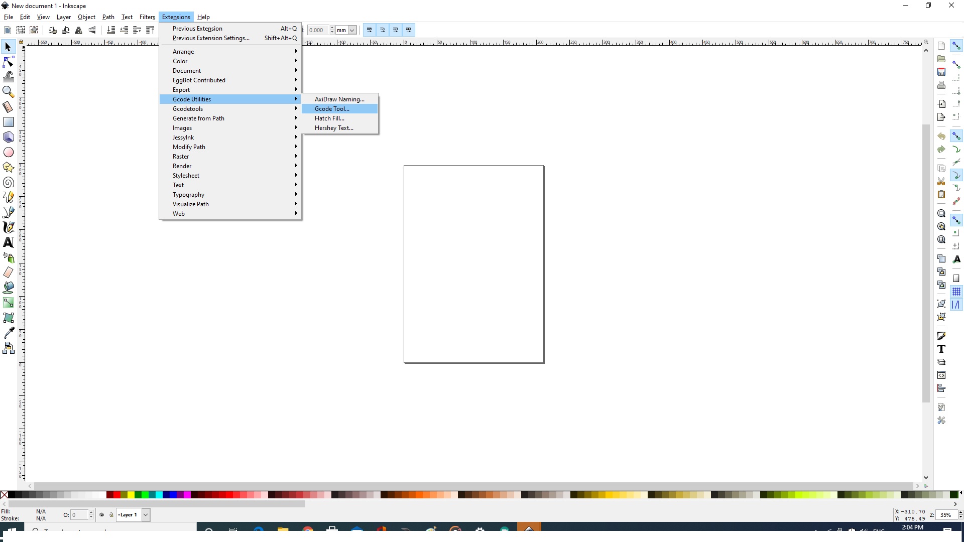
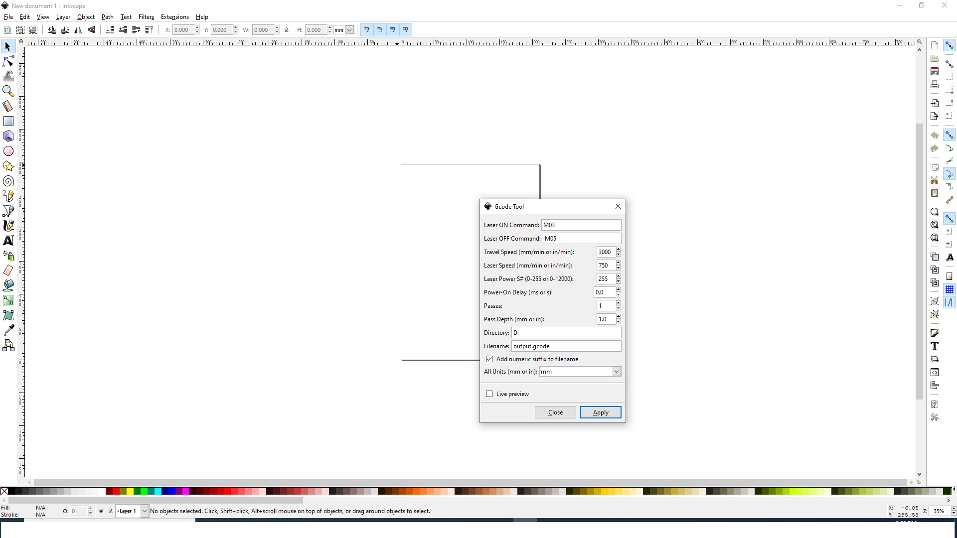
Watch the above video to know how to generate custom g-codes.
- Copy all the items from "inkscape extensions" and paste it to path
- Right click the inkscape application, Select "open file location", Select "share" folder, Select "extension folder", paste all those item to that folder.
- refresh it
- open inkscape v0.92
- You can find those added extension at inkscape's extension sub menu
- Draw your own SVG's.
- click G-code utilities, Select MI G-code option.
- you can find another window allowing you to generate G-code file and export to your choice location.
Download grbl Z-Axis servo controller here ->
Downloads
Working With G-code Sender/simulator
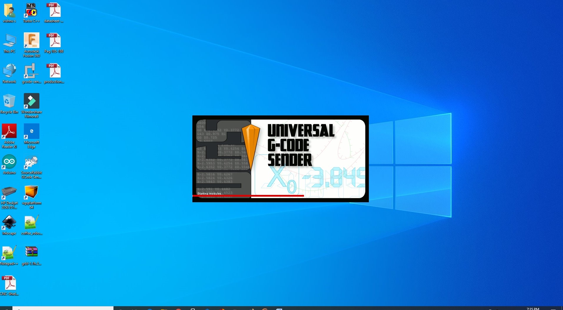
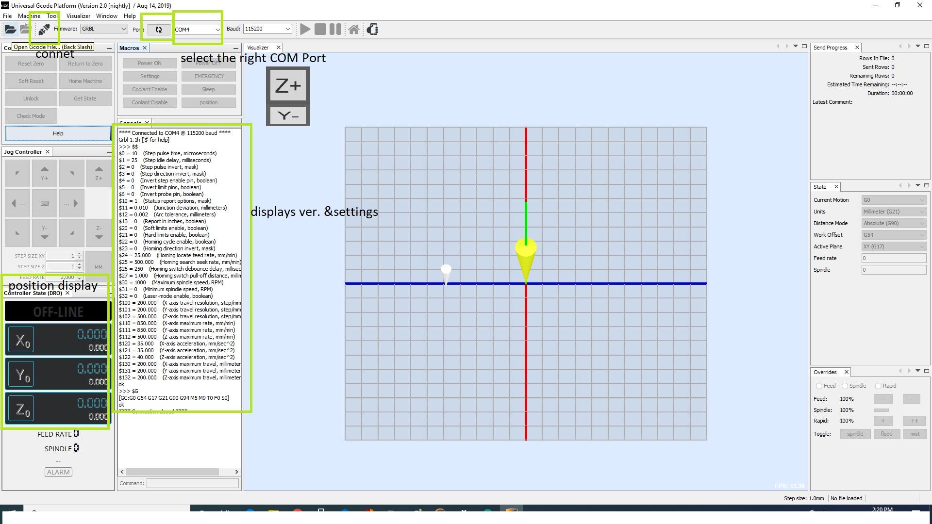
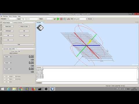
This session helps you to understand, how to use UGS - Universal G-code Sender
Its simple.... Universal g-code sender helps to send the g-code which is already created using inkscape.
- Open UGS
- Make sure that you had plugged in the arduino
- Select the appropriate COM Port
- Press "connect" button.
- Select "open" option above the bar
- choose your location where u have already exported your custom g-code files
- Press "OK"
- Now you can see the 3D simulation of you drawing.
- Make sure all the axis are in position, be ready to turn the main power supply in case of any emergencies like crashing the axis, short circuits etc...
Setting Machine for First Run
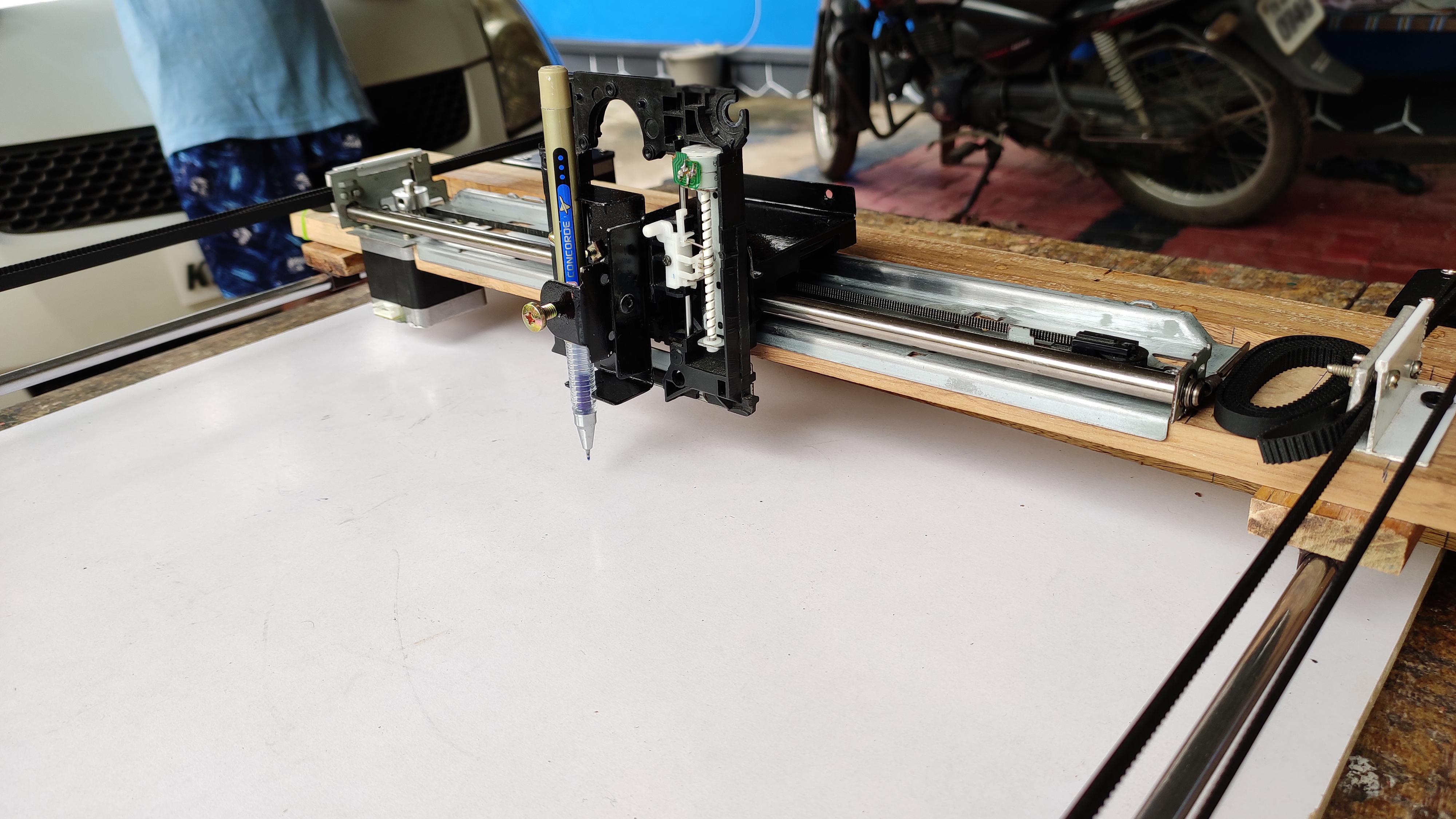
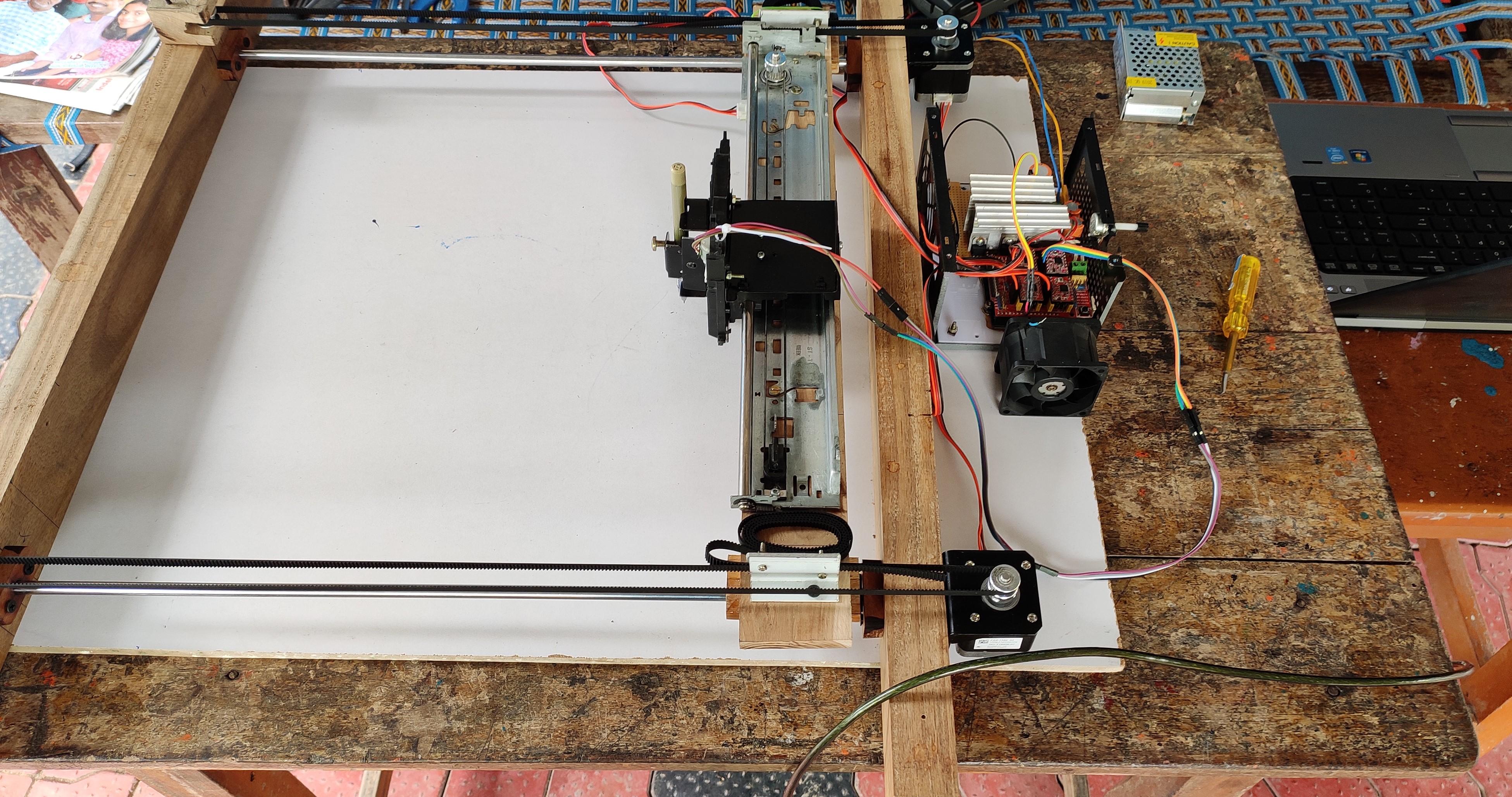
OK! all done :)
Now we are going to start the machine.
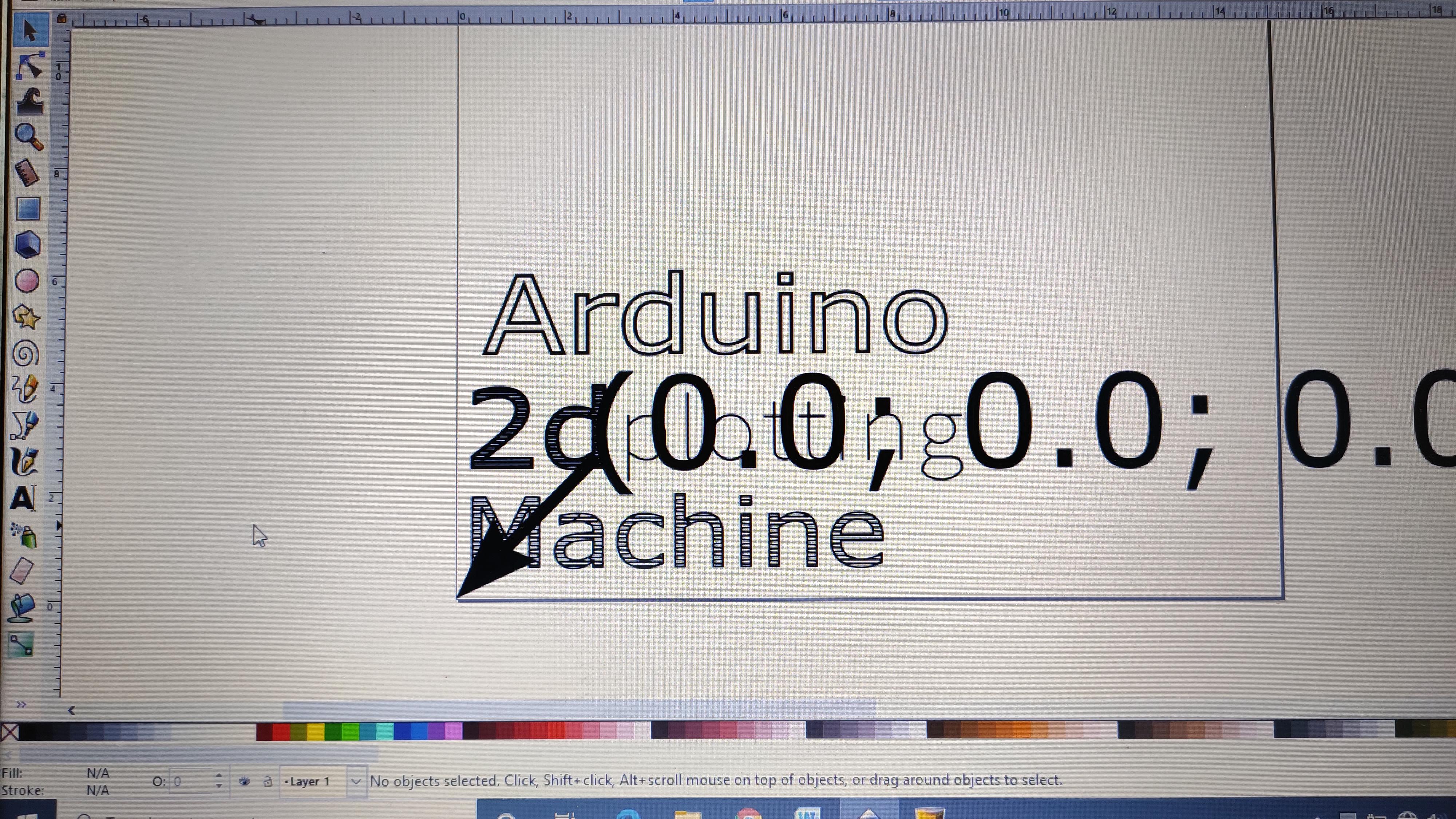
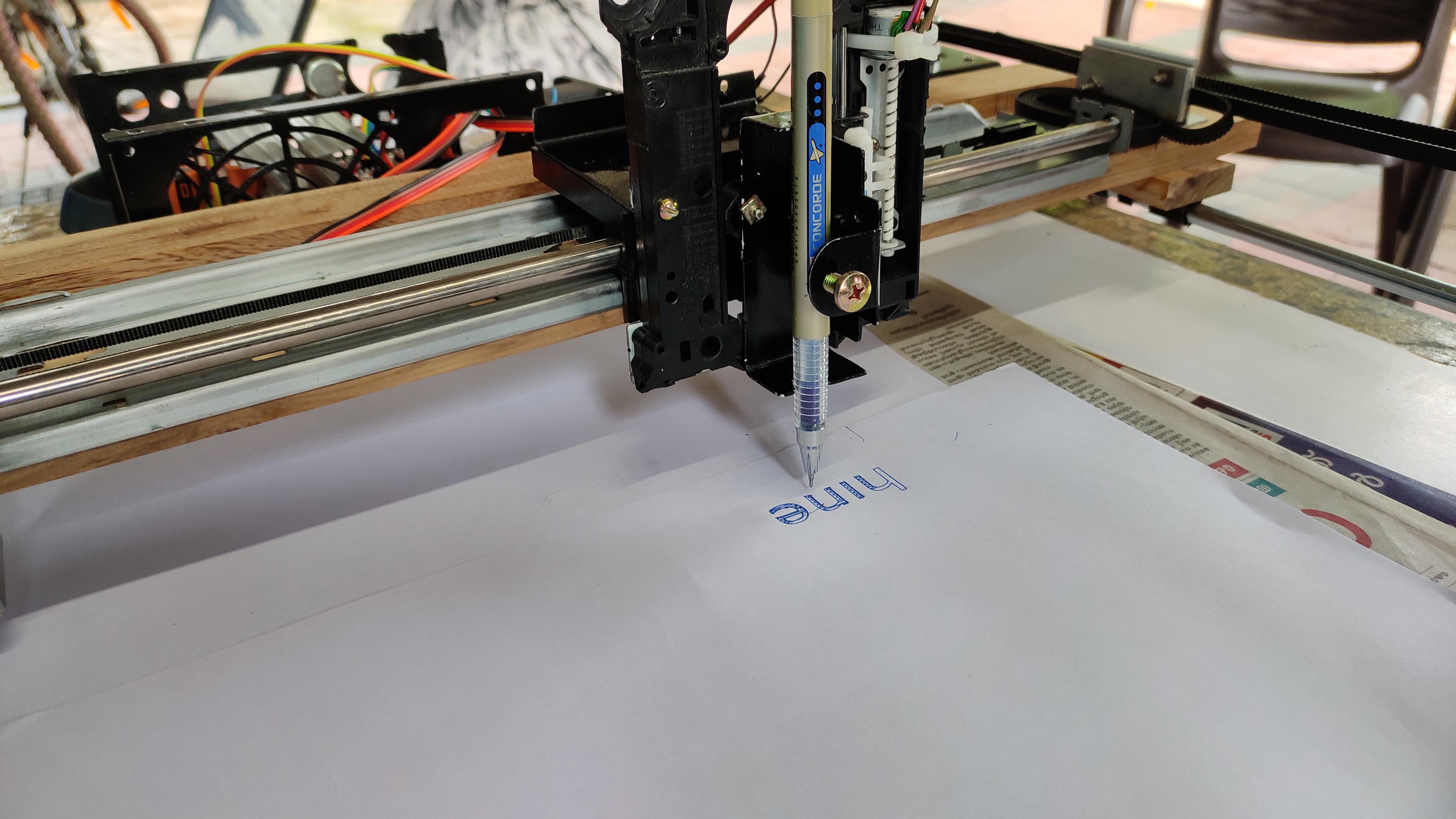
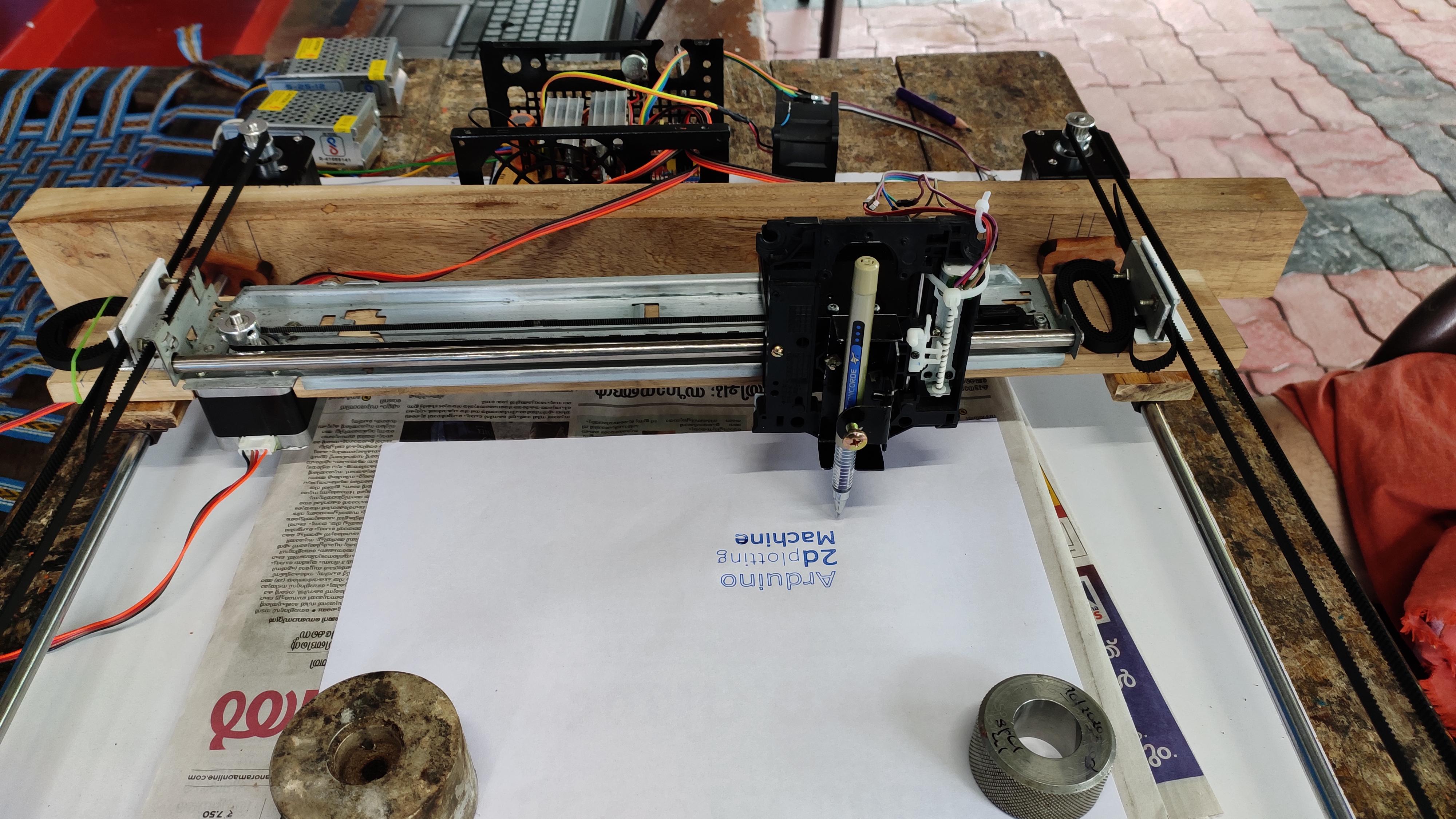
Here i have created text "Arduino" in double stroke and text "2d" with in hatch fill, the text "plotting" in single stroke and finally the text "machine" with hatch fill with some gaps in it.
To do so....
- Open inkscape create the text or of your own, and then click "object to path" option from the sub menu.
- After that open the Servo axis supported g-code generator extension, while doing please make sure that the text which you need to generate should be selected.
- And change the settings as your convenience.
- Select export with the path mentioned.
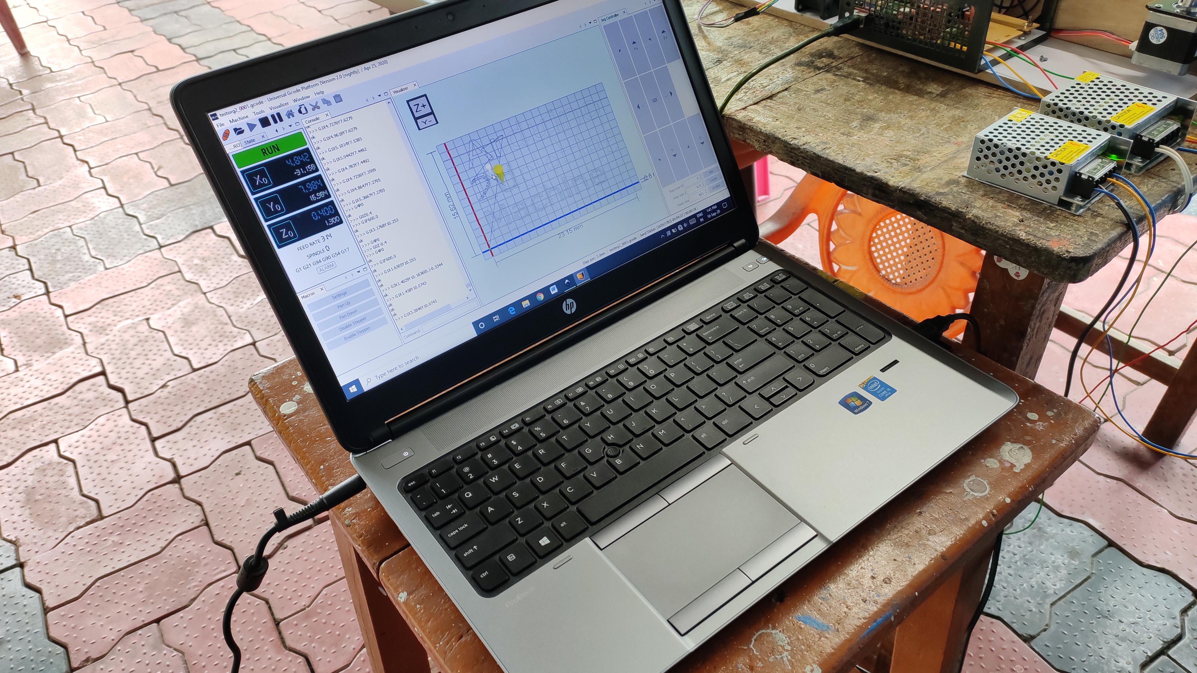
- Open the UGS software
- Connect to the machine
- Check for the position
- Import the g-code file which you created.
- Select 'send' button.
- As you can see your machine started moving.
NB: If you are using a stepper motor instead of servo for Z-axis, rewrite "G0 Z0.4" for raising the pen up and "G0 Z-0.4" for lowering the pen in G-code generator extension window. Keep in mind you can put *['G0 Z ±xx' ]value according to your z-axis safe height in place of *xx
Final Result:
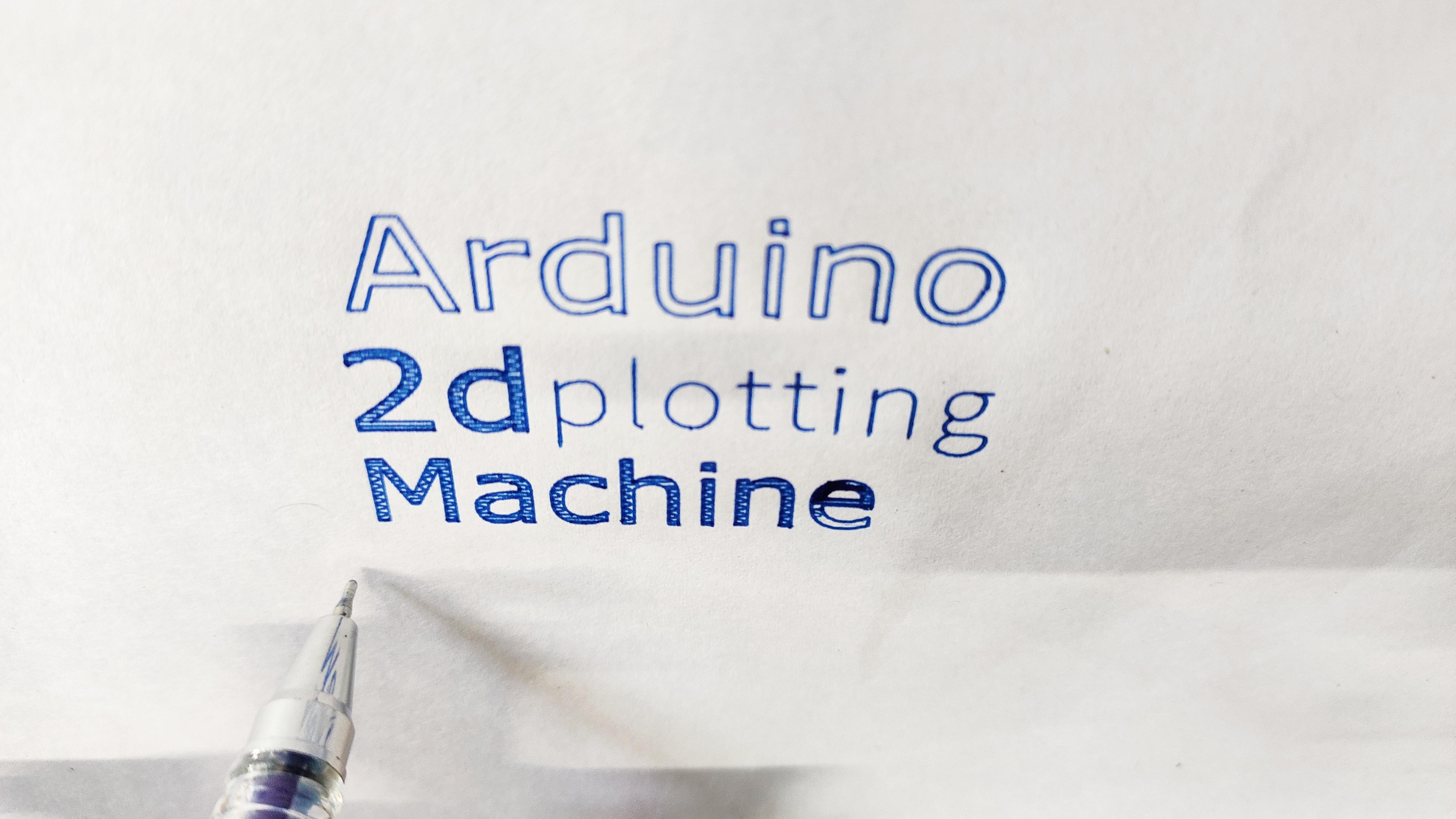

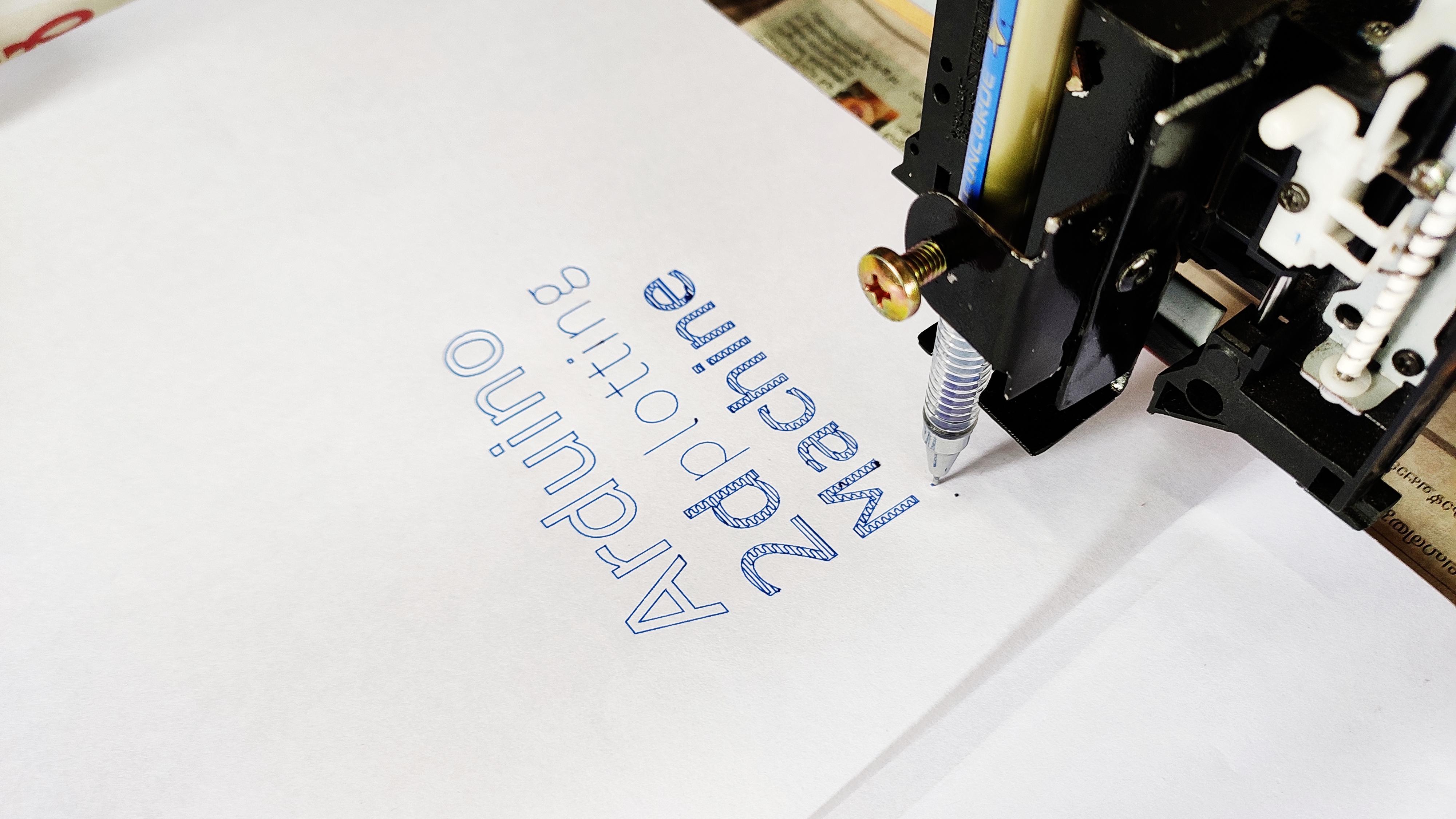
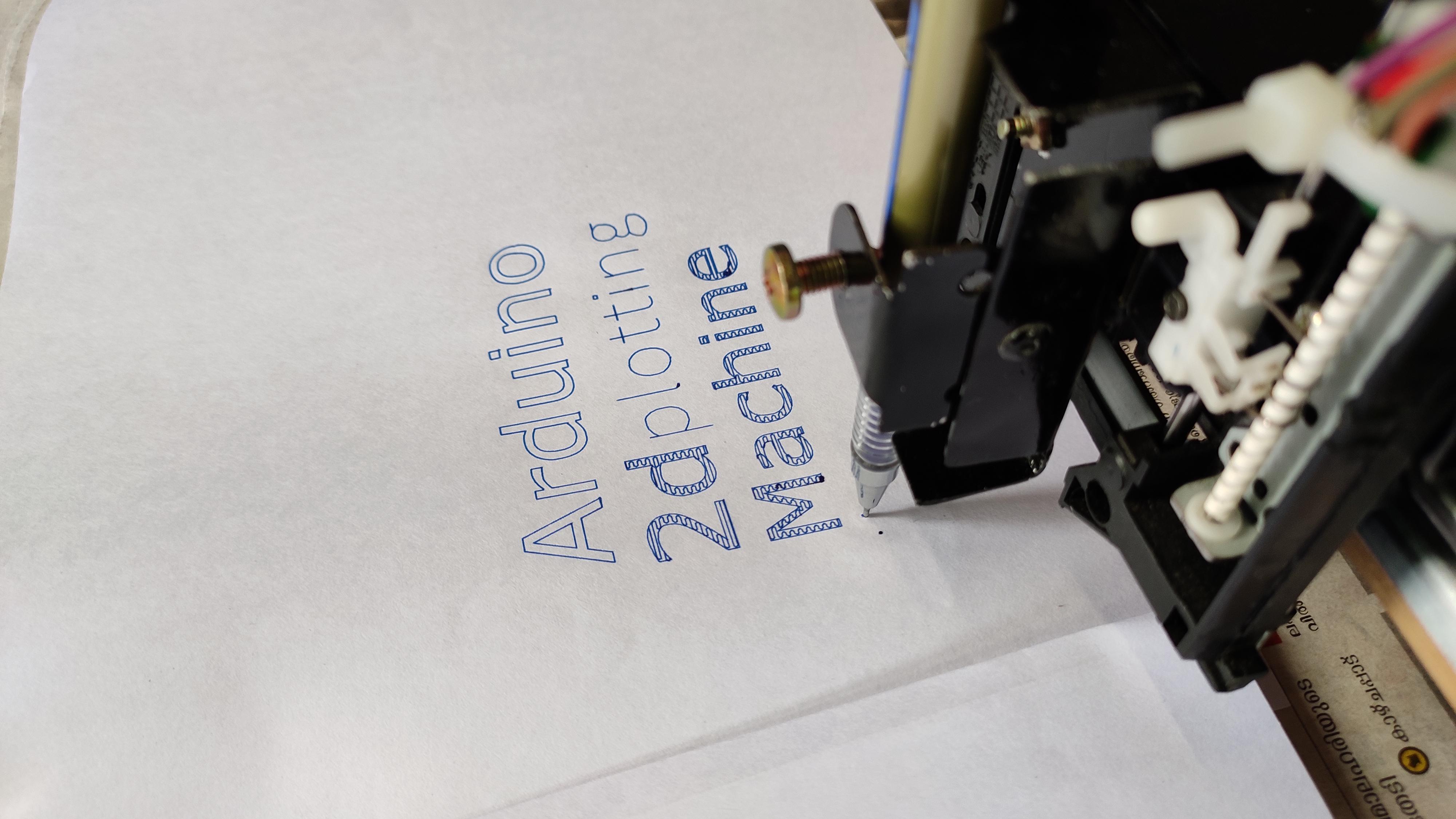

So all ended good :)
These above images shows the result of my 2D drawing machine.
If you had reached here by reading all my steps, thank you
cu next time.
~ vishnu sukumar