TfCD - Plus


Plus is a minimal smart light, which not only notify people about the weather condition, but also create an enjoyable experience for users by the changes made in the colour of light by rotating the plus. It's shape gives user the opportunity to combine several plus modules or create a huge lamp with lots of plus pieces placed by friends. This lighting project is a part of Advanced Concept Design(ACD) course at TU Delft university, and the technology implemented by using TfCD practical as a source of inspiration.
Ingredients
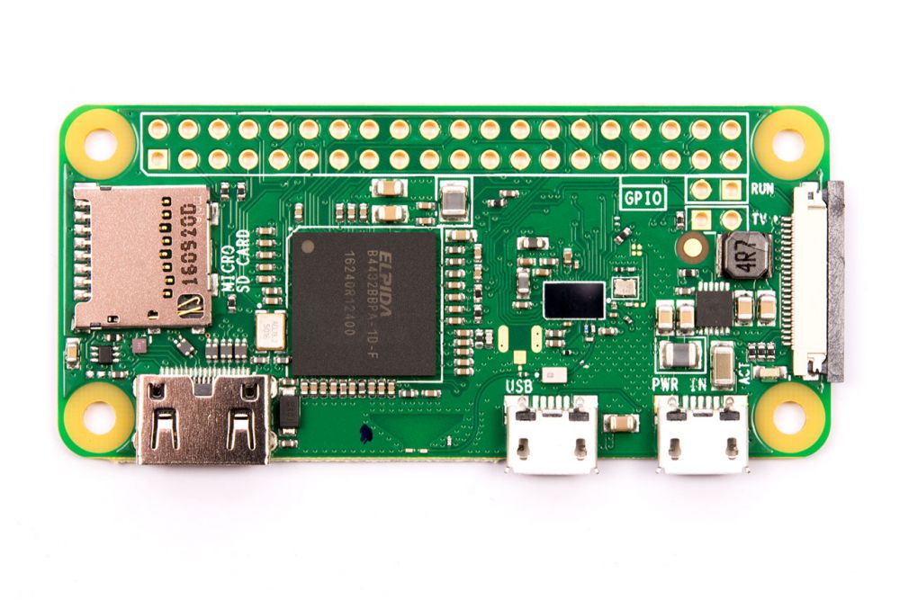


1 Raspberry pi zero w
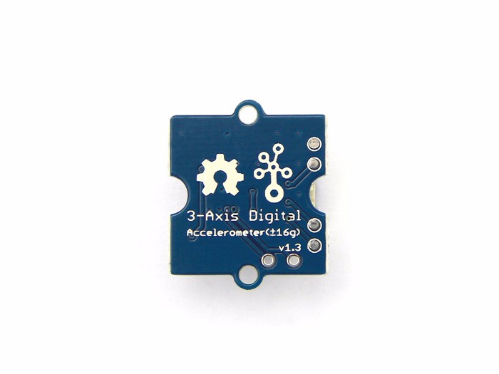
1 Groove Adxl345 accelerometer
4 Ws2812b LED
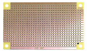
1 Prototyping board
3D printed and laser-cut enclosures
Hardware
LEDs
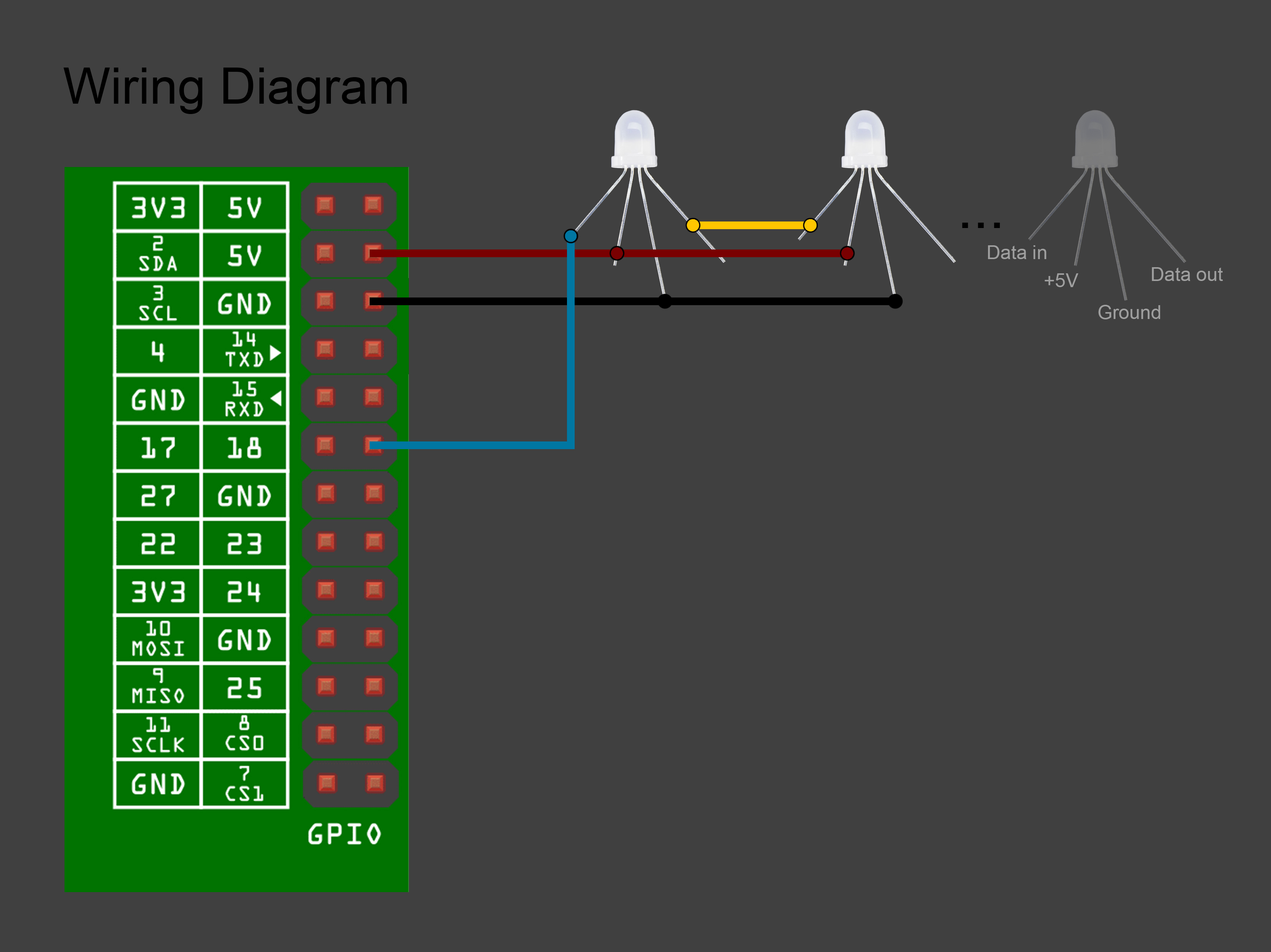
The Neopixel LEDs have 4 pins named: +5V, GND, Data In and Data out.
- Pin 4 of the raspberry pi is connected to the +5V of all LEDs
- Pin 6 of the raspberry pi is connected to the GND of all LEDS
- Data In pin of the first LED is connected to pin 12 on the raspberry pi.
- The Data out pin of the first LED is connected to the Data in of the second and so forth.
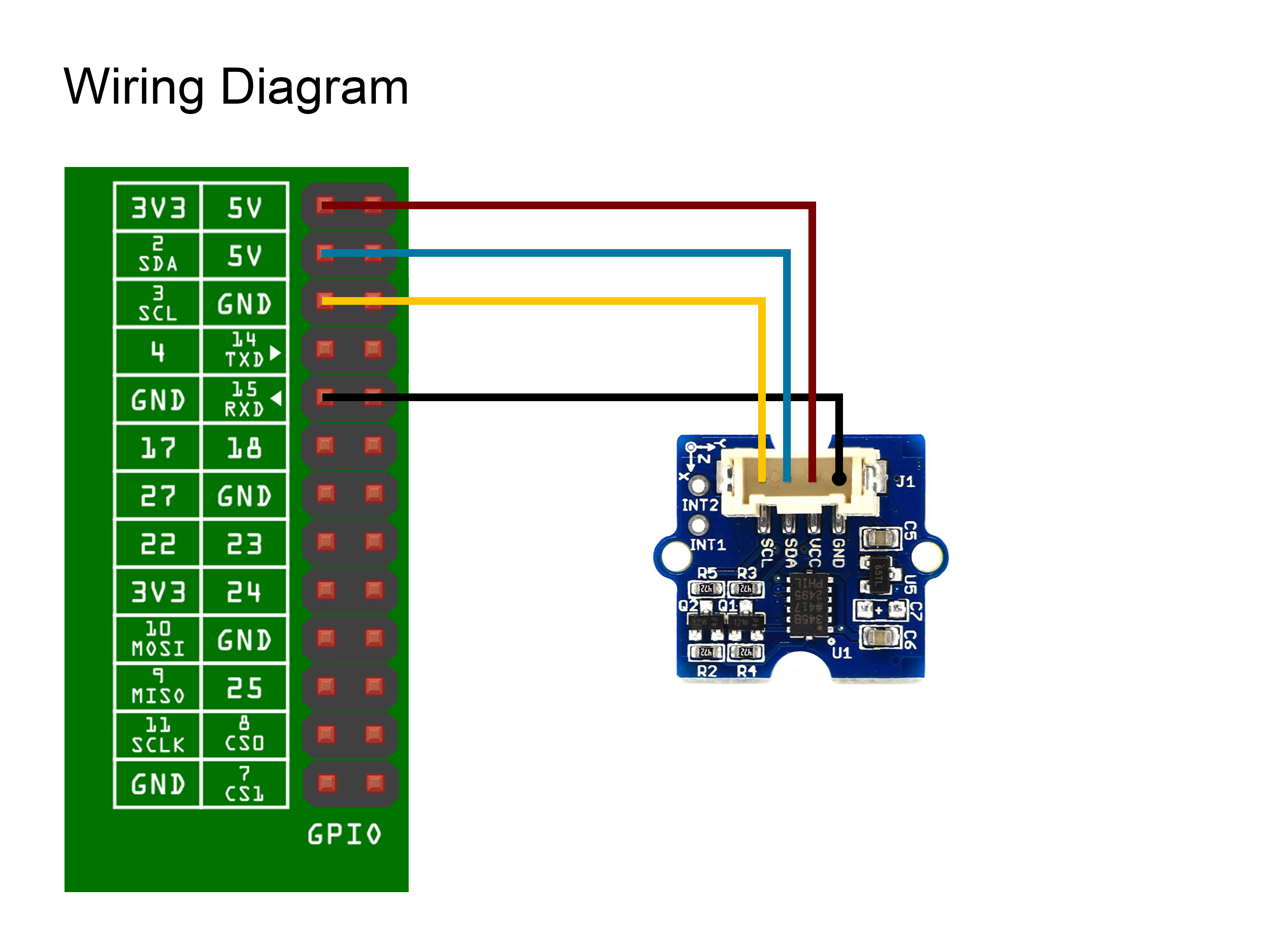
Please have a look at the wiring diagram for a better understanding.
Accelerometer
The accelerometer has 4 pins named: VCC, GND, SDA and SCL.
- Pin 1 of the raspberry pi is connected to VCC.
- Pin 3 of the raspberry pi is connected to SCL.
- Pin 5 of the raspberry pi is connected to SDA.
- Pin 9 of the raspberry pi is connected to GND.
Build
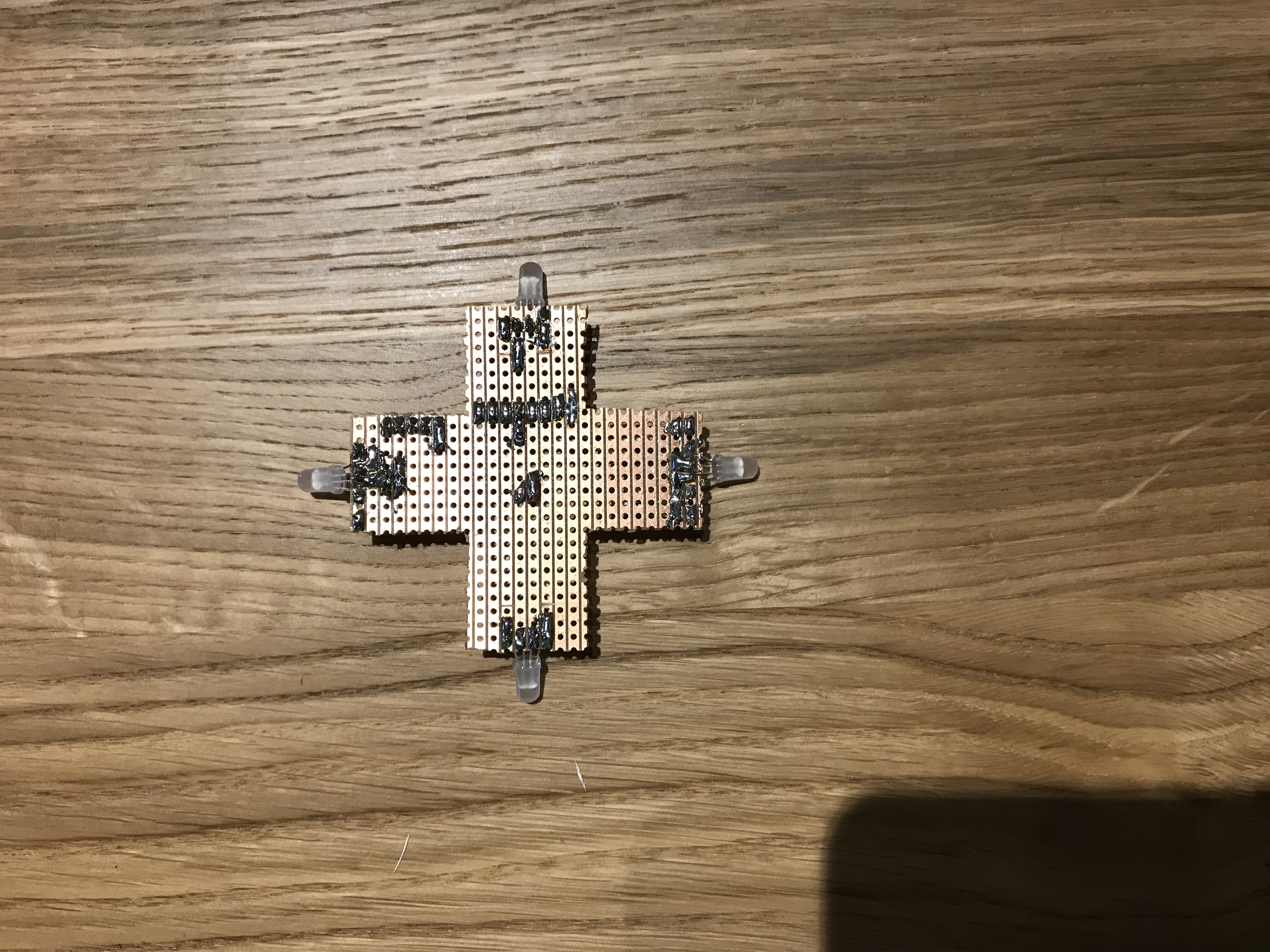
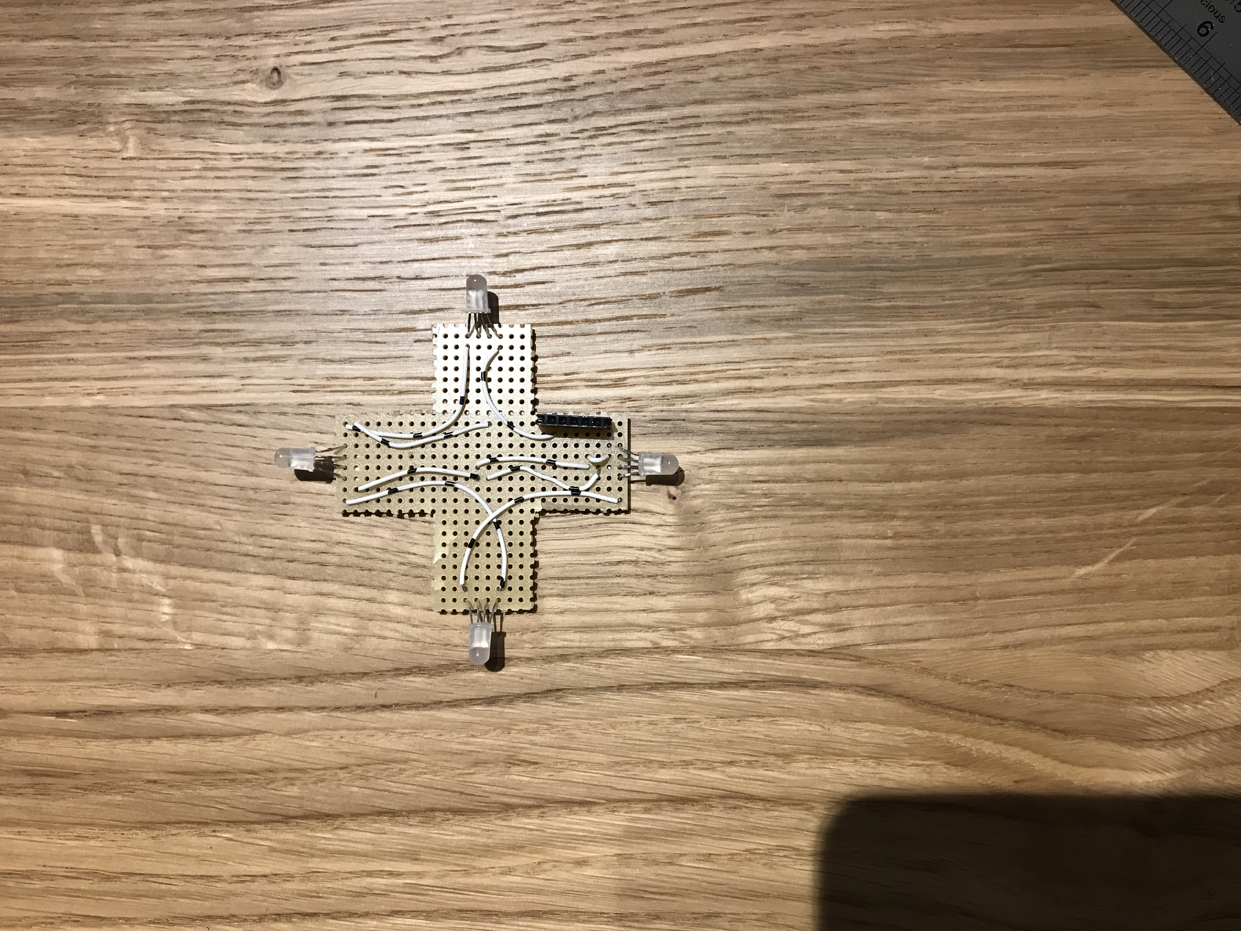
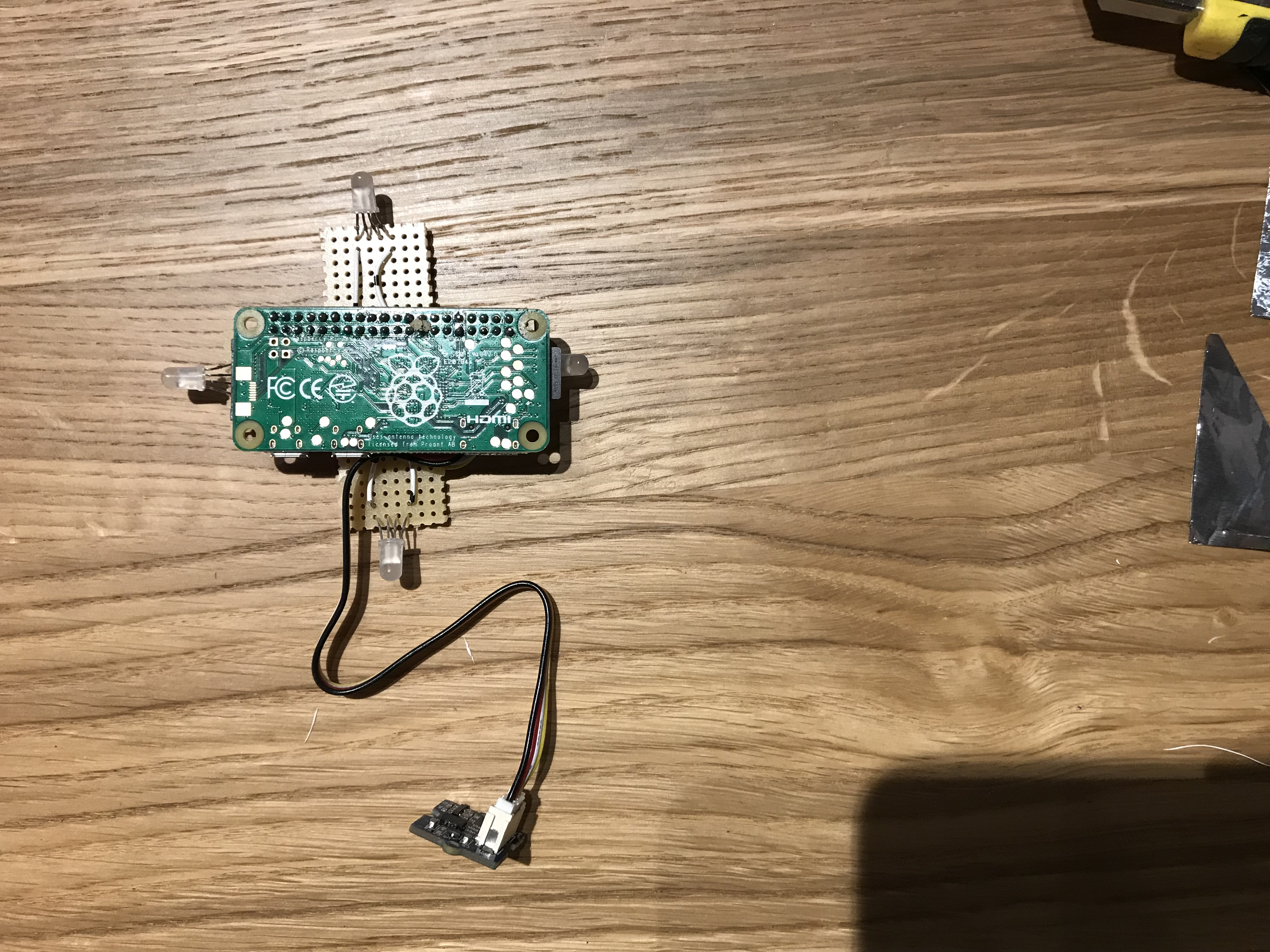
- For convenience, the LEDs can be soldered onto a prototyping board. We have decided to cut the board into the shape of a plus so that it fits well within the 3D designed case.
- Once we have soldered the LEDs on the board, we solder jumper wires to make the connections between a 0.1" header connect and the LEDs. The header connector is used to alow the raspberry pi to be disconnected and re-used for a future project.
Software
We first need to get the Raspberry Pi up and running. To do this we follow these steps:
- Download the latest version of Raspbian from here. You can download it directly or via the torrents.You will be needing an image writer to write the downloaded OS into the SD card (micro SD card in case of Raspberry Pi B+ model and Raspberry Pi Zero).
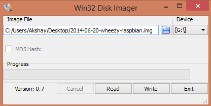
- So download the "win32 disk imager" from here. Insert the SD card into the laptop/pc and run the image writer. Once open, browse and select the downloaded Raspbian image file. Select the correct device, that is the drive representing the SD card. If the drive (or device) selected is different from the SD card then the other selected drive will become corrupted. SO be careful.
- After that, click on the "Write" button in the bottom. As an example, see the image below, where the SD card (or micro SD) drive is represented by the letter "G:\" The OS is now ready for normal usage. However in this tutorial we are going to use the Raspberry Pi in headless mode. This means without a physical monitor and keyboard attached to it!
- After burning the SD card, do not eject it from your computer! Use a text editor to open up the config.txt file that is in the SD card. Go to the bottom and add dtoverlay=dwc2as the last line:
- Save the config.txt file as plain text and then open up cmdline.txt After rootwait (the last word on the first line) add a space and then modules-load=dwc2,g_ether.
- Now remove the SD card from your PC and insert it into the Raspberry Pi and connect it to your PC using a USB cable. Once the OS has booted up, you should see a new Ethernet Gadget device being discovered.
- You can use ssh pi@raspberrypi.local to connect to the board and control it remotely.For more detailed instructions regarding headless operation go here.Neopixel Driver
The rpi_ws281x library is the key that makes using NeoPixels with the Raspberry Pi possible.
First we need to install the tools needed to compile the library. In your Raspberry Pi run: sudo apt-get update && sudo apt-get install build-essential python-dev git scons swig Now run these commands to download and compile the library:
git clone https://github.com/jgarff/rpi_ws281x.git && cd rpi_ws281x && scons Finally, after the library was successfully compiled, we can install it for python using:
cd python && sudo python setup.py install Now comes the python code that drives the LEDs. The code is fairly simple with some comments to help you out. from neopixel import * # NeoPixel configurations LED_PIN = 18 # Raspberry Pi's GPIO pin connected to the pixels LED_BRIGHTNESS = 255 # Set to 0 for darkest and 255 for brightest LED_COUNT = 4 # Number of LED pixels strip = Adafruit_NeoPixel(LED_COUNT, LED_PIN, 800000, 5, False, LED_BRIGHTNESS, 0, ws.WS2811_STRIP_GRB) # Initialize the library strip.begin() strip.setPixelColor(0, Color(255, 255, 255)) strip.show()
ADXL345 Driver
The accelerometer sensor that we have selected has an I2C interfae for communicating with the outside world. Fortunately for us, the Raspberry Pi also has I2C interface. We just need to enable it to use it in our own code.
Call the Raspbian configuration tool using sudo raspi-config. Once running, go to Interfacing Options, Advanced Options and then enable I2C.Install the relevant python modules so that we can use the I2C interface in python:
sudo apt-get install python-smbus i2c-tools The following python code allows us to communicate with the accelerometer sensor and the read its register values for our own purposes. import smbus import struct # Accelerometer configurations bus = smbus.SMBus(1) address = 0x53 gain = 3.9e-3 bus.write_byte_data(address, 45, 0x00) # Go to standby mode bus.write_byte_data(address, 44, 0x06) # Bandwidth 6.5Hz bus.write_byte_data(address, 45, 0x08) # Go to measurement mode # Read data from the sensor buf = bus.read_i2c_block_data(address, 50, 6) # Unpack the data from int16_t to python integer data = struct.unpack_from(">hhh", buffer(bytearray(buf)), 0)
x = float(data[0]) * gain
y = float(data[1]) * gain
z = float(data[2]) * gain
Movement Detector
One of the feature of the light we are making, is that it can detect movement (or lack there of) to enter interactive mode (where the light changes based on rotation) and weather forecast mode (where the light changes depending on the weather forecast for today). The following code uses the previous function to read the acceleration values for the 3-axes and alert us when there is movement.
accel = getAcceleration()
dx = abs(prevAccel[0] - accel[0])
dy = abs(prevAccel[1] - accel[1])
dz = abs(prevAccel[2] - accel[2])
if dx > moveThreshold or dy To > moveThreshold or dz > moveThreshold:
print 'moved'
moved = True
else:
moved = False
Weather API
To receive weather forecast we can use Yahoo Weather. This involves talking to the Yahoo Weather Rest API which can be rather complex. Fortunately for us, the hard part is already taken care of in the form of the weather-api module for python.
- First we need to install this module using: sudo apt install python-pip && sudo pip install weather-api
- Please visit the author's website for more information about this module.
Once install the following code gets the weather condition for this moment
from weather import Weather
weather = Weather()
location = weather.lookup_by_location('dublin')
condition = location.condition()
print(condition.text())
Putting it all together
The entire code for the project which connects all of the above pieces can be found in here.
Auto starting the python script at boot time
To be able to put the raspberry pi into a box and have it run our code every time we connect it to the power, we must make sure that the code is automatically started during boot. To do this we use a tool called cron.
- First call the cron tool using: sudo crontab -e
- The previous steps will open up a configuration file, in which we add the following line:
@reboot python /home/pi/light.py &
Modelling and 3D Print
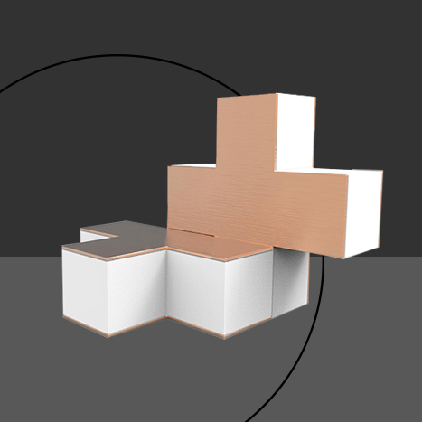

The 3D model of Plus has been made in Solidworks, and saved as .Stl format. Then for 3D printing the model, .Stl file were imported in the Cura software. Each side of the plus took 2:30 hrs to produce; so each full Plus took about 5 hrs to print. And for the transparent sides, plexiglass were laser-cut.
Downloads
Assembly
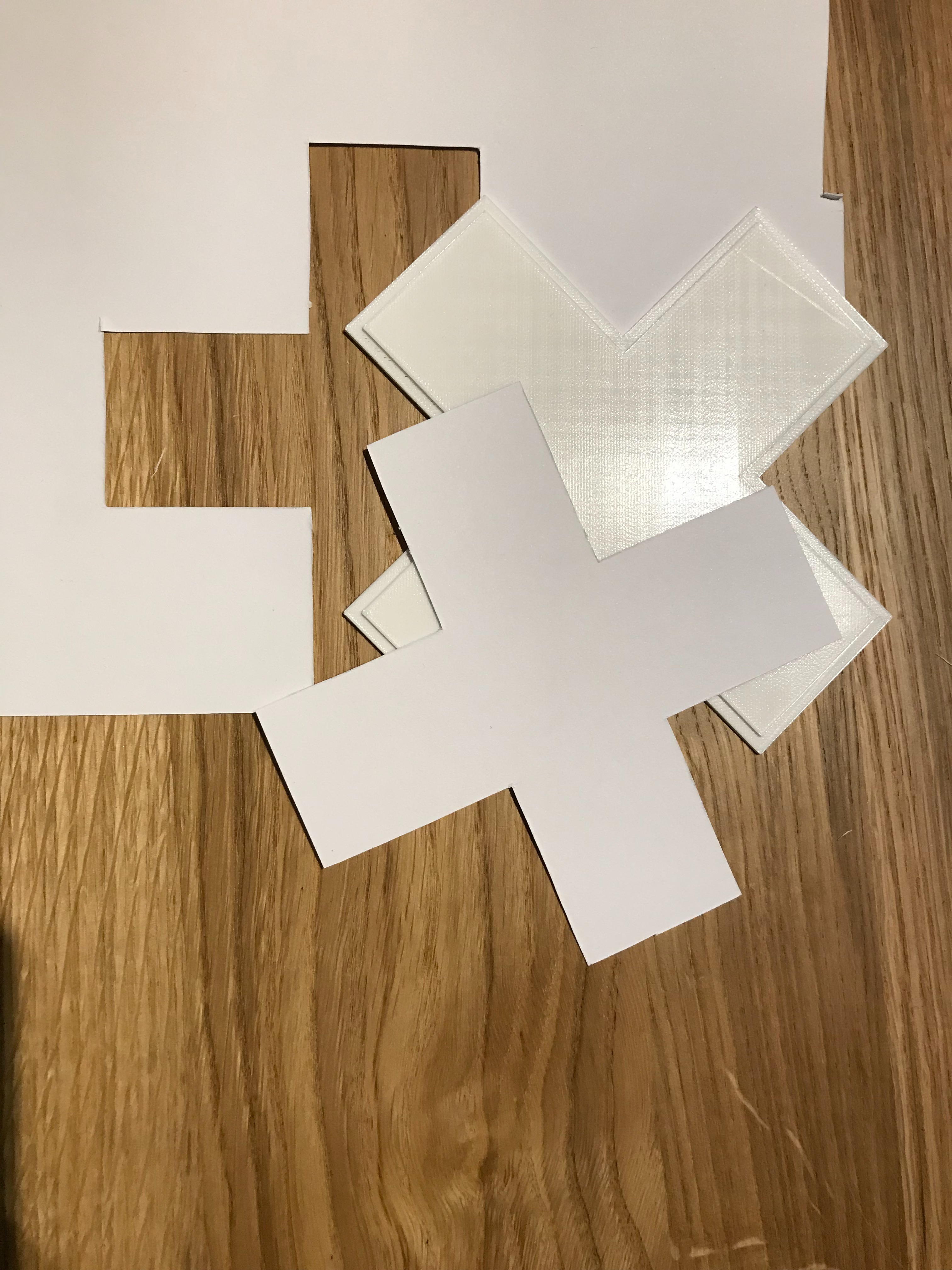
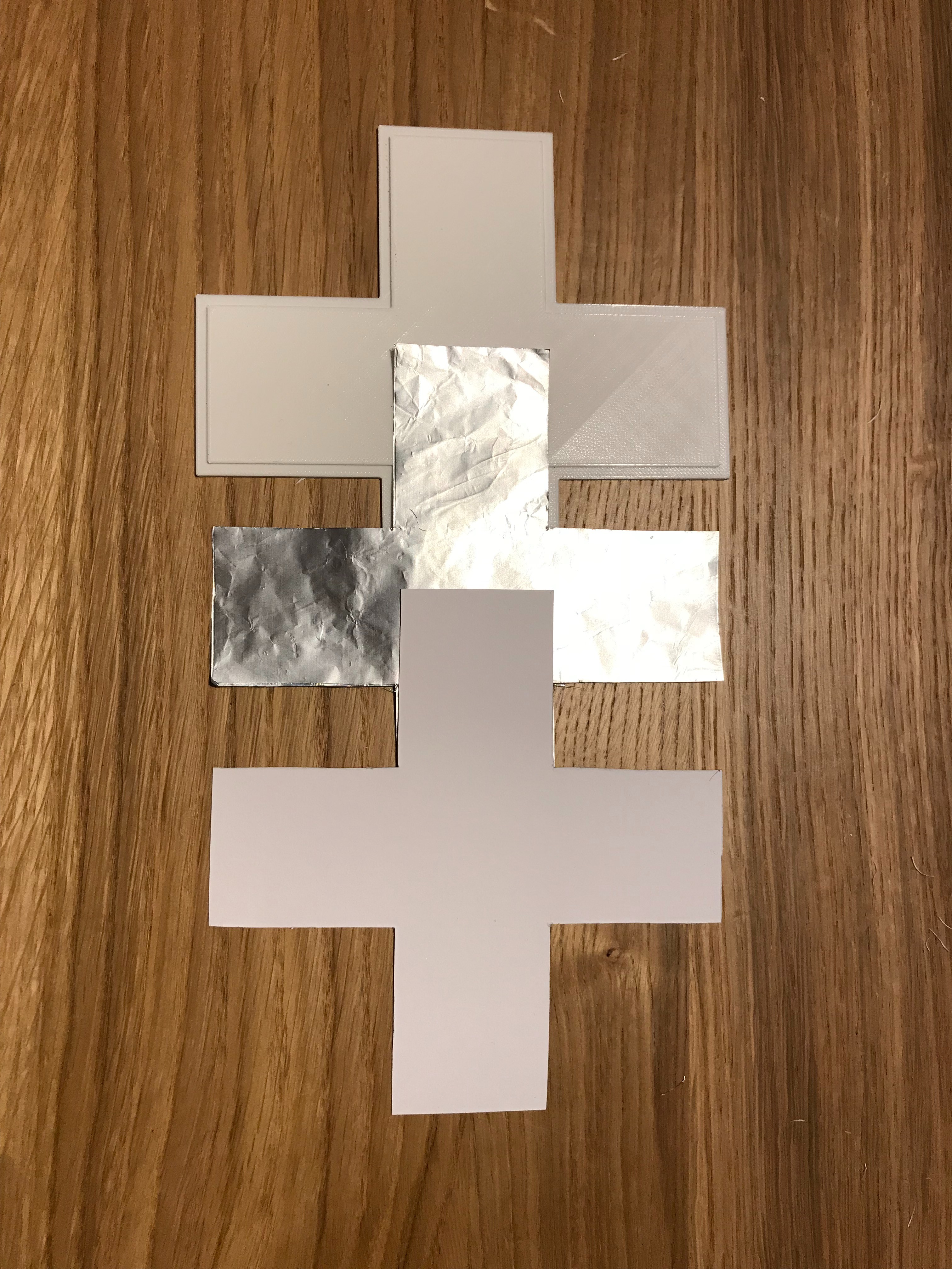
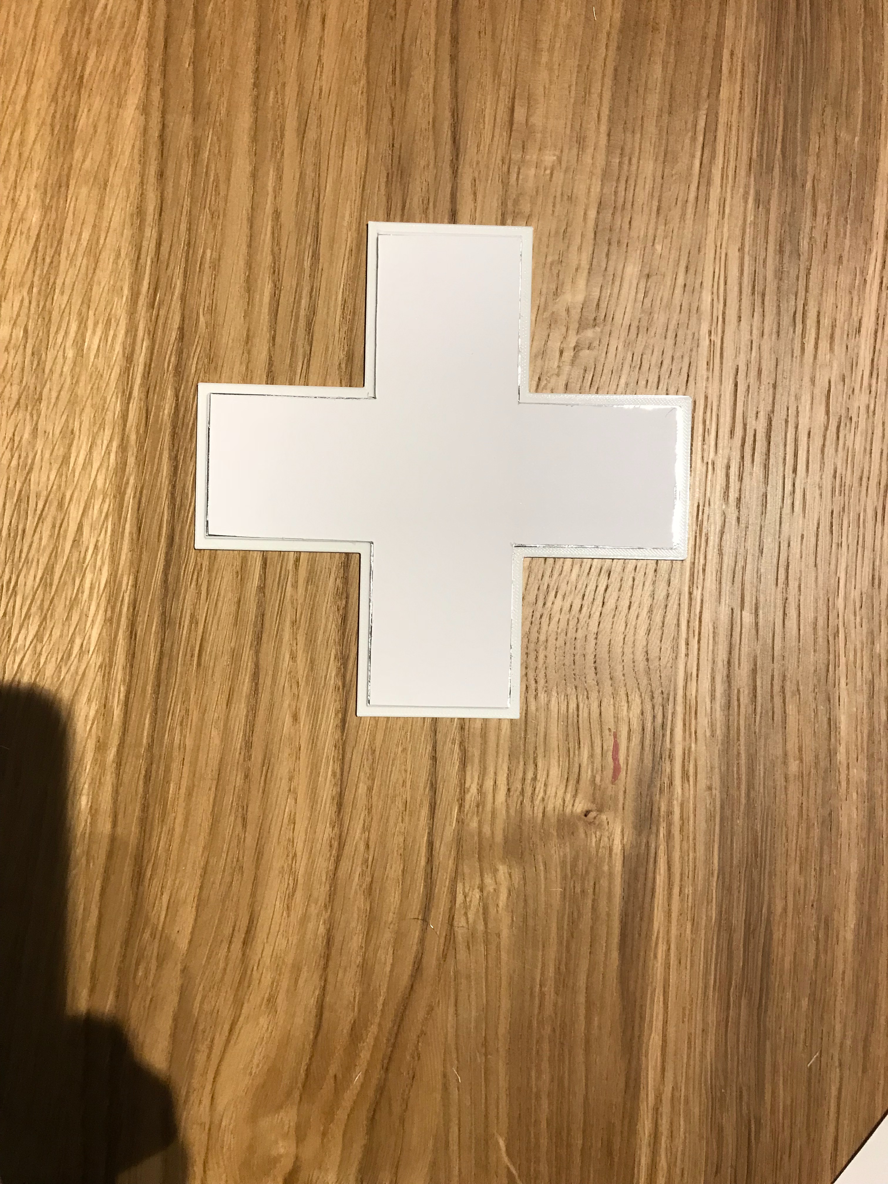
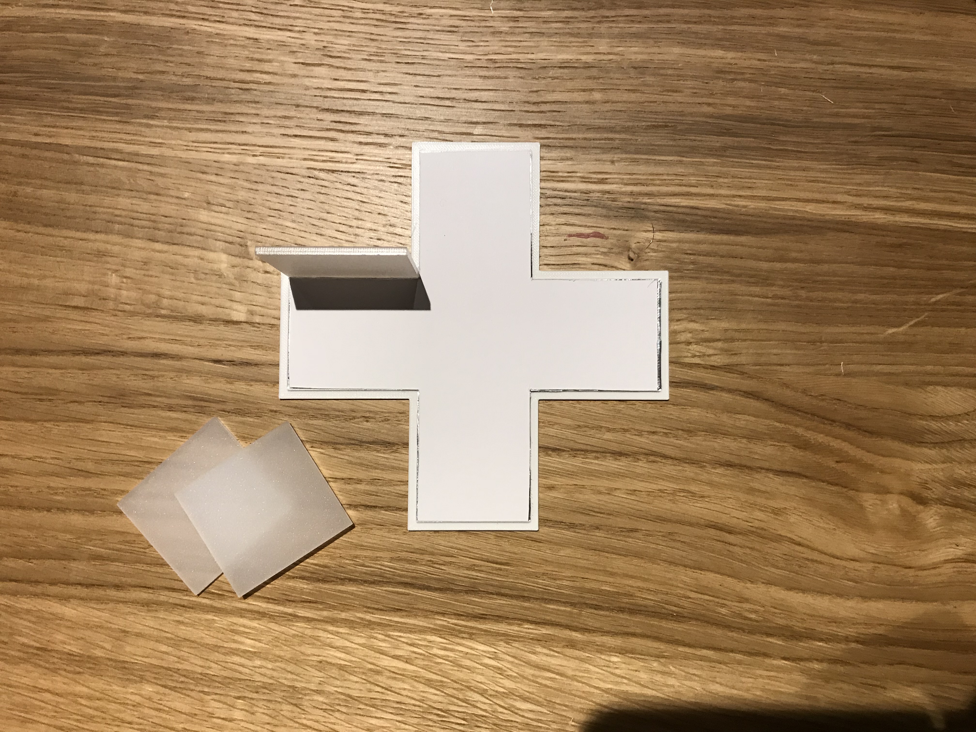
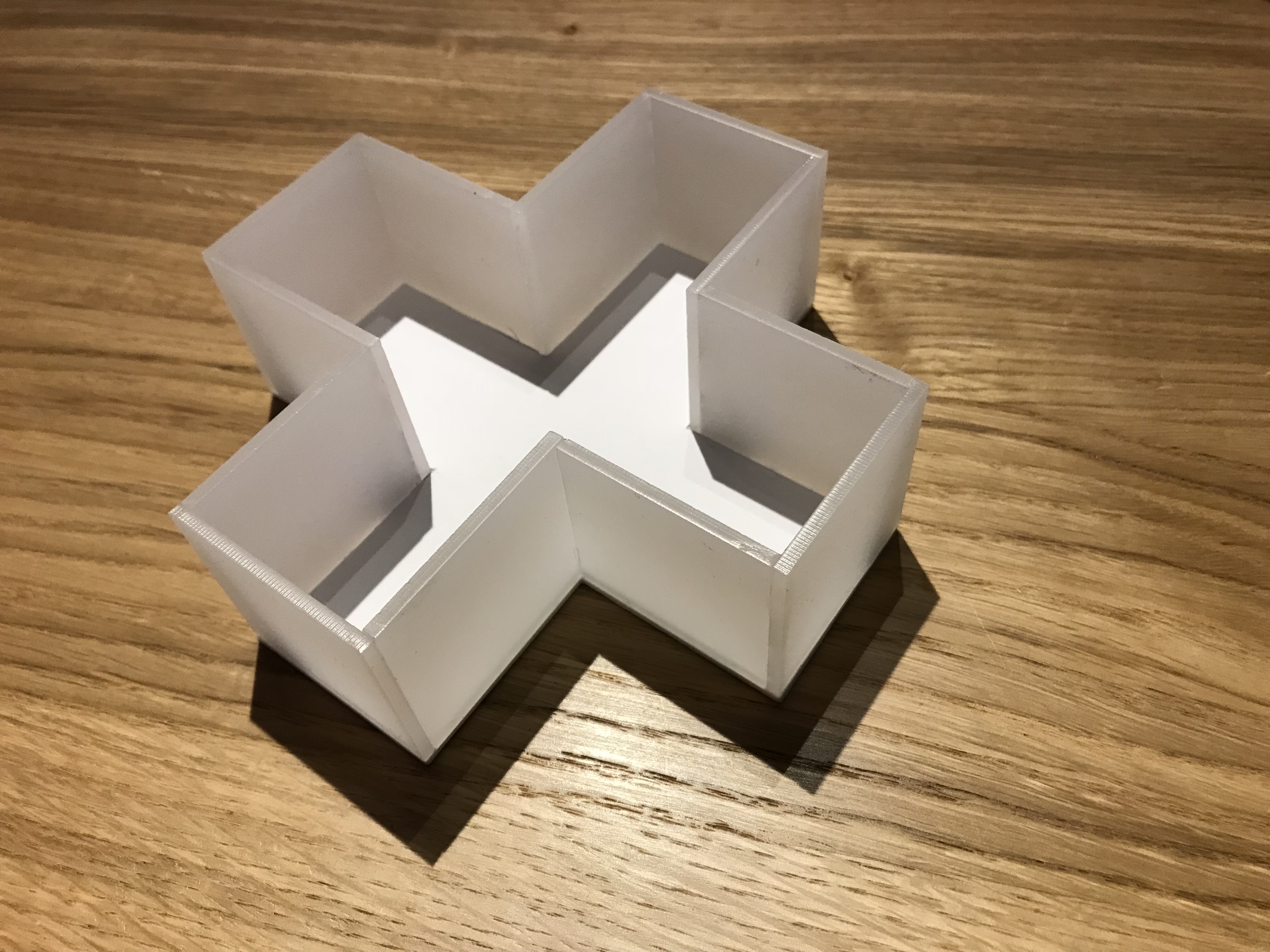
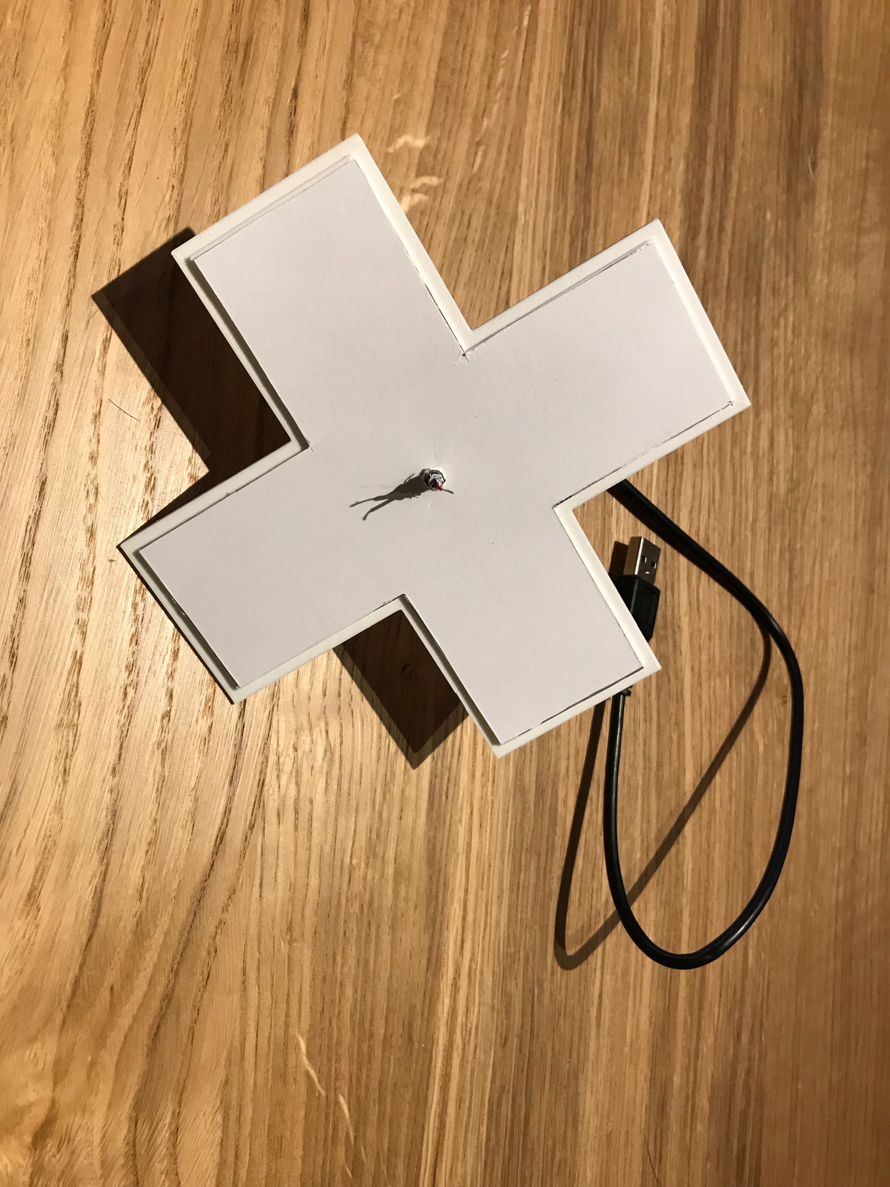
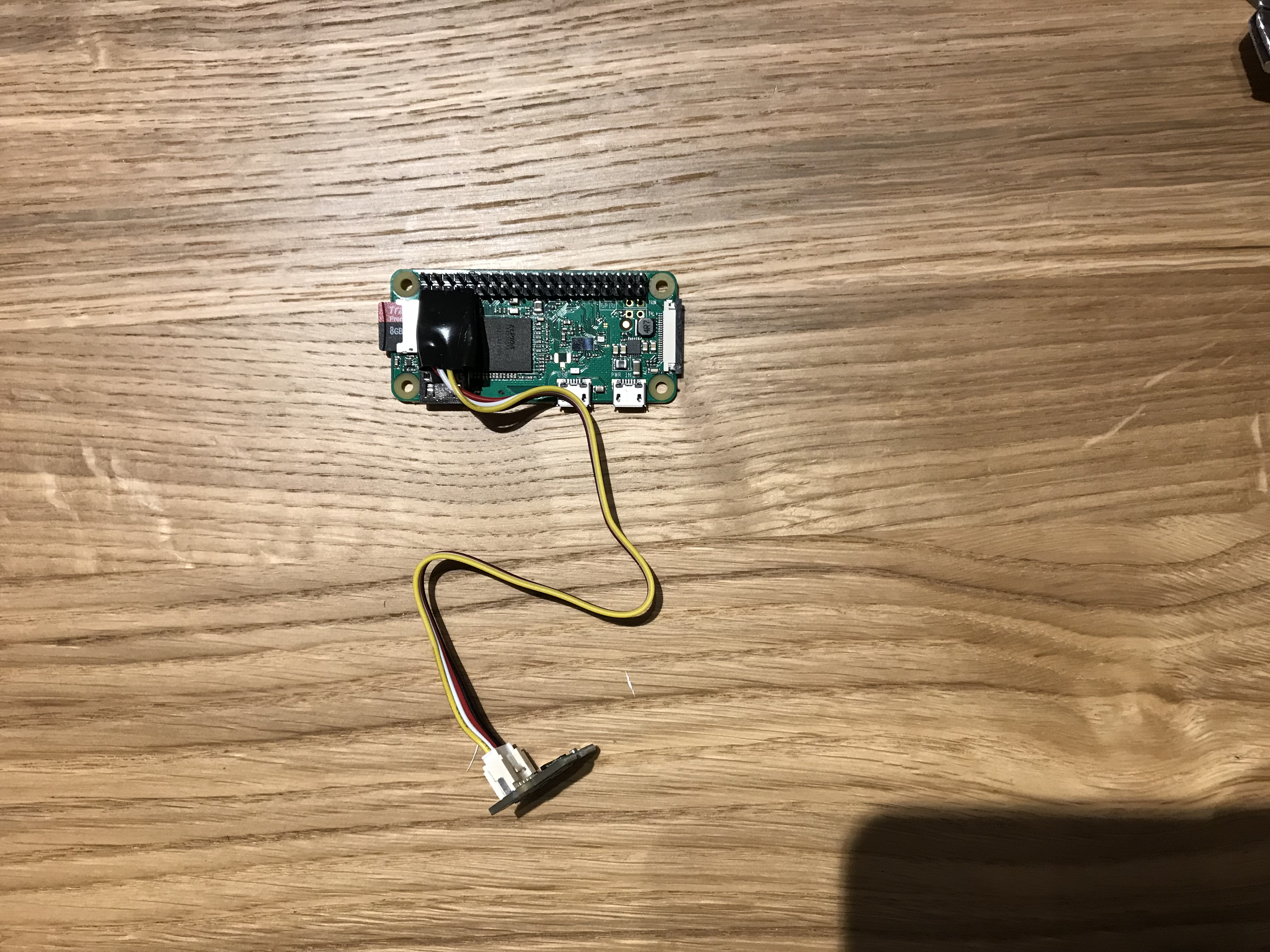
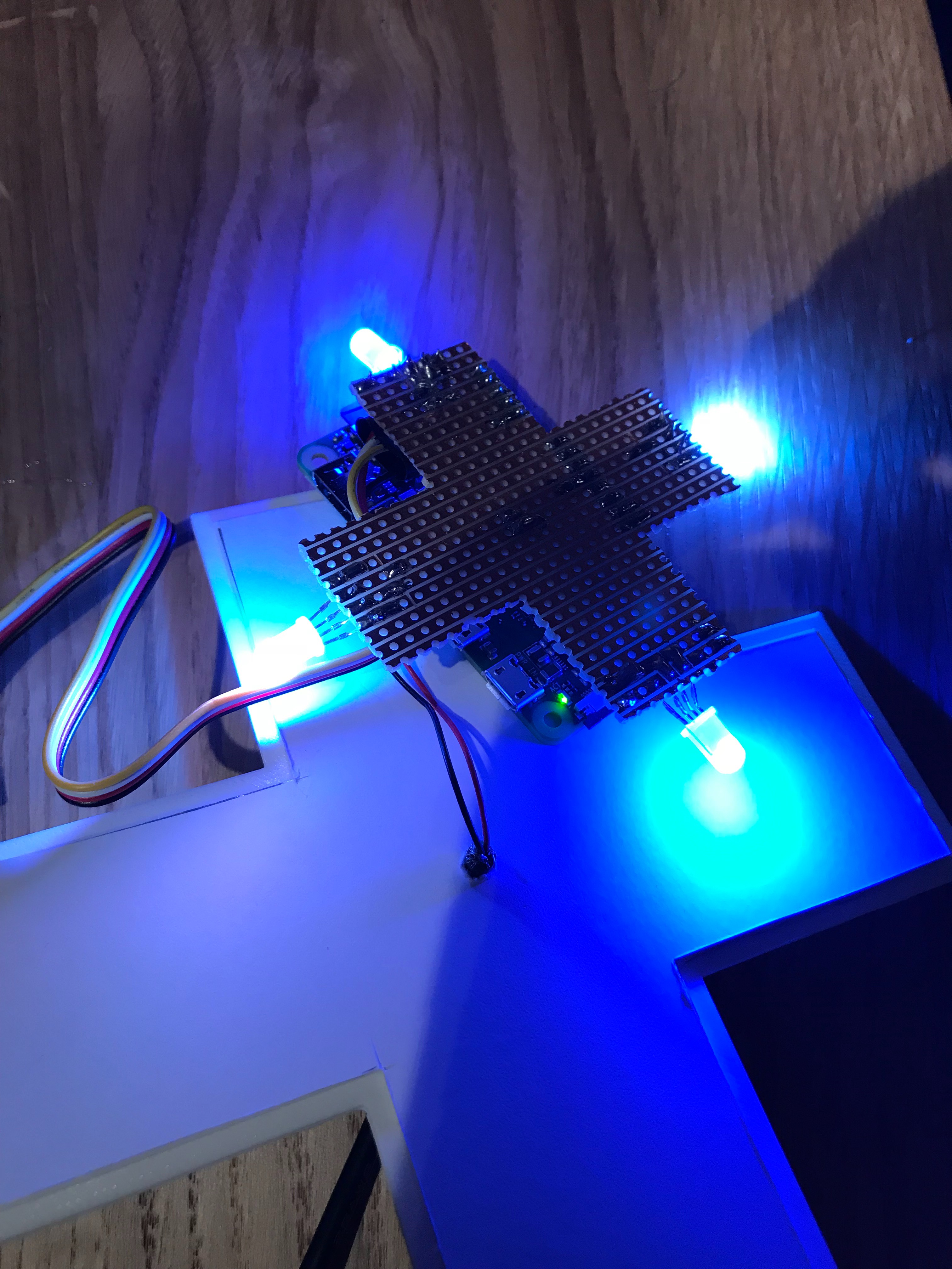
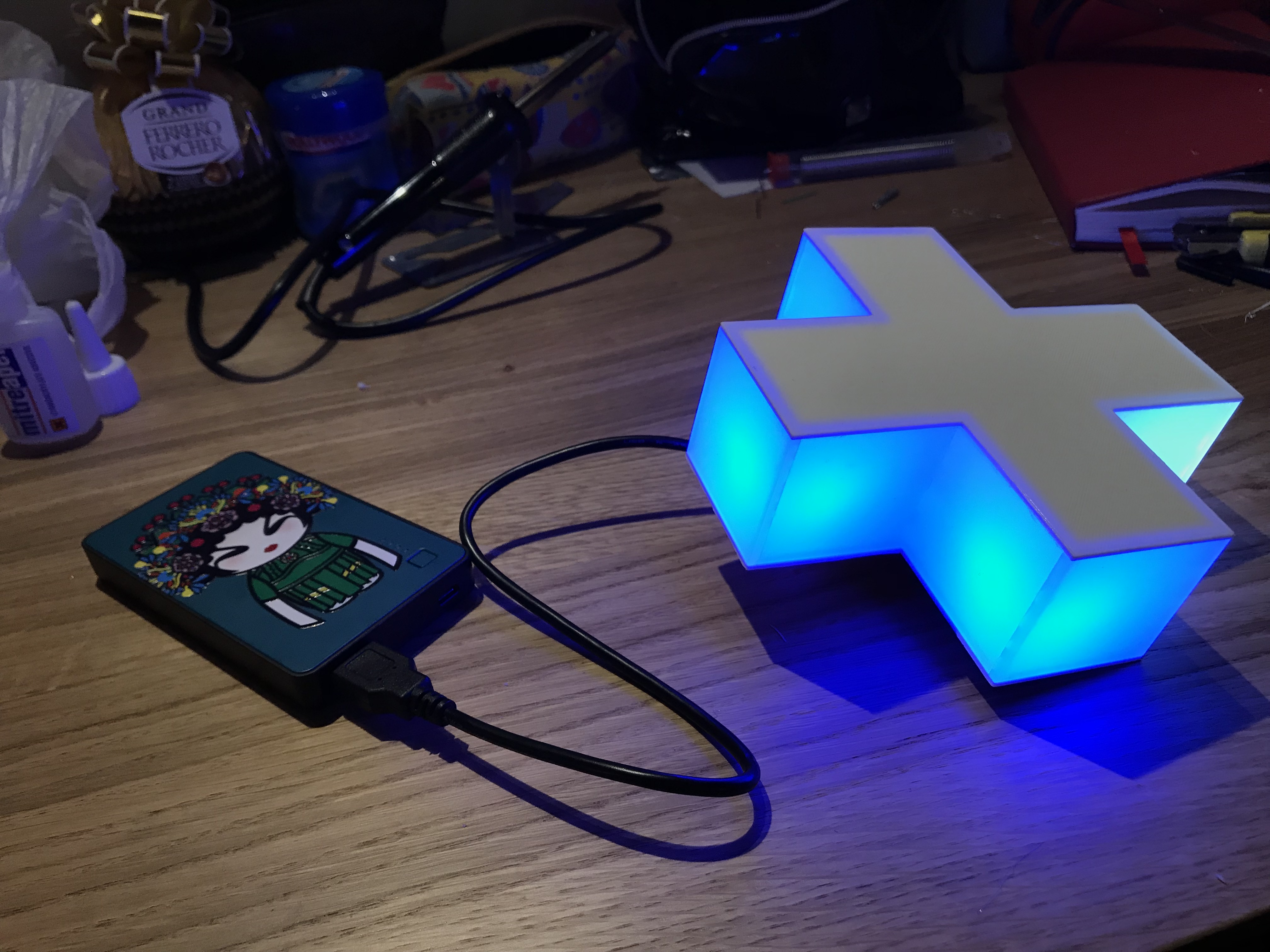
With the 3D printed part, the electronics and software at hand, we can finally assemble the final product.
- The 3D printed top and bottom plates, we found to be more transparent than anticipated. A layer of aluminum foil solved the light leakage issue.
- However, these sheets are conductive and can cause shorts within our unprotected circuit. So another layer of white card board is glued on top.
- The diffuse Plexiglas segments are glued to one of the side plates.
- A hole is drilled in one of the side 3D printed panels. This is so that we can pass through the power cord.
- Once, the power cord is fitted through the hole, we solder it onto our prototyping board.
- We attach the sensor to the raspberry pi and then plug it into the connector.
- We attach the 2 piece together to get our final product.
- Optionally you can glue the 2 piece to make a more permanent connection. However be aware that it maybe hard to get into the box after it's glued shut if you want to change the code later.
Final Test
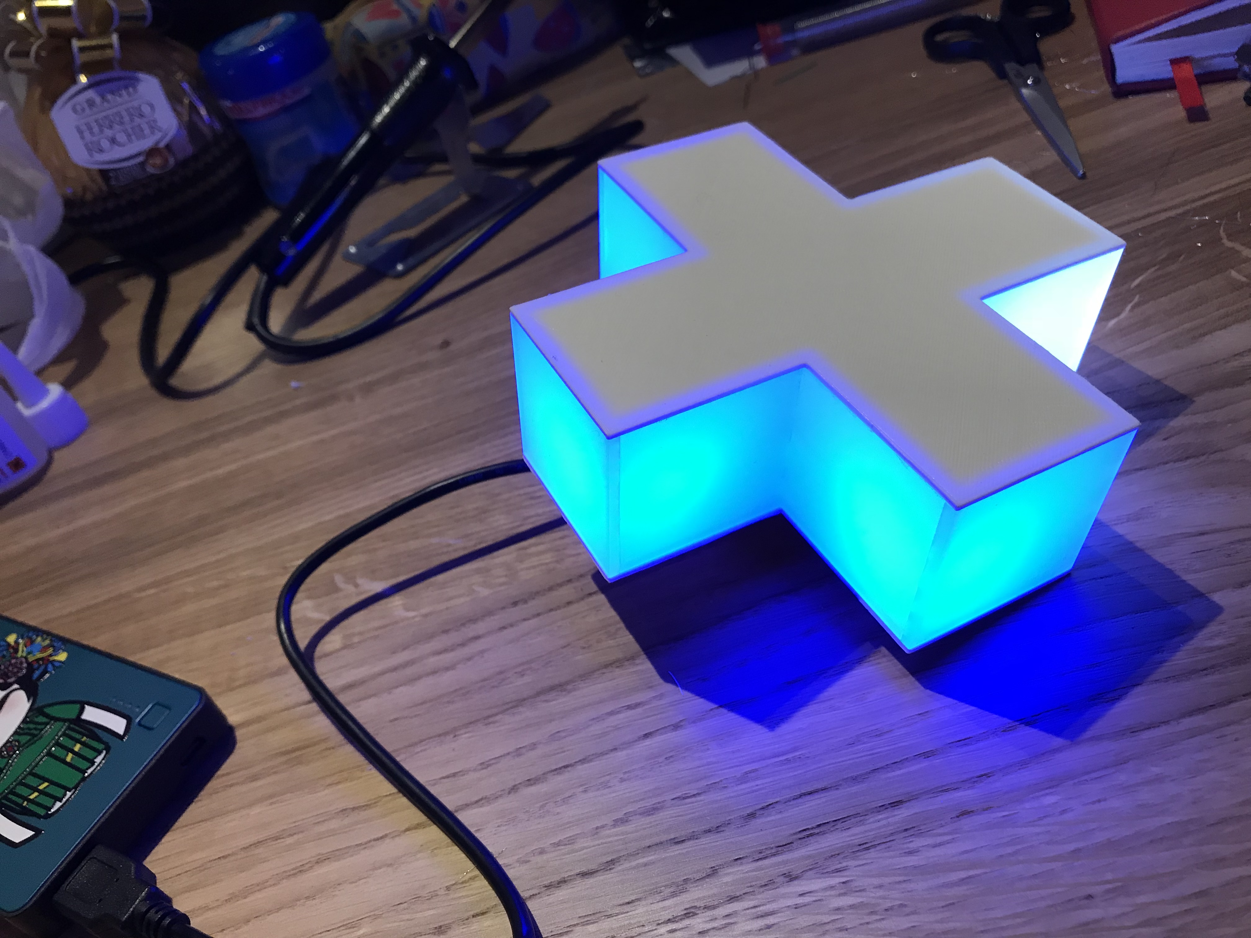
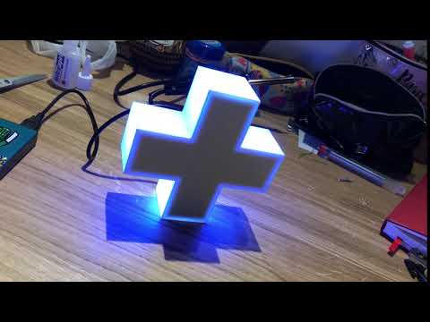
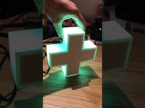
ENJOY!
