Test I2c Oled With Arduino
by hariramanil810 in Circuits > Arduino
2396 Views, 2 Favorites, 0 Comments
Test I2c Oled With Arduino
.png)
If you have hard-time 3d printing stuff and other materials which i have provided in this project please refer the professionals for the help, JLCPCB is one of the best company from shenzhen china they provide, PCB manufacturing, PCBA and 3D printing services to people in need, they provide good quality products in all sectors
Please use the following link to register an account in JLCPCB
Pcb Manufacturing
----------
2 layers
4 layers
6 layers
PCBA Services
JLCPCB have 350k+ Components In-stock. You don’t have to worry about parts sourcing, this helps you to save time and hassle, also keeps your costs down.
Moreover, you can pre-order parts and hold the inventory at JLCPCB, giving you peace-of-mind that you won't run into any last minute part shortages. jlcpcb.com/RNA
3d printing
-------------------
SLA -- MJF --SLM -- FDM -- & SLS. easy order and fast shipping makes JLCPCB better companion among other manufactures try out JLCPCB 3D Printing servies
JLCPCB 3D Printing starts at $1 &Get $54 Coupons for new users
Supplies
.png)
.png)
.png)
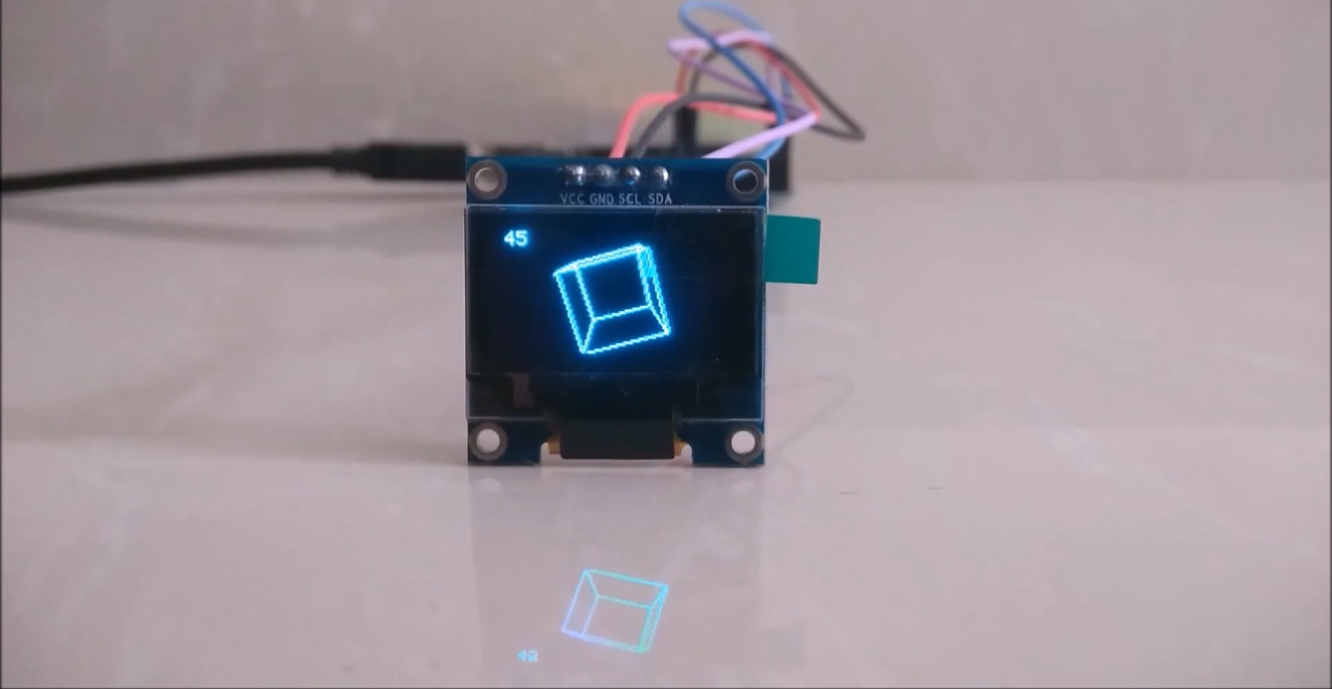
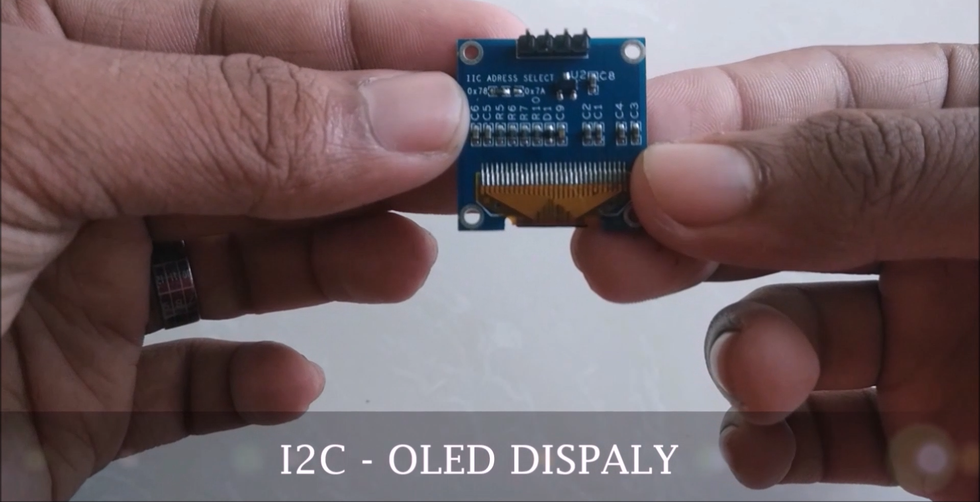
he organic light-emitting diode (OLED) display that we’ll use in this tutorial is the SSD1306 model: a monocolor, 0.96-inch display with 128×64 pixels as shown in the following figure.
The OLED display doesn’t require backlight, which results in a very nice contrast in dark environments. Additionally, its pixels consume energy only when they are on, so the OLED display consumes less power when compared with other displays.
The model we’re using here has only four pins and communicates with the Arduino using I2C communication protocol. There are models that come with an extra RESET pin. There are also other OLED displays that communicate using SPI communication.
Pin wiring
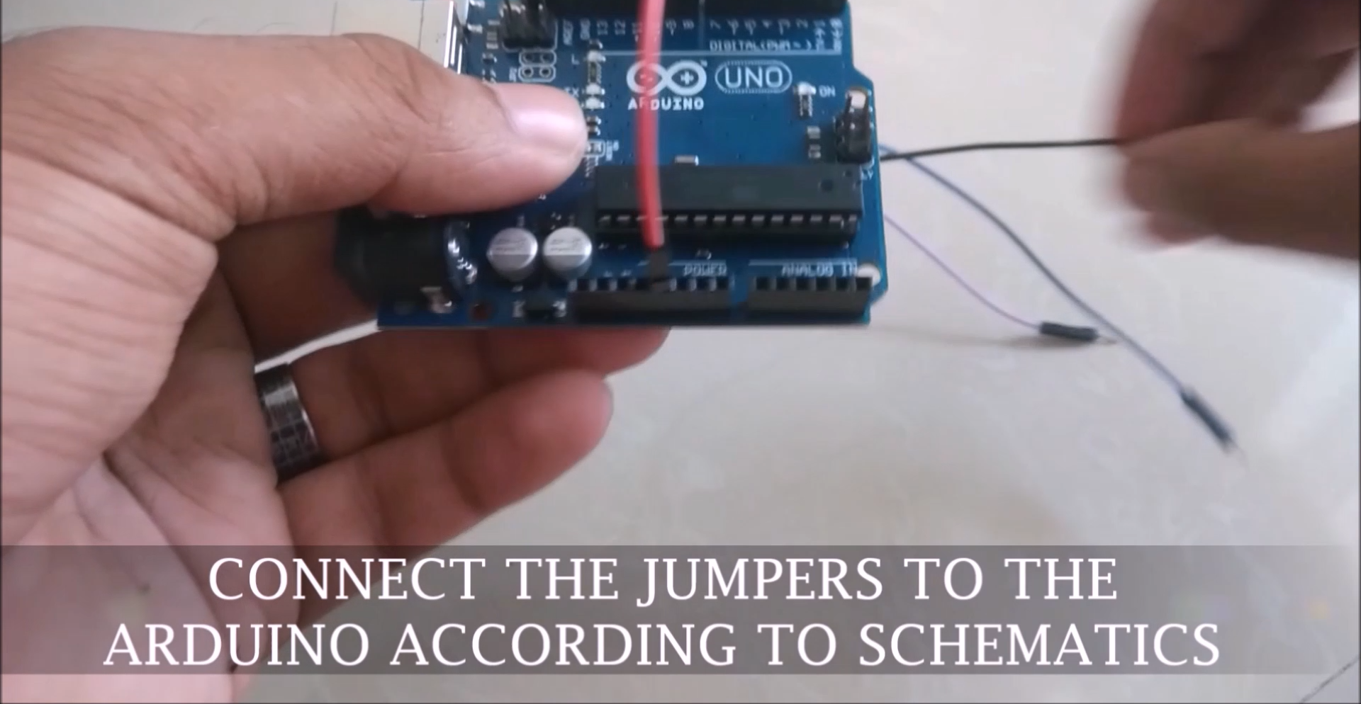
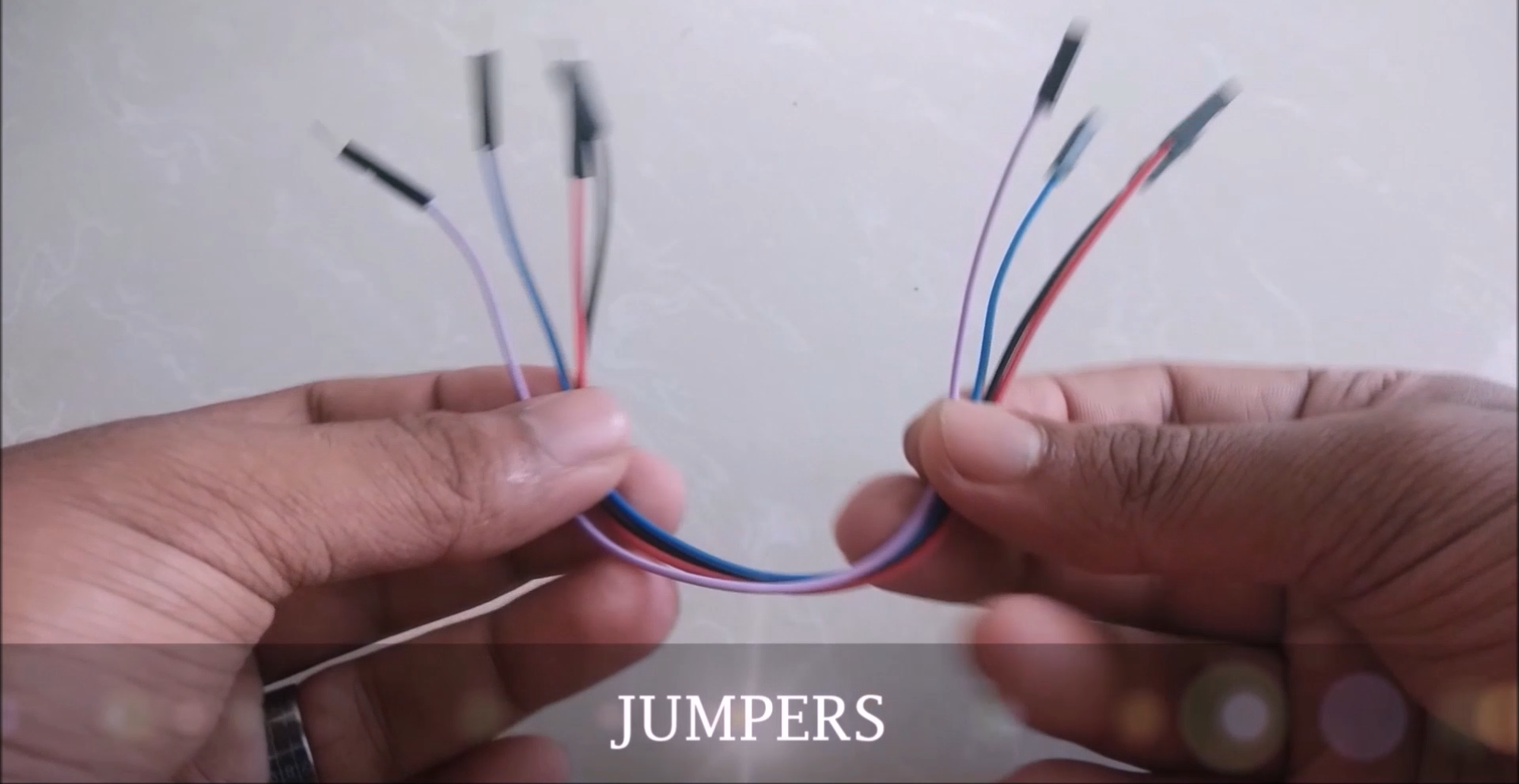
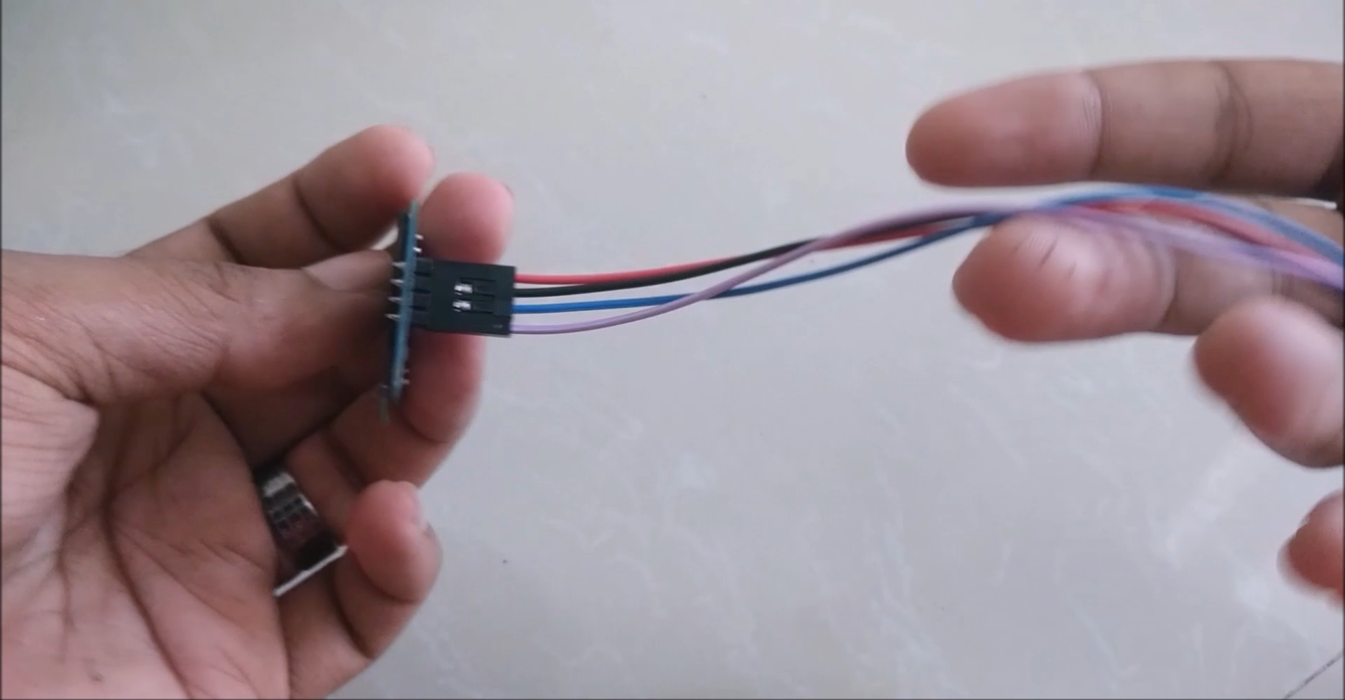
Because the OLED display uses I2C communication protocol, wiring is very simple. You just need to connect to the Arduino Uno I2C pins as shown in the table below.
PinWiring to Arduino UnoVin5VGNDGNDSCLA5SDAA4
If you’re using a different Arduino board, make sure you check the correct I2C pins:
- Nano: SDA (A4); SCL (A5);
- MEGA: SDA (20); SCL (21);
- Leonardo: SDA (20); SCL (21);

Libraries
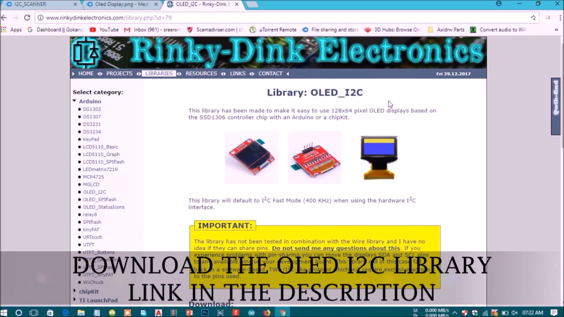
To control the OLED display you need the adafruit_SSD1306.h and the adafruit_GFX.h libraries. Follow the next instructions to install those libraries.
1. Open your Arduino IDE and go to Sketch > Include Library > Manage Libraries. The Library Manager should open.
2. Type “SSD1306” in the search box and install the SSD1306 library from Adafruit.

3. After installing the SSD1306 library from Adafruit, type “GFX” in the search box and install the library.

4. After installing the libraries, restart your Arduino IDE.
Files
.png)
.png)
Tips for writing text using these libraries
Here’s some functions that will help you handle the OLED display library to write text or draw simple graphics.
- display.clearDisplay() – all pixels are off
- display.drawPixel(x,y, color) – plot a pixel in the x,y coordinates
- display.setTextSize(n) – set the font size, supports sizes from 1 to 8
- display.setCursor(x,y) – set the coordinates to start writing text
- display.print(“message”) – print the characters at location x,y
- display.display() – call this method for the changes to make effect
Testing the OLED Display
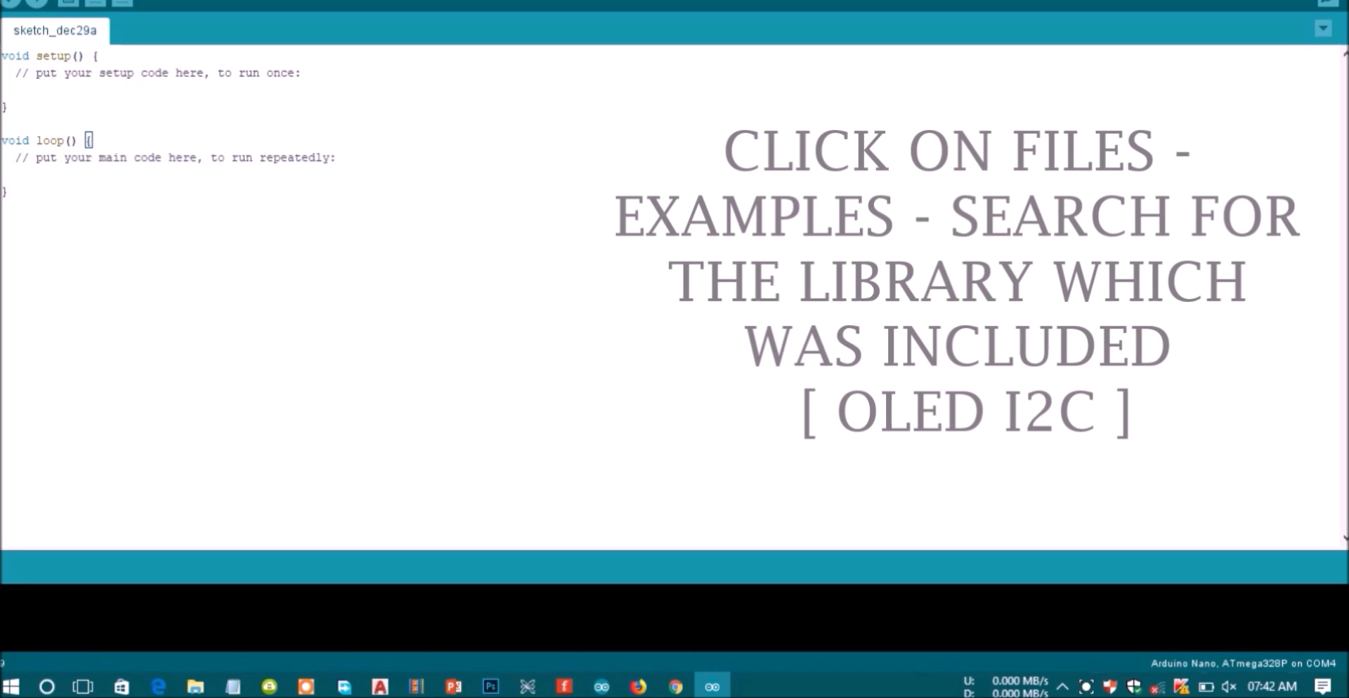
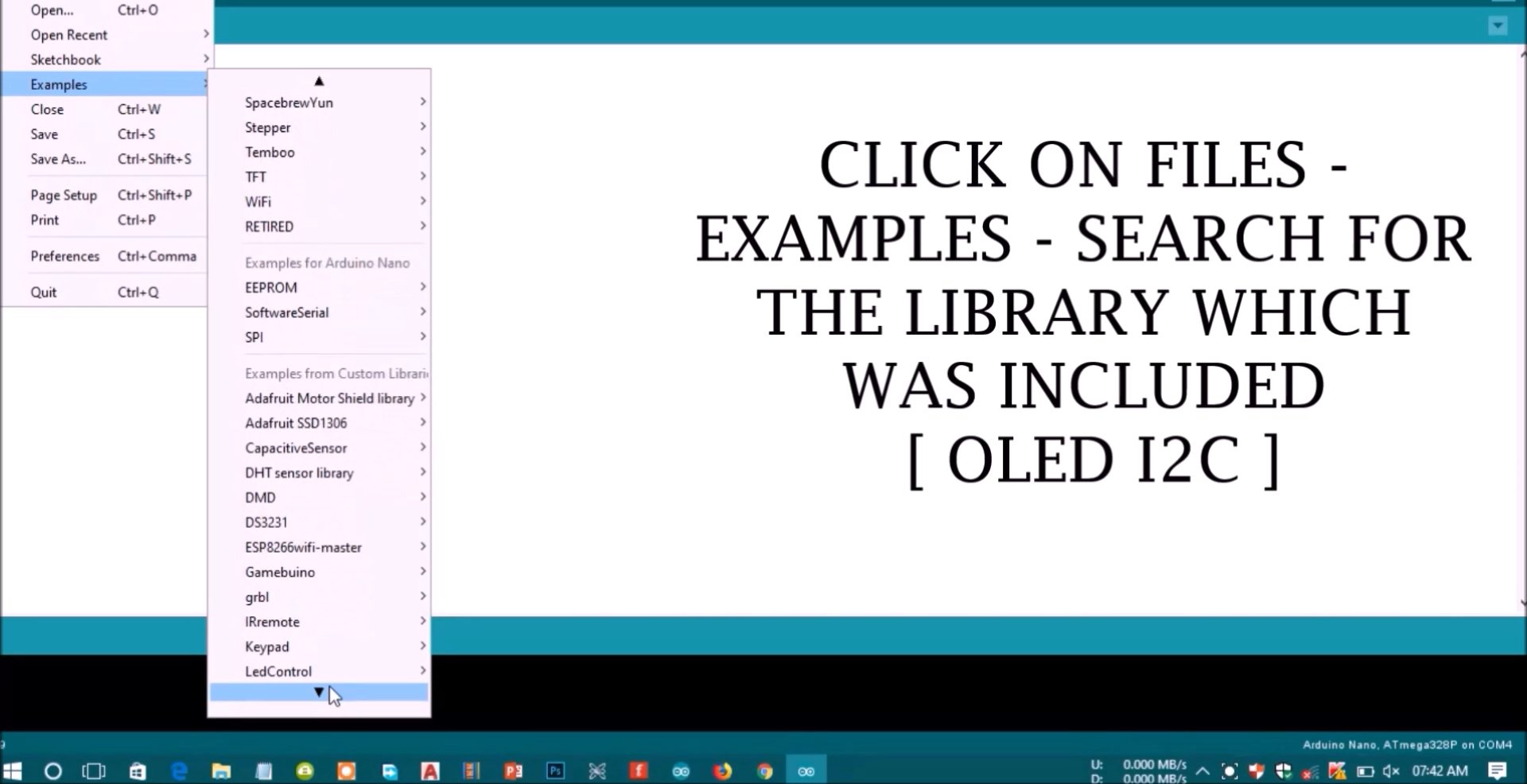
After wiring the OLED display to the Arduino and installing all required libraries, you can use one example from the library to see if everything is working properly.
In your Arduino IDE, go to File > Examples > Adafruit SSD1306 and select the example for the display you’re using.

If your OLED doesn’t have a RESET pin, you should set the OLED_RESET variable to -1 as shown below:
#define OLED_RESET -1 // Reset pin # (or -1 if sharing Arduino reset pin)

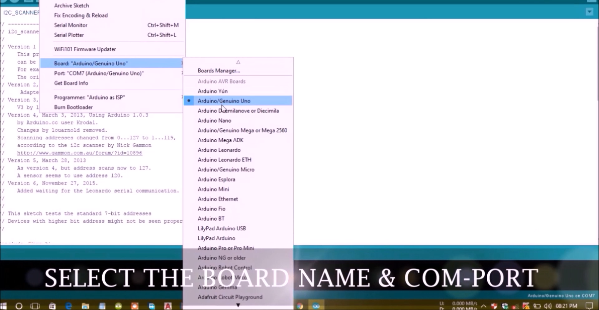
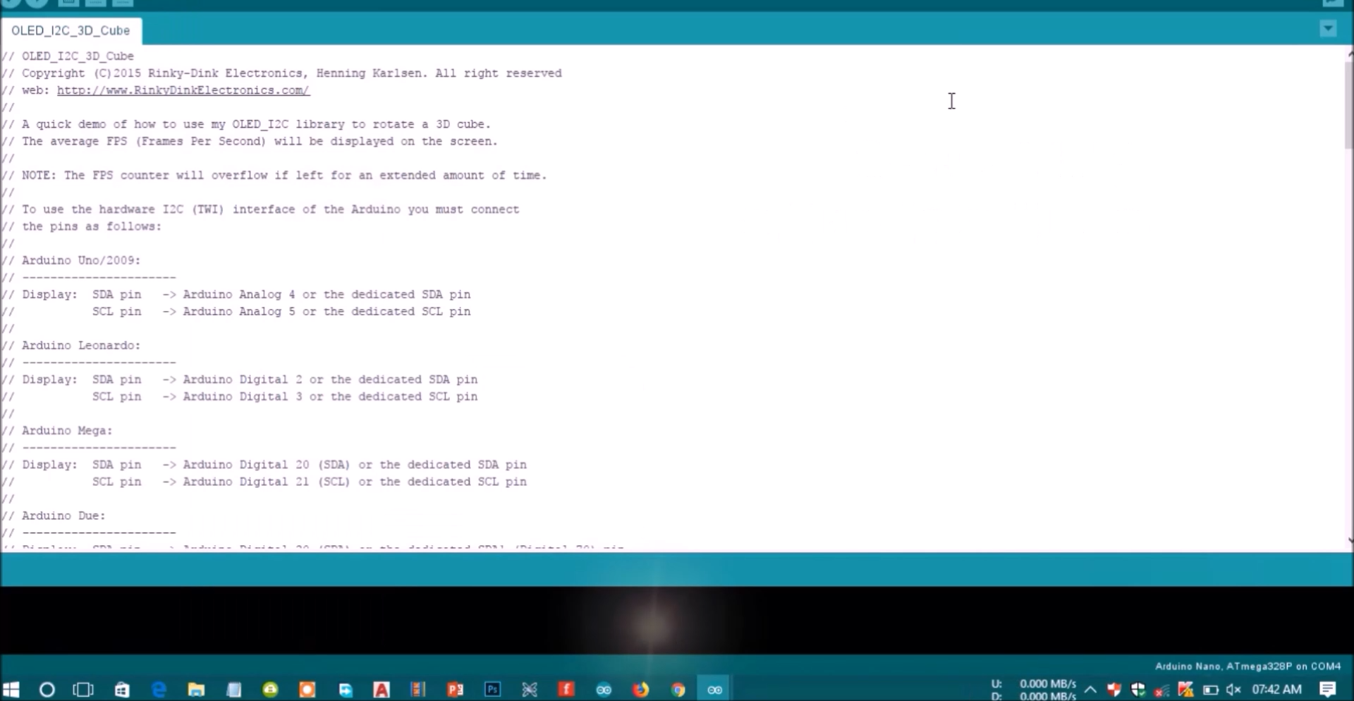
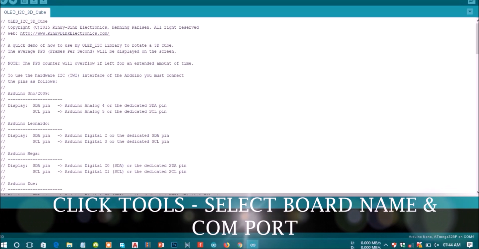
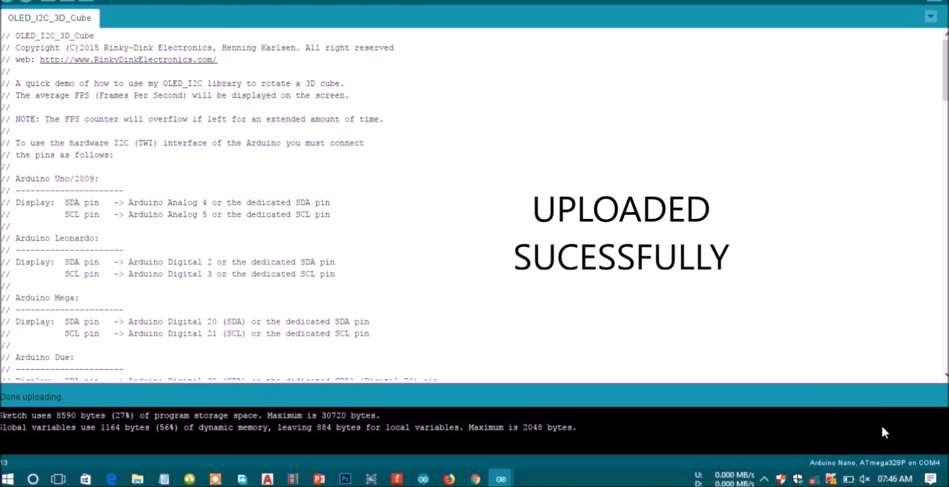
Upload the code to your Arduino board. Don’t forget to select the right board and COM port in the Tools menu.
File
.png)
.png)
If your OLED display is not showing anything:
- Check that the OLED display is properly wired to the Arduino
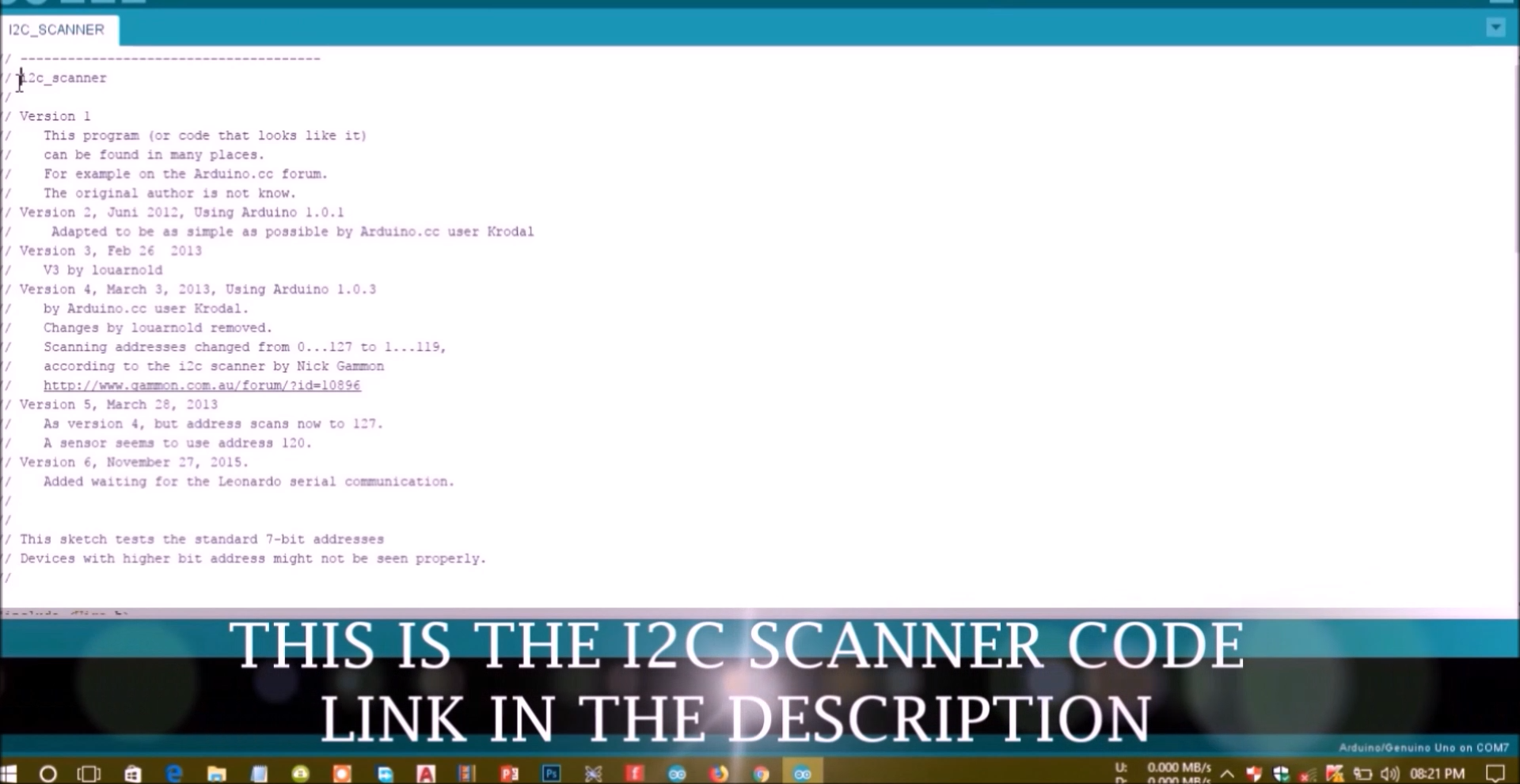
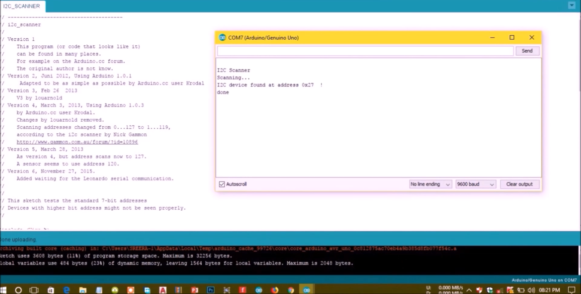
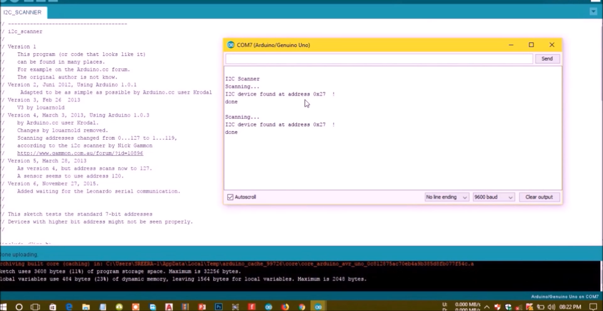
- Double-check the OLED display I2C address: with the OLED connected to the Arduino, upload this code and check the I2C address in the Serial Monitor
You should change the OLED address in the following line, if necessary. In our case, the address is 0x3C.
if(!display.begin(SSD1306_SWITCHCAPVCC, 0x3C)) {
Write Text – OLED Display
The Adafruit library for the OLED display comes with several functions to write text. In this section, you’ll learn how to write and scroll text using the library functions.
“Hello, world!” OLED Display
Importing libraries
First, you need to import the necessary libraries. The Wire library to use I2C and the Adafruit libraries to write to the display: Adafruit_GFX and Adafruit_SSD1306.
#include <Wire.h>
#include <Adafruit_GFX.h>
#include <Adafruit_SSD1306.h>
Initialize the OLED display
Then, you define your OLED width and height. In this example, we’re using a 128×64 OLED display. If you’re using other sizes, you can change that in the SCREEN_WIDTH, and SCREEN_HEIGHT variables.
#define SCREEN_WIDTH 128 // OLED display width, in pixels
#define SCREEN_HEIGHT 64 // OLED display height, in pixels
Then, initialize a display object with the width and height defined earlier with I2C communication protocol (&Wire).
Adafruit_SSD1306 display(SCREEN_WIDTH, SCREEN_HEIGHT, &Wire, -1);
The (-1) parameter means that your OLED display doesn’t have a RESET pin. If your OLED display does have a RESET pin, it should be connected to a GPIO. In that case, you should pass the GPIO number as a parameter.
In the setup(), initialize the Serial Monitor at a baud raute of 115200 for debugging purposes.
Serial.begin(115200);
Initialize the OLED display with the begin() method as follows:
if(!display.begin(SSD1306_SWITCHCAPVCC, 0x3C)) {
  Serial.println("SSD1306 allocation failed");
  for(;;); // Don't proceed, loop forever
}
This snippet also prints a message on the Serial Monitor, in case we’re not able to connect to the display.
Serial.println("SSD1306 allocation failed");
In case you’re using a different OLED display, you may need to change the OLED address. In our case, the address is 0x3C.
if(!display.begin(SSD1306_SWITCHCAPVCC, 0x3C)) {
Library
.png)
Define the position where the text starts using the setCursor(x,y) method. In this case, we’re setting the text to start at the (0,10) coordinates.
display.setCursor(0,10);
Finally, you can send the text to the display using the println() method, as follows:
display.println("Hello, world!");
Then, you need to call the display() method to actually display the text on the screen.
display.display();
Scrolling Text
The Adafruit OLED library provides useful methods to easily scroll text.
- startscrollright(0x00, 0x0F): scroll text from left to right
- startscrollleft(0x00, 0x0F): scroll text from right to left
- startscrolldiagright(0x00, 0x07): scroll text from left bottom corner to right upper corner
- startscrolldiagleft(0x00, 0x07): scroll text from right bottom corner to left upper corner
Data Sender
.png)
The Adafruit GFX library allows us to use some alternate fonts besides the built-in fonts. It allows you to chose between Serif, Sans, and Mono. Each font is available in bold, italic and in different sizes.
The sizes are set by the actual font. So, the setTextSize() method doesn’t work with these fonts. The fonts are available in 9, 12, 18 and 24 point sizes and also contain 7-bit characters (ASCII codes) (described as 7b in the font name).
The fonts that work better with the OLED display are the 9 and 12 points size.
To use one of those fonts, first you need to include it in your sketch, for example:
#include <Fonts/FreeSerif12pt7b.h>
Next, you just need to use the setFont() method and pass as argument, the specified font:
display.setFont(&FreeSerif12pt7b);
After specifying the font, all methods to write text will use that font. To get back to use the original font, you just need to call the setFont() method with no arguments:
display.setFont();
Note: if you’re using a module with a DHT sensor, it normally comes with only three pins. The pins should be labeled so that you know how to wire them. Additionally, many of these modules already come with an internal pull up resistor, so you don’t need to add one to the circuit.
Installing Libraries
Before proceeding, make sure you have installed the“adafruit_GFX.h” and the “adafruit_SSD1306.h” libraries to control the OLED display.
For this project you also need two aditional libraries to read from the DHT sensor: the DHT library and the Adafruit_Sensor library. Follow the next steps to install those libraries
1. Open your Arduino IDE and go to Sketch > Include Library > Manage Libraries. The Library Manager should open.
2. Search for “DHT” on the Search box and install the DHT library from Adafruit.

3. After installing the DHT library from Adafruit, type “Adafruit Unified Sensor” in the search box. Scroll all the way down to find the library and install it.

4. Restart your Arduino IDE.
.png)
.png)
Importing libraries
The code starts by including the necessary libraries. The Wire, Adafruit_GFX and Adafruit_SSD1306 are used to interface with the OLED display. The Adafruit_Sensor and the DHT libraries are used to interface with the DHT22 or DHT11 sensors.
#include <Wire.h>
#include <Adafruit_GFX.h>
#include <Adafruit_SSD1306.h>
#include <Adafruit_Sensor.h>
#include <DHT.h>
Create a display object
Then, define your OLED display dimensions. In this case, we’re using a 128×64 pixel display.
#define SCREEN_WIDTH 128 // OLED display width, in pixels
#define SCREEN_HEIGHT 64 // OLED display height, in pixels
Then, initialize a display object with the width and height defined earlier with I2C communication protocol (&Wire).
Adafruit_SSD1306 display(SCREEN_WIDTH, SCREEN_HEIGHT, &Wire, -1);
The (-1) parameter means that your OLED display doesn’t have a RESET pin. If your OLED display does have a RESET pin, it should be connected to a GPIO. In that case, you should pass the GPIO number as a parameter.
Create a DHT object
Then, define the DHT sensor type you’re using. If you’re using a DHT11 you don’t need to change anything on the code. If you’re using another sensor, just uncomment the sensor you’re using and comment the others.
#define DHTTYPE    DHT11     // DHT 11
//#define DHTTYPE    DHT22     // DHT 22 (AM2302)
//#define DHTTYPE    DHT21     // DHT 21 (AM2301)
Initialize a DHT sensor object with the pin and type defined earlier.
DHT dht(DHTPIN, DHTTYPE);
setup()
In the setup(), initialize the serial monitor for debugging purposes.
Serial.begin(115200);
Initialize the DHT sensor:
dht.begin();
Then, initialize the OLED display.
if(!display.begin(SSD1306_SWITCHCAPVCC, 0x3C)) { // Address 0x3D for 128x64
  Serial.println(F("SSD1306 allocation failed"));
  for(;;);
}
In this case, the address of the OLED display we’re using is 0x3C. If this address doesn’t work, you can run an I2C scanner sketch to find your OLED address. You can find the I2C scanner sketch here.
Add a delay to give time for the display to initialize, clear the display and set the text color to white:
delay(2000);
display.clearDisplay();
display.setTextColor(WHITE)
.png)
.png)
Get temperature and humidity readings from DHT
The temperature and humidity are saved on the t and h variables, respectively. Reading temperature and humidity is as simple as using the readTemperature() and readHumidity() methods on the dht object.
float t = dht.readTemperature();
float h = dht.readHumidity();
In case we are not able to get the readings, display an error message:
if (isnan(h) || isnan(t)) {
  Serial.println("Failed to read from DHT sensor!");
}
If you get that error message, read our troubleshooting guide: how to fix “Failed to read from DHT sensor”.
Display sensor readings on the OLED display
The following lines display the temperature on the OLED display.
  display.setTextSize(1);
  display.setCursor(0,0);
  display.print("Temperature: ");
  display.setTextSize(2);
  display.setCursor(0,10);
  display.print(t);
  display.print(" ");
  display.setTextSize(1);
  display.cp437(true);
  display.write(167);
  display.setTextSize(2);
  display.print("C");
We use the setTextSize() method to define the font size, the setCursor() sets where the text should start being displayed and the print() method is used to write something on the display.
To print the temperature and humidity you just need to pass their variables to the print() method as follows:
display.print(t);
The “Temperature” label is displayed in size 1, and the actual reading is displayed in size 2.
To display the º symbol, we use the Code Page 437 font. For that, you need to set the cp437 to true as follows:
display.cp437(true);
Then, use the write() method to display your chosen character. The º symbol corresponds to character 167.
display.write(167);
A similar approach is used to display the humidity:
display.setTextSize(1);
display.setCursor(0, 35);
display.print("Humidity: ");
display.setTextSize(2);
display.setCursor(0, 45);
display.print(h);
display.print(" %");
Don’t forget that you need to call display.display() at the end, so that you can actually display something on the OLED.
display.display();
Wiring
.png)
.png)
.png)
If your DHT sensor fails to get the readings or you get the message “Failed to read from DHT sensor”
If you get the “SSD1306 allocation failed” error or if the OLED is not displaying anything in the screen, it can be one of the following issues:
Wrong I2C address
The I2C address for the OLED display we are using is 0x3C. However, yours may be different. So, make sure you check your display I2C address using an I2C scanner sketch.
SDA and SCL not connected properly
Please make sure that you have the SDA and SCL pins of the OLED display wired correctly.
One thing they all have in common, however, is that at their core is a powerful single-chip CMOS OLED driver controller – SSD1306, which handles all RAM buffering, requiring very little work from your Arduino.
In this tutorial, we’ll be using both I2C and SPI 0.96-inch 128×64 OLED displays. Don’t worry if your module is a different size or color;
An OLED display, unlike a character LCD display, does not require a backlight because it generates its own light. This explains the display’s high contrast, extremely wide viewing angle, and ability to display deep black levels. The absence of a backlight reduces power consumption significantly. The display uses about 20mA on average, though this varies depending on how much of the display is lit.
The SSD1306 controller operates at 1.65V to 3.3V, while the OLED panel requires a 7V to 15V supply voltage. All of these various power requirements are fulfilled by internal charge pump circuitry. This makes it possible to connect the display to an Arduino or any other 5V logic microcontroller without requiring a logic level converter.
OLED Memory Map
In order to control the display, it is crucial to understand the memory map of the OLED display.
Regardless of the size of the OLED display, the SSD1306 driver includes a 1KB Graphic Display Data RAM (GDDRAM) that stores the bit pattern to be displayed on the screen. This 1 KB memory area is divided into 8 pages (from 0 to 7). Each page has 128 columns/segments (block 0 to 127). And, each column can store 8 bits of data (from 0 to 7). That certainly proves that we have: