Temperature and Light Sensor
by gryffinmedina804 in Circuits > Arduino
582 Views, 0 Favorites, 0 Comments
Temperature and Light Sensor
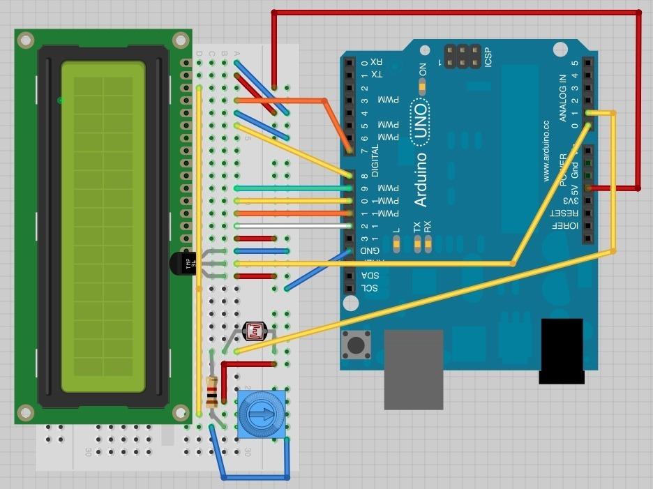
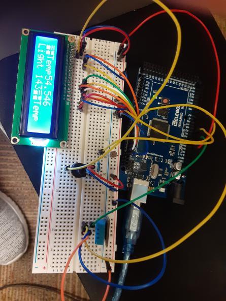
This instructable is for a basic temperature and light sensor. That's about it.
Supplies
-23 Jump Cables
-1 10k Potentiometer
-1k Resistor
-LCD Display
-Breadboard
-Photoresistor
-Arduino 2560
Step One: Acquire Supplies
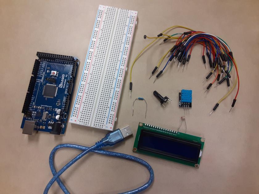
Make sure your supplies are gathered and ready to be used. They can be replaced if found as faulty, but it is good to have a place holder as you put together the circuitry.
Step Two: Insert LCD and Attach
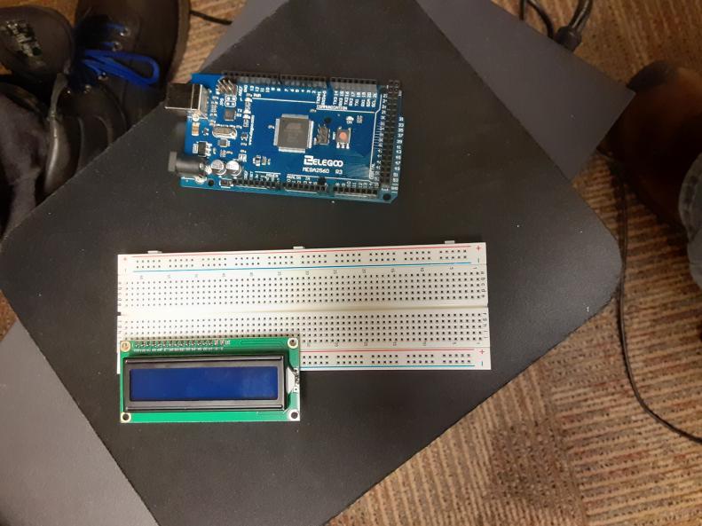
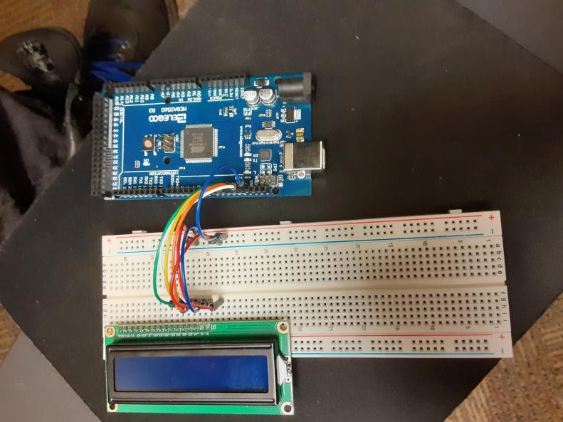
Fig. 3 and Fig. 4 show the proper way of inserting the LCD display and first half of jump cables between breadboard and Arduino.
Step Three: Finish Attaching Breadboard With LCD to Arduino
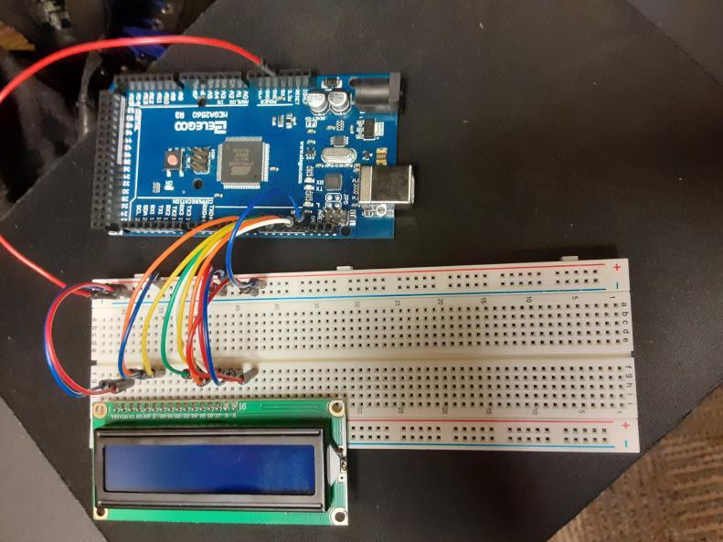
Step Three: Finish Attaching Breadboard with LCD to Arduino Fig. 5 shows the second half of the jump cables between the breadboard and Arduino.
Step Four: Insert and Connect the Potentiometer
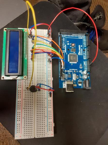
Fig. 6 Shows an easy way to insert and connect the potentiometer so as not to get in the way in future steps. (Note: The potentiometer may not go into the breadboard securely. Make sure you are securing it when you power up the circuit.)
Step Five: Place and Connect the Sensors
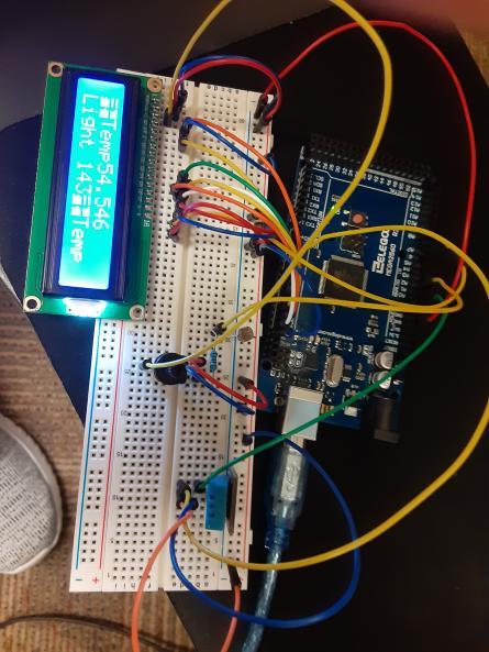
Fig. 7 shows the proper placement and connection points for the and coinciding jump cables to connect them properly to the LCD and Arduino. Please make sure that the photoresistor has access to proper light levels and is not being blocked by any jump cables or other circuitry bits.
Step Six: Connect Computer and Arduino and Upload Code
The code can be found at https://learn.adafruit.com/adafruit-arduino-lesson-12-lcd-displays-part-2/arduino-code
(Optional) Step Seven: Alter Code Depending on Temperature Sensor in Use
The TMP36 temperature sensor is what is used with the current code, but we used the DHT11 humidity and temperature sensor. Since this sensor sends a different data value, the code must be changed to view the temperature correctly.
Make sure to download the DHT11 library from the following link and add it to your library database and code.
https://github.com/adidax/dht11
#include <LiquidCrystal.h>
#include <dht11.h>
#define DHT11PIN 4
int lightPin = 1;
int tempPin = 4;
// BS E D4 D5 D6 D7
LiquidCrystal lcd(7, 8, 9, 10, 11, 12);
dht11 DHT11;
void setup()
{
lcd.begin(16, 2);
}
void loop()
{
  Serial.println();

  int chk = DHT11.read(DHT11PIN);

  Serial.print("Humidity (%): ");
  Serial.println((float)DHT11.humidity, 2);

  Serial.print("Temperature (C): ");
  Serial.println((float)DHT11.temperature, 2);

// Display Temperature in C
lcd.println();
int tempReading = analogRead(tempPin);
float tempVolts = tempReading * 5.0 / 1024.0;
float tempC = tempVolts * 11.1;
float tempF = (tempC * 9) / 5 + 32;
lcd.print("Temp F ");
lcd.setCursor(6, 0);
lcd.print(tempF);

// Display Light on second row
int lightReading = analogRead(lightPin);
lcd.setCursor(0, 1);
// ----------------
lcd.print("Light ");
lcd.setCursor(6, 1);
lcd.print(lightReading);
delay(500);
}
Step Eight: Enjoy Your Newfound Knowledge
Congratulations, viewer. If you have followed the past 7 steps, you will now have a functioning temperature and light sensor on your hands. Use what you have learned for good, not evil.
Disclaimer: If you use this technology for evil, the creators of this instructable do not hold any responsibility for what you do.