Tattlebrush
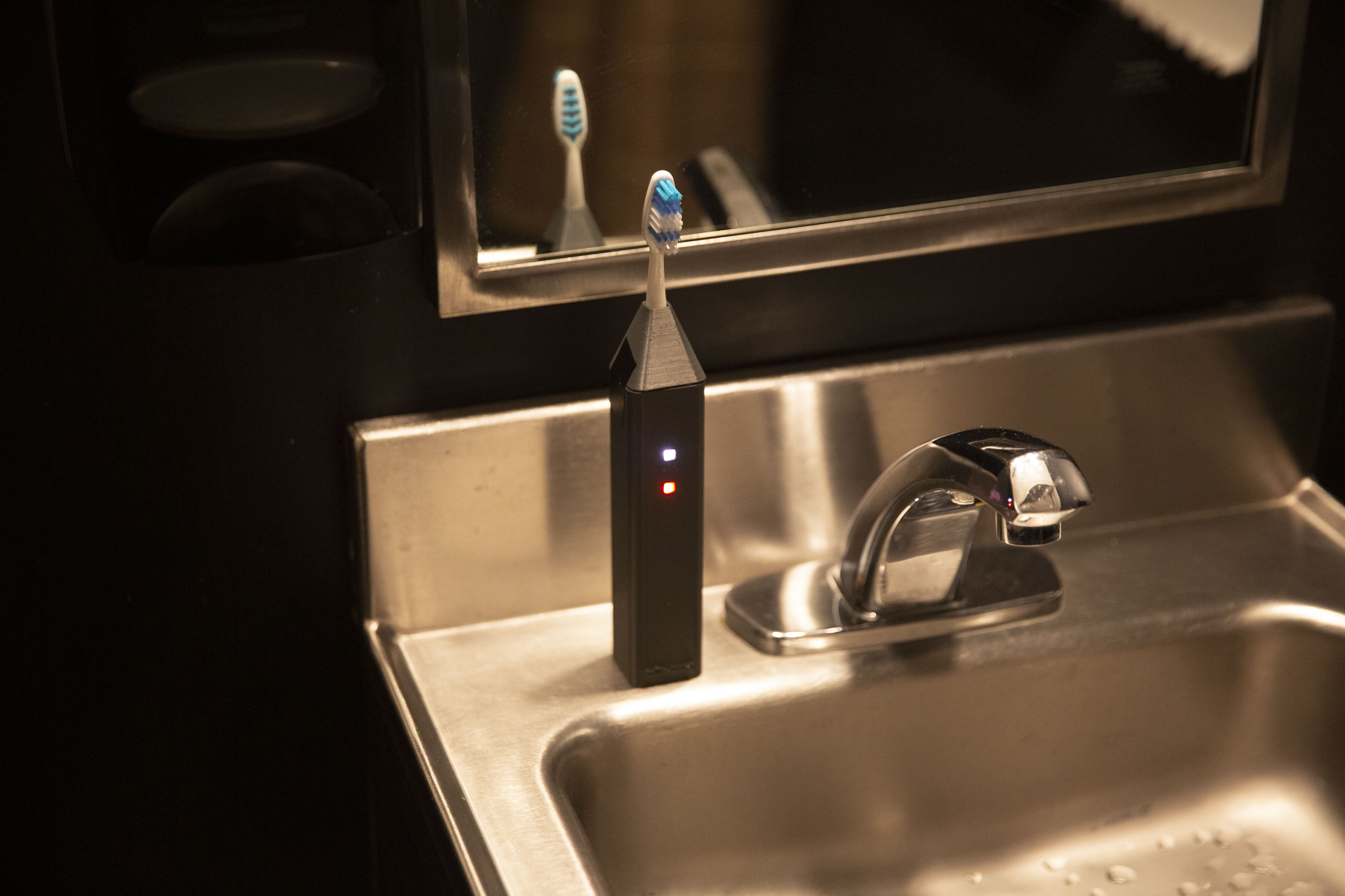
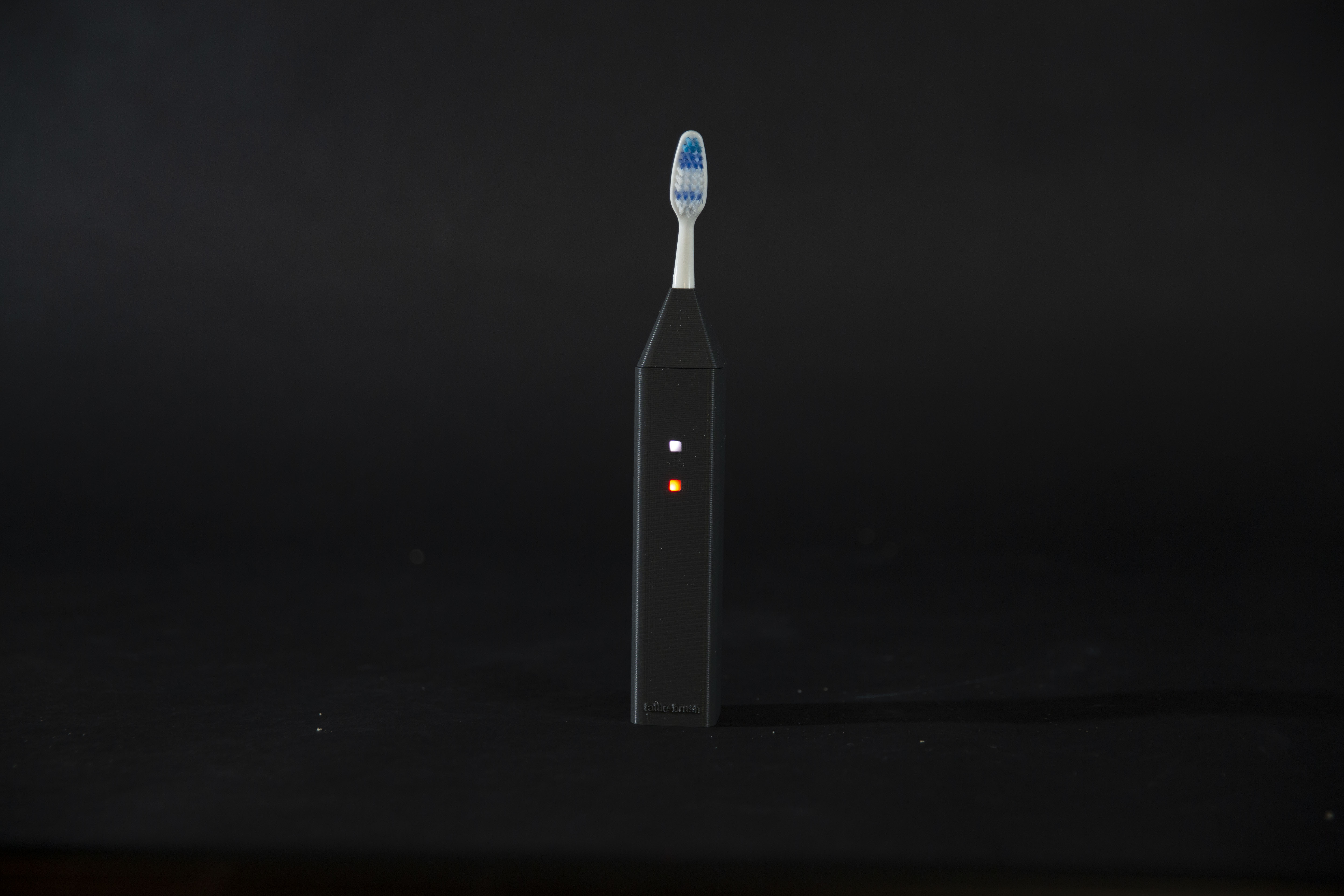
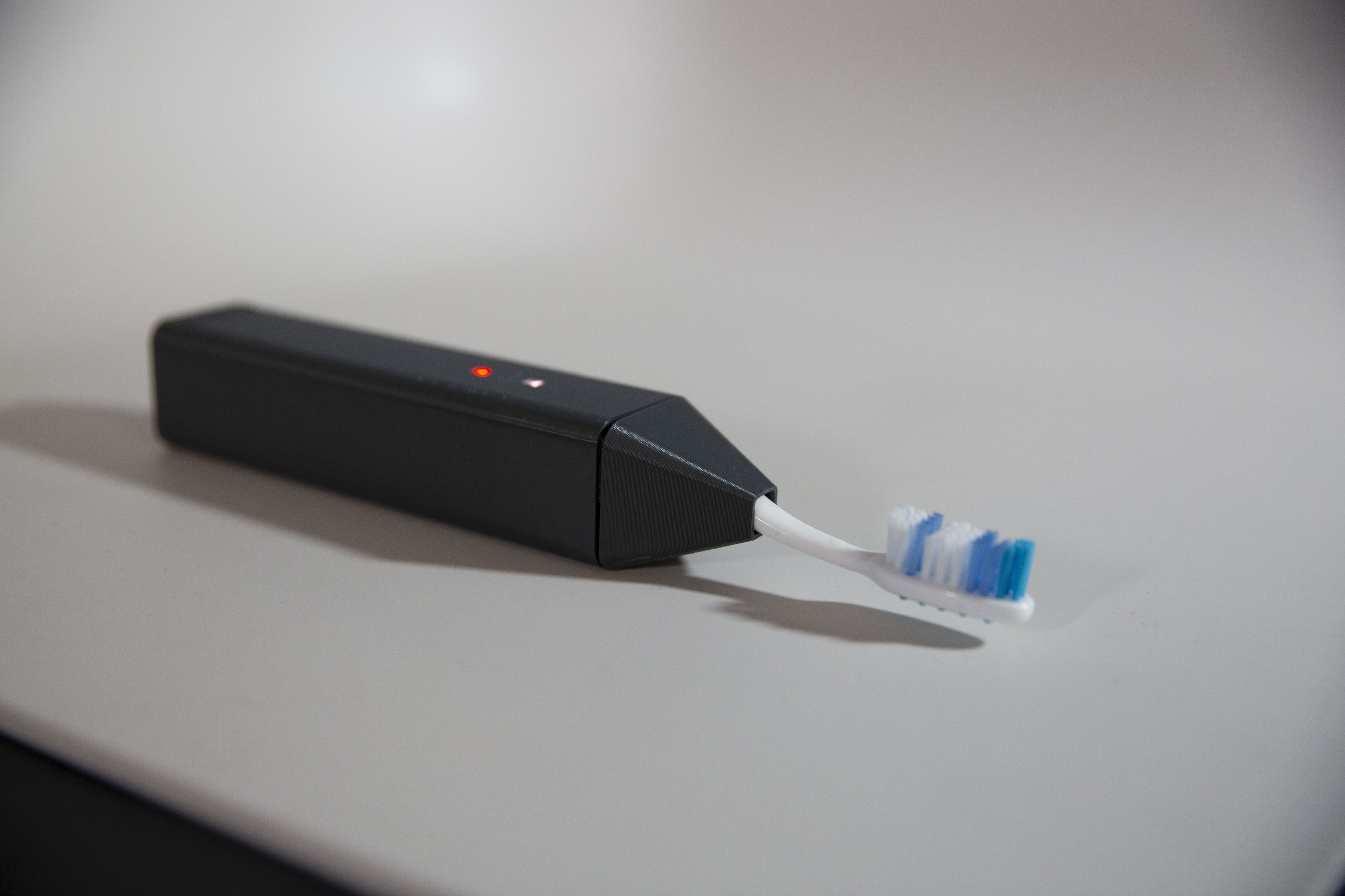
If you have ever made brushing your teeth twice a day as a New Year’s resolution, this toothbrush is for you. It will enforce you to brush twice daily for two minutes by putting you in embarrassing situations you would never want to face. It will determine if you have brushed twice daily for two minutes each time, If you have not, then it will tweet a message on your behalf that you have not brushed today with a meme. In short it will tattle your little secret on Twitter.
The first part covers the electronic circuit of the sleeve.
The second part is divided into two parts. The first part covers the code required to be uploaded on the circuit for the device to work. The second part covers the service to be set up that listens to the device and posts messages on Twitter. The third part of the tutorial is about making the toothbrush.
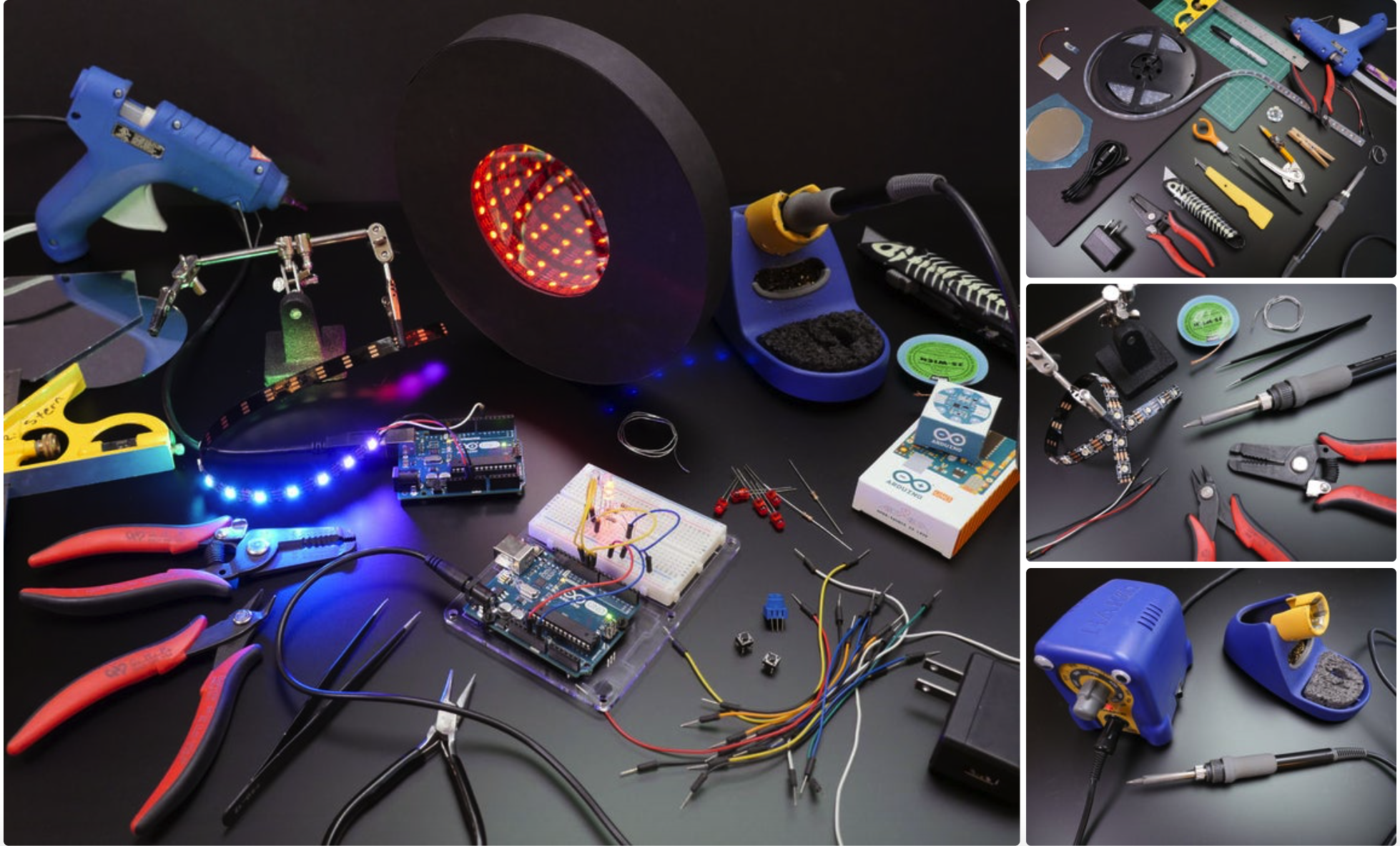
Supplies
Adafruit Huzzah ESP8266
Fast Vibration Sensor
2 neopixels
A couple of stranded wires
3.7 V LiPoly Battery
Wire cutters
Soldering gun
Sharp utility knife
Metal ruler
Hot melt glue gun,
solderless breadboard on a mounting plate
USB A-B cable
Soldering iron & solderWire strippers
Third hand tool Multimeter (optional)
Small needlenose pliers
Tweezers
Building the Circuit

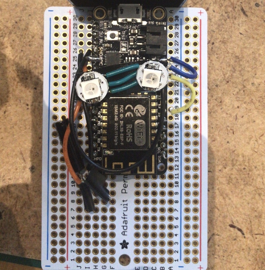
Gather Components:
We will require the following components to complete building the circuit.
1 x ESP8266 Huzzah Board
1 x proto board
2 x Neopixel Mini Button PCB
1 x Fast Vibration Switch
And some stranded wires
Before beginning, I would like to highlight that the circuit will be put inside an object which has limited space. so reducing the space of the circuit is extremely important in the process. Try and keep the length of the wires to the bare minimum.
Circuit Diagram:
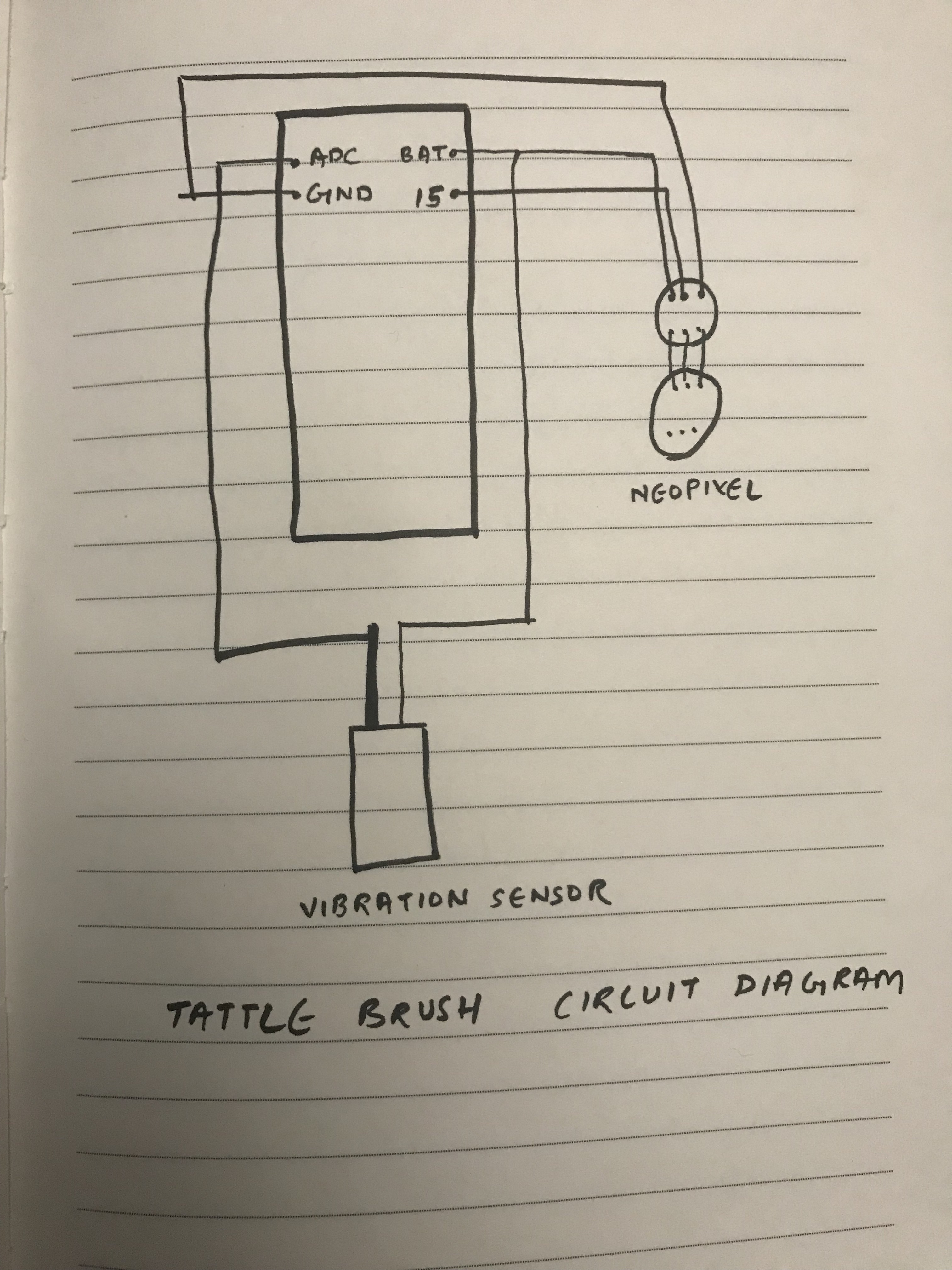
The connections are pretty easy, see the above image.
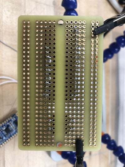
We will start by soldering the Huzzah board on the protoboard to help keep things organized and still have a less footprint.
Then we will proceed to connect the neopixel to the Huzzah Board.
- Make the connections between two Neopixel. Make sure that the output of the 1st Neopixel is fed to the input of the 2nd Neopixel.
- Connect the wire from 5V of the 1st Neopixel to the pin labeled BAT.
- Connect the wire from GND of the 1st Neopixel to the pin labeled GND.
- Connect the wire from Din (INPUT) of the 1st Neopixel to pin labeled 15.
Next up, we will connect the Fast Vibration switch.
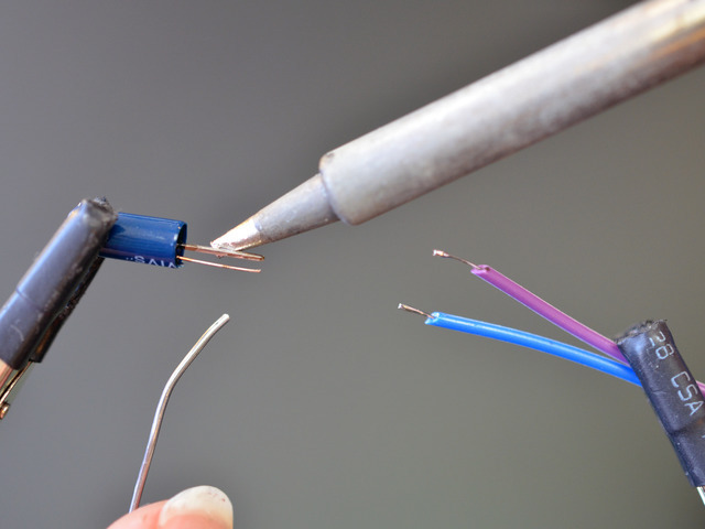
Making connections to the vibration switch could be tedious, especially since the thin leg requires special care to make the connections. To prepare your vibration switch, set it up in a pair of helping hands and tin the leads with a little solder.
Also strip and tin two stranded wires.
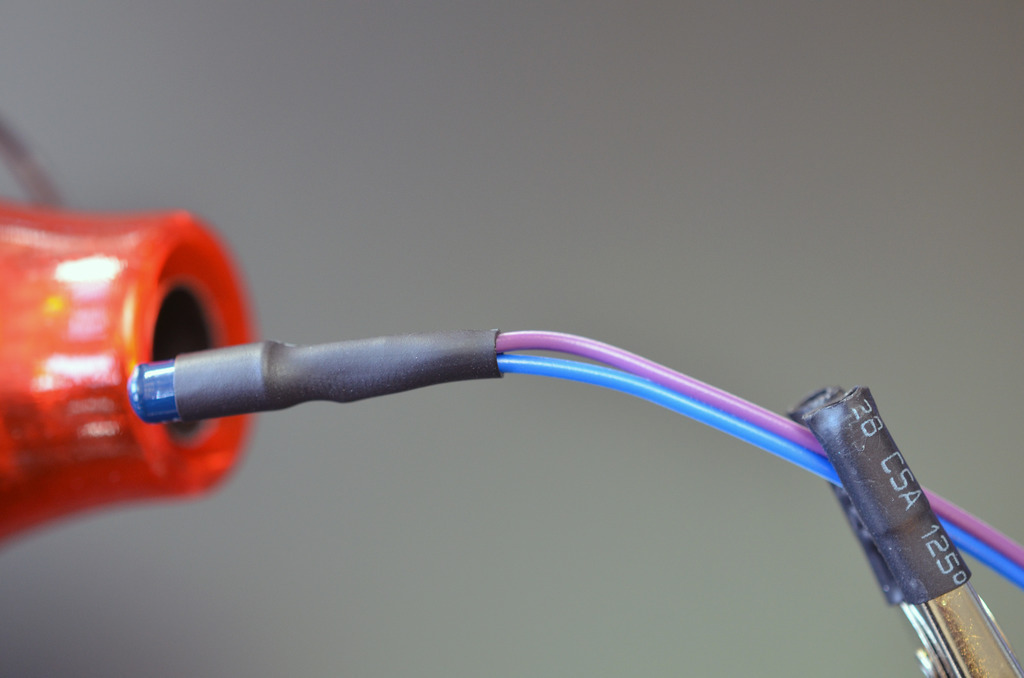
Apply a small piece of heat shrink tubing and reflow the solder between that wire and the center pole of the vibration switch
Slide the heat shrink tubing over the joint and solder the other wire to the outer pole of the vibration switch.
Use a larger piece of heat shrink tubing to cover the while union. That outer wire is pretty fragile, so this heat shrink tubing adds some stability by also bridging the can of the switch, so make sure your piece is long enough to cover everything! While applying heat, make sure that you don't apply too much direct heat to the sensor, since it may get deformed because of the temperature and provide faulty results.
Connect the thicker pin of vibration sensor to Arduino Analog pin A0 or ADC.
Connect the thin pin of vibration sensor to Arduino pin BAT.
Hurray, you are done with the setup of the circuit required for the project.
Writing the Code & Creating the Applet
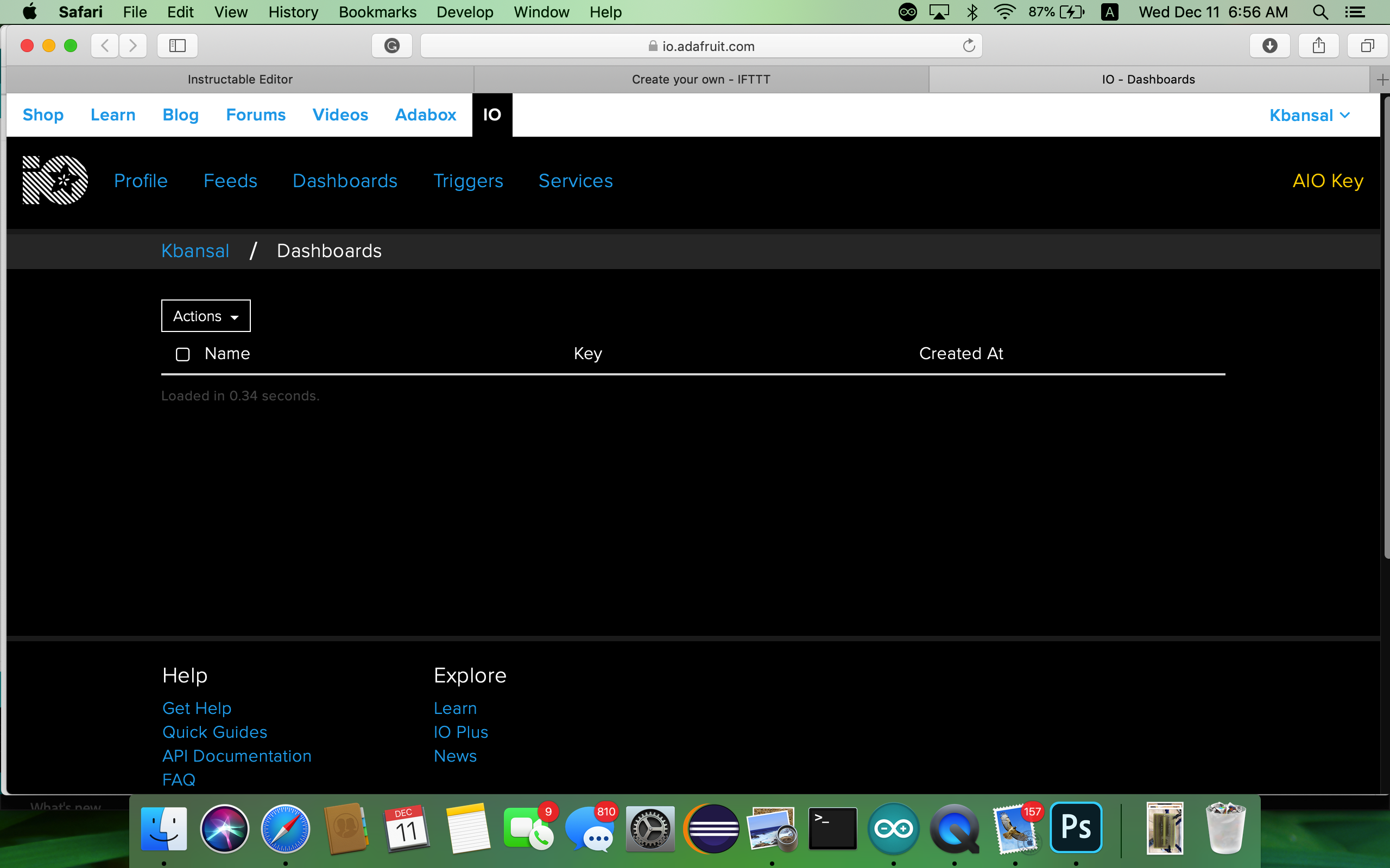
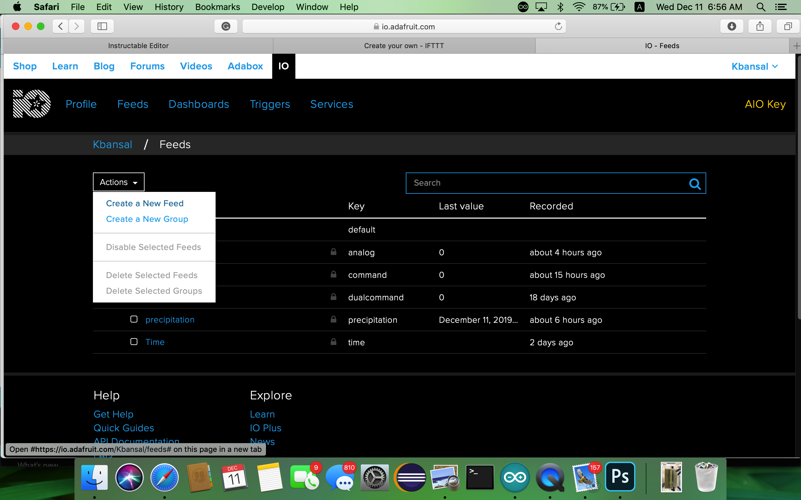
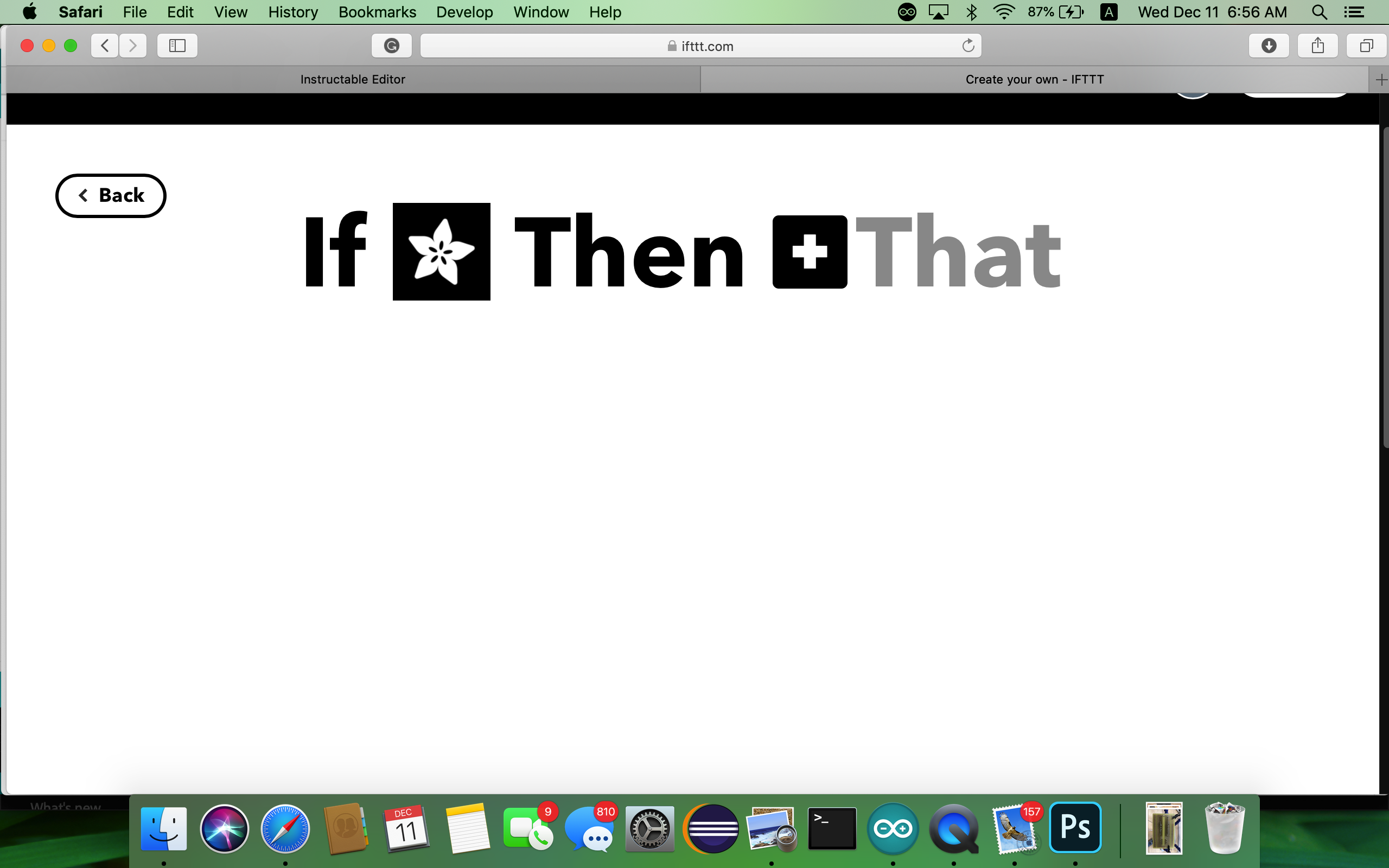
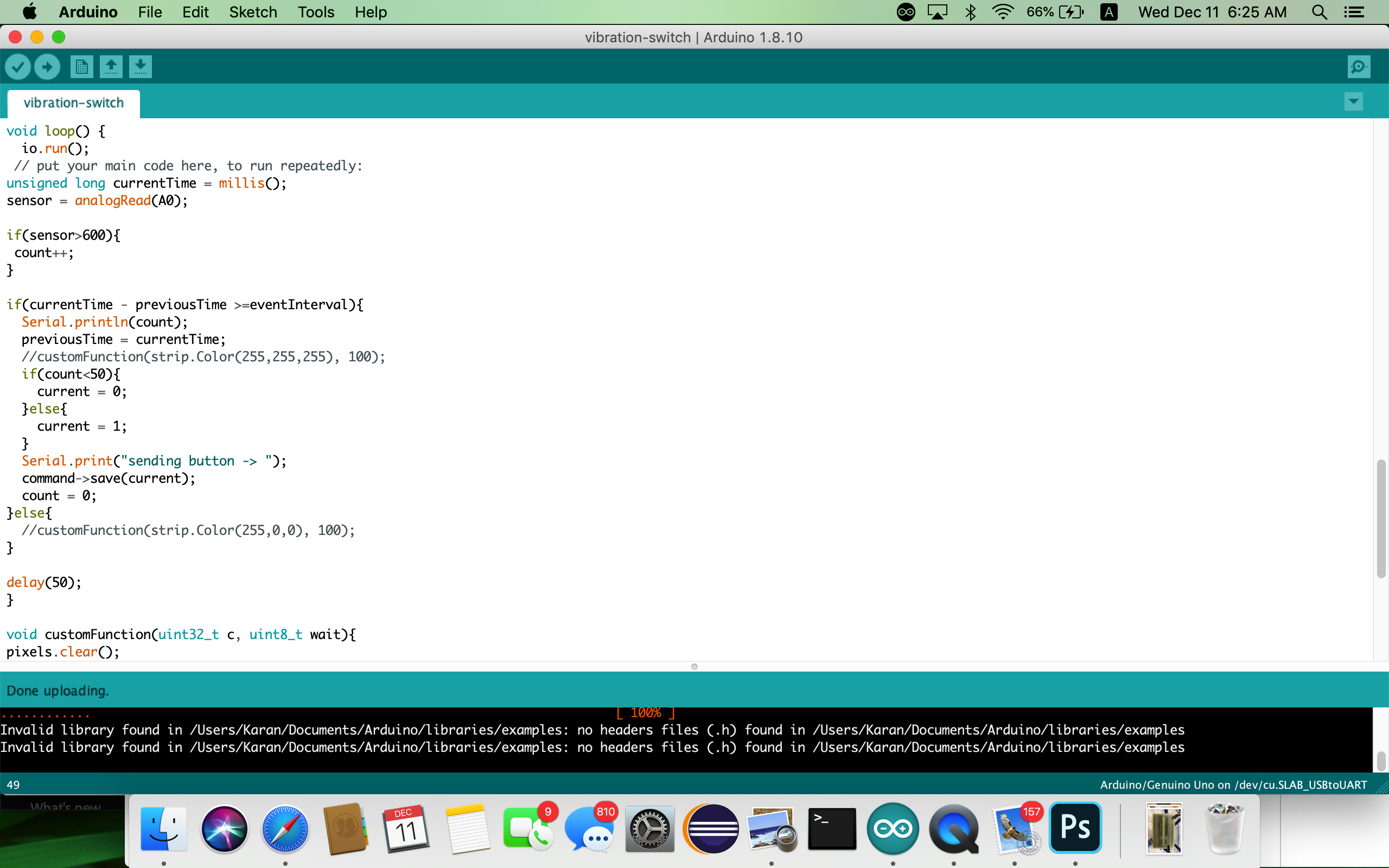
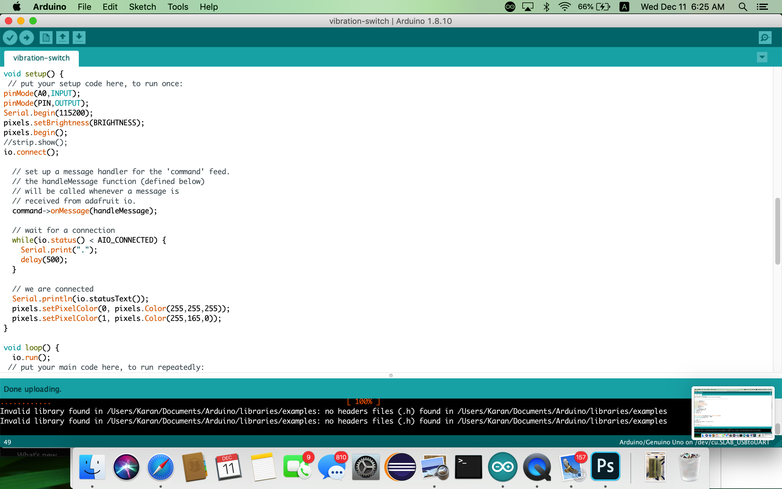
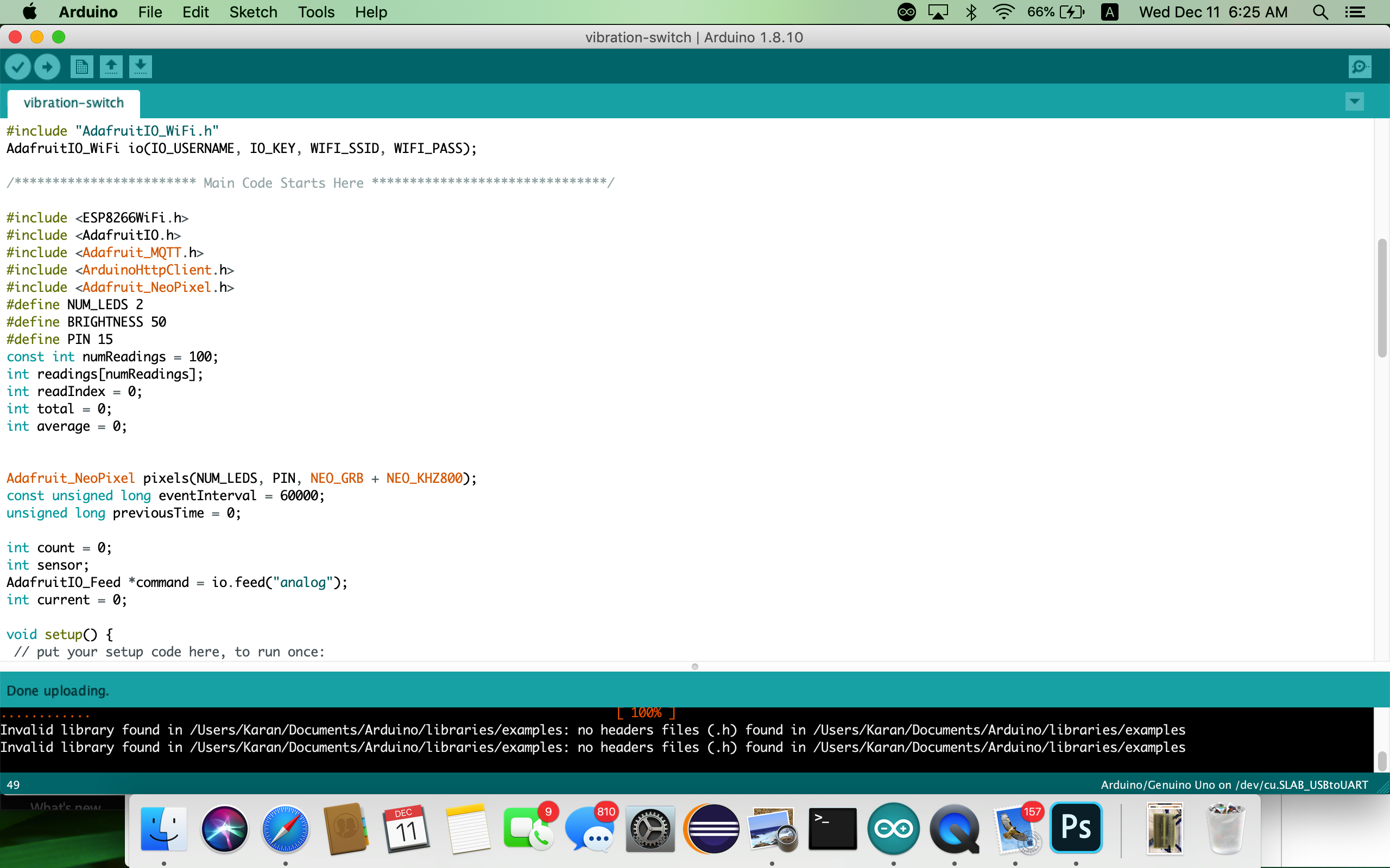
This section is divided into two parts. The first part deals with the internet service AdafruitIO and IFTTT that enable us to perform triggers based on the data we send. The second deals with the code required on the hardware to measure the vibration and light up the neopixel and communicate with the internet service
Part I
Setting up Adafruit IO and IFTTT Applet
You will need to sign up for an account on the Adafruit IO and IFTTT service in order to access them. After signing up, please refer below steps to create the applet.
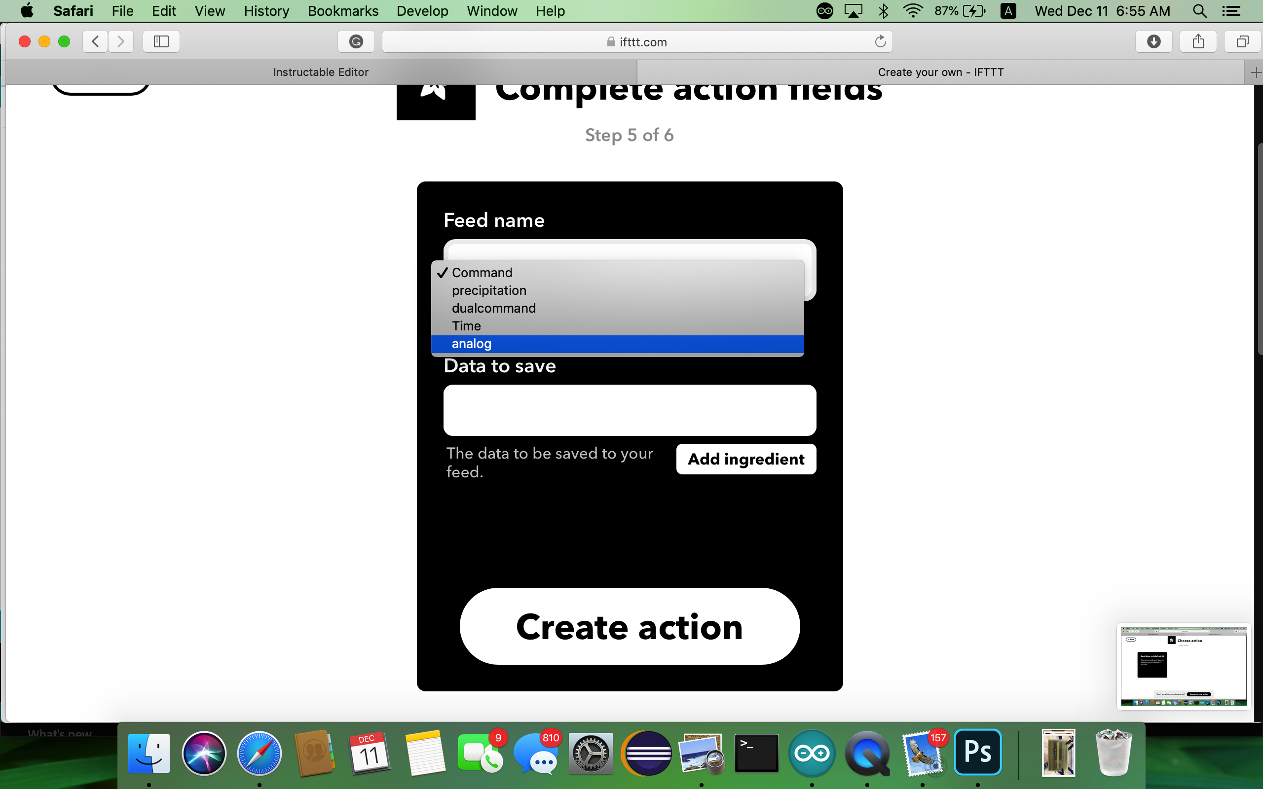
Navigate to Adafruit.IO and create a new feet titled "analog". We will then refer this feed in our Arduino code. Logically, we will be creating an applet where an action happens (vibration is sensed from the sensor). This feed will connect to your Arduino Huzzah board to record the state of brushing. When the brushing state is 0, the Arduino Huzzah will send a message to the Adafruit.IO feed. The information in that feed will then be used in an applet to trigger a tweet. Please make note of the AIO key and account name. It will be used to connect the Huzzah board to the Adafruit service.
Then head over to IFTTT. Under the create new Applet, search for the service Adafruit after pressing the "This" section, then select the option of "Monitor a feed on Adafruit IO". Then select the feed called "Analog" and enter the relationship as equal to and value as 1. Then press Create Trigger.
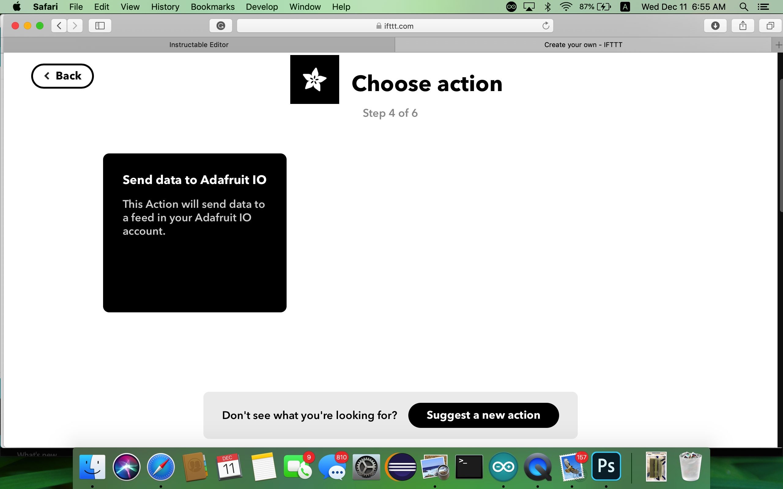
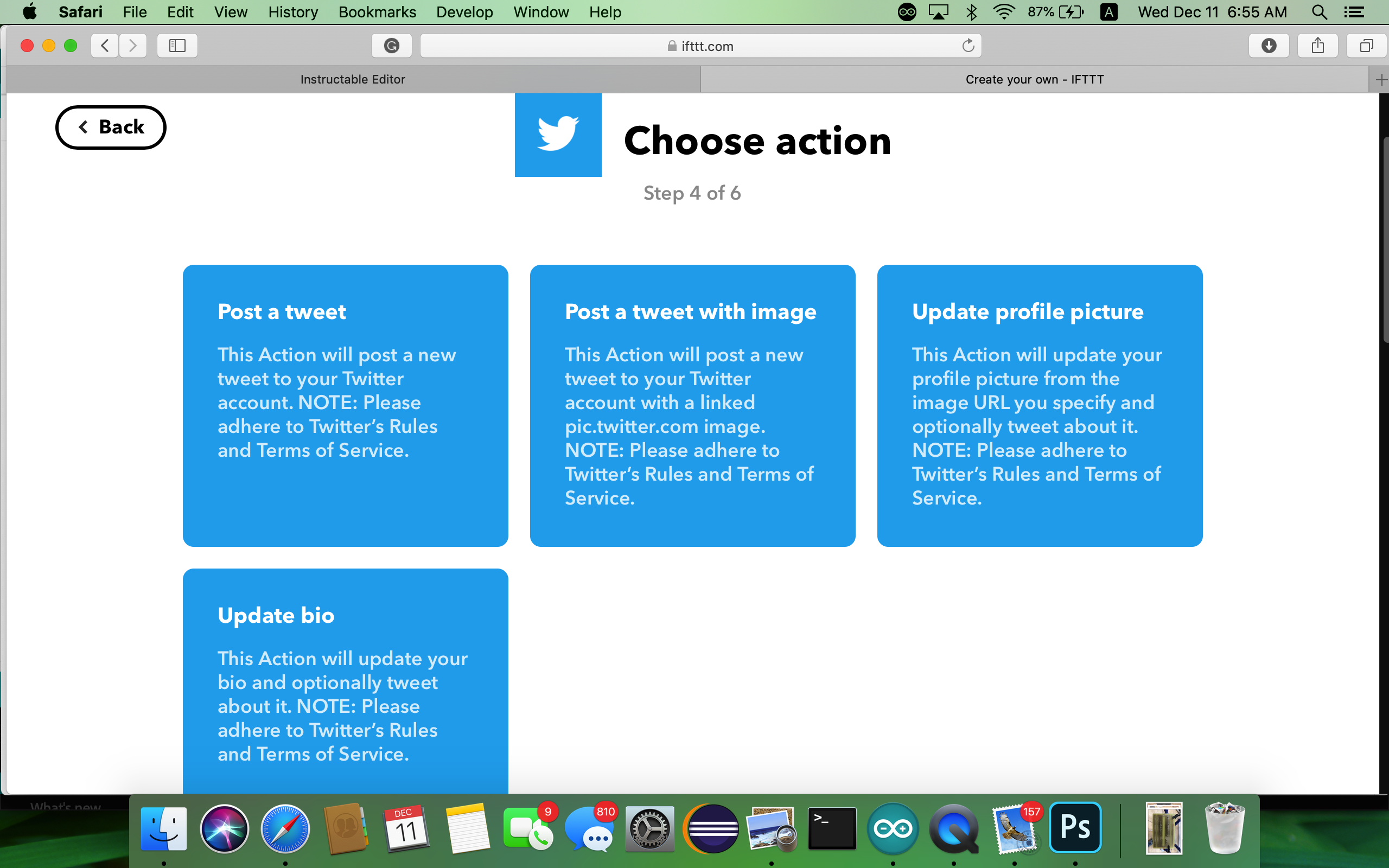
Then head over to the "That" section. Search for twitter, and select Post a tweet with image. It will ask you to connect your account to the service. On proceeding, it will provide you the option of what to tweet and the address of the image to be shared. Upon entering, you have successfully created the Applet and finished Part I of the software setup.
Part II
Arduino Code
In order to get the code working, you will require to download some external libraries. Please refer the set up Arduino tutorial on ESP8266 datasheet.
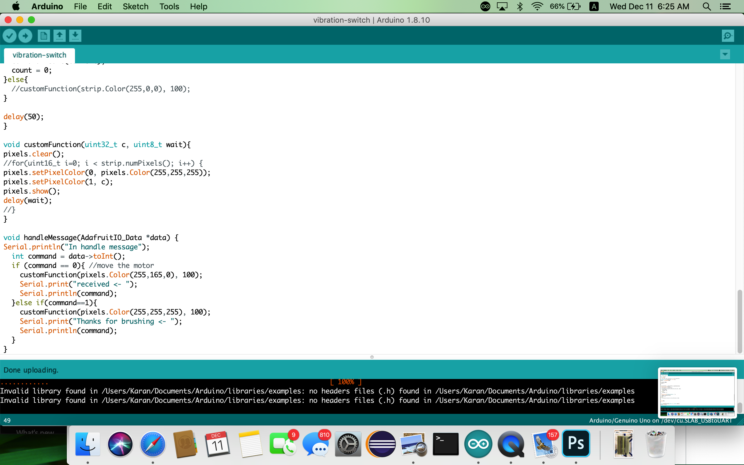
The code mentioned in this will enable us to measure the vibration from the vibration sensor and perform necessary action. The code itself comprises of roughly 3 blocks.
Initialization: In this part, we initialize all the variables and constants and libraries required for the code to execute.
Setup: All the one-time declarations are done in this block.
Loop: All the code that needs to be performed recurringly, each cycle of the controller is put in here.
In the loop section, we are reading the sensor value from pin A0 and if it is greater than a threshold, we are incrementing a variable count by 1. Then periodically within a set interval of 12 hours, we are checking whether the variable count has crossed a value that indicates brushing for 2 minutes. If it has not, then we are sending a corresponding data to Adafruit IO. On receiving the success message feedback from Adafruit, we are changing the color of the neopixel to indicate the user. Please refer comments mentioned in the code for detailed clarifications.
In the end, make sure that the correct board and port are selected in the Arduino IDE. On pressing upload, test the code by going into the serial monitor, it will display prompts that indicate whether the code is successful or not.
Building the 3D Model
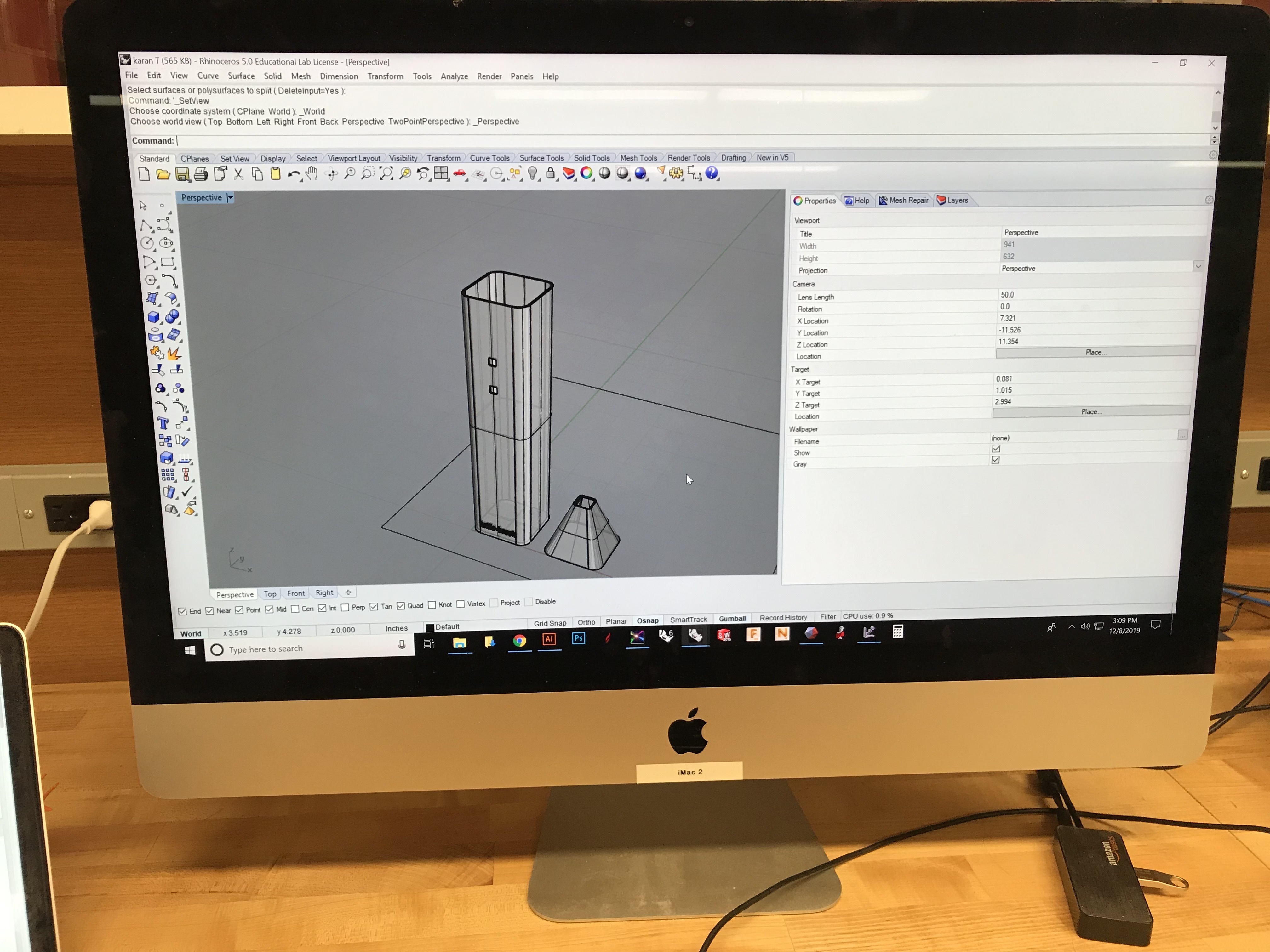
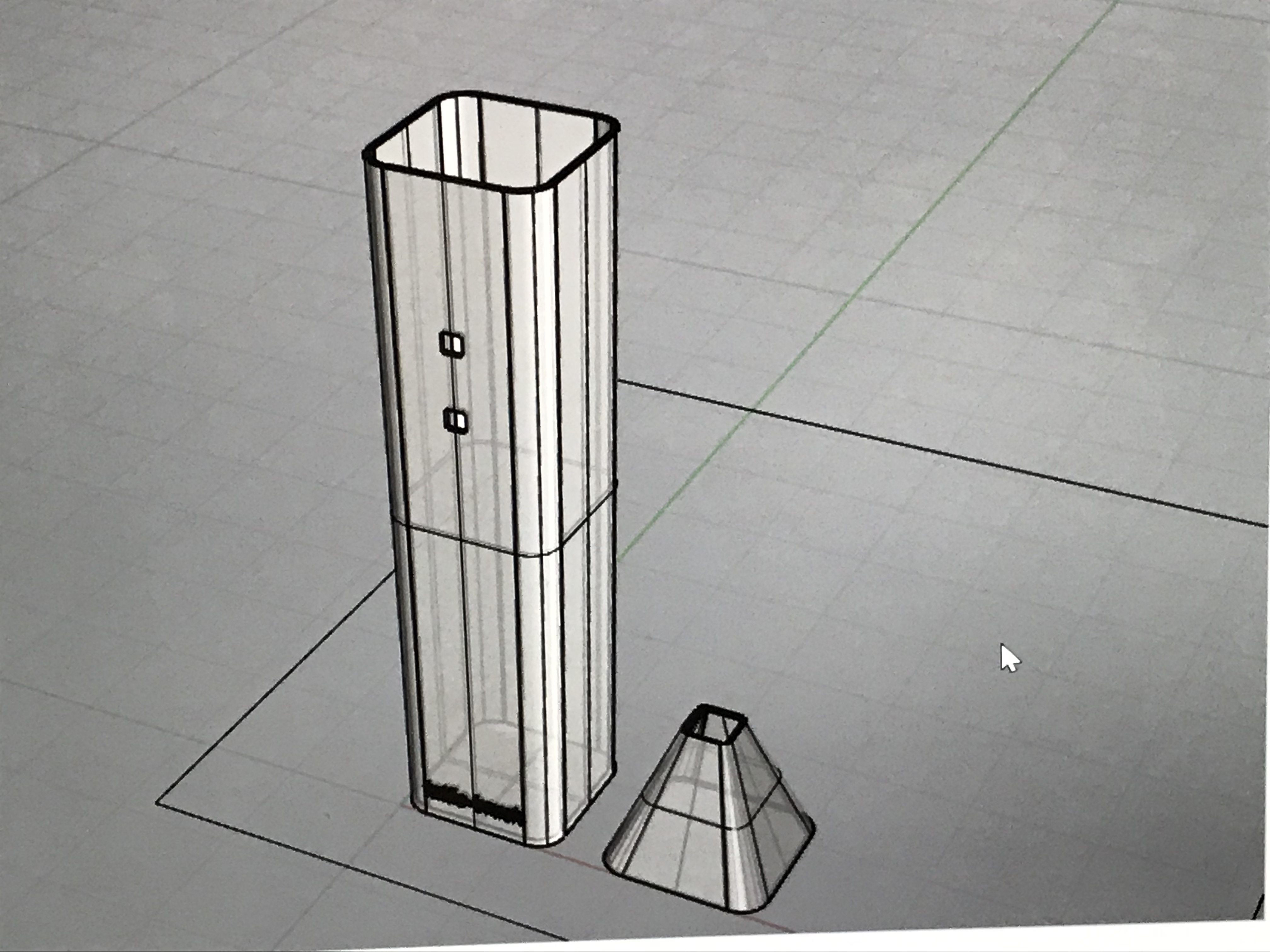
The final step to creating the Tattlebrush is to model and print the brush itself using the 3D modeling software and 3D printer of your choice.
After getting an understanding of the modeling techniques, create two pieces for the outer shell: the body and the top. The body in this tutorial is 5 inches long, 1 inch wide, and 1 inch deep. You can make your body any size and shape that you would like, just ensure that the circuit boards, battery, and sensor can fit comfortably in the shell.
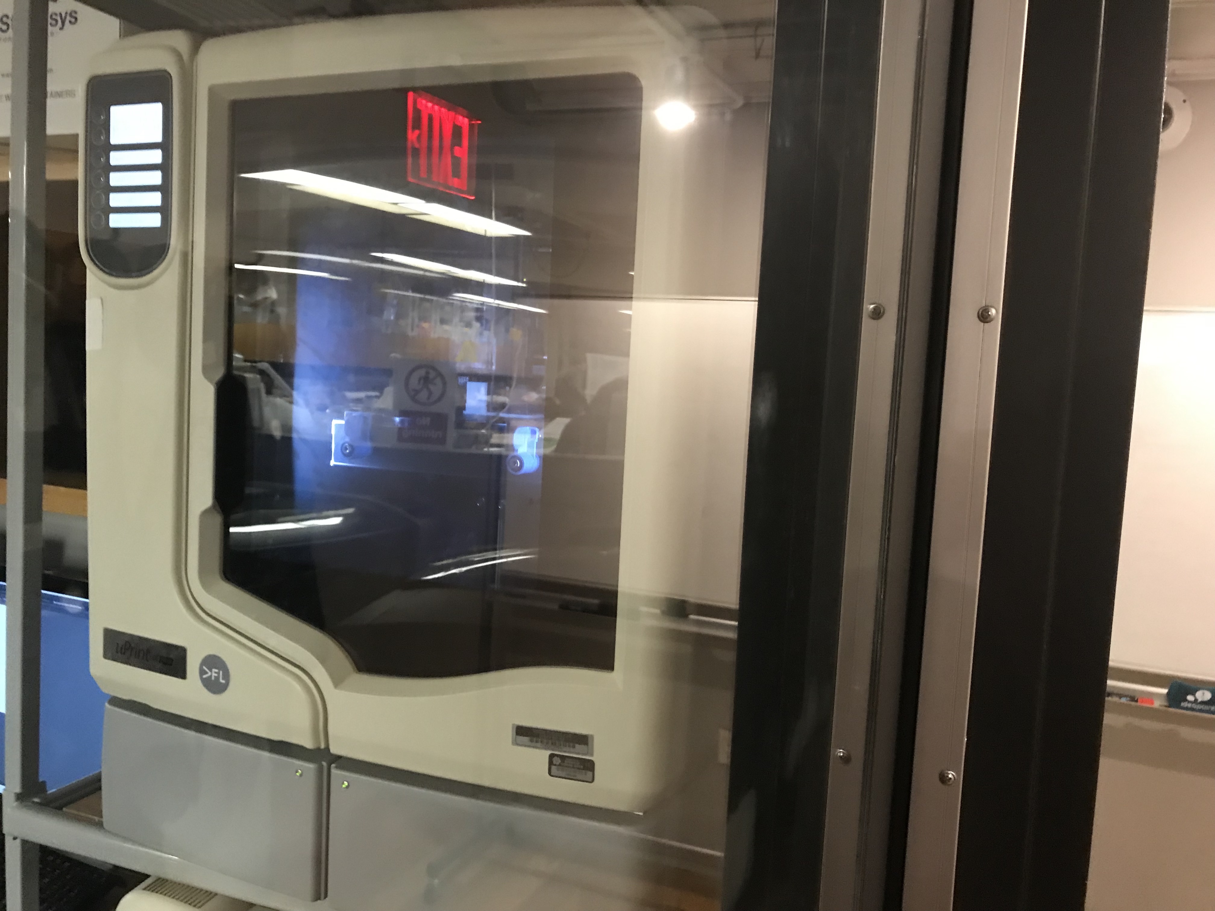
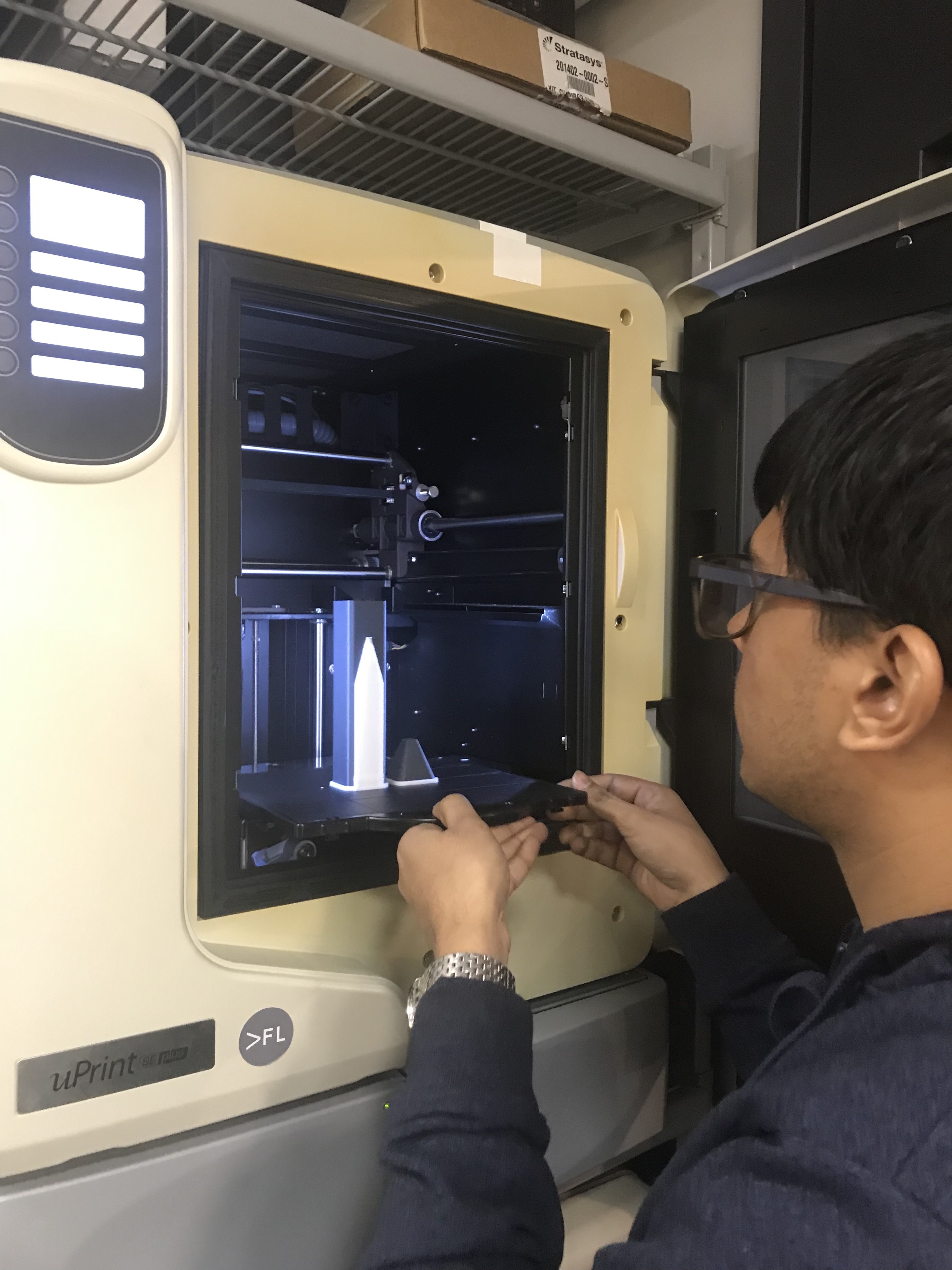
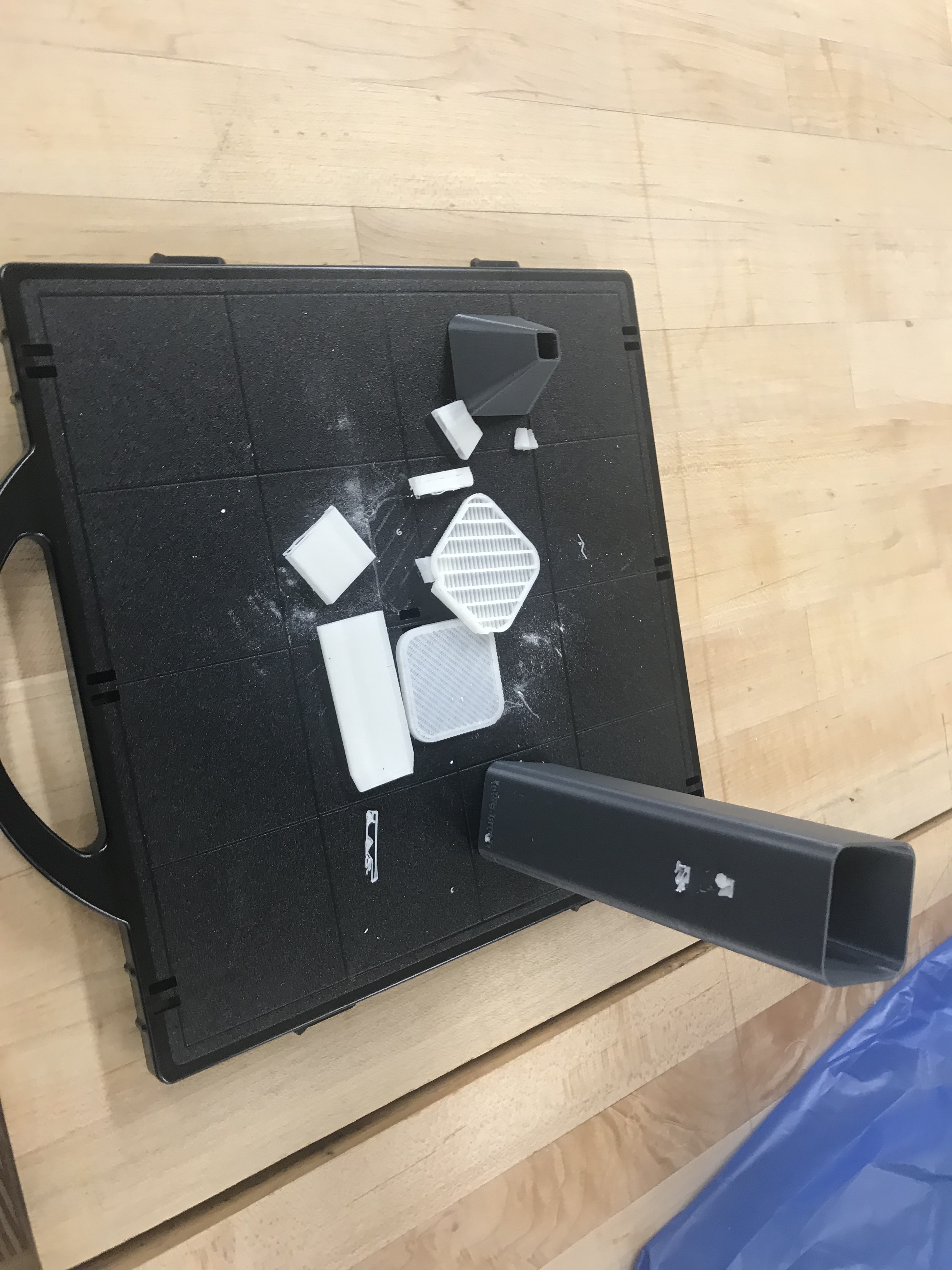
The 3D model was printed using ABS material and print settings used in this model were 0.00001" layer. It took 5 hrs and 17 minutes to print the structure. The support was auto-generated y the software.
Give yourself a treat if you have made it this far. Next up, we will be putting this all together in the assembly section.
Assembly
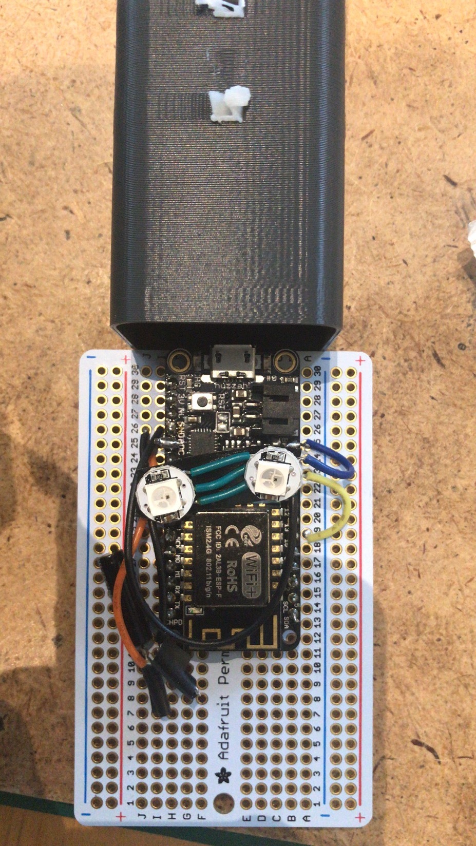
Now that the circuit has been soldered, the applet has been activated, the shell has been printed, and the code has been uploaded, it is time to pull everything together to complete the Tattlebrush.
- Begin by securing the loose end on the circuit with black insulating tape, and cutting the perma-proto board to the section between the positive and negative lines.
- The board will measure around 1.3 inches while the inner housing of the brush is 1".
- You will need to place the circuit in a diagonal way, inserting the vibration end first and then aligning the neopixels in the two holes in the shell.
- The alignment can get trickier. Use wooden tools like chopsticks to put them in place.
- Secure the circuit inside with the help of hot glue or black tape. Ensure that you have padded the inner of the shell so that the actual movement of the hand will not bang the surface making noise every time.
- Then glue a tooth head to the top part of the model. And secure the top part on the bottom base by resting on the side and applying hot glue.