Tablet/Phone As Arduino Screen, and a $2 Oscilloscope
by arpruss in Circuits > Arduino
65962 Views, 119 Favorites, 0 Comments
Tablet/Phone As Arduino Screen, and a $2 Oscilloscope
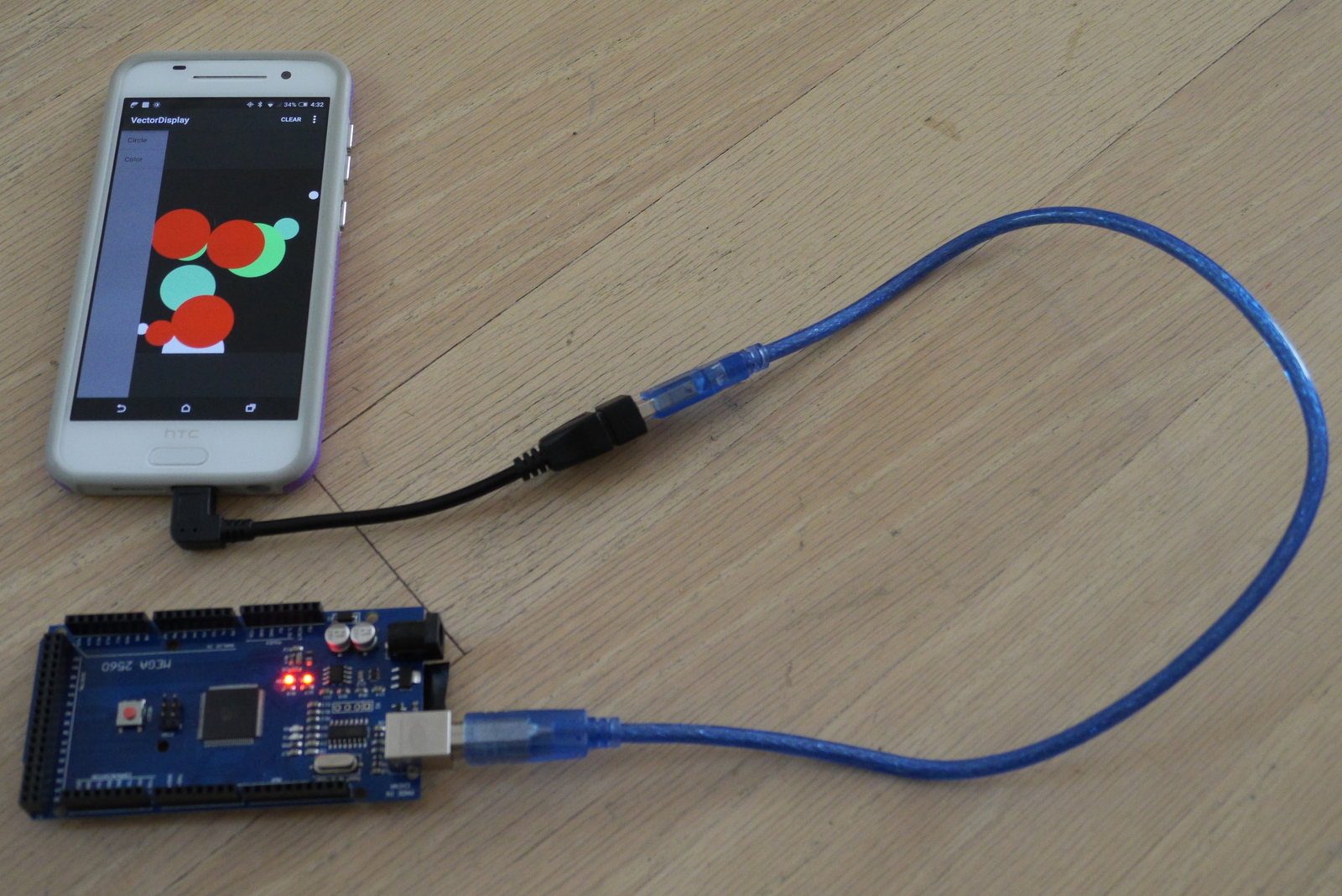
While one can buy a cheap 320x240 LCD touch screen for an Arduino-based project, it can be more convenient--especially for prototyping and testing a sketch--to use a tablet or phone as both a touch screen and a power source for a project. You can have a much higher resolution and better looking display on your Android device (e.g., all your lines will be anti-aliased).
The Android-based screen could be connected via USB Serial, Bluetooth or WiFi (e.g., ESP8266).
To that end I wrote VectorDisplay (source here), an Android app that pairs with an Arduino library that implements a large subset of the Adafruit GFX interface. You can write code that can then be easily ported to use a standalone screen, or keep using the sketch with an Android-based display. And you can send commands from the Android app to control the Arduino sketch. The Arduino library is largely board-independent: it should work with any board that provides a USB serial port object named Serial or with an ESP8266 over WiFi or with Bluetooth (pair your board first).
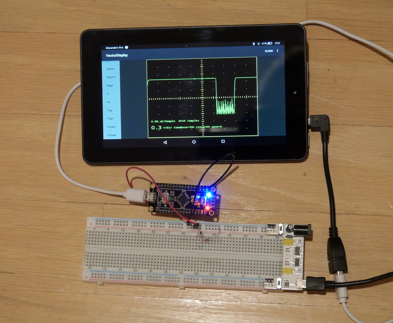
As a proof of concept application, I ported the bare-bones STM32-O-Scope project to use VectorDisplay in place of the ILI9341 display. The result is a (rough around the edges) portable, battery-powered 1.7MS/s oscilloscope that requires nothing more than a $2 STM32F103C board (using the libmaple-based Arduino core), two wires, a USB OTG cable and an Android device. Of course, all you get with this is a range from 0 to about 3.3V.
Install Software
I assume you have an Arduino IDE set up for your favorite board and that your favorite board has a USB serial interface.
Go to Sketch | Include library | Manage libraries. Put "VectorDisplay" in the search area and click on "Install" once it's found.
Download the library zip from here.
Unzip into a folder inside your Arduino/libraries folder.
Download VectorDisplay from Google Play and install it on your Android device. You may need to enable installation from unknown sources on your Android device. The Android app uses the UsbSerial library and the starting point was one of the example apps for the library.
Demo Sketch
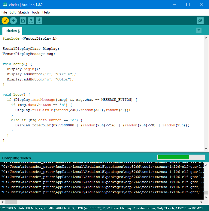

Connect your board (in upload mode if need be) to your computer and go to File | Examples | VectorDisplay | circles in your Arduino IDE. Click on the upload button (right arrow).
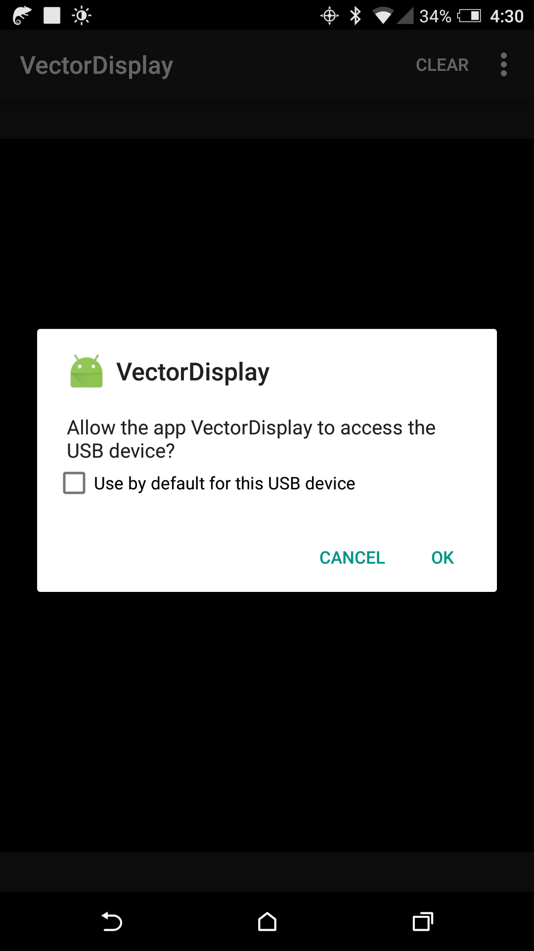
Start the VectorDisplay app on your Android device. Plug your board into the Android device via USB OTG cable. (If your board has a USB micro port, make sure your USB OTG host side goes to the Android device). You should now get a permission query for VectorDisplay. Press OK.
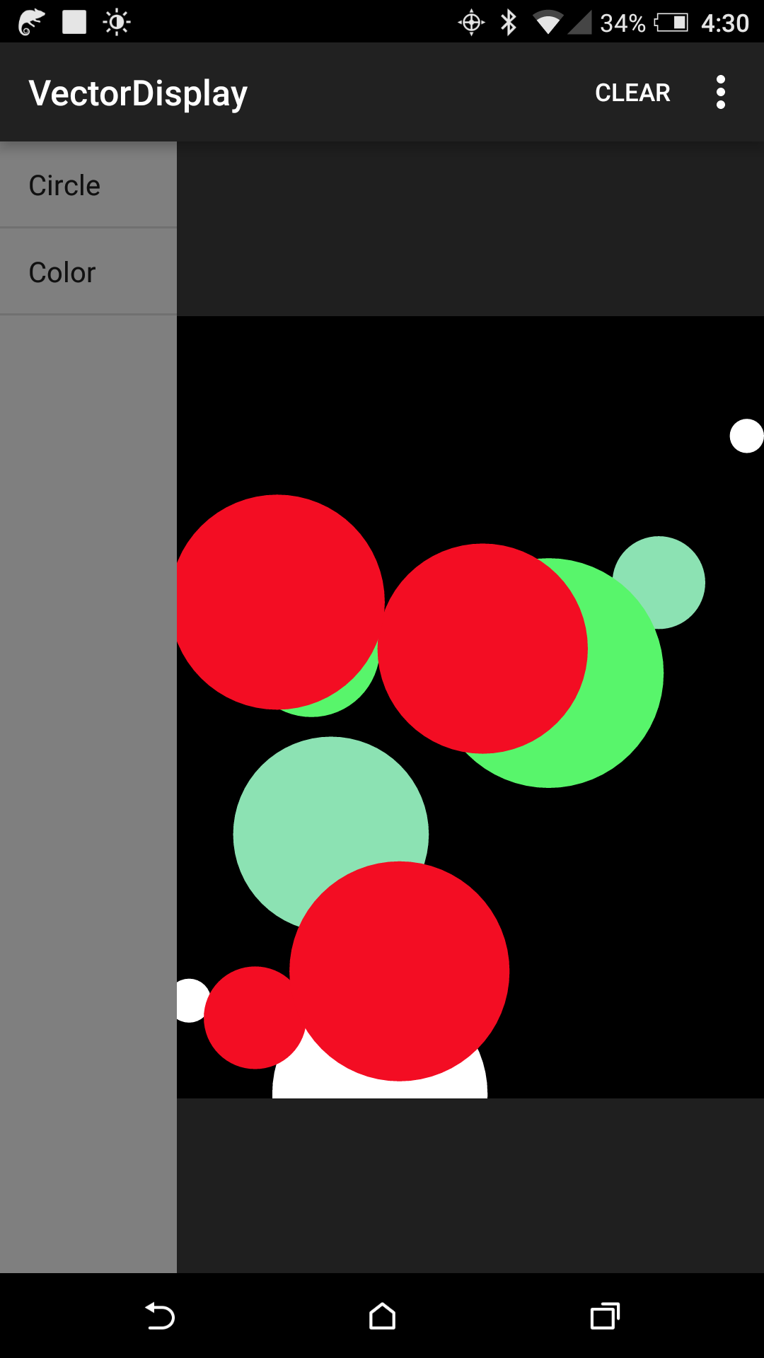
If all goes well, VectorDisplay will now show two buttons on the left side of the screen: Circle and Color. Pressing Circle draws a random circle on the screen and Color changes the color to a random color before the next circle.
If you look at the circles sketch in the IDE, you will see that the serial vector display is declared with:
SerialDisplayClass Display;
and then initialized in setup() with:
Display.begin();
Then command buttons are requested with Display.addButton(). Then loop() calls Display.readMessage() to look for commands being sent via the command buttons.
By default, the coordinate system for the display is 240x320. However, lines and text are all drawn using the full resolution of your Android device screen, with antialiasing for good appearance. That's why the app is called VectorDisplay.
API
The API in the library is in the VectorDisplay.h file. You need to first initialize a Display object. For USB use, do that with:
SerialDisplayClass Display;
Initialize the connection with Display.begin().
There are two sets of methods available in the SerialDisplayClass object: one set uses 32-bit color (including alpha) and commands that are pretty close to the USB serial protocol that my VectorDisplay app uses, and the other set is a subset of the standard Adafruit GFX library methods, using 16-bit color. For the most part you can freely mix the two sets of commands, with the exception that if you use the Adafruit compatible methods, you should use the 16-bit color commands whose names end with 565 instead of the 32-bit ones.
You can set the coordinate system with Display.coordinates(width,height). The default is width=240 and height=320. If you want to emulate a display with non-square pixels, you can use Display.pixelAspectRatio(ratio).
A few of the methods, including pixelAspectRatio(), take a FixedPoint32 argument. This is a 32-bit integer representing a floating point number, where 65536 represents 1.0. To convert a floating point number x to FixedPoint32, do: (FixedPoint32)(65536. * x) (or just TO_FP32(x)).
In addition to being able to send commands from Android buttons, screen touch events are also sent to the MCU.
For WiFi use, see the circles_esp8266 example. You'll need to press the USB button in the app to switch to WiFi mode.
For Bluetooth, you should be able to do:
SerialDisplayClass Display(MyBluetoothSerial);

...
MyBluetoothSerial.begin(115200);
Display.begin();
and then proceed just as in the USB serial case, where MyBluetoothSerial is whatever Stream object (e.g., Serial2) is connected to your Bluetooth adapter.
A $2 Oscilloscope
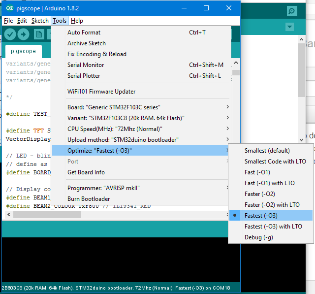
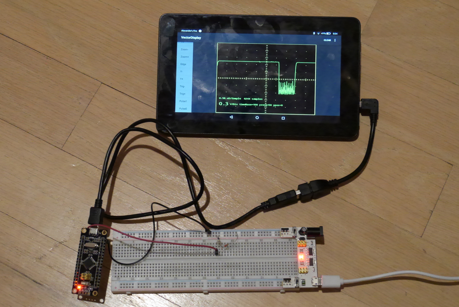
For the quick and dirty oscilloscope, you will need a blue or black (easier to deal with) pill STM32F103C8 board, which you can get on Aliexpress for under $2. I describe how to prepare the board for use with the Arduino environment for it and install sketches here.
Download this sketch on the board, which is a modified version of Pingumacpenguin's STM32-O-Scope sketch. Edit the #define BOARD_LED line to match your board. I am using a black pill whose LED is PB12. The blue pills (and some black pills that has the same pinout as the blue pill) have the LED at PC13.
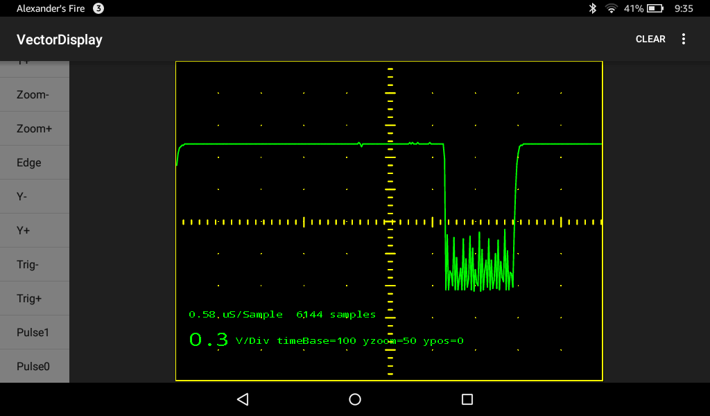
Connect one wire--ground probe--to the board's ground and another wire to the board's B0 pin. Plug the board into an Android device with VectorDisplay running, and you have a portable, battery powered oscilloscope.
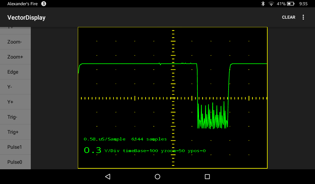
In the photo I have the oscilloscope hooked up to a phototransistor. The trace on the screen is from a TV infrared remote control.