TV Back Light
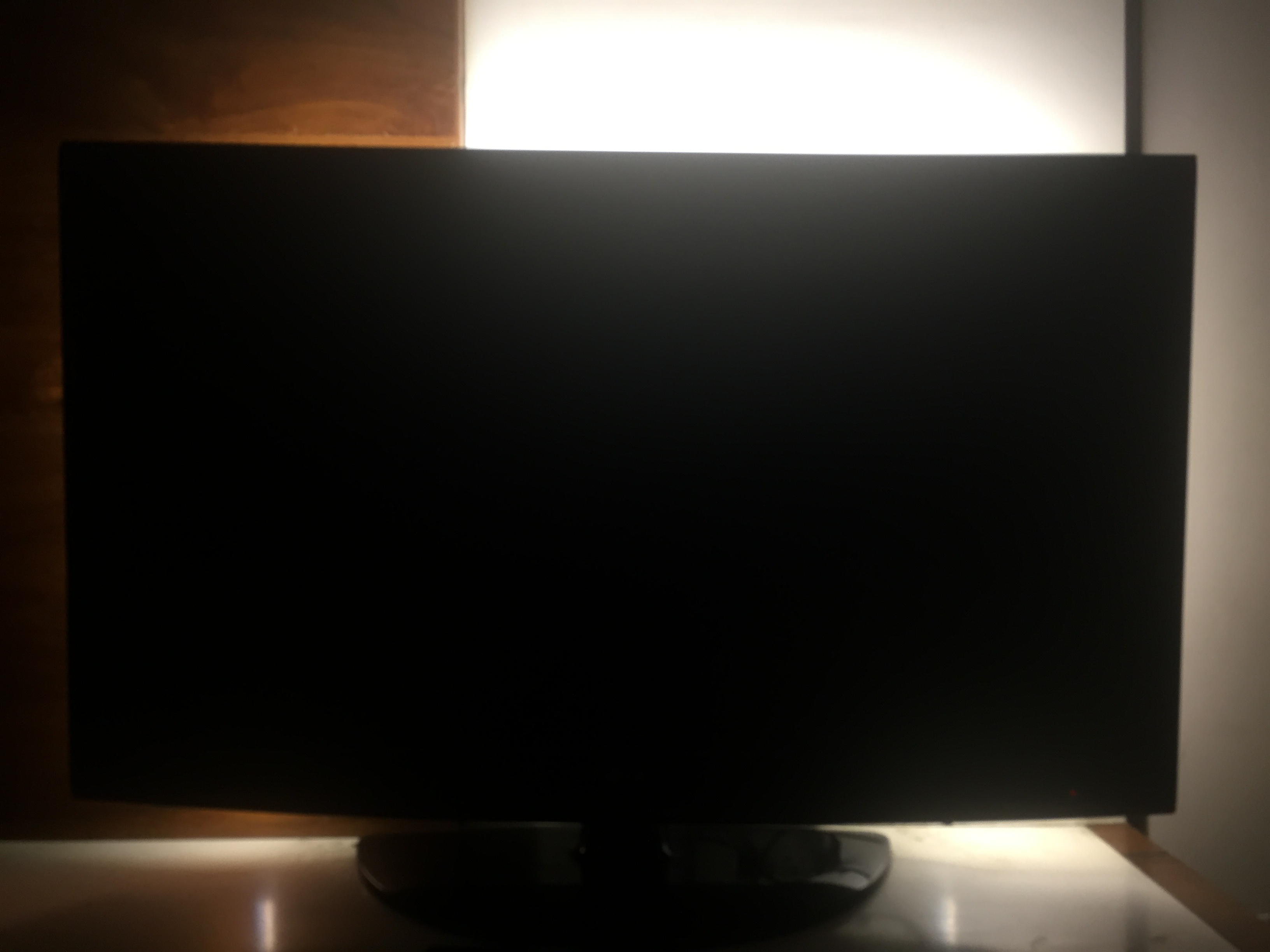
In this project I will show you how to control the back light of your tv using your tv remote.
Supplies
This project requires the following components:-
1. An Arduino or an Atmega 328p
2. 2 x 10k resistor( 3 for stand alone version)
3. 2 x MOSFET (I used the IRF 540)
4. Ir receiver (VS 1838)
5. 16 MHz crystal(For standalone version)
6. 2 x 22pF ceramic capacitor (For standalone version)
7. 100nf Ceramic capacitor (2 for standalone version)
8. 12V 2 amp power supply
9. 470nf capacitor (For standalone version)
10. FTDI Programmer (If using Arduino pro mini)
Prepare the Micocontroller
If using Arduino board follow the following instruction:-
1. Place the IR receiver on a breadboard and connect vcc to +5V of Arduino, GND to GND of arduino and out to pin D3 of the Arduino
2. Plug the Arduino to your computer and open Arduino IDE
3. Download the IRremote library by Click Here
4. Upload the code given Below and open the serial monitor
5. Using your TV remote Press the button you want to assign to turn on and off, change the brightness and temperature of the led.
6. On the serial monitor there will appear HEX values note them and write that which value is for which button
if using the standalone version follow the following instruction:-
1. plug the microcontroller in the breadboard, along with the resonator, the voltage regulator, IR receiver.
2. connect a FTDI programmer to the microcontroller.
3. follow step 3 in from above.
Downloads
Program the Microcontroller
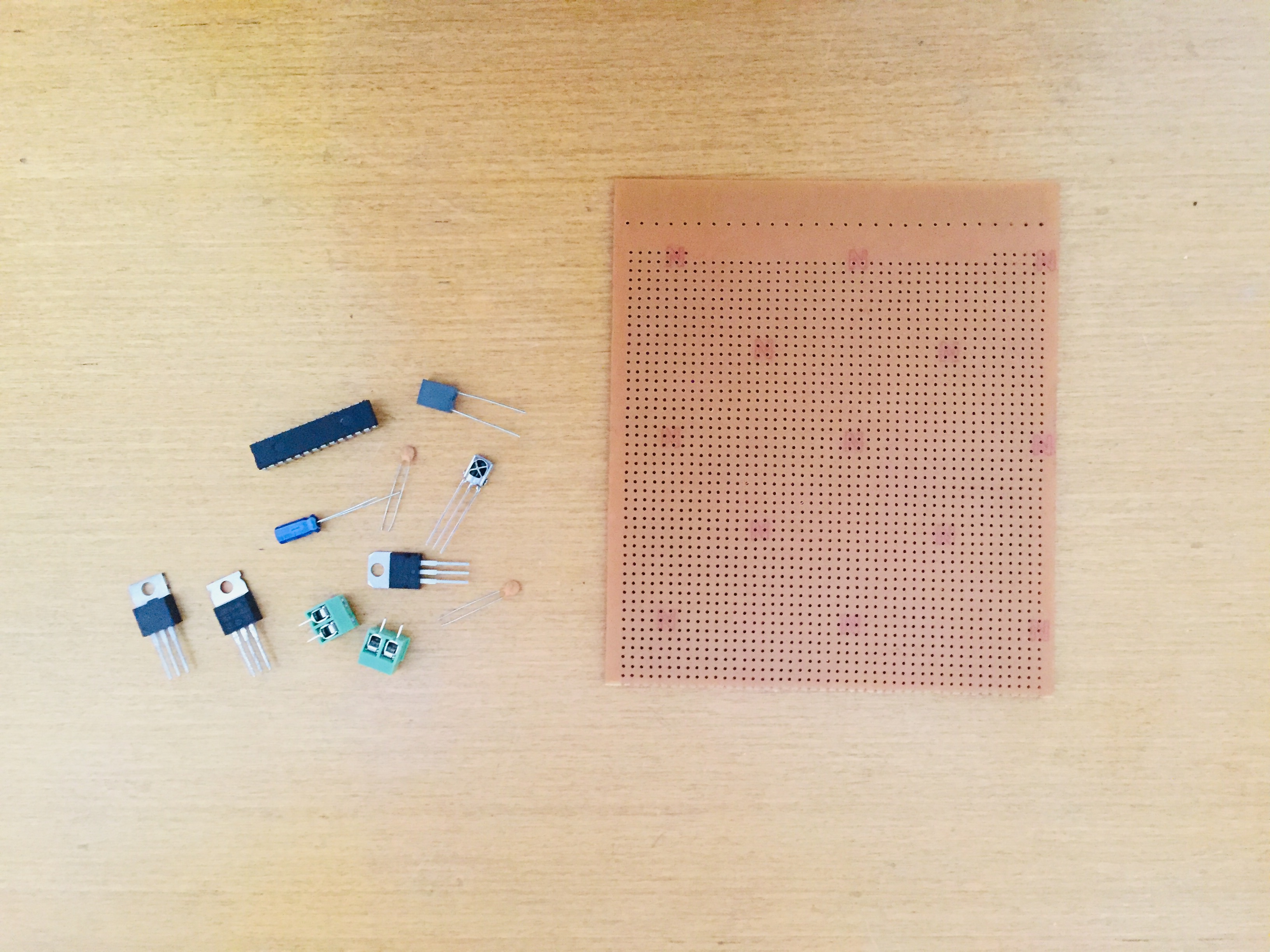
Upload the given code and changes remote hex code from the ones you noted before , with that being said the software part is complete and its time for the hardware.
Downloads
Build the Circuit
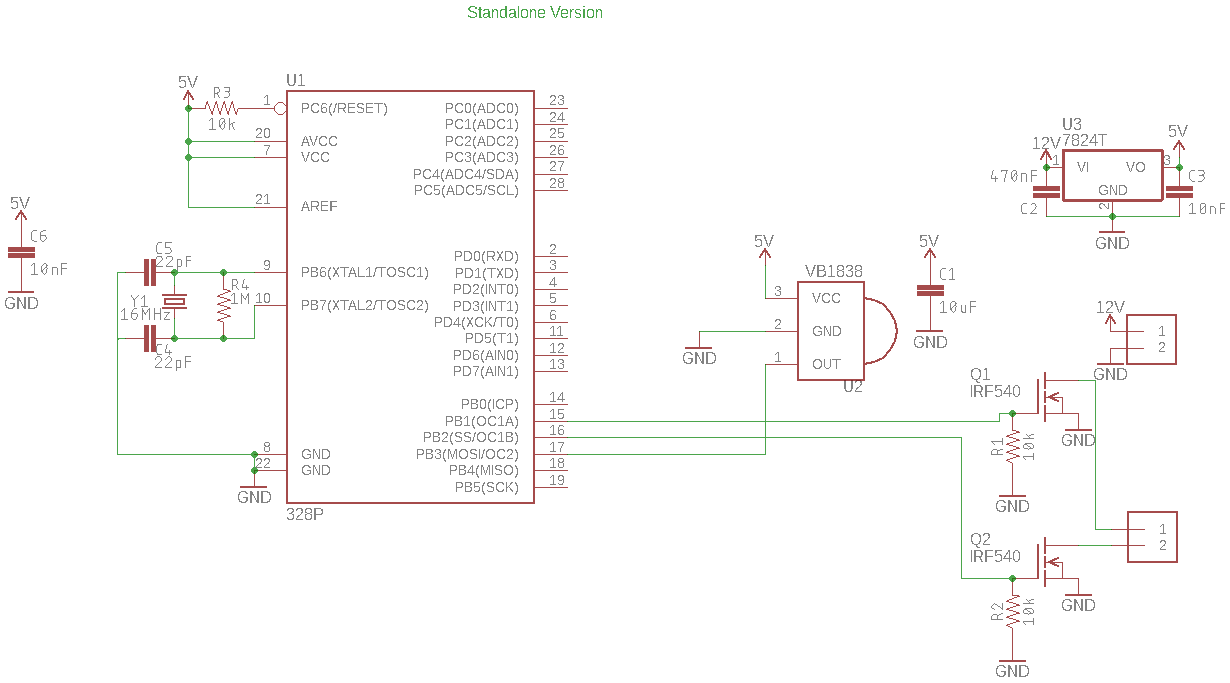
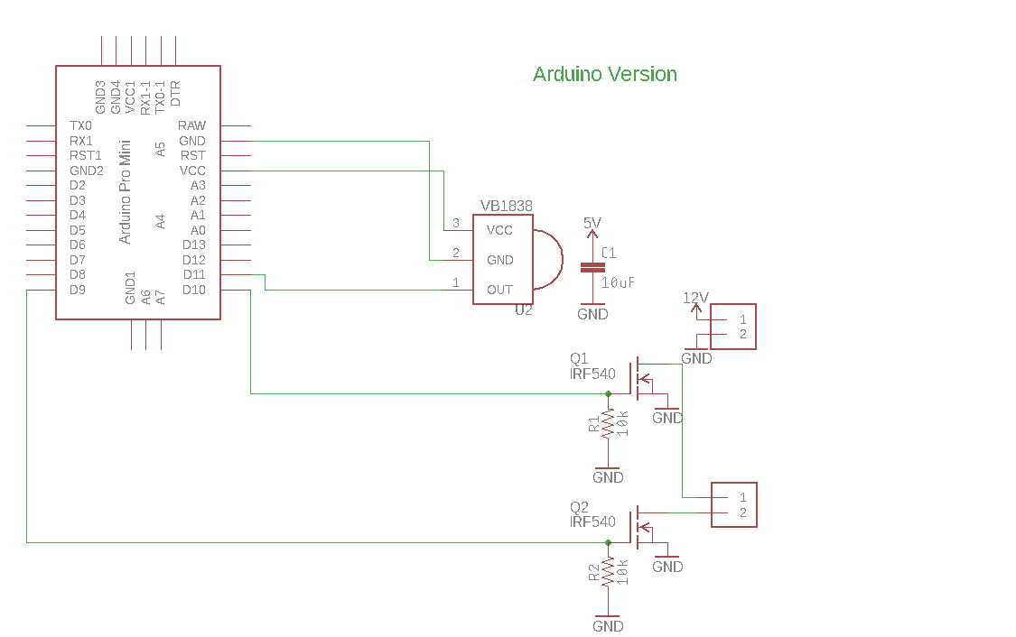
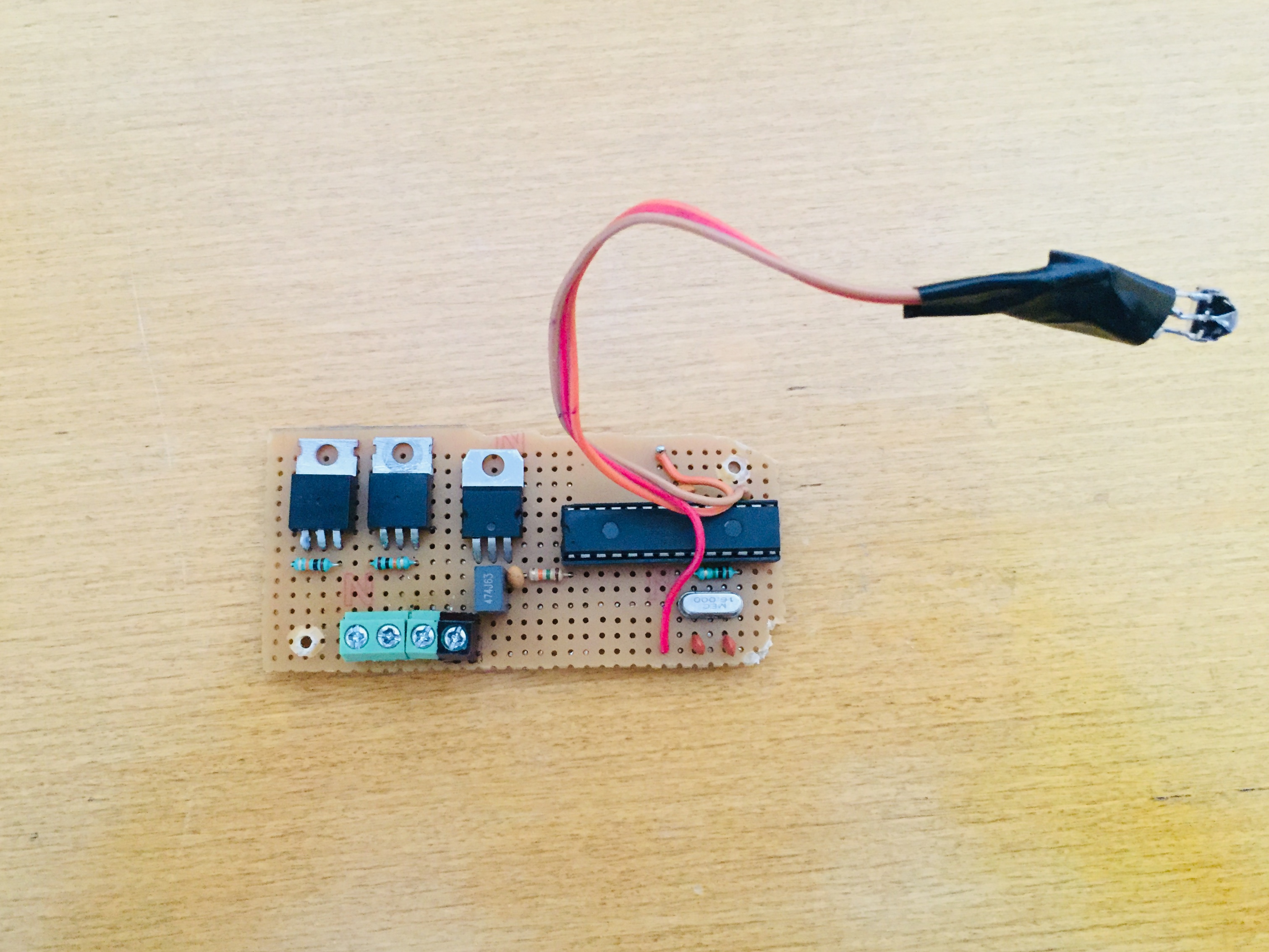
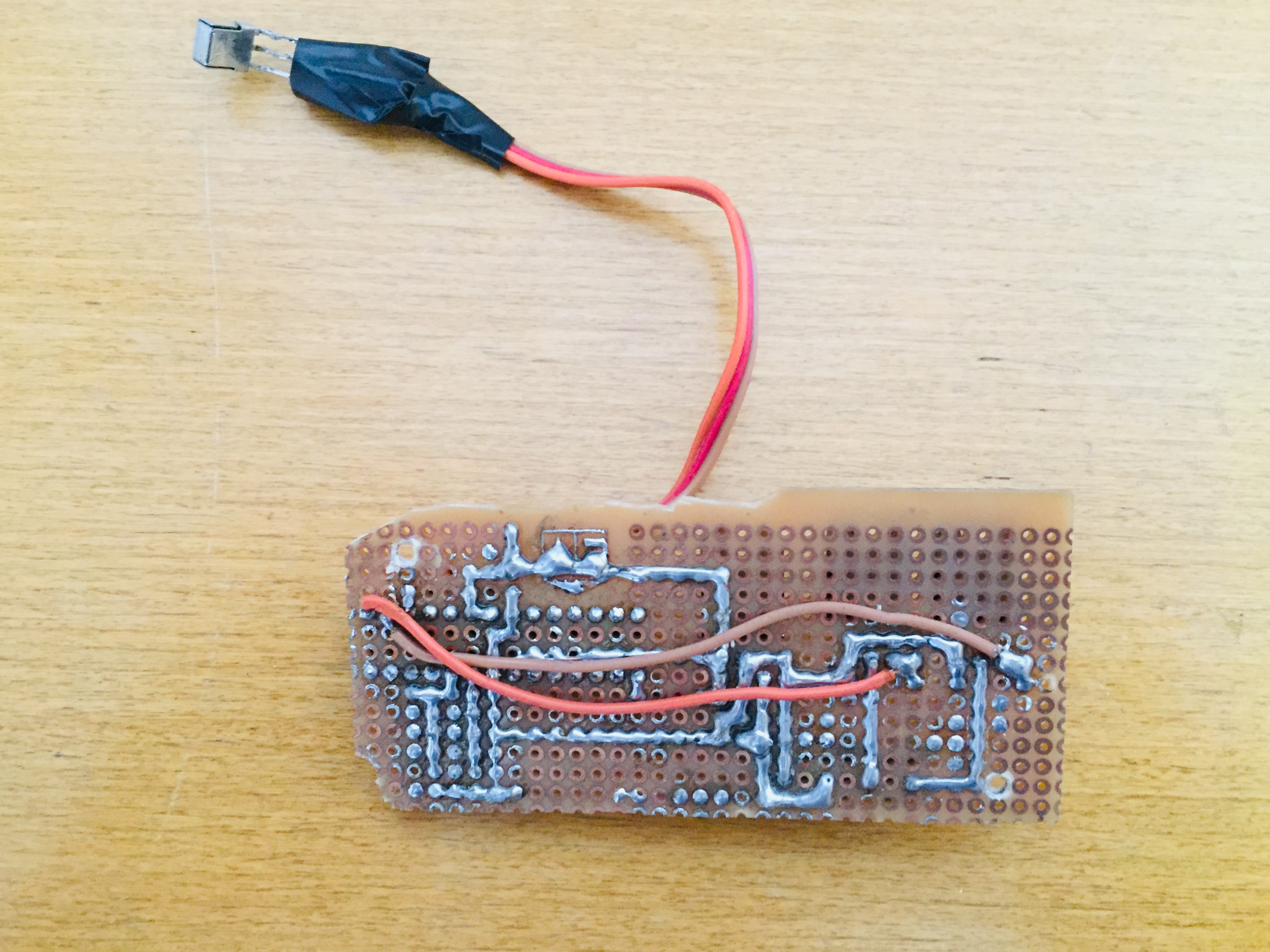
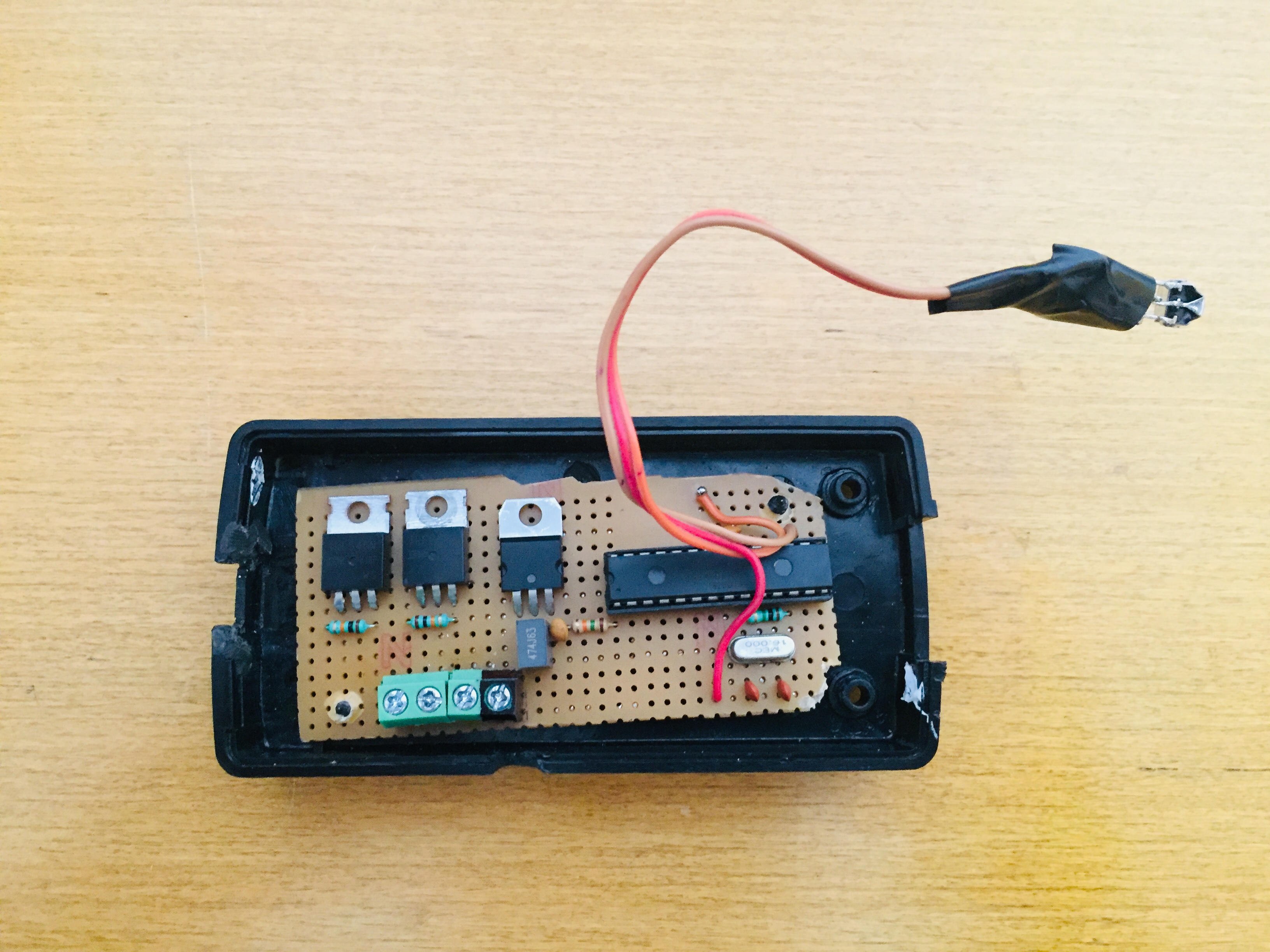
On a piece of perfboard place the components in a desirable manner and connect them using copper wire and solder bridges. Here are a couple of photos of my circuit with the schematic, one for the Arduino and one for the standalone version.
The circuit includes a microcontroller and a IR receiver the receiver senses the signal of the tv remote and provide it for the microcontroller to process the microcontroller then generates a PWM signal to control the gate of 2 MOSFET that finally control the brightness of the led.
Then there are pull down resistor for the gate of MOSFET to prevent latch ups ,pull up resistor for the microcontroller reset pin , a 16 MHz resonator and finally a 5 volt regulator with smoothing capacitor to power the control electronics.
Instrall the LEDs
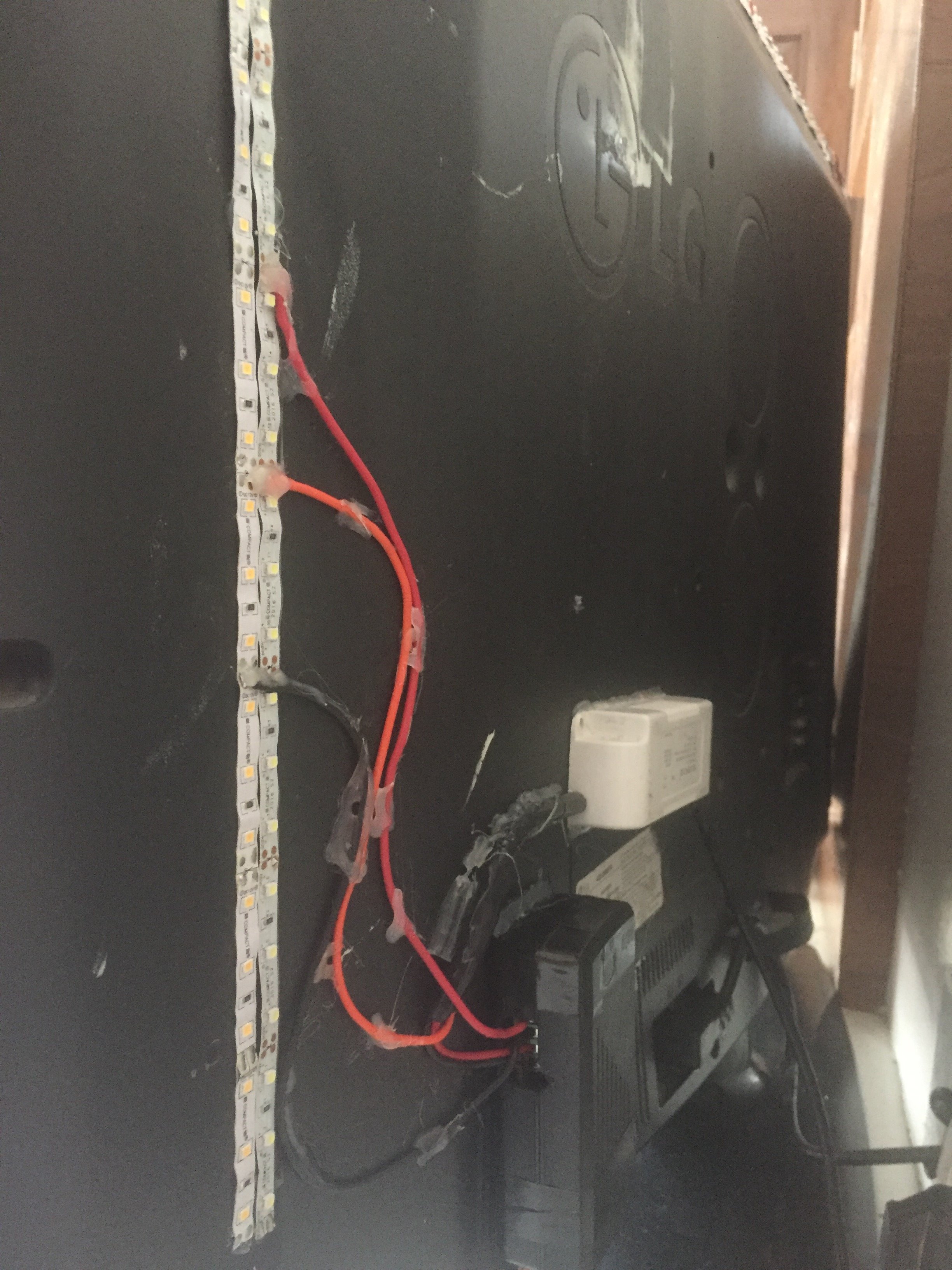
Using the adhesive tape on the back of the cold and warm white led strip stick them at the back to your TV. then using solder connect the anode (or +ve terminal) of the both the led to each other in order to create a common anode and then connect the common anode to the +ve terminal of your power supply. The cathode (or -ve terminal) of the each LED connect to drain of two MOSFETS .
Success !!
so its finally complete and you can control the led without getting out of bed. Now if it does not work for you then the comment section is always open. Also I m not that good of a programmer of if any one of you can improve th code please share it with us.