TDS Water Quality Sensor by Group 1
by Dorairaj in Circuits > Microcontrollers
452 Views, 0 Favorites, 0 Comments
TDS Water Quality Sensor by Group 1
In the quest for safeguarding the pristine waters of Tasik Kenyir, an advanced water quality monitoring system has been deployed, integrating the capabilities of the ESP32 microcontroller and a Total Dissolved Solids (TDS) sensor. This IoT-driven solution not only detects anomalies in real-time but also enhances user accessibility through a Node-RED dashboard, fostering environmental awareness and contributing to the preservation of a balanced ecosystem for marine creatures. In this system, we use ESP32 microcontroller, TDS sensor, powerbank, LED, breadboard, usb to micro usb cable. As a result, the monitoring on the water quality level is monitored from time to time and any drastic changes will require user to have a visit too the actual site.
Supplies
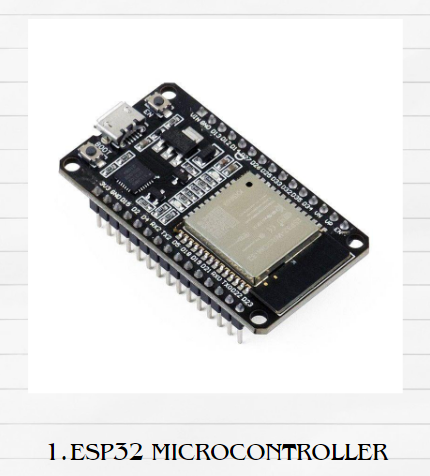
- ESP32 Microcontroller
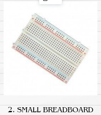
- Small Breadboard
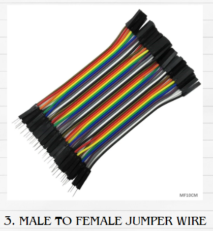
- Male to female jumper wire
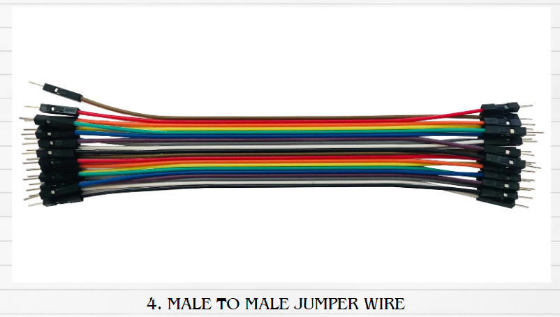
- Male to male jumper wire
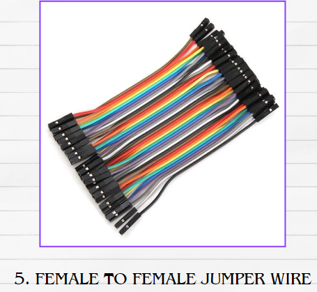
- Female to female jumper wire
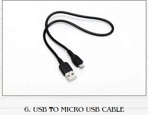
- USB to Micro USB cable
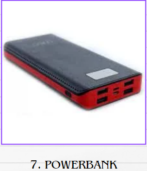
- Powerbank
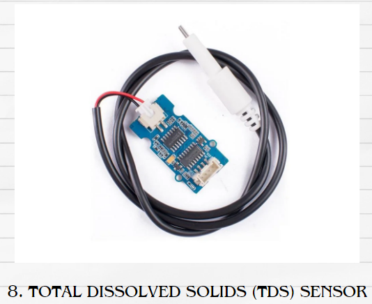
- Total Dissolved Solids (TDS) sensor
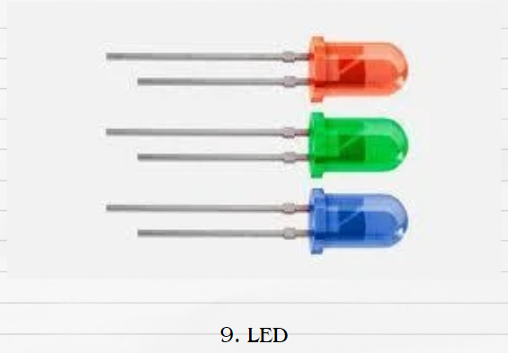
- LED
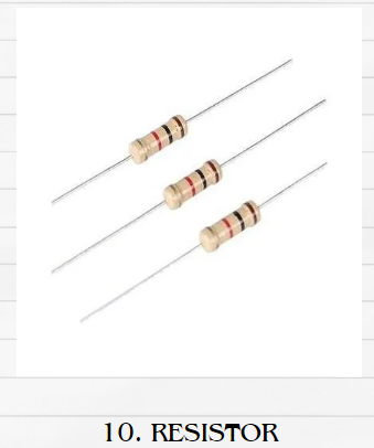
- Resistor
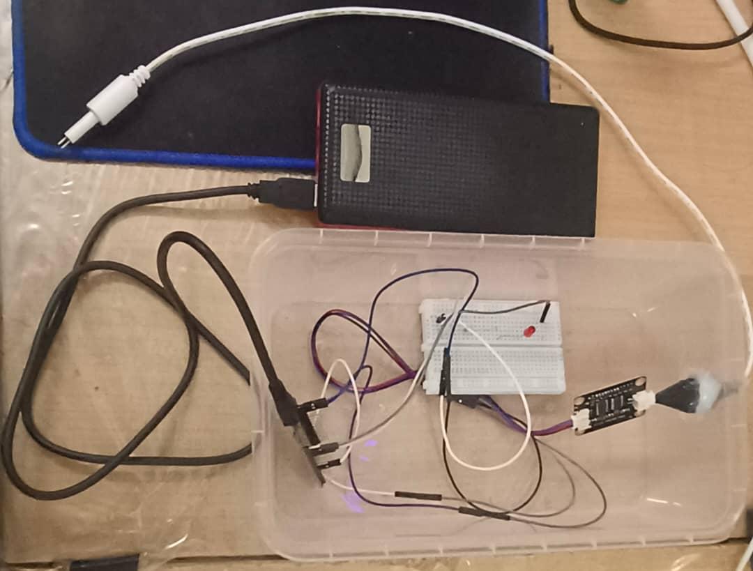
Setup Circuit

- One male to male jumper wire from TDS sensor connects to female to female jumper wire that connects to D33 (ESP32).
- One male to male jumper wire from TDS sensor connects to female to female jumper wire that connects to 3V3 (ESP32).
- One male to male jumper wire from TDS sensor connects to female to female jumper wire that connects to GND (ESP32).
- Connect LED to breadboard using (ESP32).
- Connect cathode from LED with male to female jumper wire and connect to GND (ESP32).
- Connect anode from LED to resistor then connect male to male jumper wire with female to female jumper wire that connect to D13 (ESP32).
- Connect the ESP32 to powerbank using USB to MicroUSB cable.
*Note please set up the circuit according to the project requirement based on the environment.
Setup MyMQTT
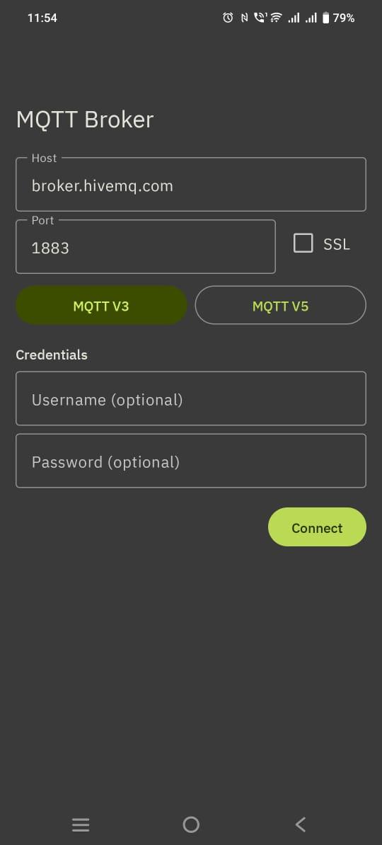
- Install MyMQTT app in playstore or appstore.
- Click on the MyMQTT app.
- Select MQTT V3.
- Then click connect.
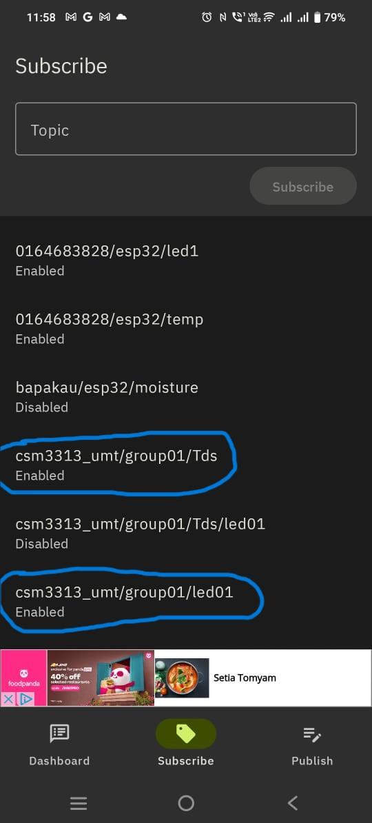
- Click on subscribe section.
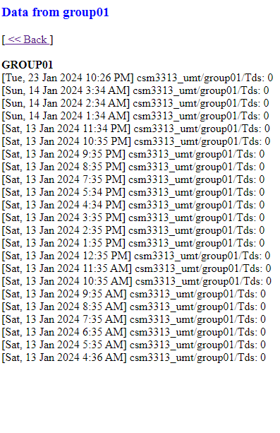
- Type csm3313_umt/group01/Tds at the topic box and click subscribe.
- Repeat step 6 with this topic csm3313_umt/group01/led01
Setup Node Red Dashboard
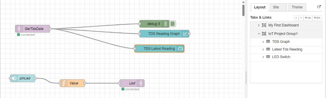
For Total Dissolved Solids(TDS) dashboard
1. Open node red
2. Add MQTT In node and double click to change the name.
3. Add debug node, chart node and gauge node.
4. You can double click and change the name at the edit node.
5.After that, click button Done.
6. Connect the debug node, chart node and gauge node to MQTT In
For LED
1. Add Switch node
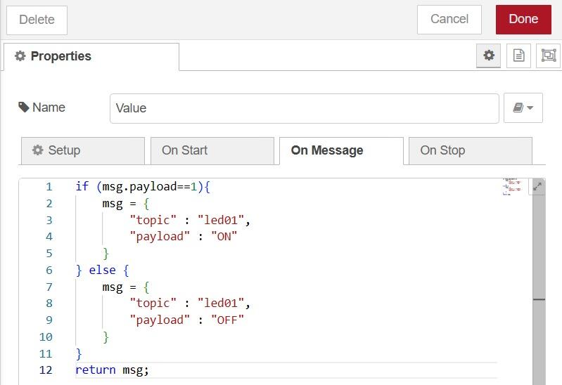
2. Add Function node
* this is the code for LED
3. Add MQTT Out node
4. After that, connect the switch node to the function node.
5. Then, connect the function node to the MQTT Out.
6. After that, click button Deploy at the right above.
Coding for TDS Water Quality Sensor
Downloads
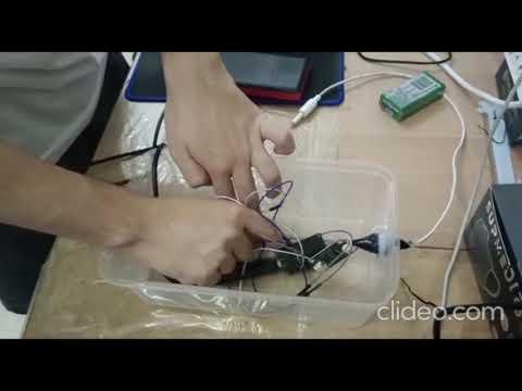
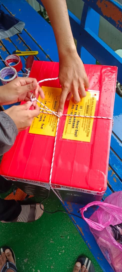
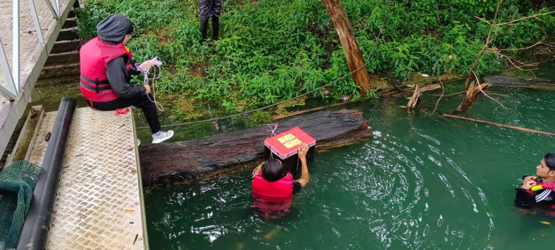
Prepare & Deploy the Circuit
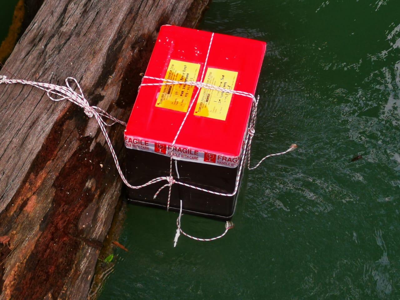
Monitoring the Sensor