TAM 335 Lab 5

The purpose for this instructable is to explain the calibration methods for the flowmeters used in the lab. Steps 1-4 pertain to the calibration of the machines while Steps 5-8 pertain to the data acquisition.
Prior to calibration, it is necessary perform a few safety steps. Check that the discharge valve is closed, and the levels of mercury in the mercury-water manometer. The manometer must be checked for the hydraulic flowmeter. If the levels are not equal you can equal them by opening and closing the two manometer drain values, to allow for trapped air to escape from the drain valves. Check that the central scale gives a zero reading, and adjust accordingly.
Zero the Transducer

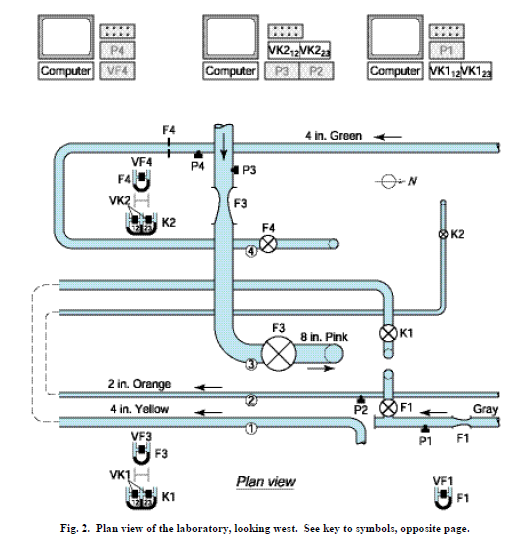
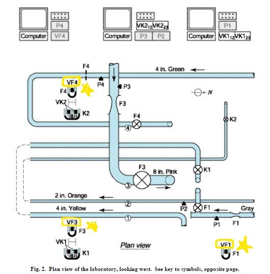
Begin by zeroing the transducer output on the Validyne differential pressure transducer, labeled VFn interface box. This device is located next to the computer.
Open Manometer Bleed Valve and Collect Data
Open the manometer bleed valve labeled ‘CAL VALVE’ to reduce any artificial pressure buildup that has occurred in one of the manometer lines, while keeping the discharge valve closed. At the same time, record the reading given by the transducer output (in volts) and the manometer levels (in cm). The LABVIEW software is used to obtain the results. There should be 5 data points collected that span from zero pressure to the maximum pressure difference possible with the bleed valve fully open.
Check the Output
Check that the output of the VFn is not more than 10V. If the output is more than 10V you will need to repeat the calibration to ensure the A/D board will read the voltages correctly.
Close the 'CAL VALVE'
Close the ‘CAL VALVE’. The LABVIEW program will perform a linear least-squares analysis on the data as it is collected, for determining the accuracy precision of the data later in the analysis.
Check the Gain Adjust Control

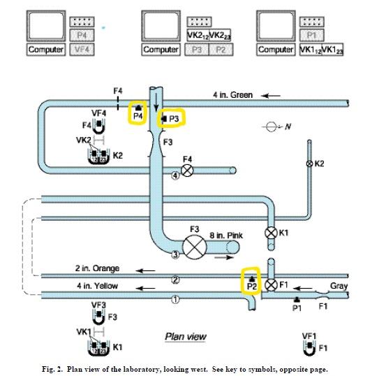
After calibrating the flowmeters, prepare for data acquisition. Locate Pn in Figure two. This is the Gain Adjust control of the paddlewheel flowmeter. Check that this is set to 6.25 turns for P1 and P4, and is set to 3.00 turns for P3.
Zero the Paddlewheel Flowmeter Output
Zero the paddlewheel flowmeter output by using zero adjust control.
Open the Discharge Valve
The final step is to open the discharge value until the allowable manometer deflection is reached, or until it is fully open. Pay attention the VFn readings as well as the Signet paddlewheel voltage readings. When the Signet paddlwheel voltage is large and nonzero, record both values.
Data Collection
When the pipes have reached their maximum flow rate, the paddlewheel flowmeter readings and manometer readings should be recorded. Take a weight time measurement. With the LABVIEW software, record the time-averaged pressure-transducer voltages. Record the maximum manometer deflection, .
Repeat this procedure at slower flow rates. The deflections for the successive flow rates should be (.9^2), (.8^2), (.7^2), (.6^2), (.5^2), ... (.1^2) of the maximum deflection found in the first trial.