Supper Accurate Digital Clock Using GPS & P10 Display
by taifur in Circuits > Clocks
9743 Views, 89 Favorites, 0 Comments
Supper Accurate Digital Clock Using GPS & P10 Display


.jpg)
A brief history of time
Improving the precision and accuracy of timekeeping has been a goal since ancient Egyptians and Chinese made sundials.
A key breakthrough came with the invention of the pendulum clock in 1656, which relies on a swinging weight to keep time, and a few decades later chronometers were accurate enough to determine a ship's longitude at sea.
The early 20th century saw the advent of quartz clocks, which when jolted with electricity resonate at very specific, high frequencies, or a number of ticks in a second.
Quartz clocks are ubiquitous in modern electronics but are still somewhat susceptible to variations caused by the manufacturing process, or conditions like temperature.
The next great leap in timekeeping came from harnessing the movements of energized atoms to develop atomic clocks, which are immune to the effects of such environmental variations.
Physicists know that a single, very high frequency will cause particles called electrons that orbit the nucleus of a specific type of atom to jump to a higher energy state, finding an orbit further away from the nucleus.
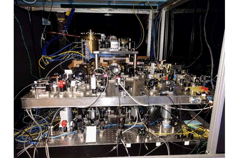
This January 25, 2017, image courtesy of Dr. Ed Marti, shows a strontium optical lattice clock, stored at Jun Ye's lab in the University of Colorado, Boulder.
Atomic clocks generate the approximate frequency that causes atoms of the element Cesium to jump to that higher energy state. Then, a detector counts the number of those energized atoms, adjusting the frequency if necessary to make the clock more precise.
So precise that since 1967, one second has been defined as 9,192,631,770 oscillations of a Cesium atom.
The Clock Inside GPS
The GPS receiver in your car or cellphone works by listening to satellites broadcast their time and location. Once the receiver has "acquired" four satellites, it can calculate its own position by comparing the signals. Since the signals are broadcast using microwaves that travel at the speed of light, an error of a millionth of a second on a GPS satellite clock could put you a quarter-mile off course.
Luckily, the atomic clocks on GPS satellites, due to their incredible stability and regular synchronization, maintain an error of less than 1 billionth of a second.
Though we can not make an atomic clock inside our house we can use one indirectly through a GPS receiver.
Two ways to make a clock
There are two ways this clock can be built. One way is with a GPS receiver which allows the clock to set its time automatically. There are a few dozen GPS satellites in orbit above the entire globe and all of them have extremely accurate clocks that make determining your position on earth possible. By tapping into the time broadcast from these satellites you can easily build a very precise clock.
The second way to build this project is with a battery-backed real-time clock module. This won't set itself like a GPS clock even not so accurate as GPS, but it will keep a good time for many years. Both options work great for making a clock!
So, Let's make an atomic clock!!!
In this post, I will show you how to make a super accurate digital clock using a GPS receiver and P10 LED Display module.
Supplies


1. Reyax RYS8830 GPS/GNSS Receiver Module: The RYS8830 module from Reyax is based on Sony CXD5605GF/CXD5605AGF technology & comes as a small SMD component. The RYS8830 GNSS modules can be used in tracking devices that need to be small and power-saving. The Reyax RYS8830 has a small form factor and ultra-low power consumption. The GPS/GNSS Module can be interfaced with any microcontroller & can be operated using a simple coin-cell battery.
The RYS8830 Module is a very small SMD Module and requires a PCB. So, in this tutorial, we will use an evaluation board (RYS8830 EVB). The RYS8830 Evaluation Board has an embedded power circuit along with the CP2102 Chip & a micro-USB port. So the board can be directly connected to the computer and using the GNNS Software you can start learning and exploring the feature of the RYS8830 Chip.
You can get details from: http://reyax.com.cn/products/rys8830/
2. Arduino UNO (nothing new to say about it): You can buy one from the aliexpress link (https://s.click.aliexpress.com/e/_Ake0bh)
3. 5V DC Power Supply (wall adapter); 2A will be good : You can buy one from aliexpress.com (https://s.click.aliexpress.com/e/_AtALRz)
4. P10 LED Display (preferably RED): You can buy one from aliexpress using this link (https://s.click.aliexpress.com/e/_AnnZLd)
Connections


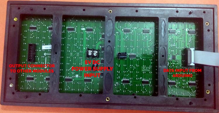
A P10 LED Display Module is the most suitable for designing any size of outdoor or indoor LED display advertisement board. This panel has a total of 512 high brightness LEDs mounted on a plastic housing designed for best display results. Any number of such panels can be combined in any row and column structure to design an attractive LED signboard.
The 32*16 module size means that there are 32 LEDs in each row and 16 LEDs in each column. So there is a total of 512 numbers of LEDs present in each module unit.
Features of a P10 LED Matrix Module:
- Brightness: 3500-4500nits
- Max Power Consumption: 20W
- Voltage Input: DC 5V
- IP65 Waterproof
- 1W Pixel Configuration
- High Viewing Angle
- High Contrast Ratio
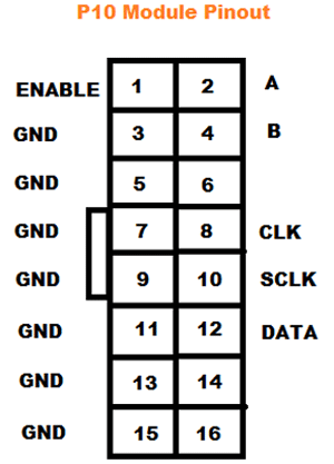
Pin description of P10 display module:
- Enable: This pin is used to control the brightness of the LED panel, by giving a PWM pulse to it.
- A, B: These are called multiplex select pins. They take digital input to select any multiplex rows.
- Shift clock (CLK), Store clock (SCLK) and Data: These are the normal shift register control pins. Here a shift register 74HC595 is used.
Connection with Arduino


Connection of GPS module & Arduino
...............................

Receiving & Understanding GPS Data


The REYAX RYS8830 is built on the high performance of the SONY CXD5605GF CXD5605AGF GNSS engine. The RYS8830 modules utilize concurrent reception of GNSS systems offering high sensitivity in a small SMD form factor.
It occupies a small SMD size of 121 mm2, which currently is the smallest GNSS module worldwide with an antenna. The operating voltage is around 1.65~1.95V. The frequency is 1561.098 MHz for BeiDou, 1575.42 MHz for GPS & 1602.5625 MHz for Glonass. RYS8830 has a built-in enhanced GNSS filter, a low noise amplifier, an embedded antenna, and it offers an option of an external antenna. the tracking sensitivity is around -161 dBm
Specifications
1. GNSS Center Frequency: 1561.098 MHz (BeiDou), 1575.42 MHz (GPS), 1602.5625 MHz (Glonass)
2. Navigation update rate: 1 Hz
3. Accuracy: up to 1m
4. Operating Temperature: -40°C to +85°C
5. Dimensions: 11mm*11mm*2.2mm
6. Power Supply Voltage: 1.8V
7. Satellite acquisition Current: 19 mA
8. Satellite tracking Current: 13 mA (GNSS continuous mode)
9. Satellite tracking Current: 2.6 mA to 8.2 mA (GNSS low power mode)
10. Idle Current: 3 mA (GNSS continuous mode)
Getting Time & Position Data
For getting the data we need to connect the RYS8830 EVB evaluation board with the PC. So use a Micro-USB Data cable to connect RYS8830 EVB to the computer. Once connected a red light will flash up indicating the evaluation board is correctly powered. Run any serial monitor software (e.g. Arduino serial monitor, PuTTY) and choose the COM port for the evaluation board. Send @GCD from the serial monitor to the EVB to cold start the device. You will get the data like the following image:

The data shown in the figure above means that the connection is established successfully, but it is unable to perform positioning.
In this case, please place the EVB on the balcony or near the window, or outdoors for testing, because GPS is less stable in searching signals indoors.
After waiting for a while, if the serial monitor lists similar data in its window as the figure shows below, it means GPS has performed positioning.
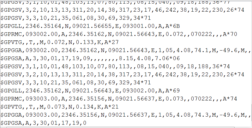
For its first positioning after cold starts, the GPS module normally takes 1-3 minutes to finish this positioning successfully in the open air with good weather. So, please be patient. Moreover, if there is bad weather, it may take more time for positioning, or even unable to perform positioning sometimes.
The data you are getting over the serial interface is actually NMEA sentences.
NMEA is an acronym for the National Marine Electronics Association. This is a standard message format for Nearly all GPS receivers.
The NMEA standard is formatted in lines of data called sentences. Each sentence is comma-separated to make it easier to parse by computers and microcontrollers.
These NMEA sentences are sent out at an interval called the update rate which is 1 sec for the RYS8830.
Parsing NMEA Sentences
There are many sentences in the NMEA standard, the most common ones are:
- $GPRMC (Global Positioning Recommended Minimum Coordinates) provides the time, date, latitude, longitude, altitude and estimated velocity.
- $GPGGA sentence provides essential fix data which provide 3D location and accuracy data.

Let’s take an example of $GPRMC NMEA sentence from a GPS receiver.
$GPRMC, 123519, A, 4807.038, N, 01131.000, E,022.4, 084.4, 230394, 003.1, W*6A
$ --> Every NMEA sentence starts with $ character.
GPRMC --> Global Positioning Recommended Minimum Coordinates
123519 -->Current time in UTC – 12:35:19
A --> Status A=active or V=Void.
4807.038,N --> Latitude 48 deg 07.038′ N
01131.000,E --> Longitude 11 deg 31.000′ E
022.4 -->Speed over the ground in knots
084.4 --> Track angle in degrees True
220318 --> Current Date – 22 rd of March 2018
003.1,W --> Magnetic Variation
*6A --> The checksum data, always begins with *
For more details about the NEMA please refer to the software guide attached here.
Downloads
Programming


Test code for extracting time from the NEMA data received by the GPS module.
char inChar;
String gpsData;
String sGPRMC;
String utc_time;


void setup() {
   Serial.begin(9600);
}


void loop() {

  while (Serial.available()) {
    inChar = Serial.read();
    gpsData += inChar;
    if (inChar == '$') {
      gpsData = Serial.readStringUntil('\n');
      break;
    }
  }
  //gpsData = "$GPRMC,013856.000,A,000.9090,N,9090.90,E,0.0,038.1,310814,,,A*62";
  Serial.println(gpsData);
  sGPRMC = gpsData.substring(0, 5);


  if (sGPRMC == "GPRMC") {
    Serial.flush();
    utc_time = gpsData.substring(6, 12);

    float utc_time_f = utc_time.toFloat();
    int hour = int(utc_time_f)/10000;
    int temp_min = int(utc_time_f)/100;
    int minute = temp_min%100;
    int second = int(utc_time_f)%100;

    Serial.print(hour);
    Serial.print(":");
    Serial.print(minute);
    Serial.print(":");
    Serial.println(second);

  }
}
The Clock Code
First of all, include all the dependent libraries in the program. Here we are using “DMD.h” Library for P10 led operations, download this library from here and install it in Arduino IDE. After that include the library for “TimerOne.h” which will be used for interrupt tasks. This library can be downloaded from here.
Then, include all the required fonts library, in our case we are using “Arial Black font” for the display.
/*
 * PIN Configuration
 * Arduino              P-10
 * -D6          ->      -A
 * -D7          ->      -B
 * -D8          ->      -SCLK
 * -D9          ->      -OE
 * -D11         ->      -DATA
 * -D13         ->      -CLK
 * -GND         ->      -GND
 *
 * Arduino              RYS8830 EVB
 * -TX          ->      -RX
 * -RX          ->      -TX
 * -GND         ->      -GND
 */


#include <DMD.h>
#include <TimerOne.h>
#include <SPI.h>
#include <SystemFont5x7.h>
#include <angka6x13.h>


DMD dmd(1, 1);


char inChar;
String gpsData;
String sGPRMC;
String utc_time;
int hour, minute, second, temp_min;

void ScanDMD()
{
  dmd.scanDisplayBySPI();
}


void setup()
{
  Serial.begin(115200);
  Serial.println("@GCD"); //cold start the gps
  pinMode(2, OUTPUT);//----pin 2 make alarm ---connect a buzzer


  Timer1.initialize( 500 );
  Timer1.attachInterrupt( ScanDMD );
  dmd.clearScreen( true );

}


void loop() {


  while (Serial.available()) {
    inChar = Serial.read();
    gpsData += inChar;
    if (inChar == '$') {
      gpsData = Serial.readStringUntil('\n');
      break;
    }
  }
  //sample gpsData = "$GPRMC,013856.000,A,000.9090,N,9090.90,E,0.0,038.1,310814,,,A*62";
  sGPRMC = gpsData.substring(0, 5);


  if (sGPRMC == "GPRMC") {
    Serial.flush();
    utc_time = gpsData.substring(6, 12);

    float utc_time_f = utc_time.toFloat();
    hour = int(utc_time_f)/10000;
    temp_min = int(utc_time_f)/100;
    minute = temp_min%100;
    second = int(utc_time_f)%100;

    //Serial.print(hour);
    //Serial.print(":");
    //Serial.print(minute);
    //Serial.print(":");
    //Serial.println(second);
  }


  display_time();

}


void display_time()
{
  long start = millis();
  dmd.clearScreen( true );
  while (millis() - start < 10000) {

    long start = millis();


    ///display time///
    dmd.selectFont(angka6x13);
    //int minute_e = 24;
    //int hour = 8;
    //if(hour>12){hour = hour - 12;}
    //if(hour==0){hour = 12;}

    String xjam = convert(hour) ; //show hour
    int pjg = xjam.length() + 1;
    char sjam[pjg];
    xjam.toCharArray(sjam, pjg);
    dmd.drawString(1, 0, sjam, pjg, 0);


    String xxjam = convert(minute) ; //show minute
    int xpjg = xxjam.length() + 1;
    char xsjam[xpjg];
    xxjam.toCharArray(xsjam, xpjg);
    dmd.drawString(18, 0, xsjam, xpjg, 0);


    ///blinking second


    dmd.selectFont(SystemFont5x7);
    dmd.drawChar( 14,  4, ':', GRAPHICS_NOR   );   // clock colon overlay on
    delay( 1000 );
    dmd.drawChar( 14, 4, ':', GRAPHICS_OR   );   // clock colon overlay off
    delay( 1000 );


  }
}


//----------------------------------------------------------------------
///convert single digit with a leading zero


String convert(int sInput) {
  if (sInput < 10)
  {
    return "0" + String(sInput);
  }
  else
  {
    return String(sInput);
  }
}