Superimposition Speaker Case
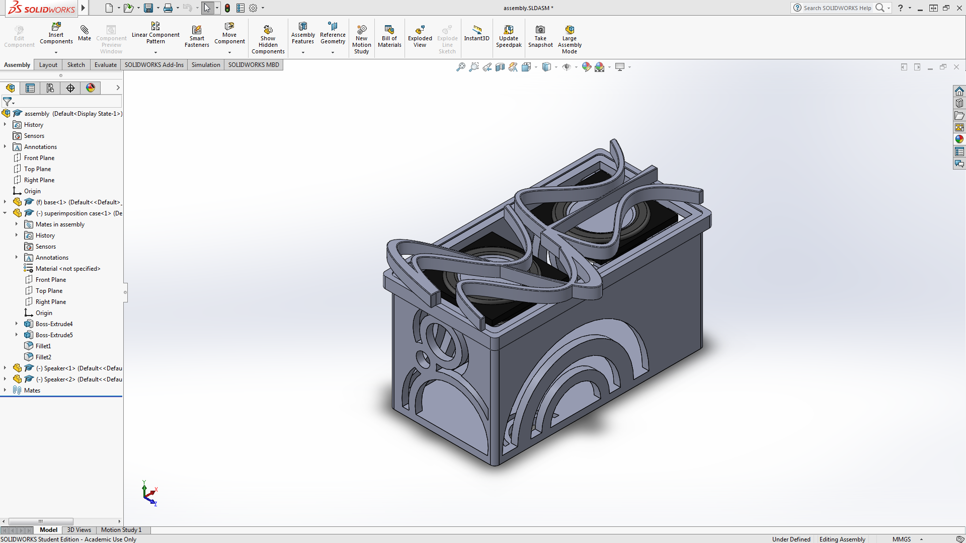
This design of a speaker case is based on the superimposition of sound waves. In other words, this speaker case visually illustrates how sound waves interact with each other. The top of the speaker case shows the constructive and deconstructive superimposition of two separate sound waves. One side shows how the two waves interact in a way that produces a bigger wave. The other side shows how the two waves interact and cancel each other out. This results in a flat line, in other words there is no sound.
This design is entirely designed through Solidworks and is fabricated with a 3D printer. This instructable will go through the 3D modelling process on Solidworks and the basic settings on cura to prepare the file for printing.
Creating the Base
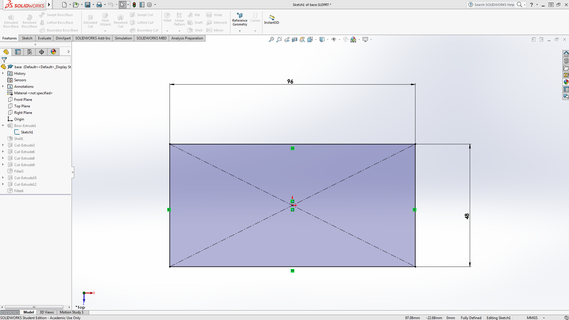
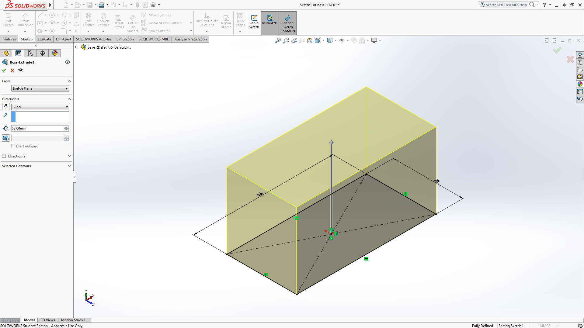
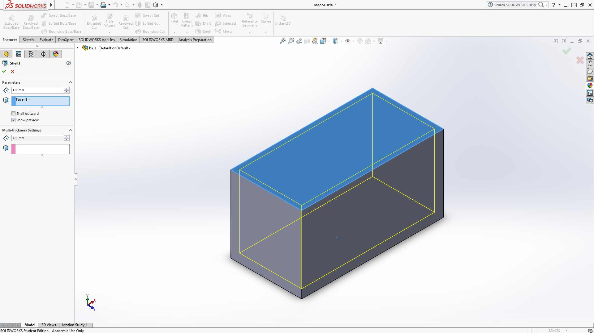
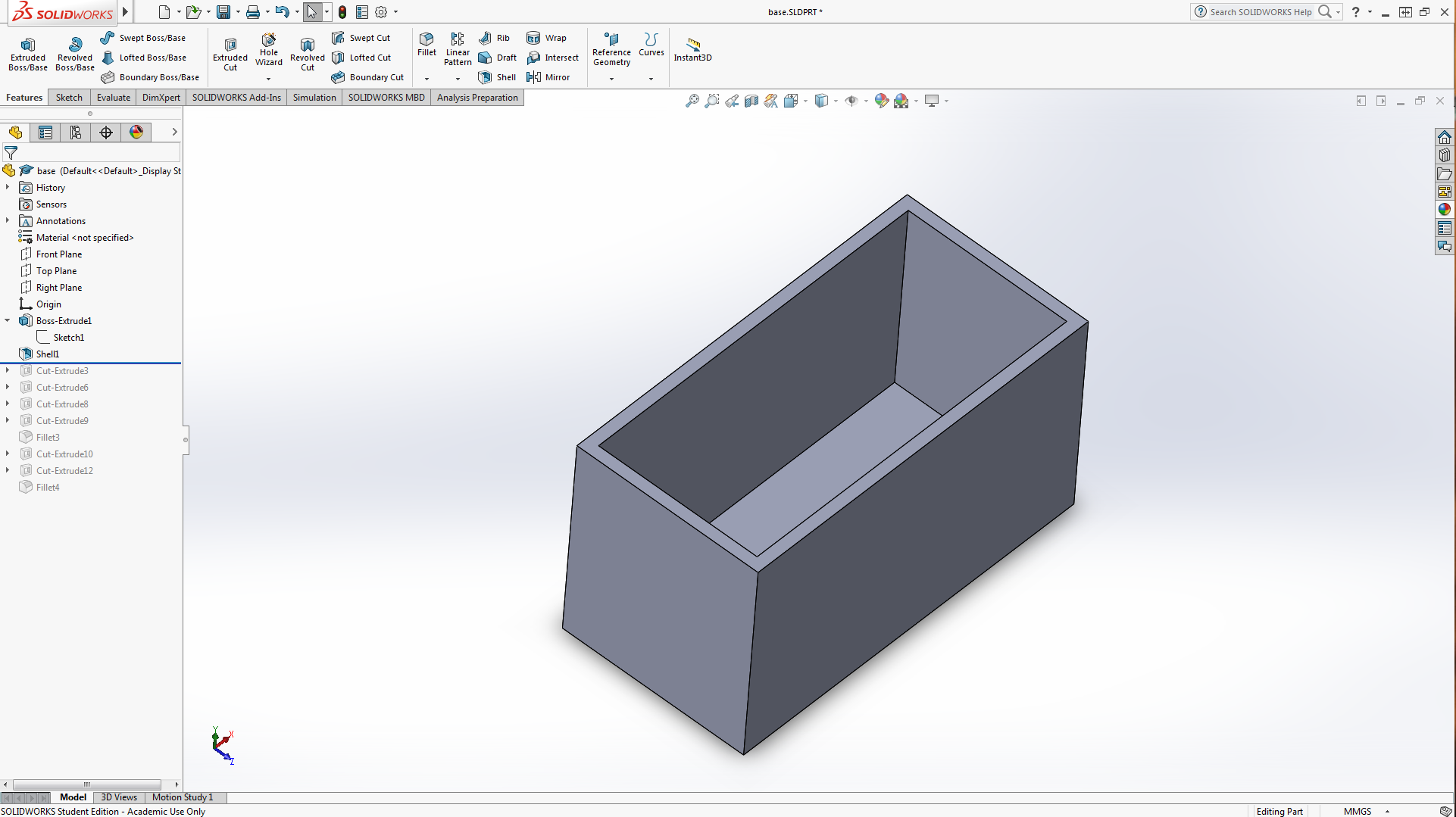
Start by sketching a 96mmx48mm Rectangle on the top plane. Then Boss extrude 52mm out. Finally select the top face and click on Shell with 3mm walls. It should end up looking like a rectangular box with an open top.
Creating Base Patterns
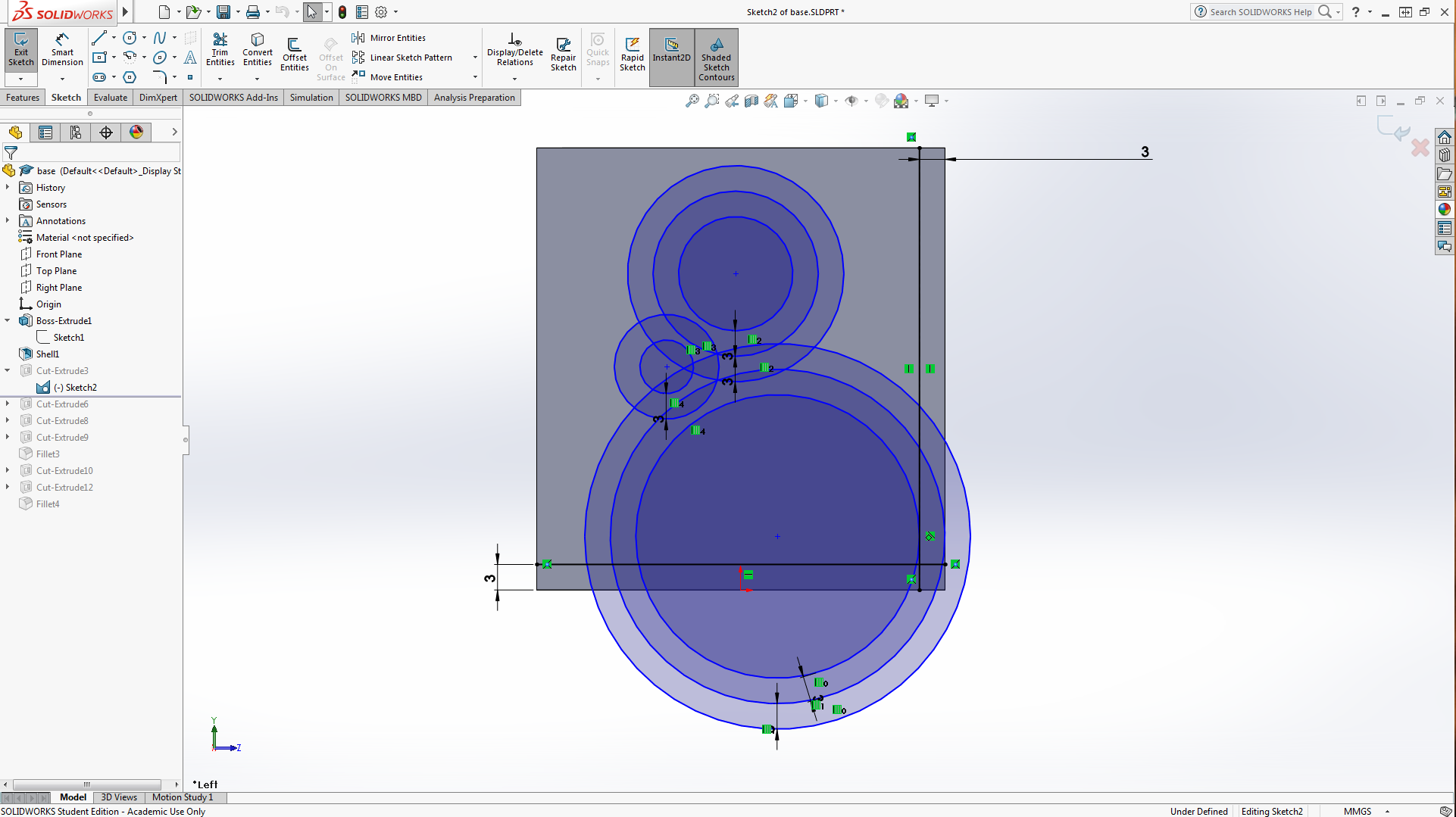
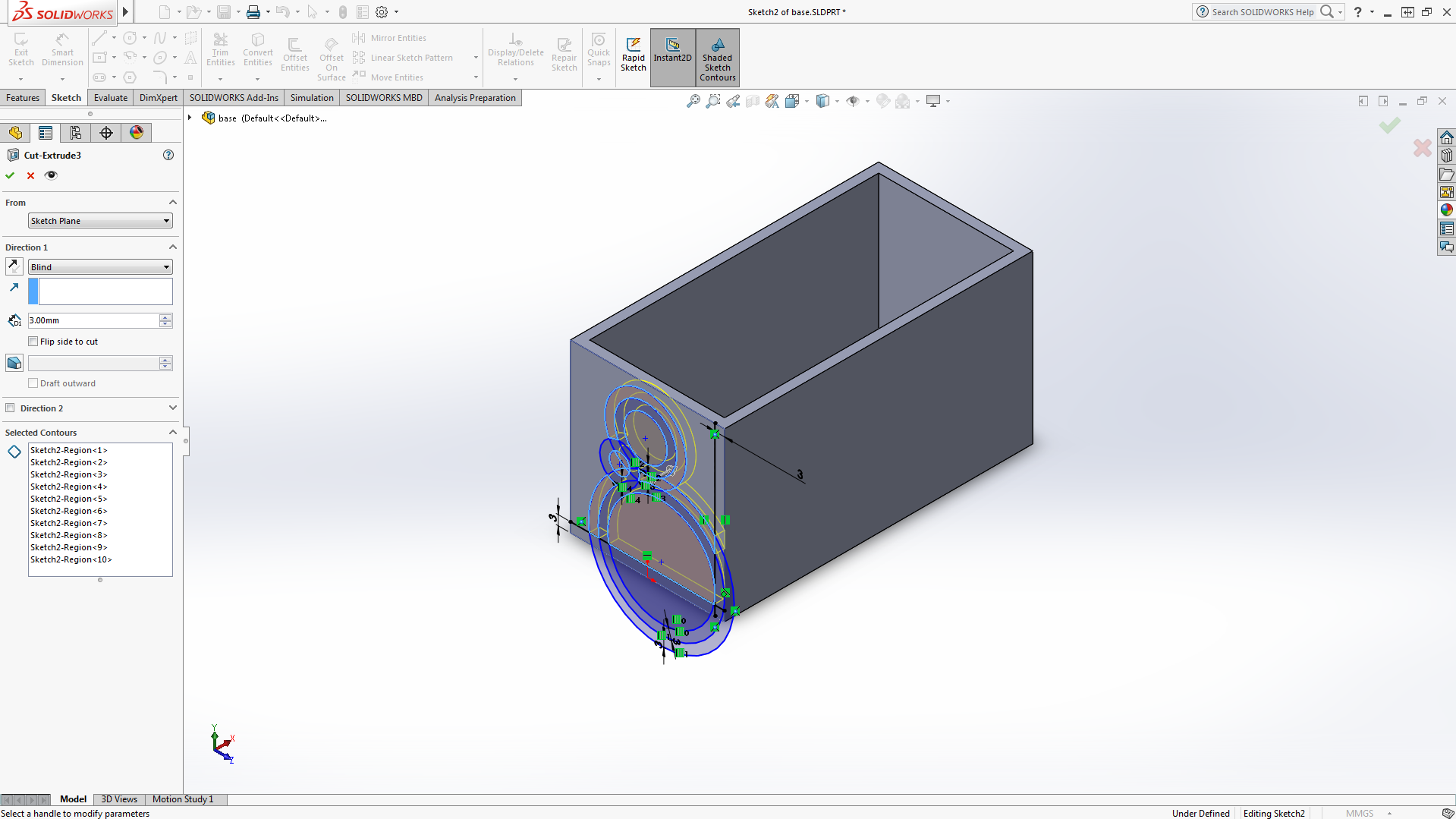
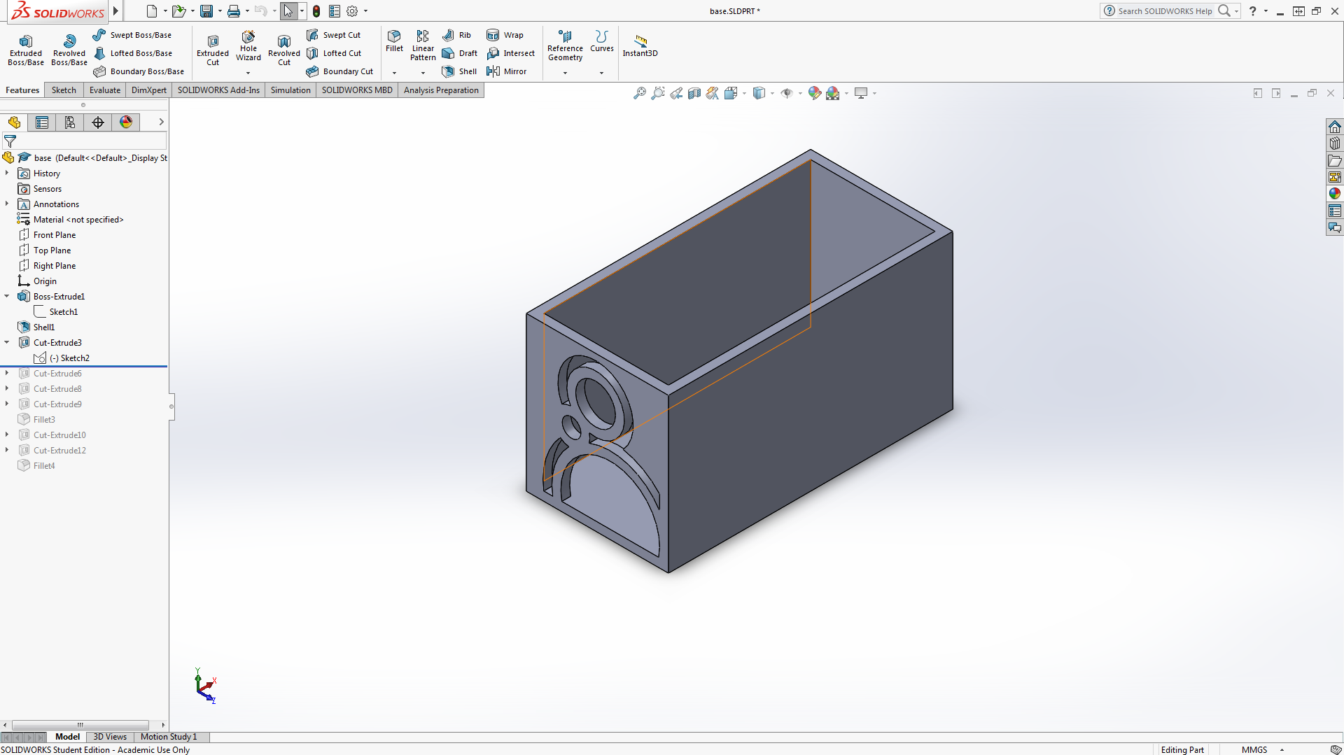
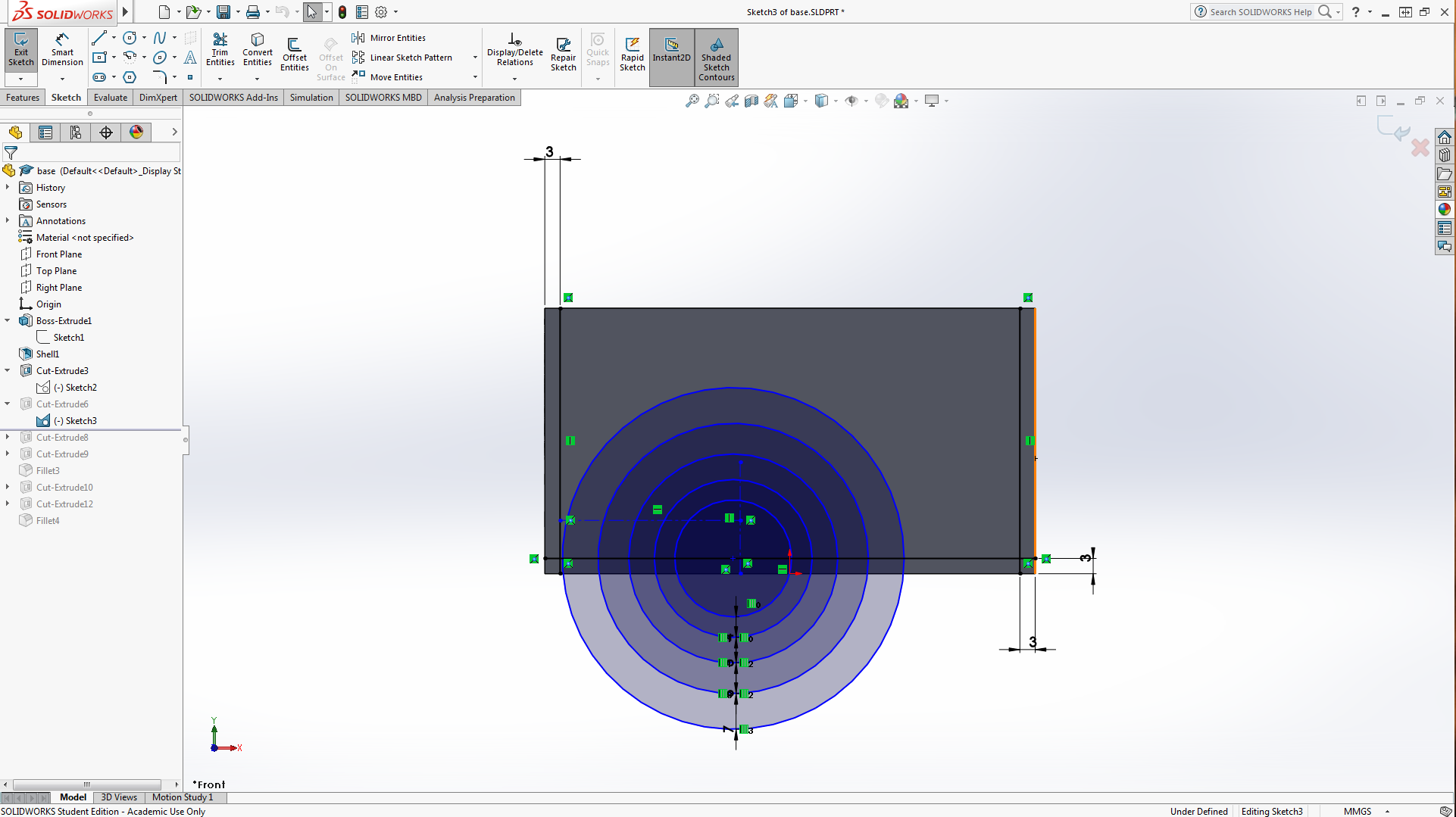
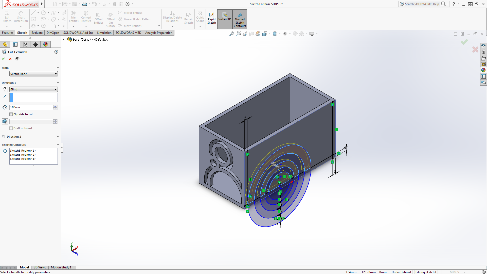
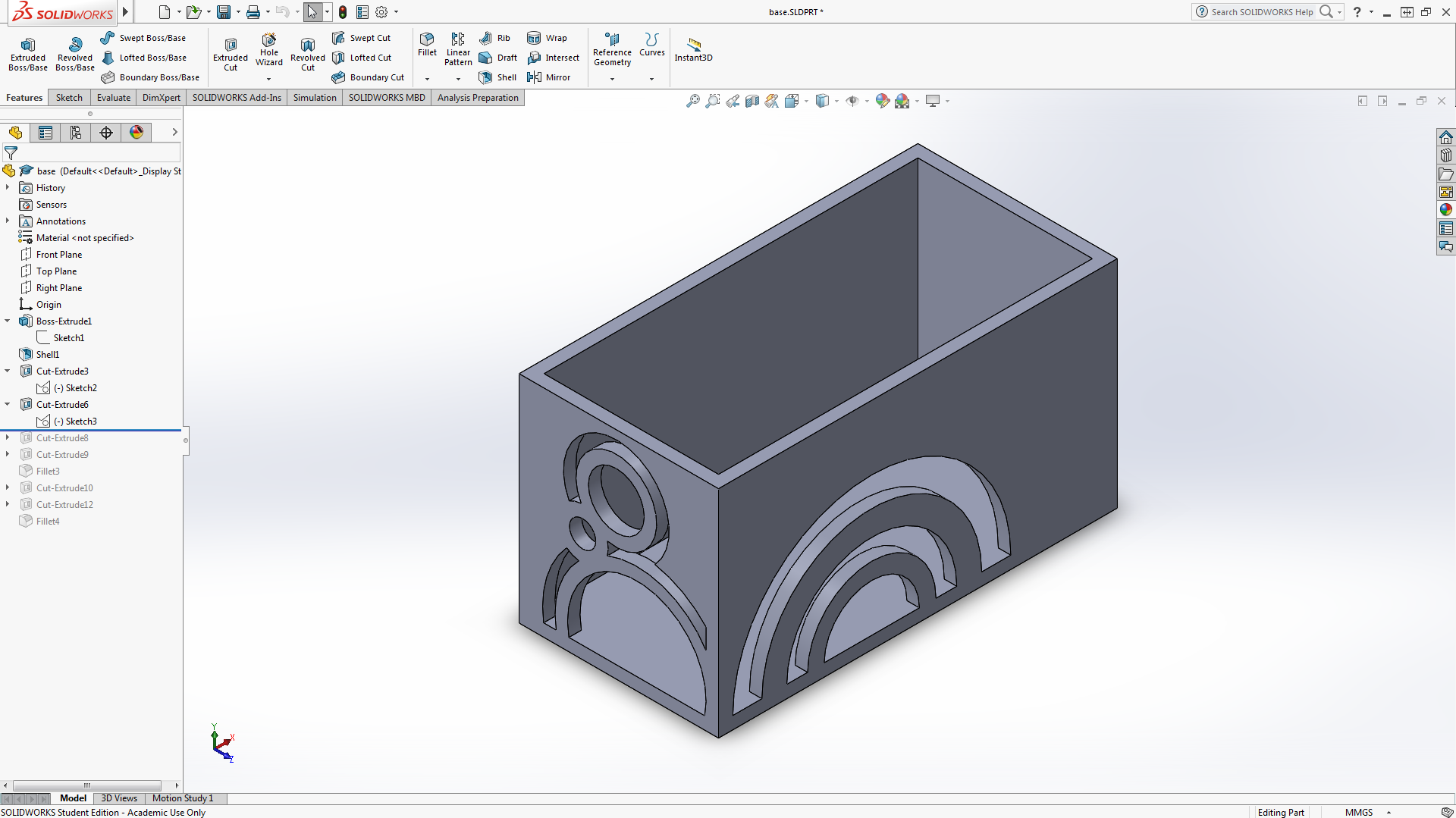
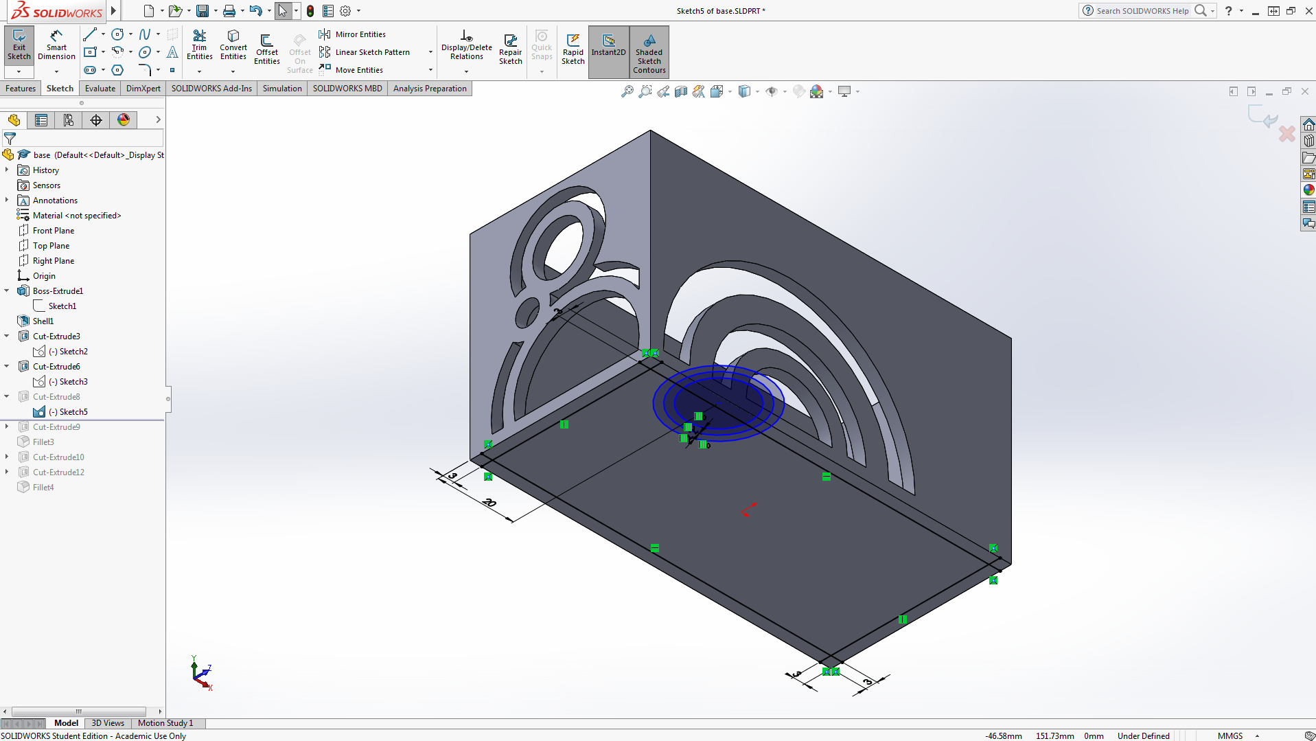
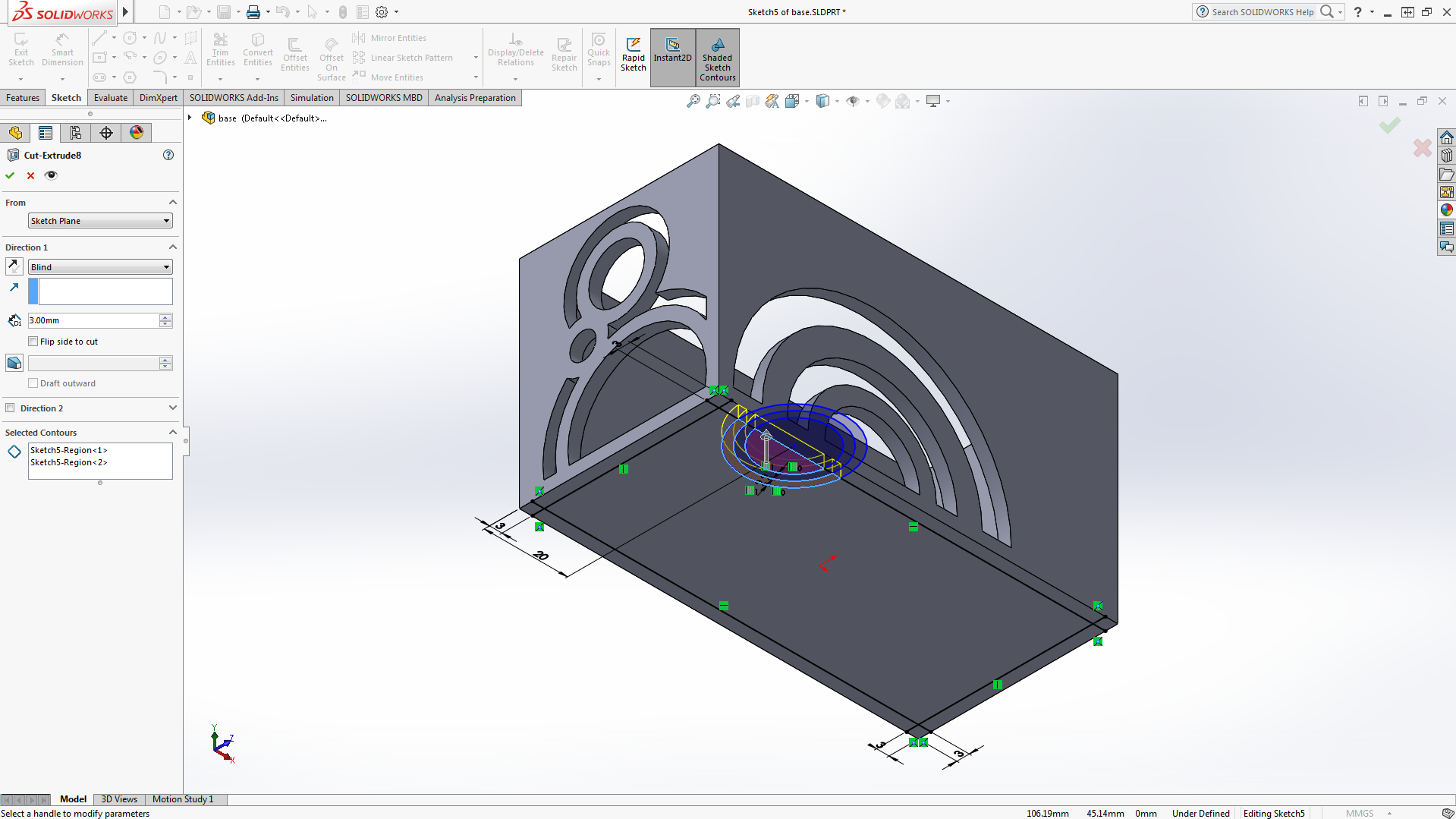
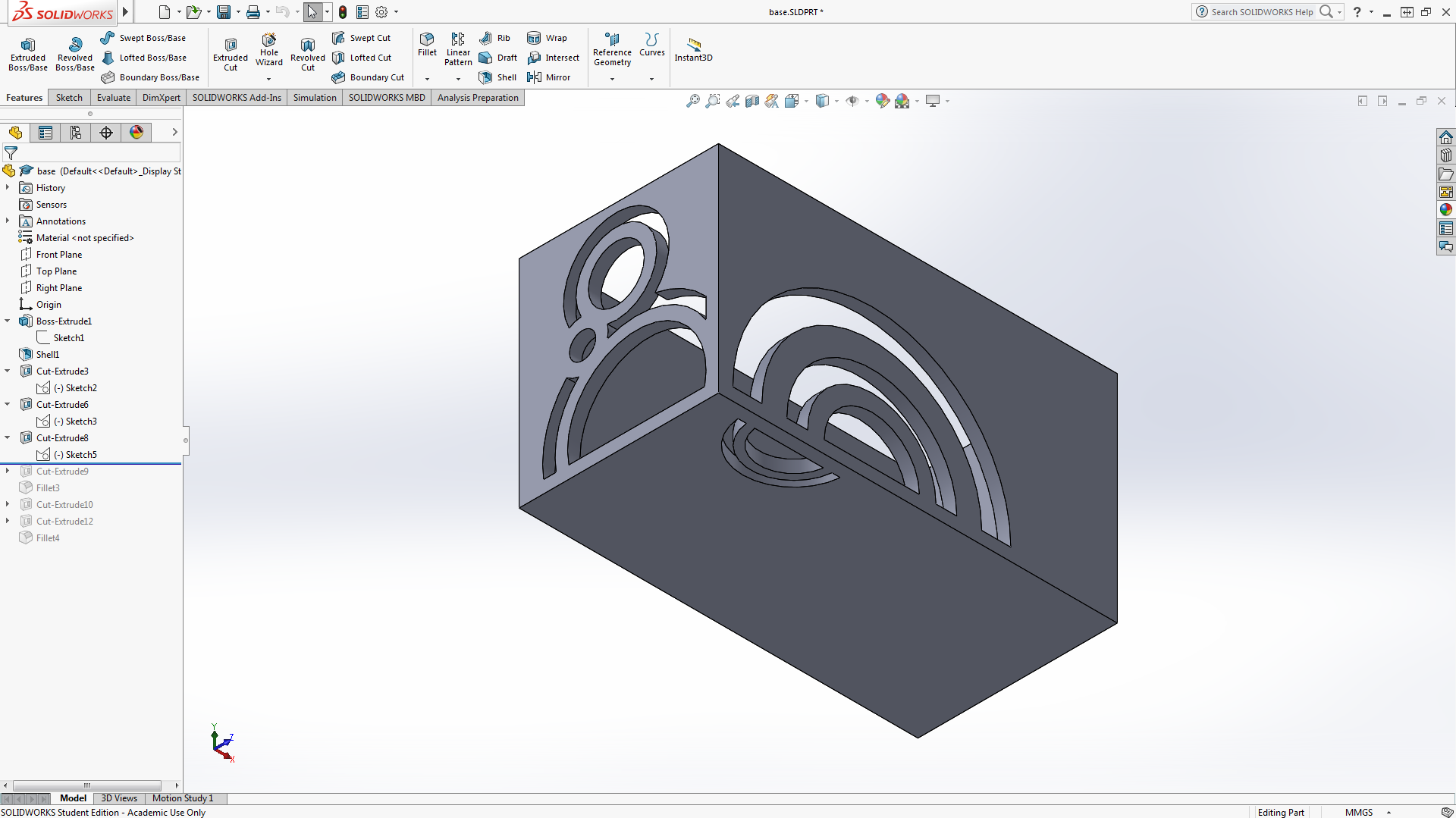
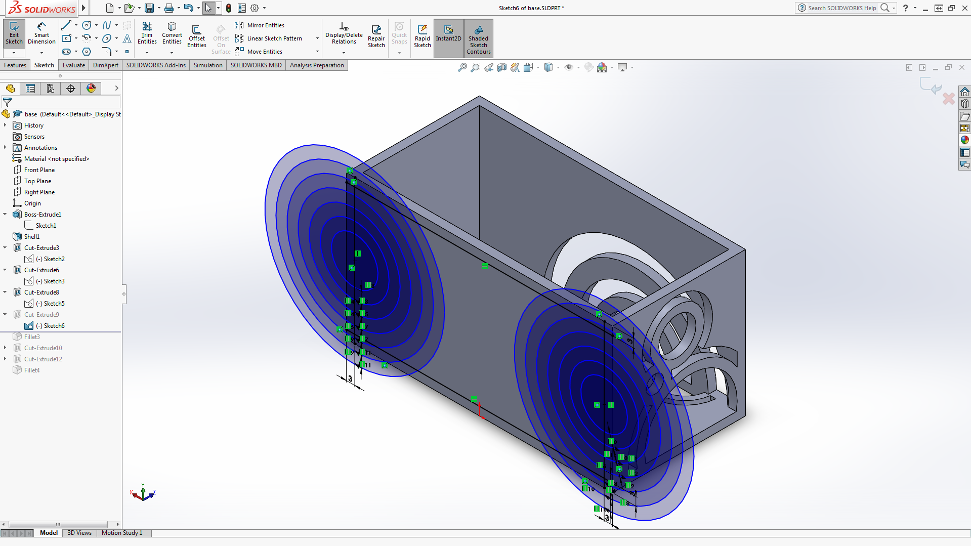
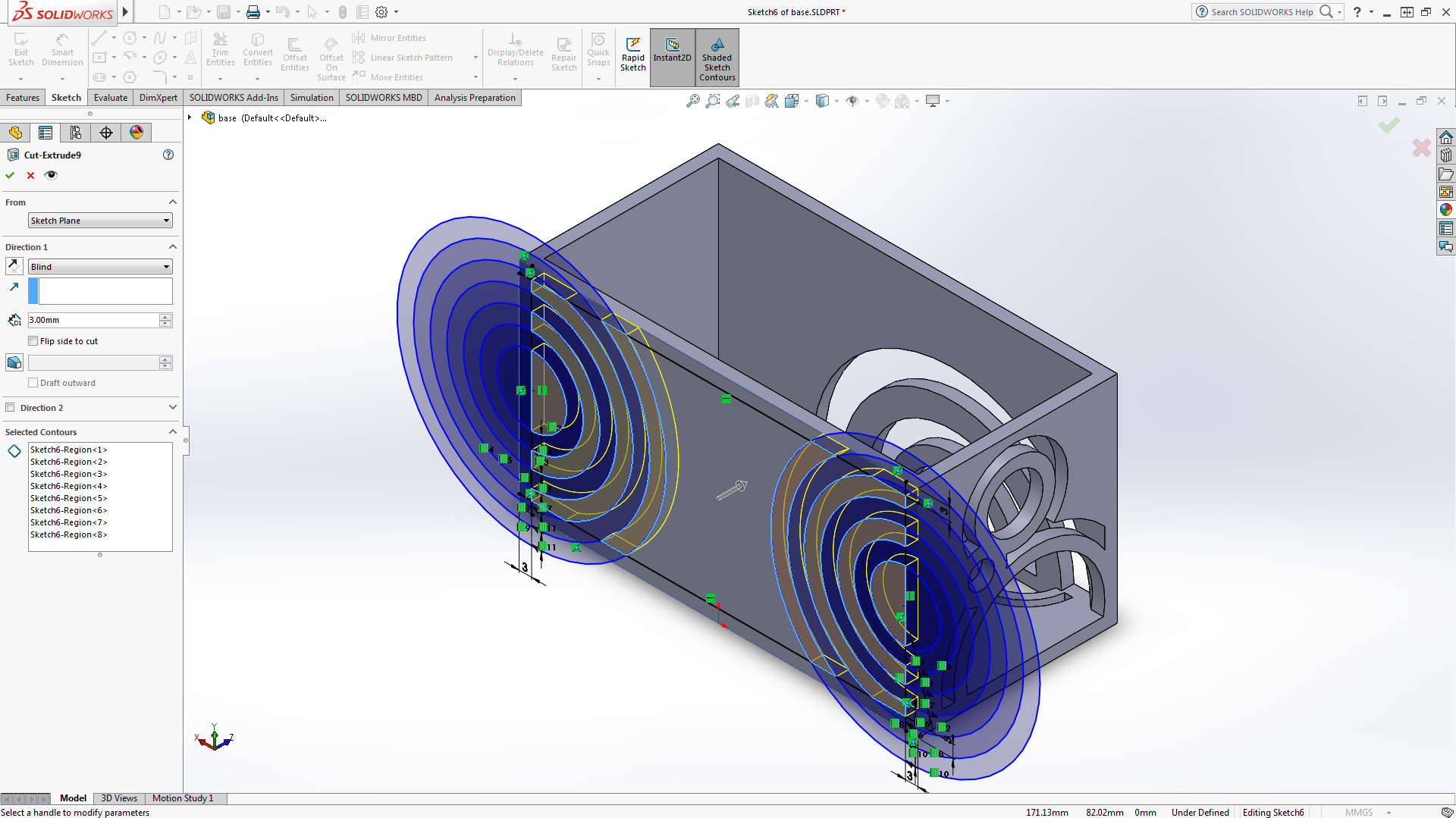
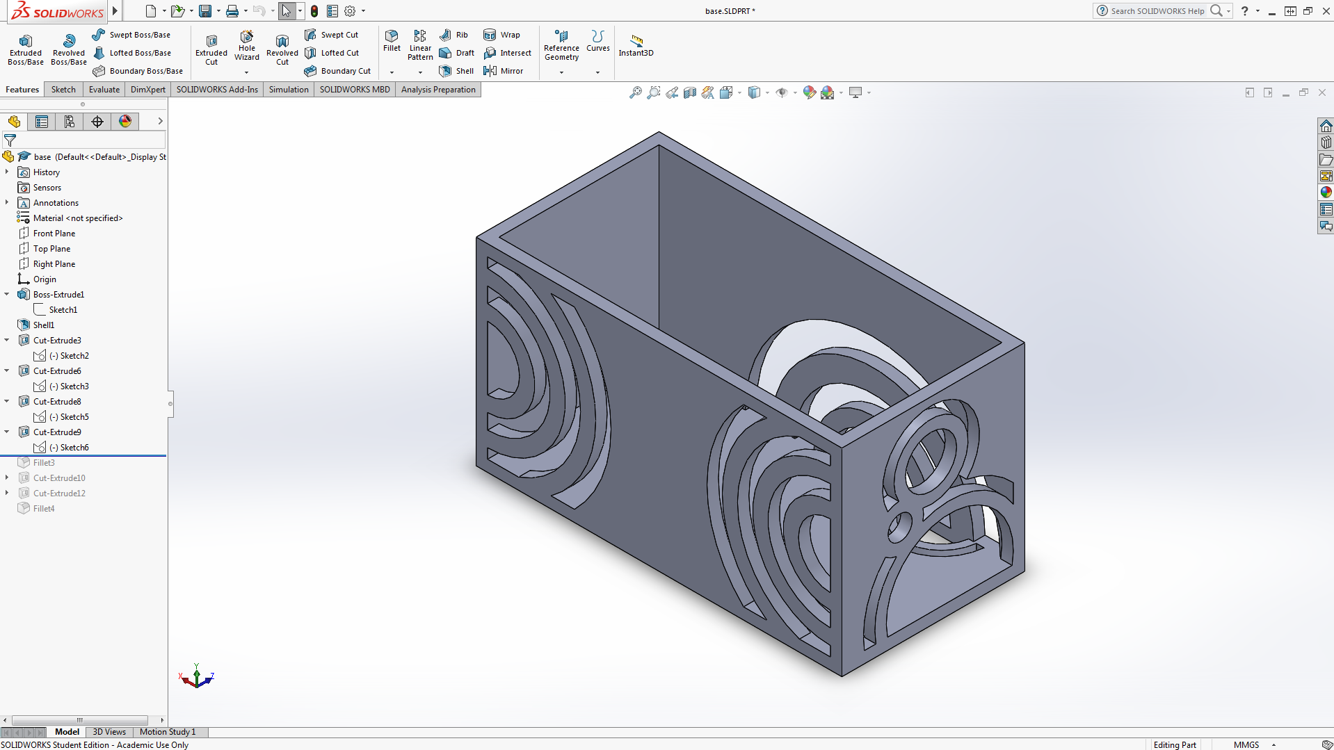
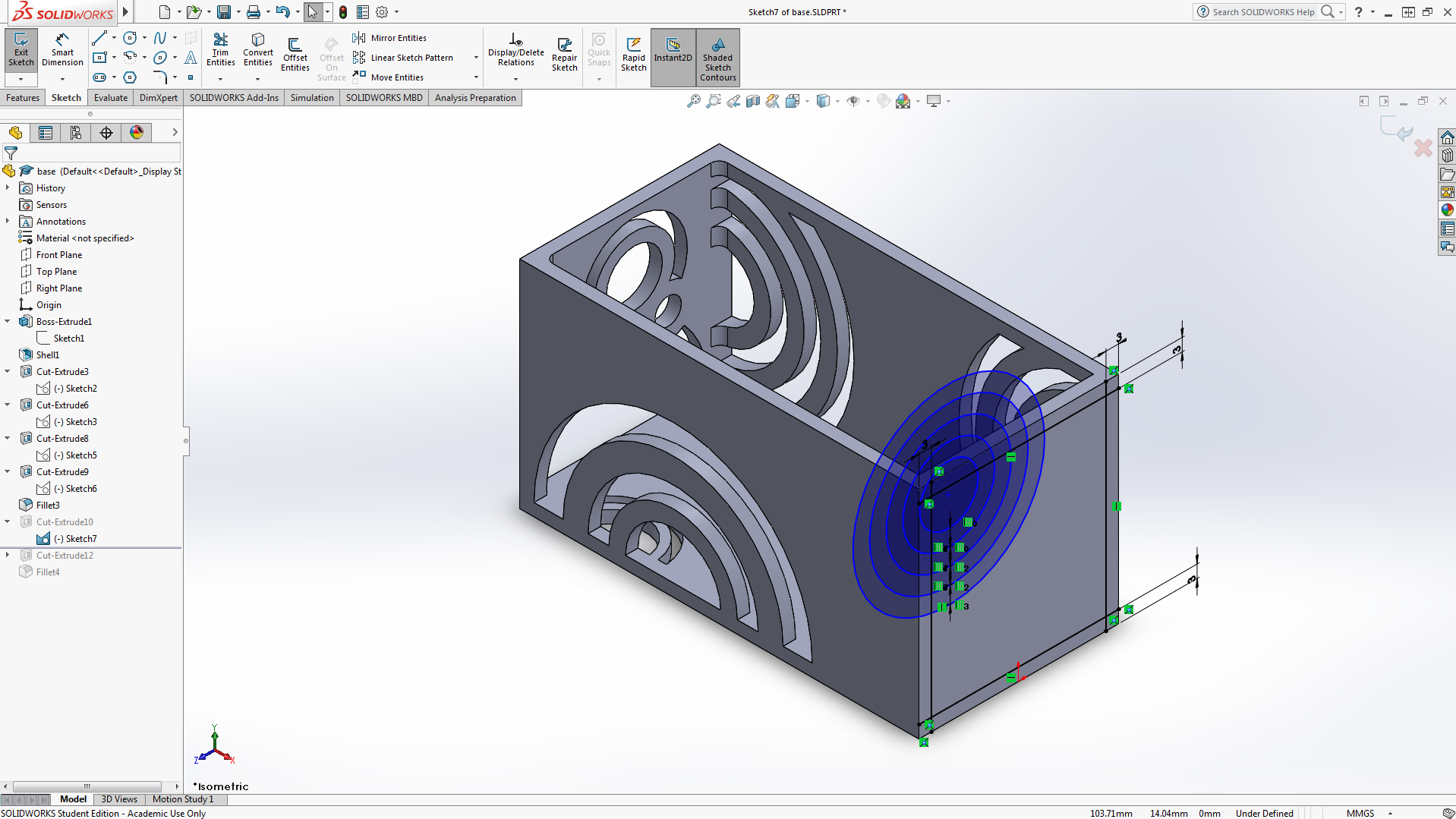
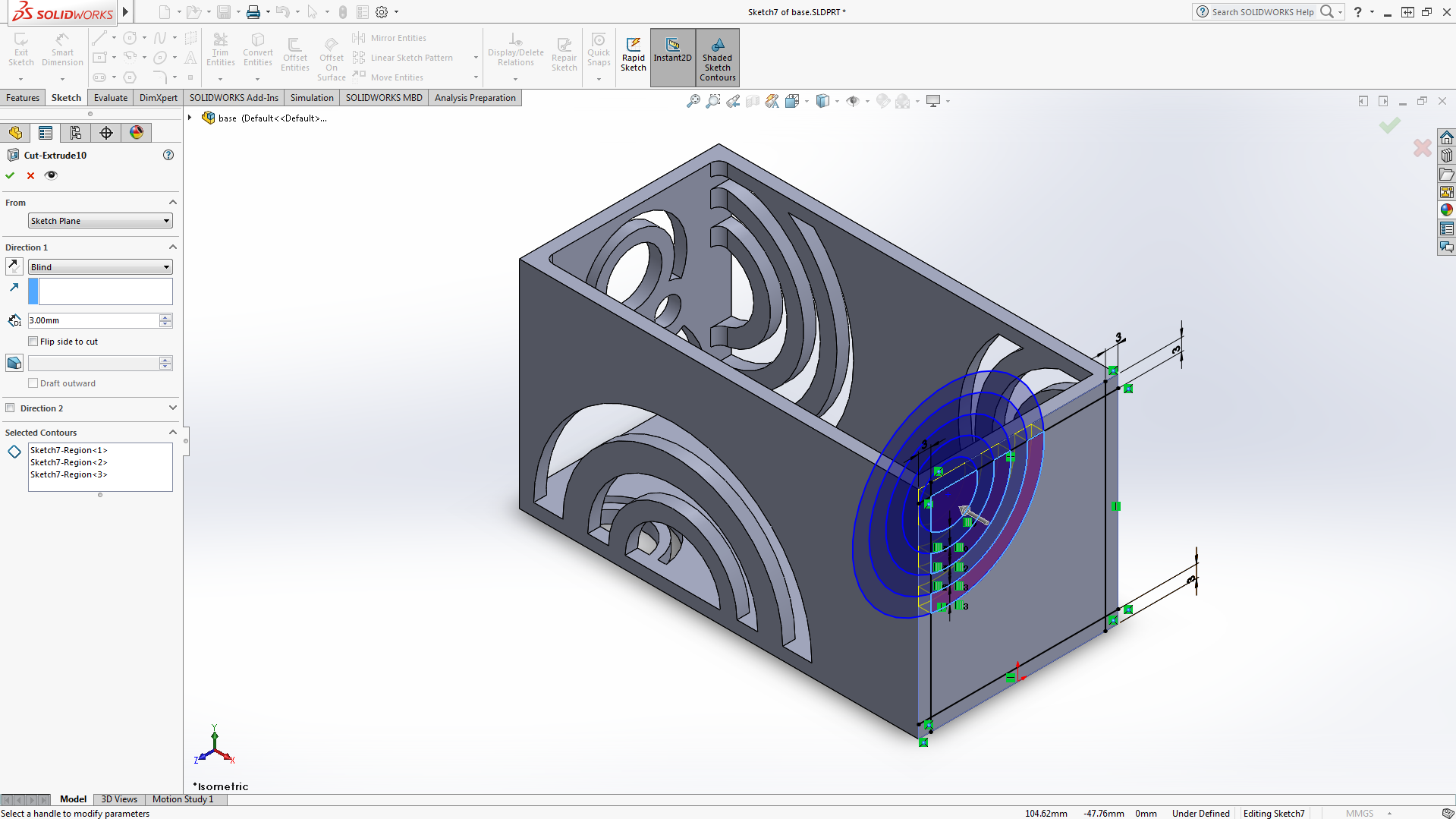
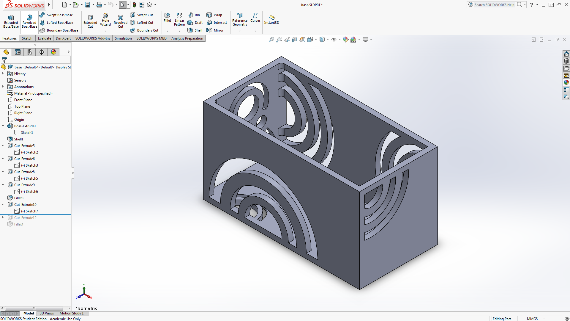
Start by selecting an outer face on the rectangular box. Then sketch a circle on the face. Select the circumference of the circle and select offset entities to form another line outside the original circle. Sketch multiple circles and repeat the previous steps until the circles overlap. Select the extended cut feature and click the middle circles and every second circle outside them. Ensure the extended cut is the same depth as the walls of the box. Repeat this for all sides of the box until you achieve your desired patterns.
Filleting the Edges
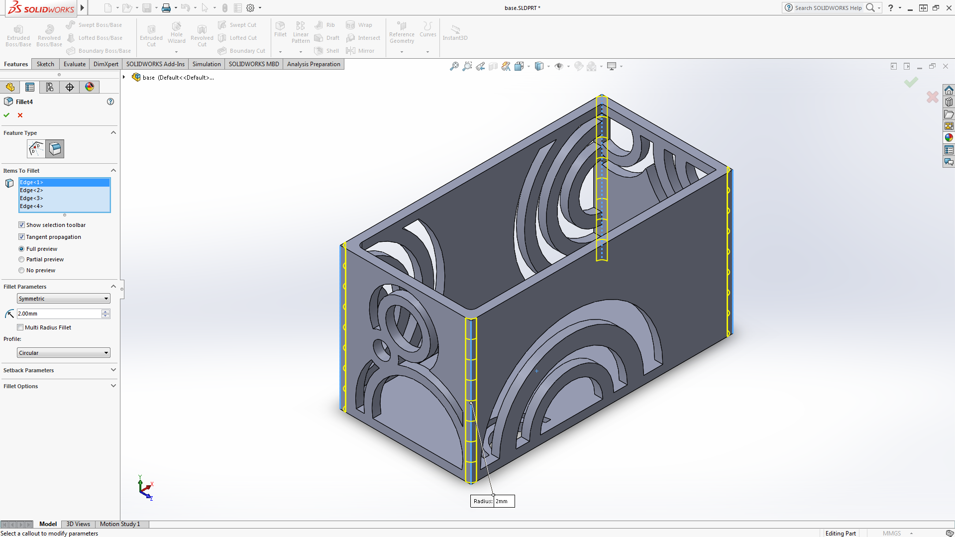
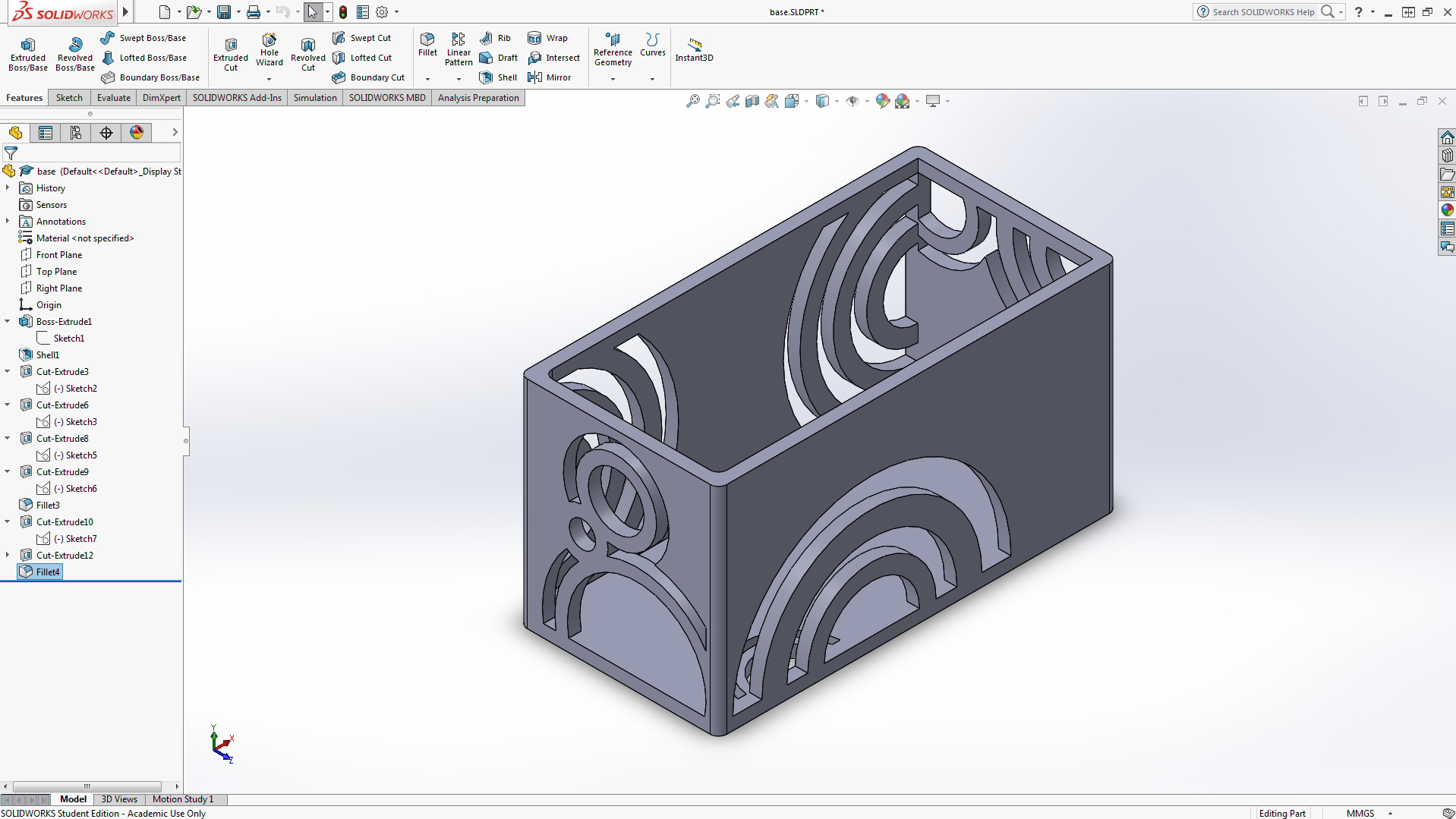
Select the corners of the box and select the fillet feature. Fillet the corners to your desired dimension. around 2mm is recommended.
Creating Pattern for Top of Case
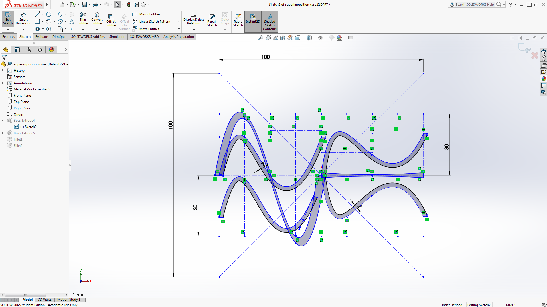
Start by laying out an area of 100mmx100mm to ensure it is within the 10x10x10 restriction.Then sketch numerous centre lines which will be used as guides. Draw centre lines 30mm above and below the middle and split the horizontal with 8 sections 12.5mm apart.
In the left half, draw two sound waves with identical orientations using spline. One above and one below the middle line. Then draw a bigger sound wave overlapping the initial two sound waves.
In the right half, draw two sound waves mirrored over the middle. Then draw a straight line between the two sound waves.
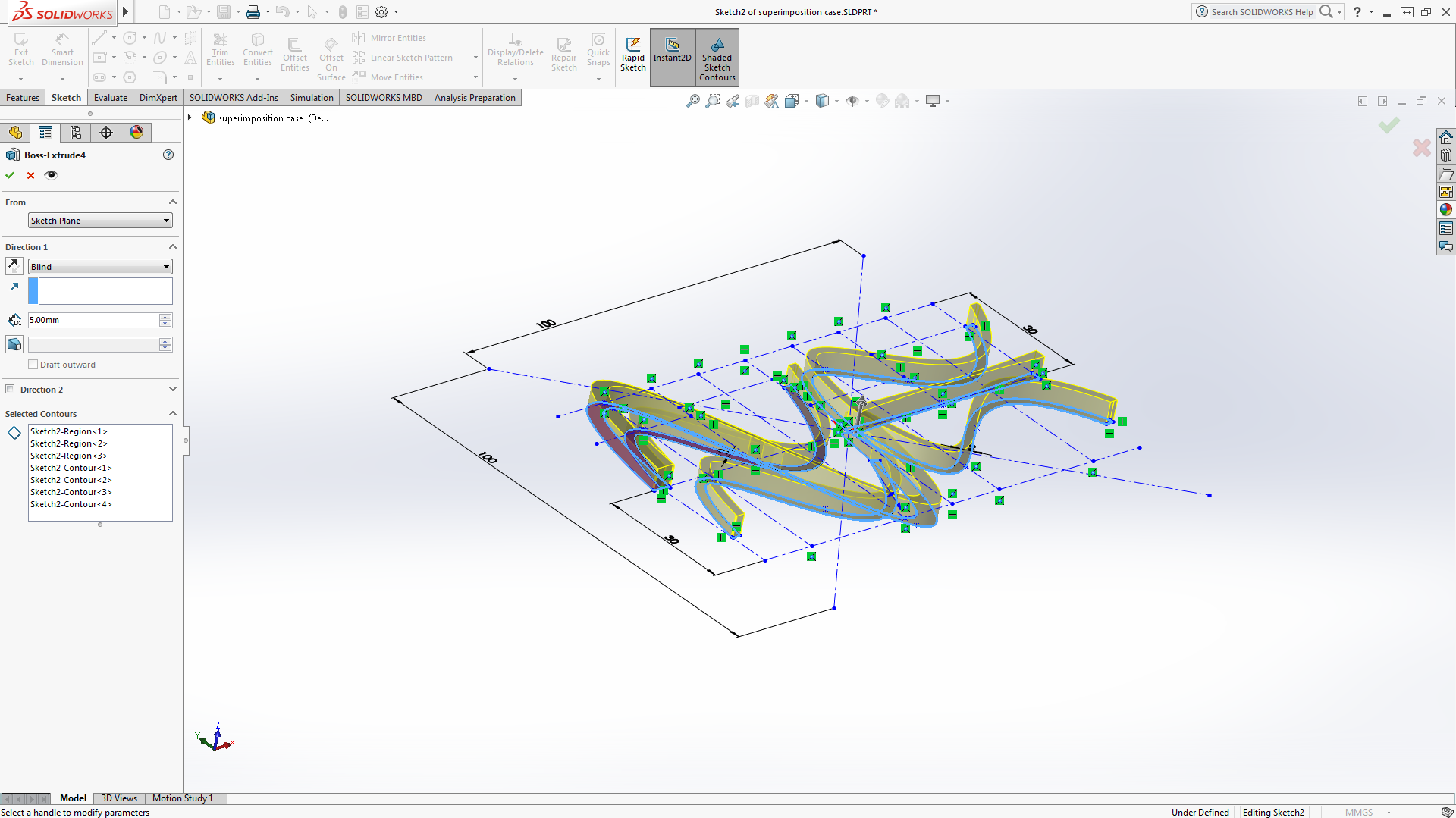
Finally, boss extrude everything 5mm out.
Lid Base
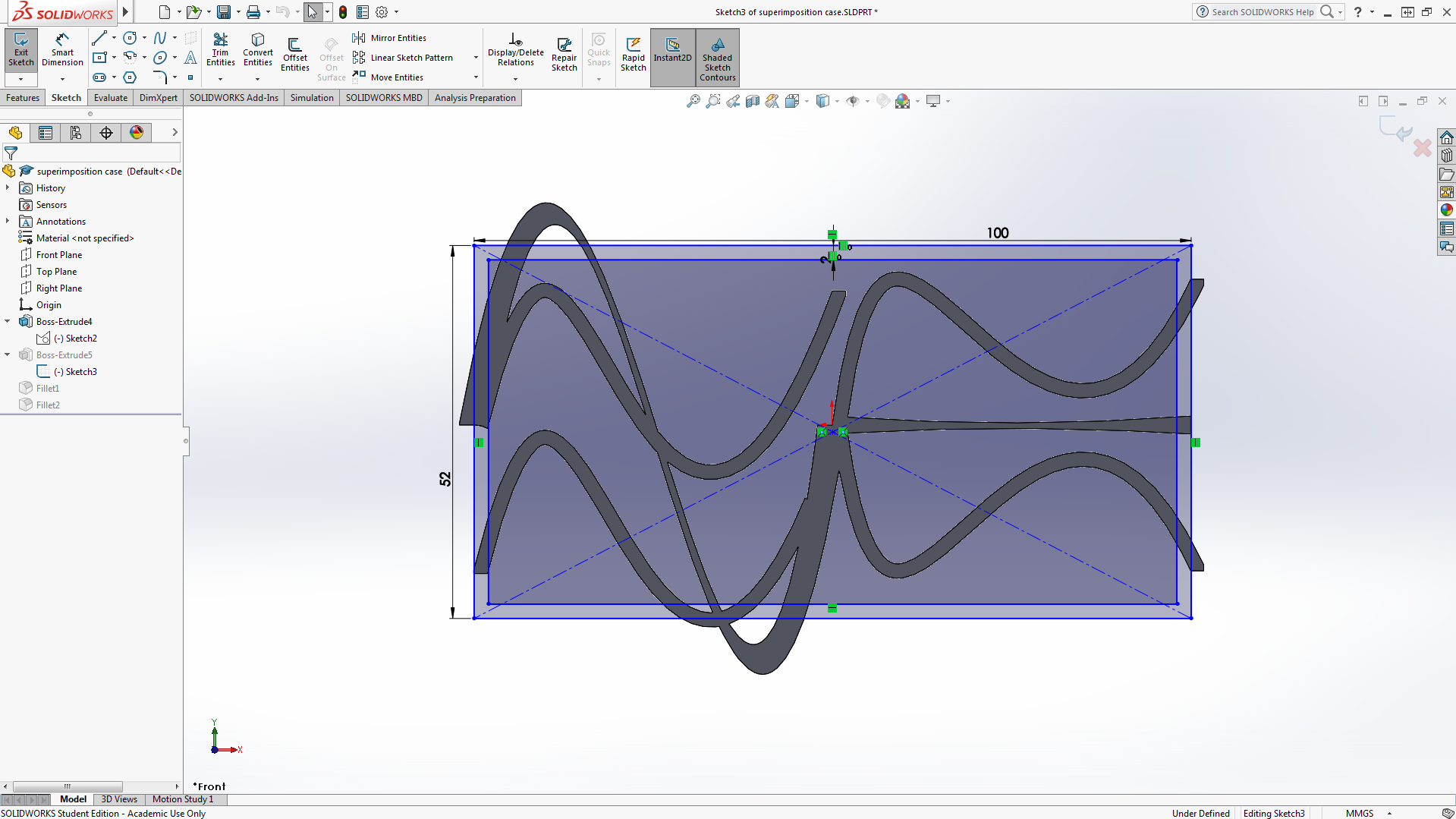
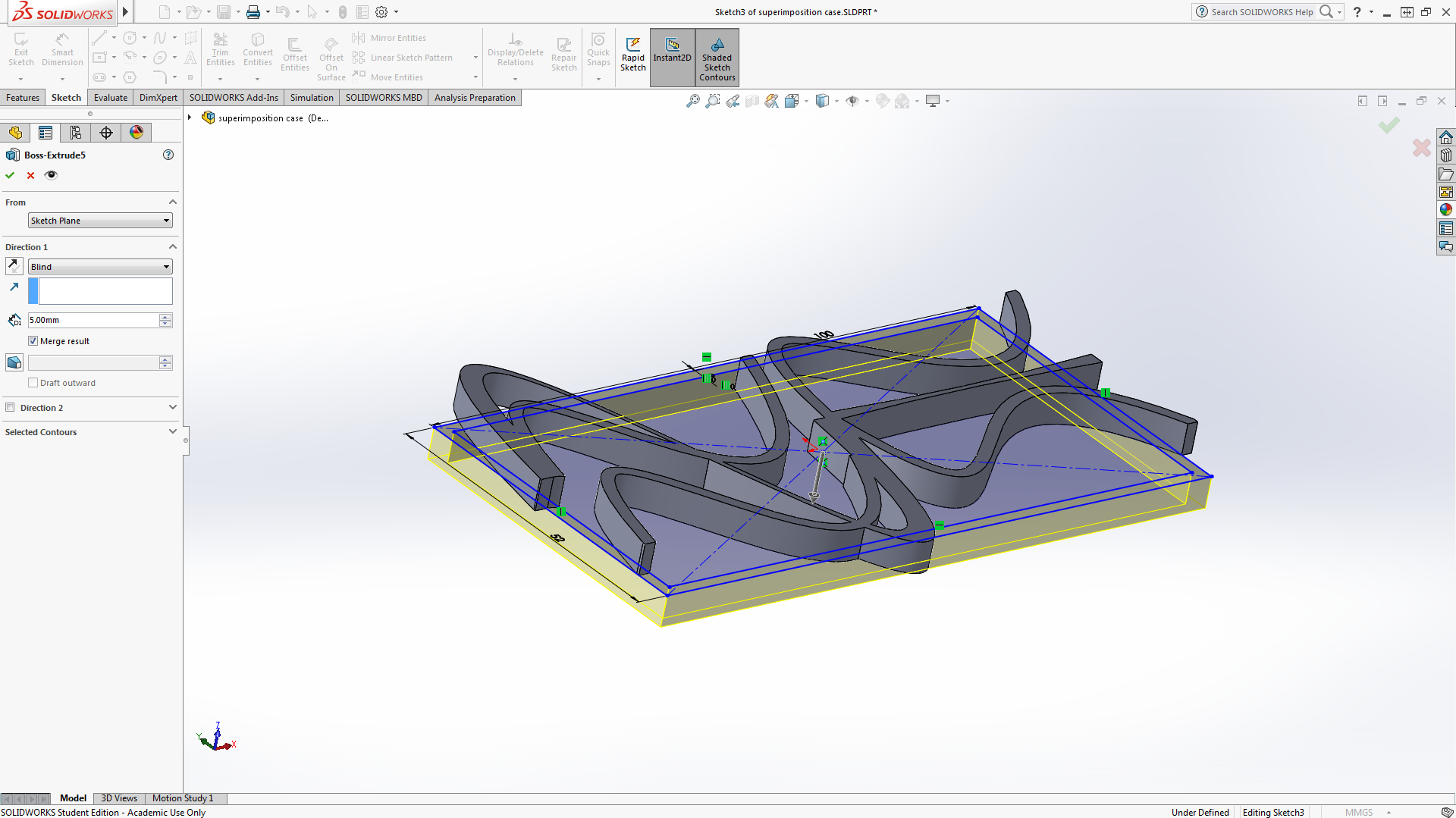
Start by sketching a rectangle with dimensions 100mmx52mm. Ensure this is sketched underneath the sound wave patterns.Then select the outer lines of the rectangle and select offset entities to form another rectangle 2mm inside the initial rectangle.
Finally boss extrude the area between the two rectangles 5mm out.
Filleting the Top
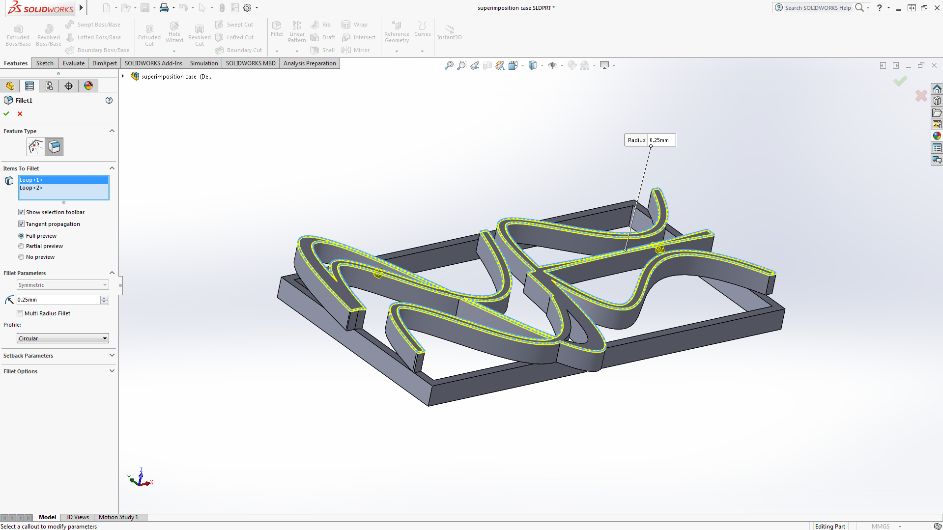
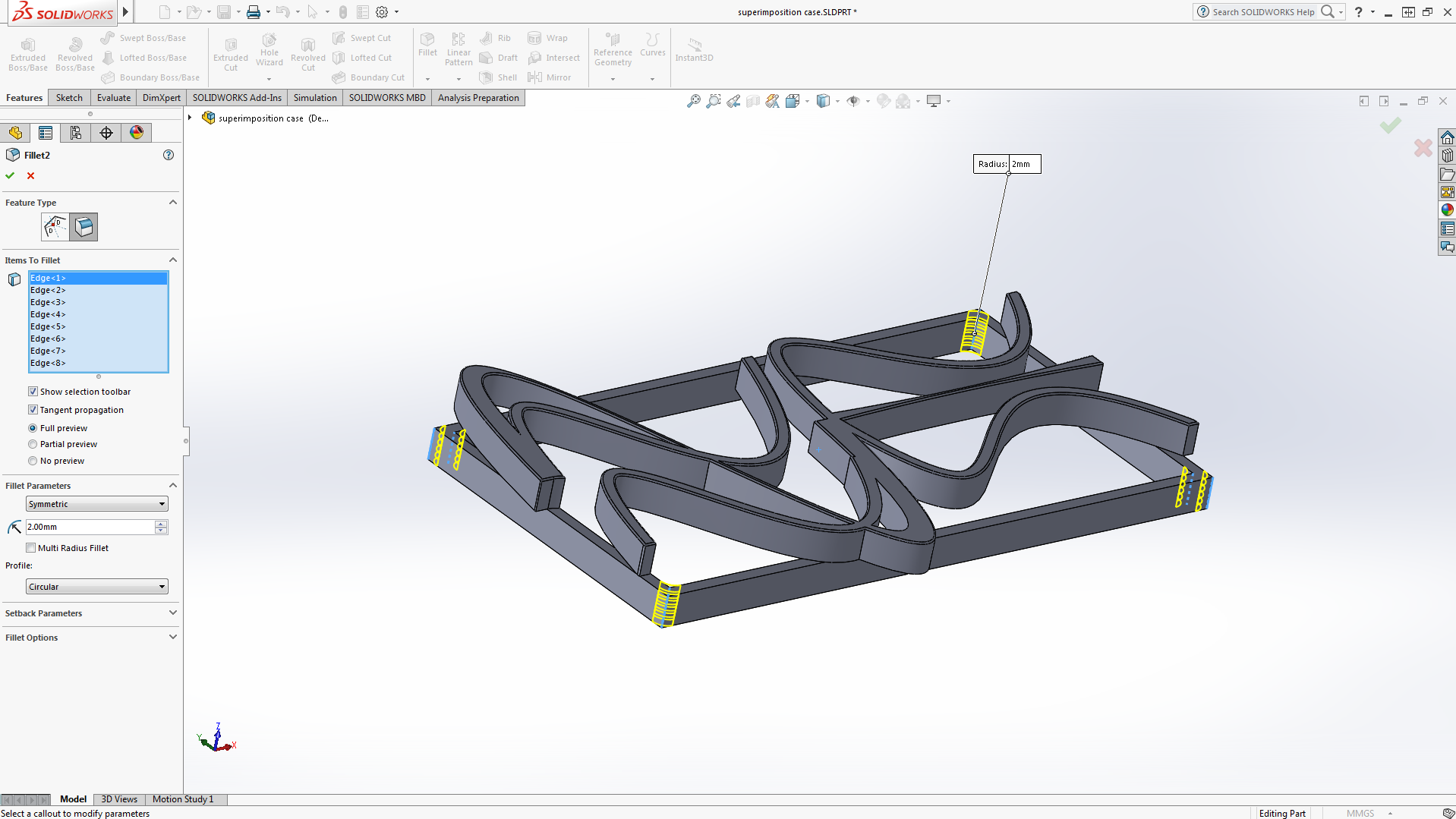
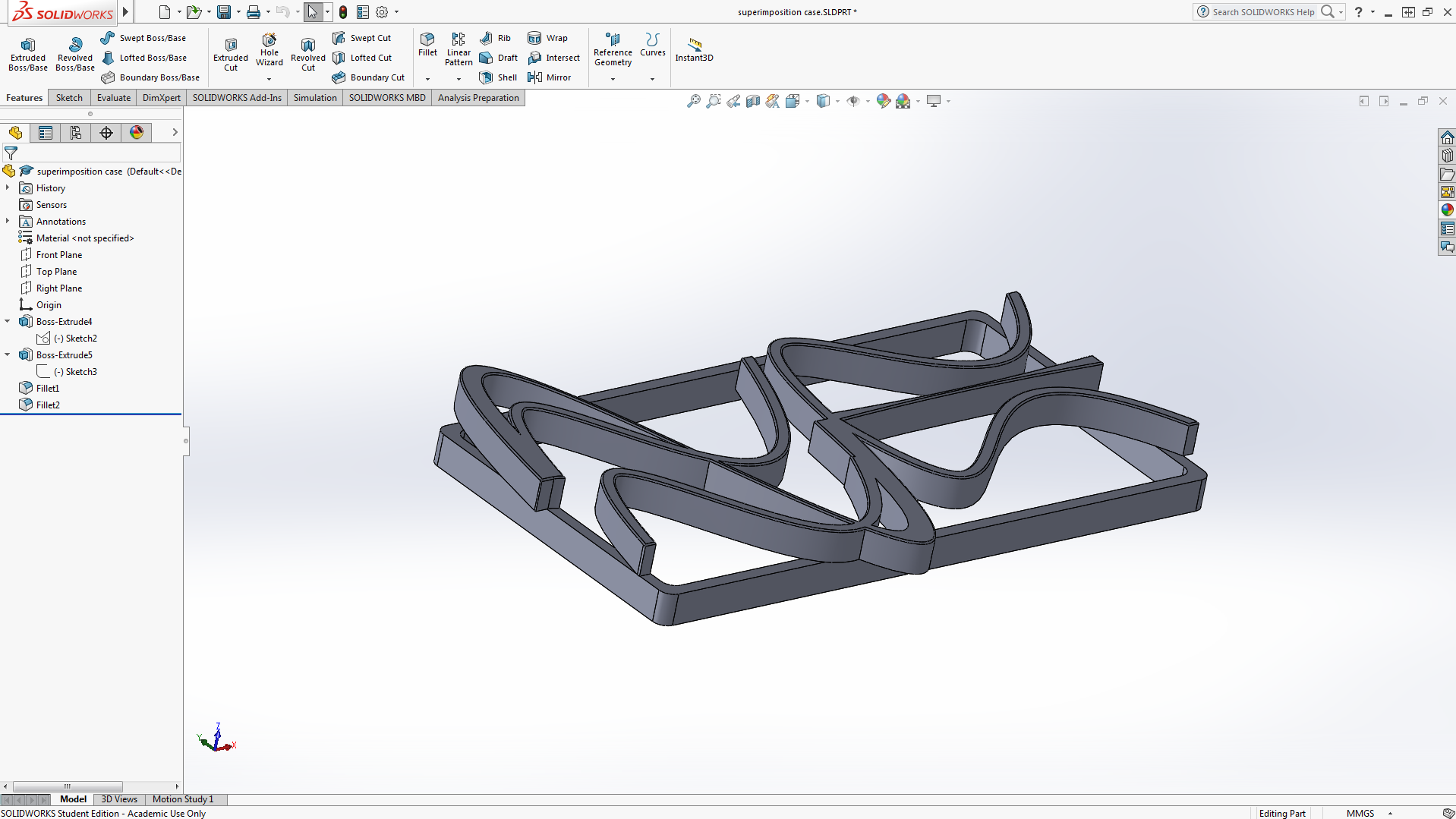
Select the edges of all the sound wave patterns and select the fillet feature with a radius of 0.25mm. Then select the inner and outer corners of the rectangle and fillet with a radius of 2mm.
Transfering Files From Solidworks to Cura
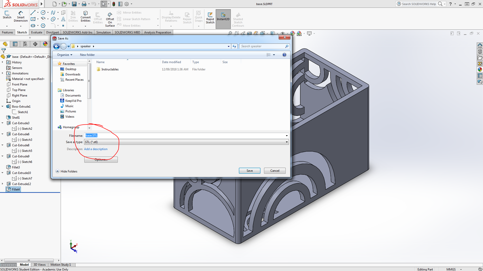
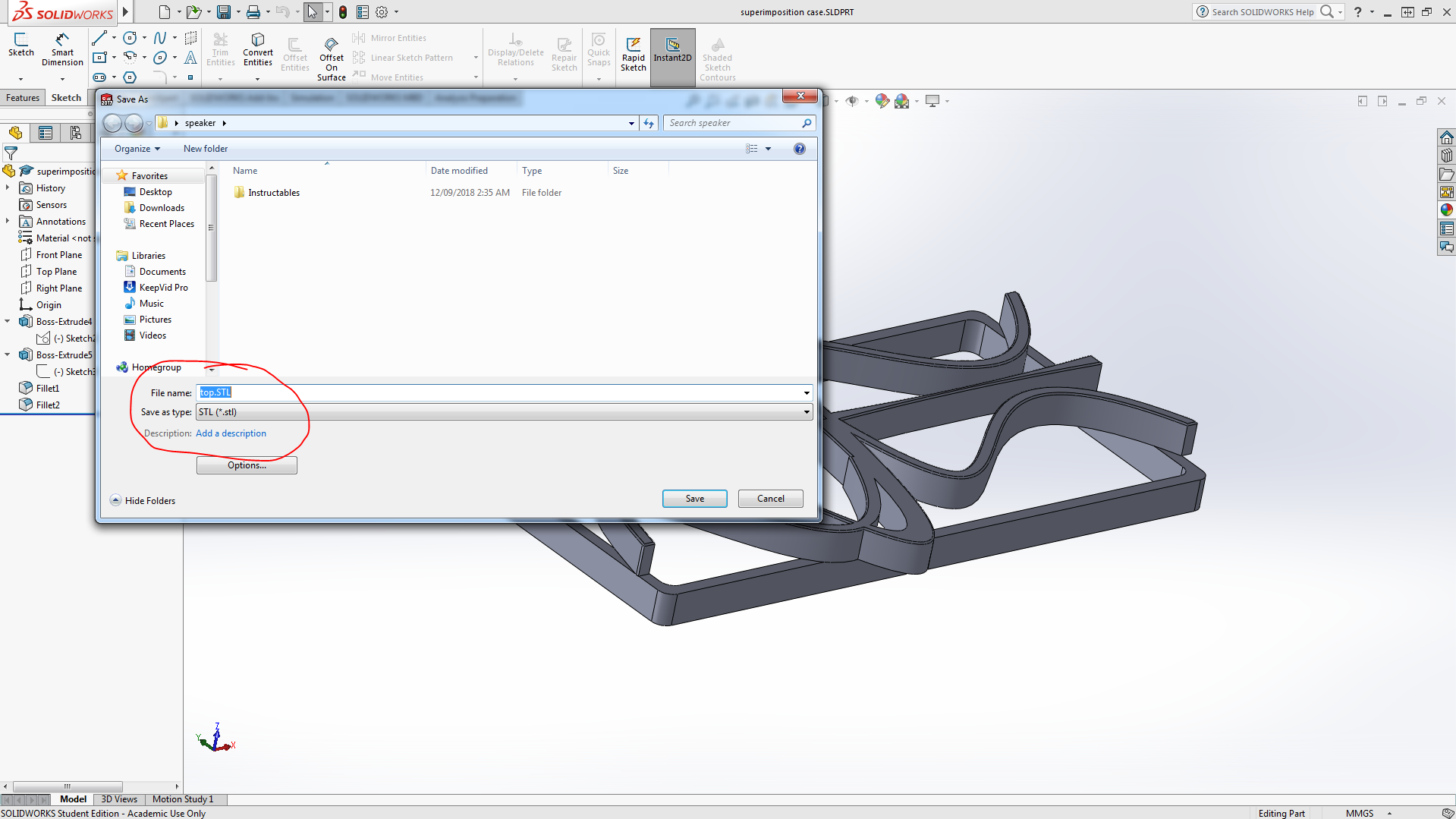
Once you have finished modeling the parts on Solidworks, go to file, save as and save the file as an STL file. Do this for both the top and base parts.
Printing
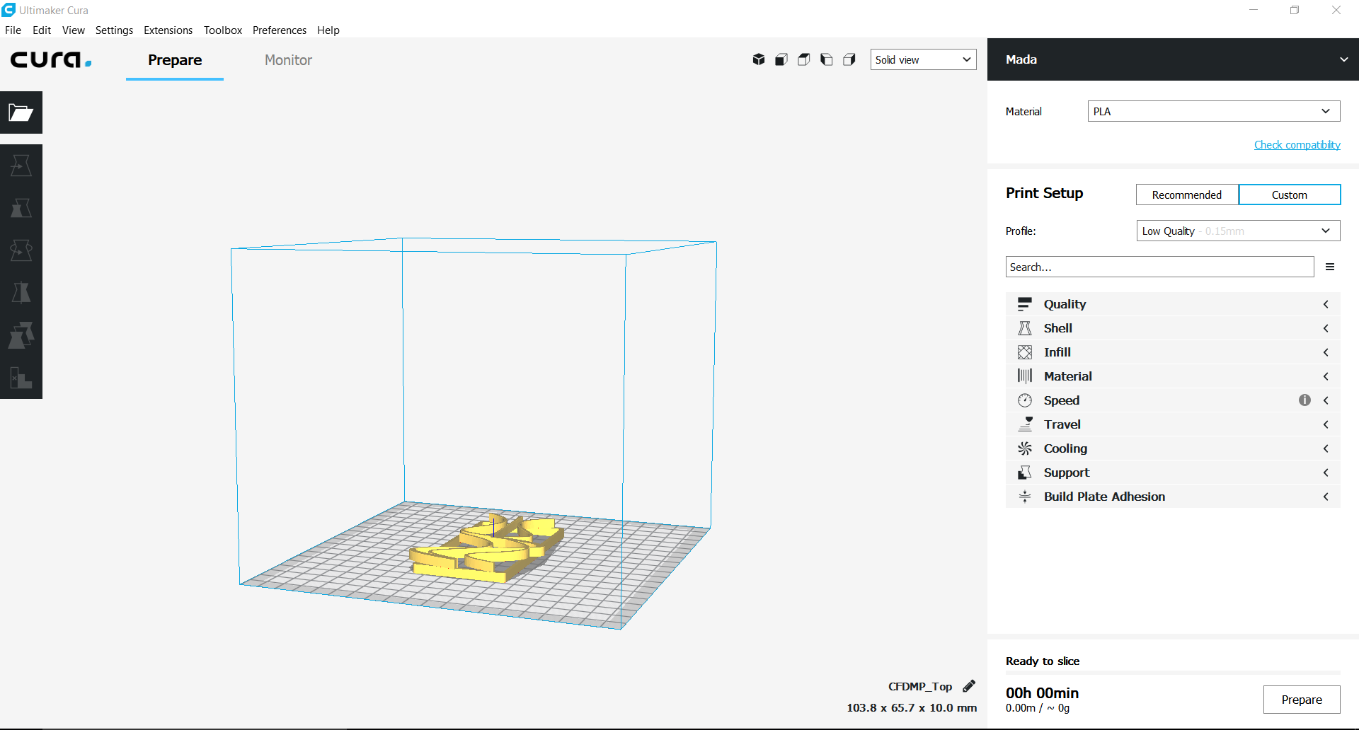
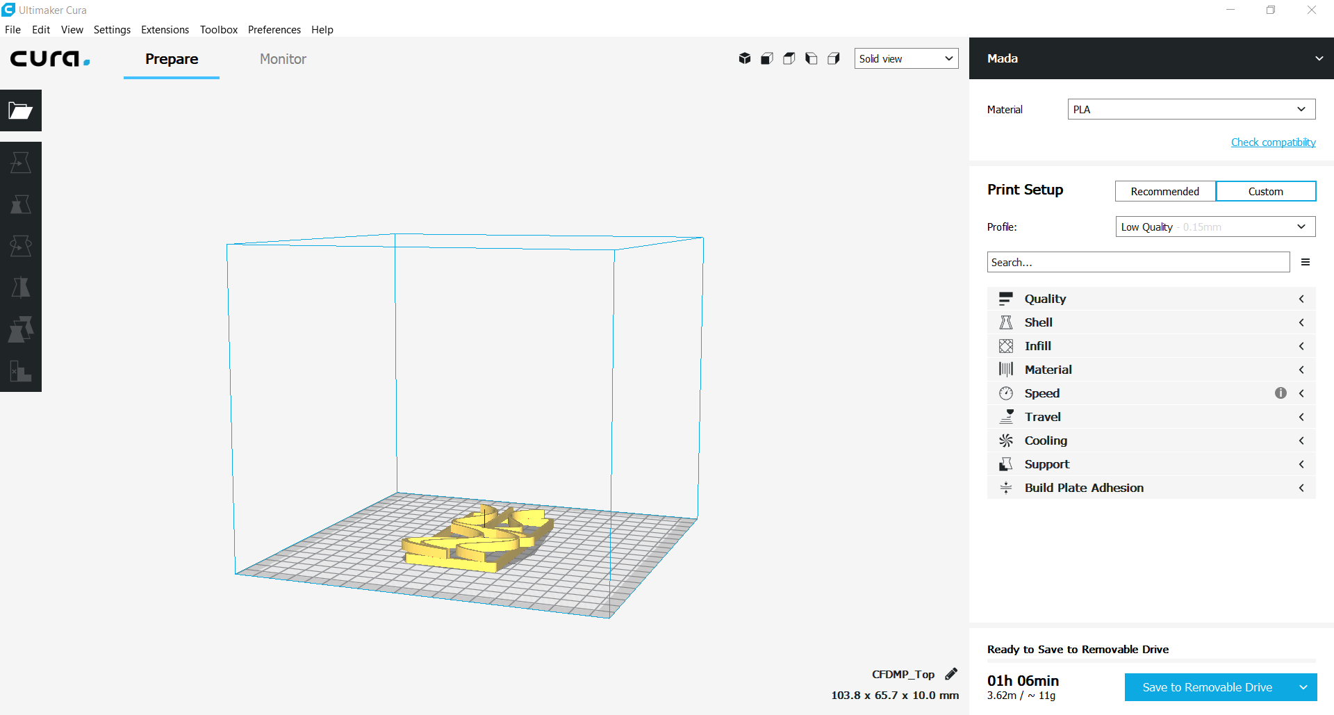
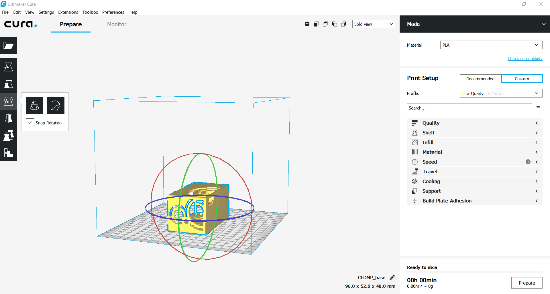
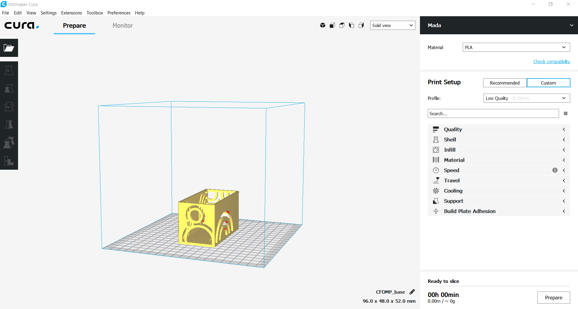
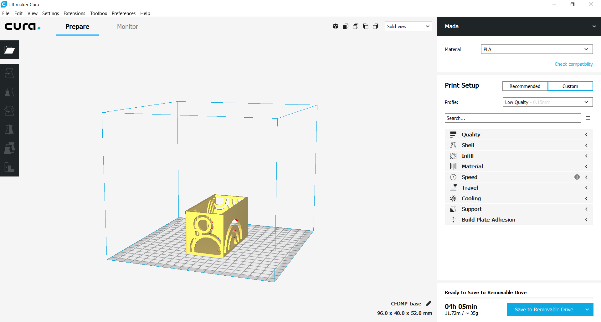
Start by opening the STL files on cura. Then ensure the part is positioned within the boundaries of the bed. Preferably in the centre. Then click prepare in the bottom right corner of the program. Then finally, Save to removable disk.
Some parts may initially be positioned in an orientation that is not ideal. To rotate a part, click on the part and rotate by pulling the circles that appear around the part.
Once you have prepared and saved the slice on the removable disk, insert the removable disk into your printer and start printing!