Super Pitendo: Raspberry Pi 3b+ Retro Console Build
by ncarley007 in Circuits > Raspberry Pi
2284 Views, 9 Favorites, 0 Comments
Super Pitendo: Raspberry Pi 3b+ Retro Console Build
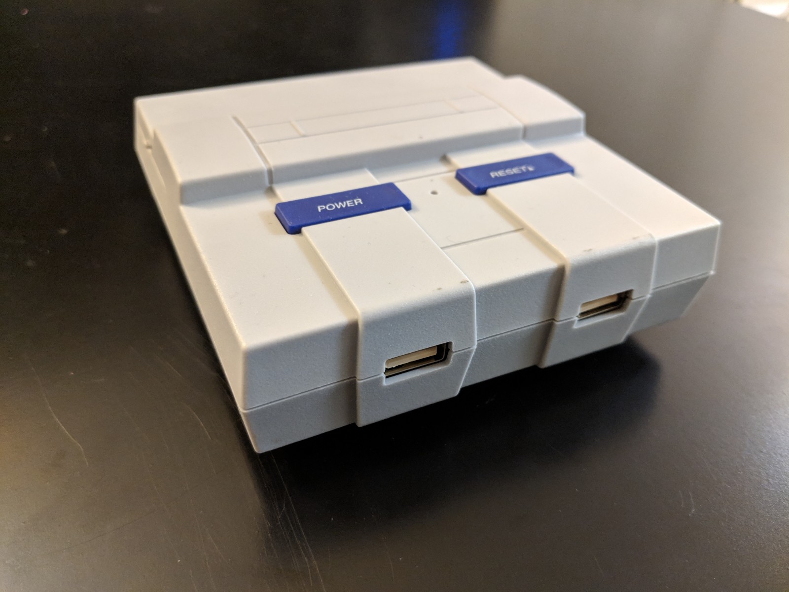
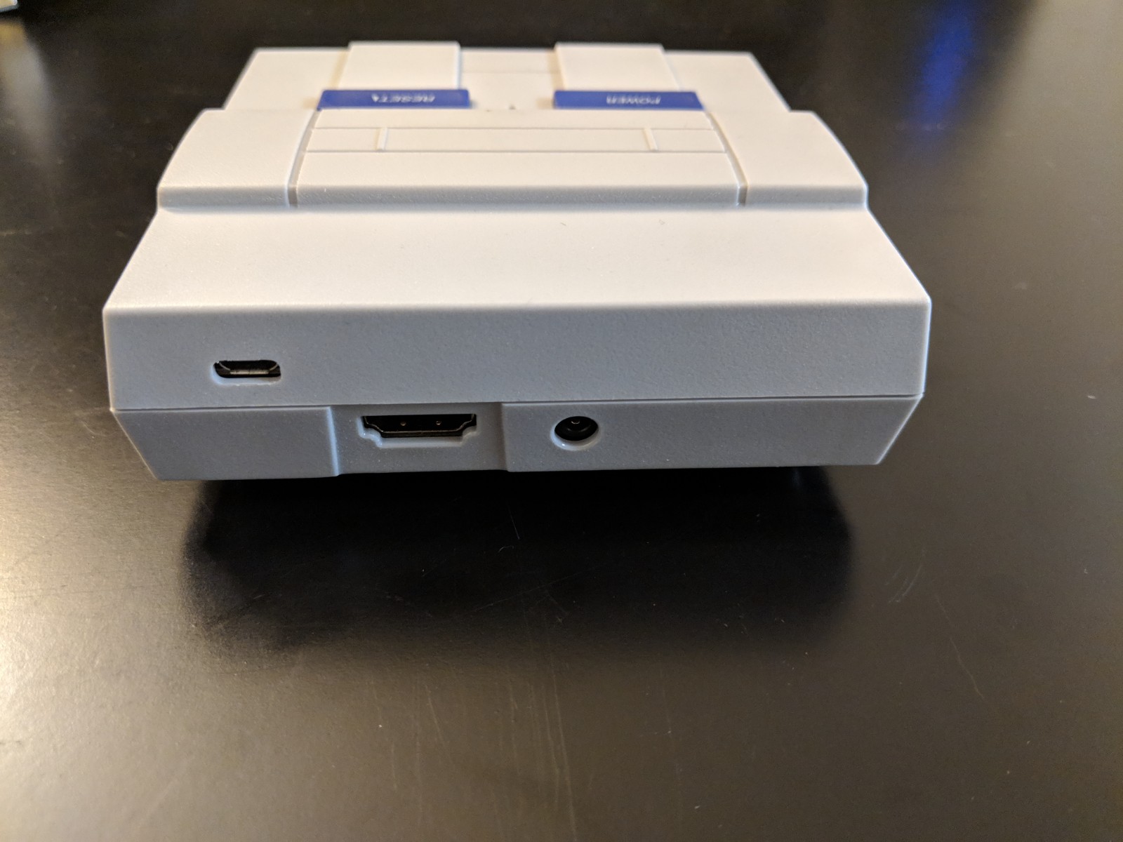
Hello! During the last holiday season, and again this year, I heard my siblings talk about how cool they thought the retro consoles coming out are. BUT, I also heard of their frustrations at how expensive they were and the difficulty of finding them in stock. To solve this I decided to make them a home made retro console, the Super Pitendo!
During this instructable, I'll cover the hardware used (very important for those N64 games) as well as some software configuration to help get the games running smoothly. You will need to find the games on your own.
Hardware
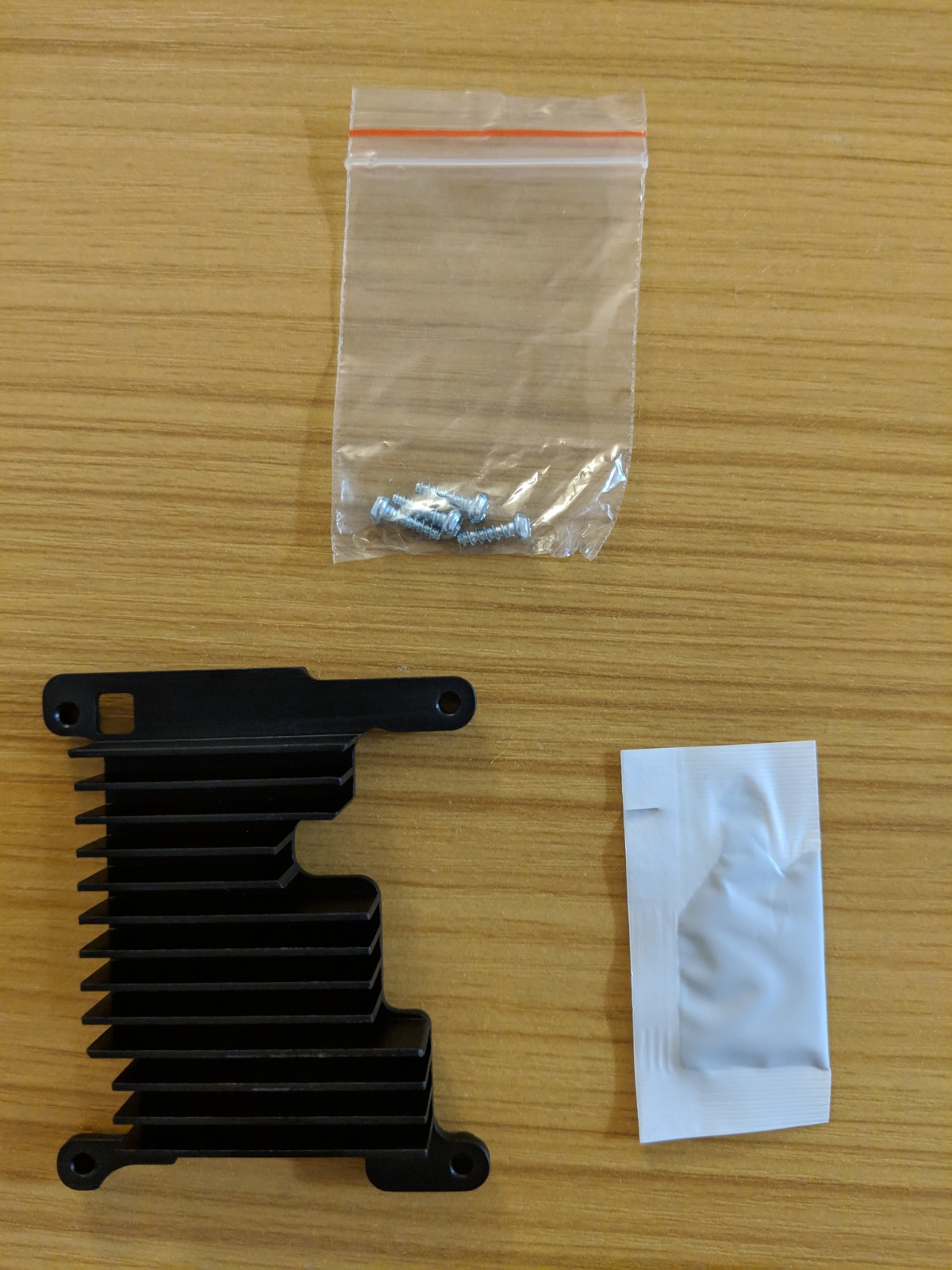
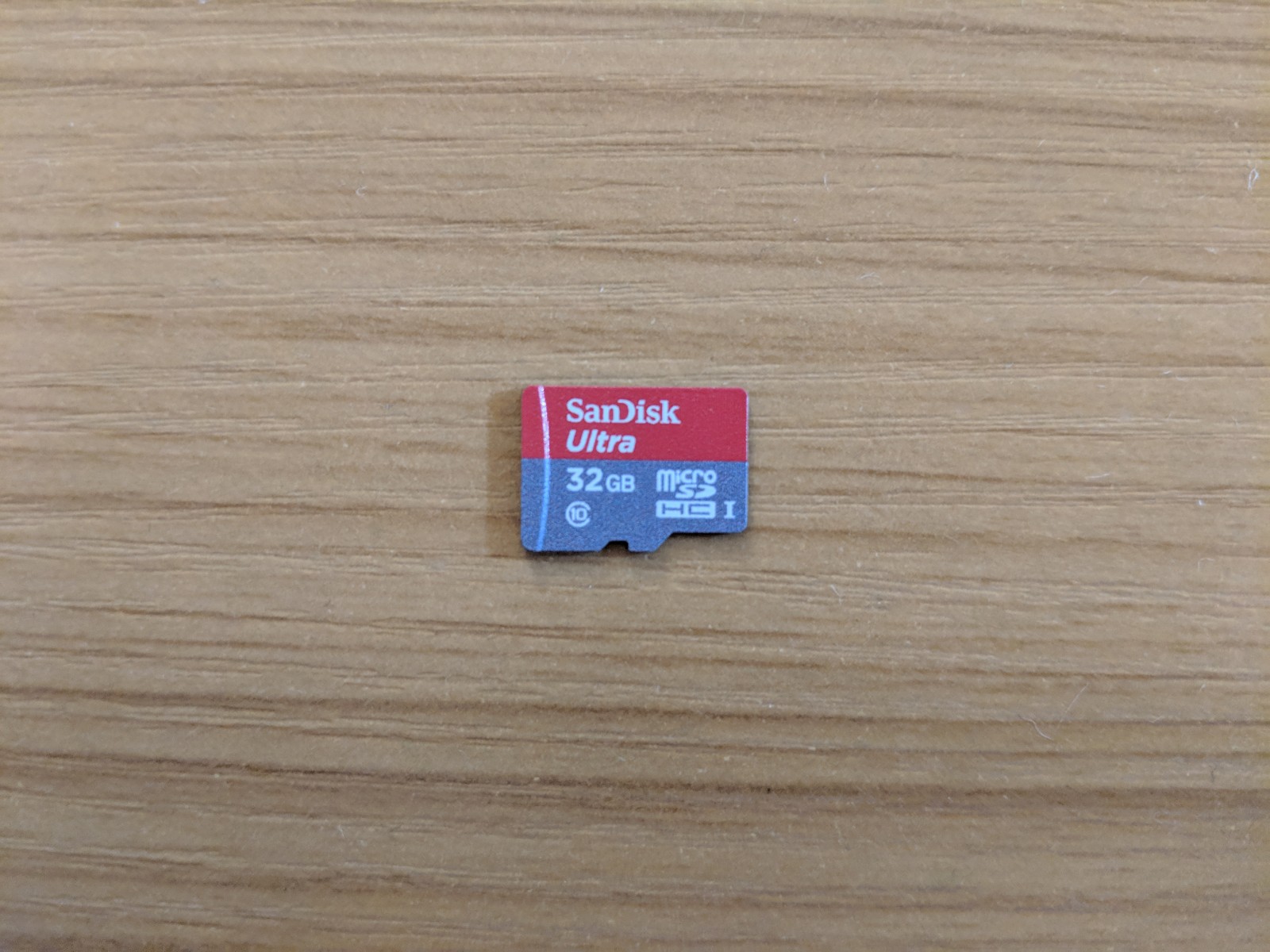
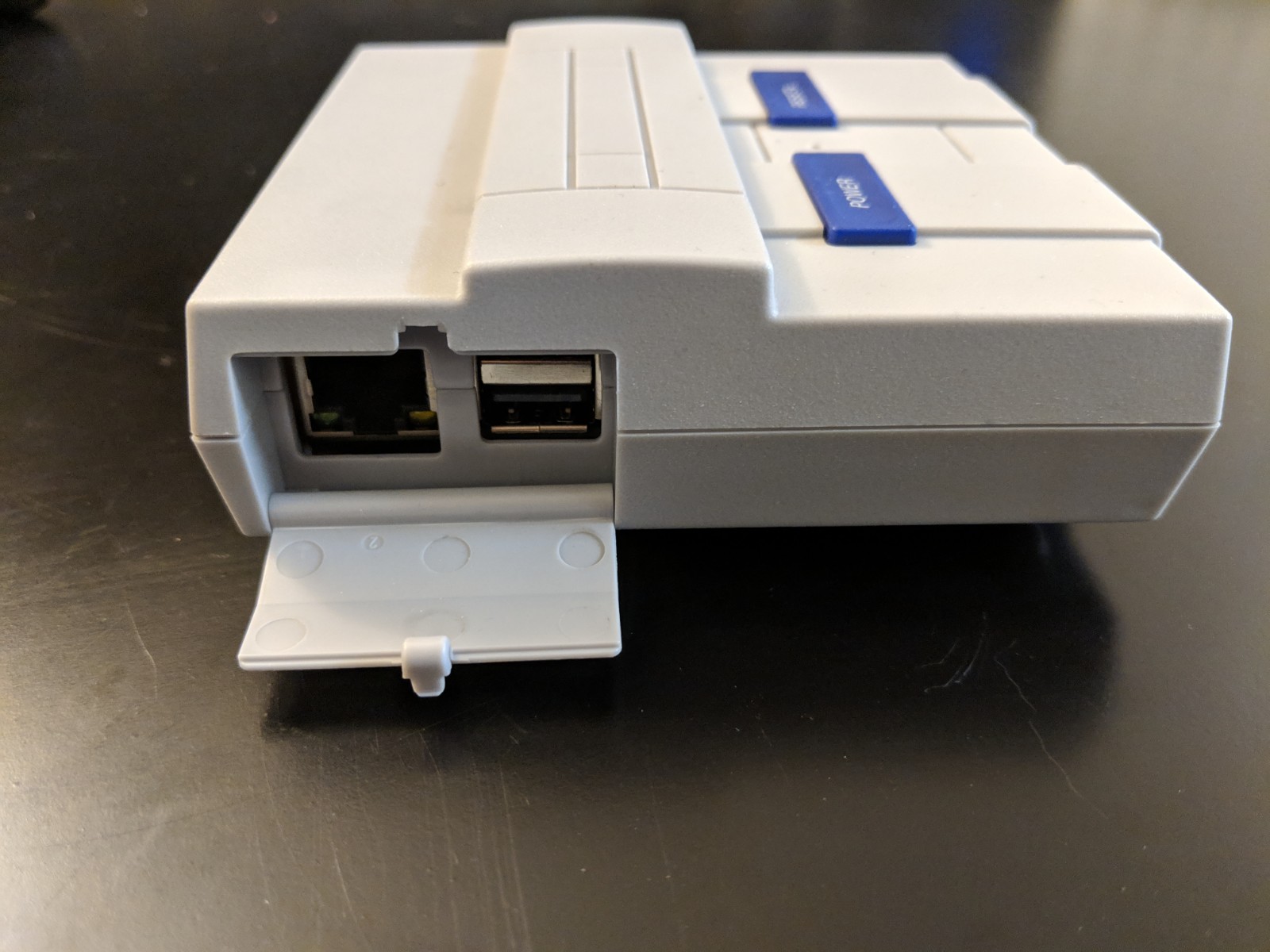
Below is the list of hardware for the Super Pitendo. All items were purchased through Amazon at the below links. The power supply is particularly important for this build for it's 5.25V rating. I will go into more detail on the significance later on.
Computer: Raspberry Pi 3B+
Case: SNES Raspberry Pi Case with Front Facing Ports and Functioning Buttons
Controller: 8 Bitdo Bluetooth SNES Controller
SD Card: SanDisk Class 10 32GB SD card
Heat Sink: Aluminum Full Board Heat Sink for Raspberry Pi 3B+
Power Supply: 5.25V 2.4A Keyestudio Power Supply
HDMI Cable: Amazon Basics 6ft
Assembling the Hardware
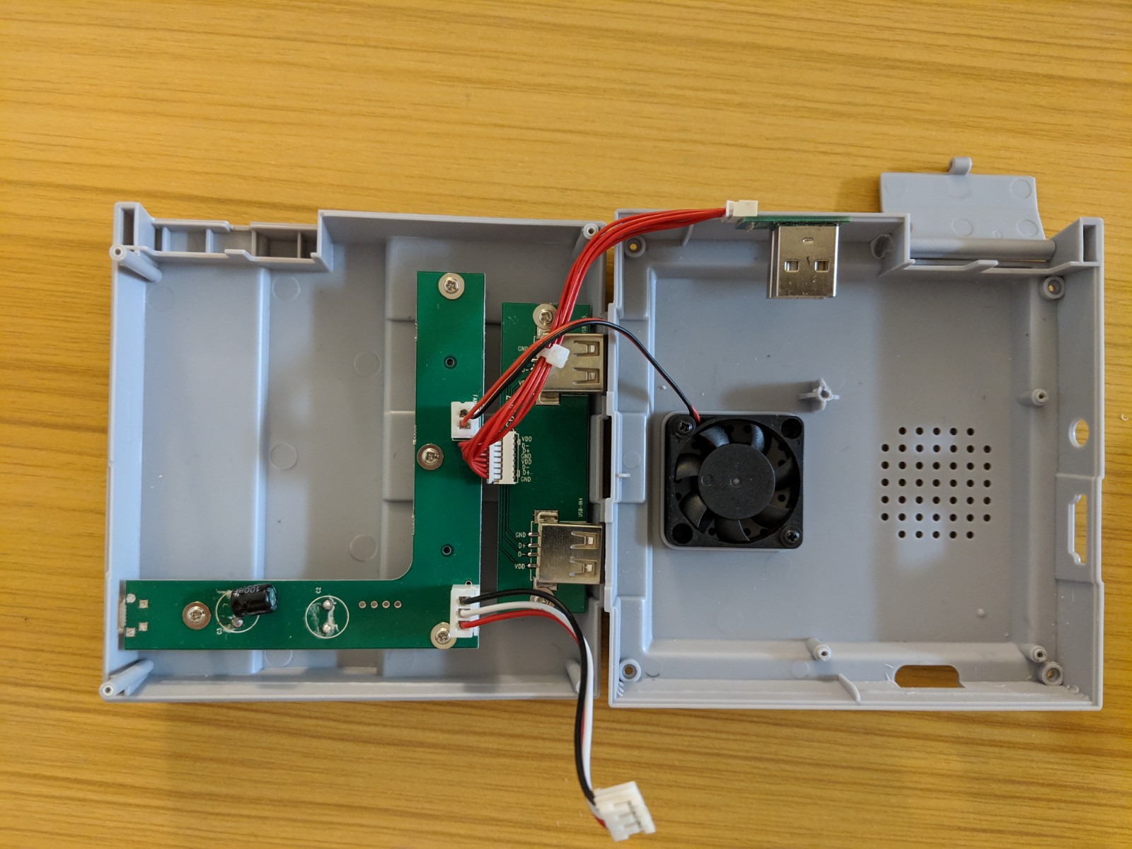
1. Using the screw driver provided with the SNES case, open the clam shell, Image 1
a. Inside this case you will see a small fan mounted to the bottom shell, I would suggest you tighten these screws to reduce shaking of the fan while it is running
b. A board mounted to the top shell. This board handles the power input for the case and routes the power through a push button controller. This push button controller handles the "Power" and "Reset" buttons on the case as well as the power connects for the fan and the Raspberry Pi.
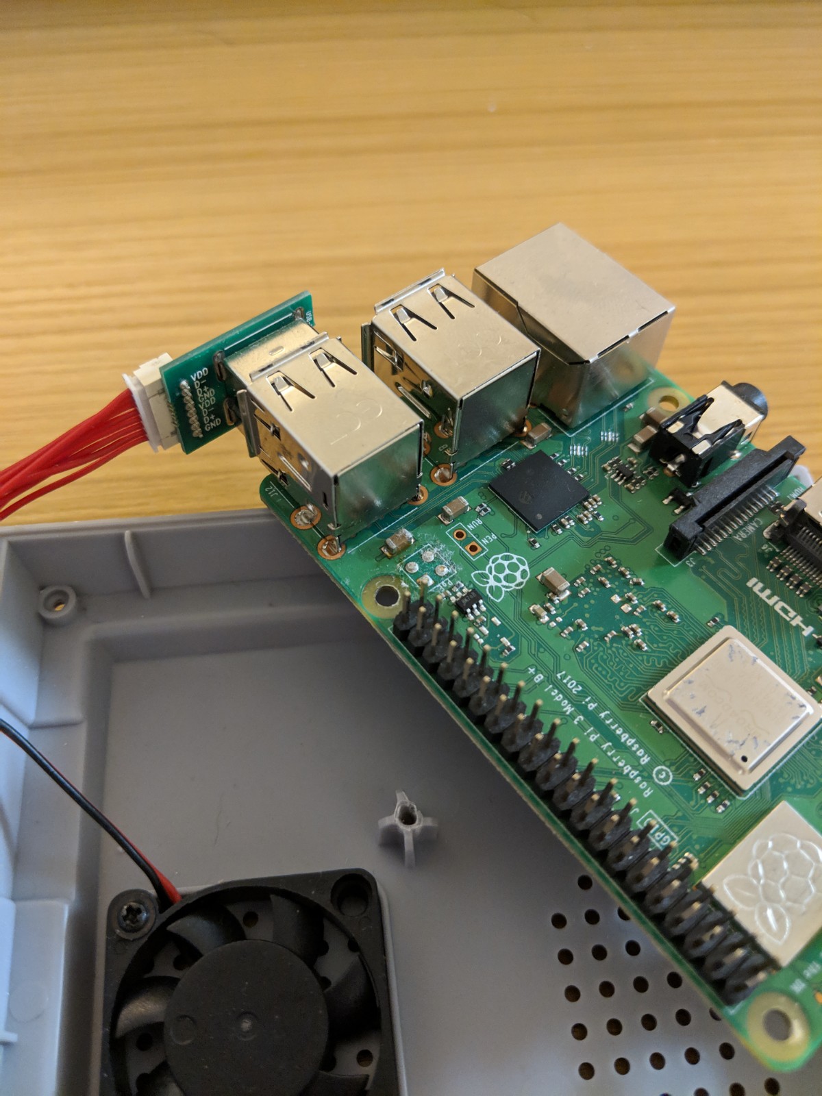
2. Take your RPi and attach the USB extenders as shown in Image 2
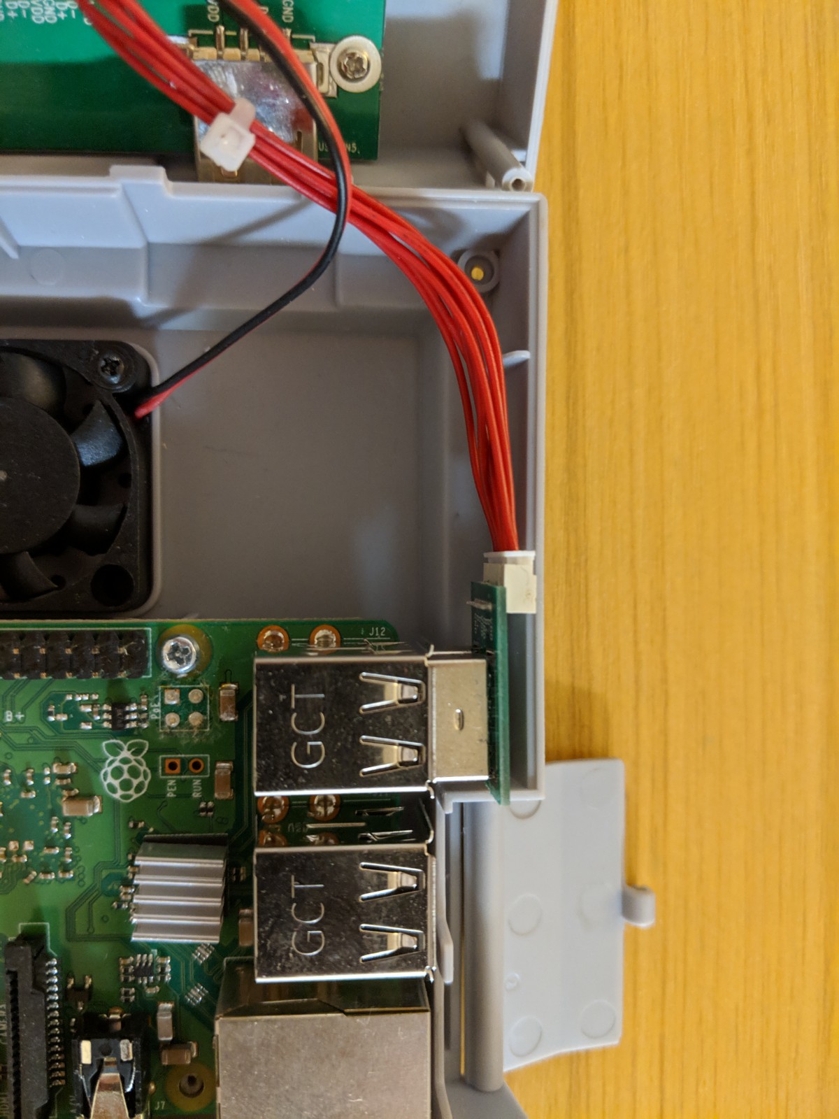
3. Place RPi inside the case so that the 4 holes of the Raspberry Pi board line up with the mounting holes on the case as shown in Image 3.
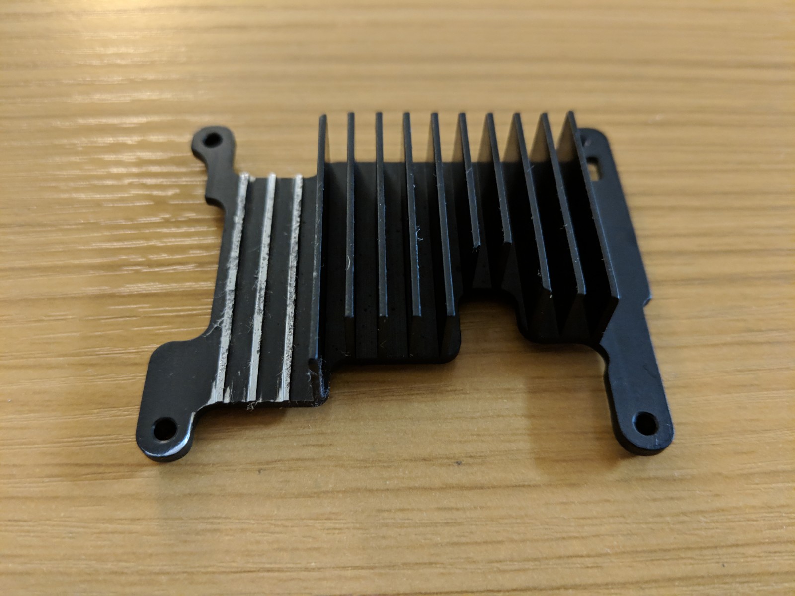
4. The heatsink has 3 fins that will get in the way of the SNES case closing to fix this we need to remove the last 3 Fins as shown in Image 4. I used a standard metal Saw and pliers to remove the 3 fins.
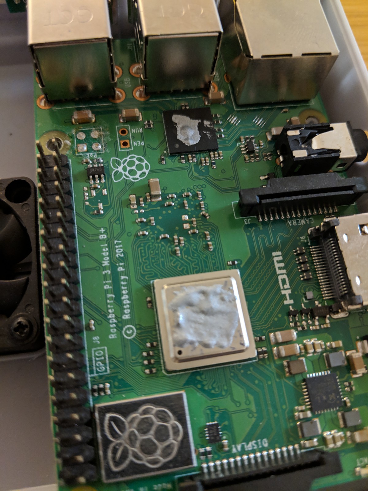
5. Use the thermal paste included with the heatsink and place a small drop on both the RPi 3B+ processor (silver square) and the USB/Ethernet chip (small black box near the USB ports) as shown in Image 5.
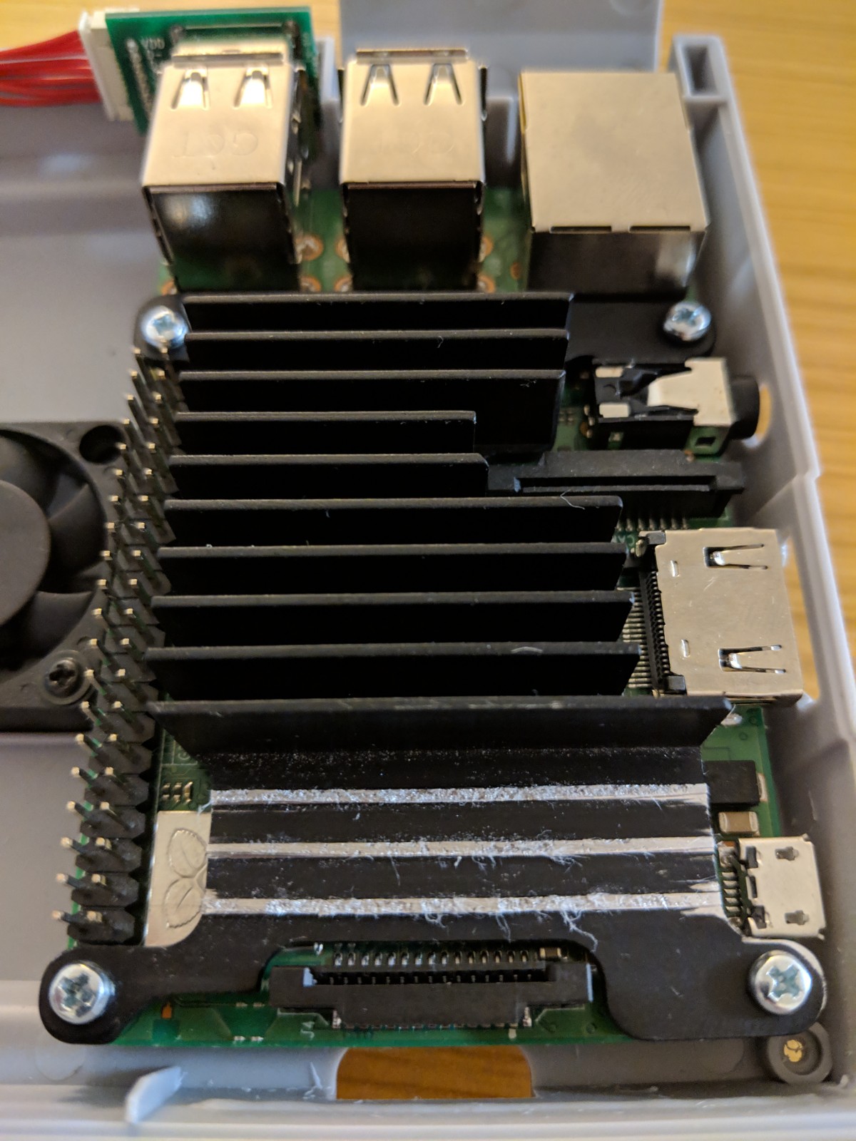
6. Place the heatsink onto the RPi, be careful to minimize the amount of sliding. Using the 4 screws provided with the heatsink, attached the heatsink through the RPi and onto the case as shown in Image 6.
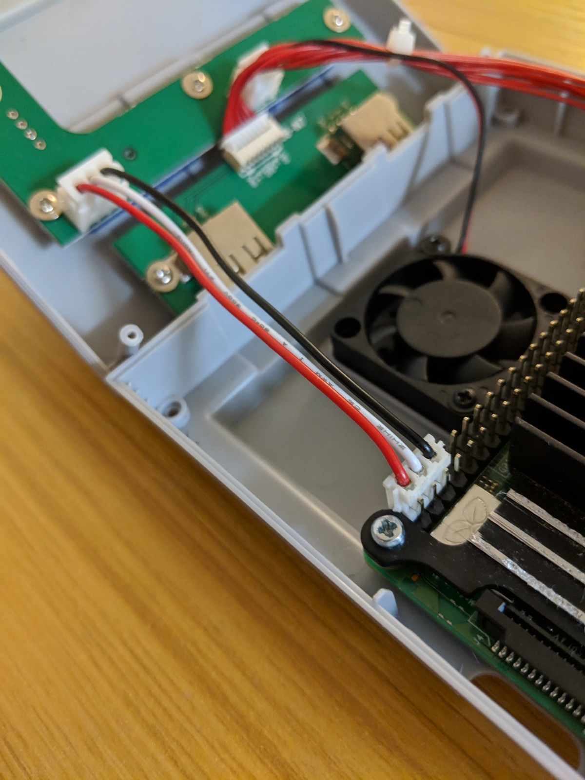
7. Attached the 3-pin Power and Ground connect from the top portion of the case onto the bottom-outside pins of the RPi as shown in Image 7. This connects the power input from the board in the top case to the RPi.
The Power Supply and Under-Volting
I mentioned in the beginning that the specific power supply I choose was critical. During the course of this project I actually purchased 5 other power supplies, including the official power supply. But ran into under-volting issues when playing higher demand games such as N64 games.
So what is Under-Volting? The RPi runs off of a microUSB power supply which typically delivers 5V. When the current pulled by the RPi increases, the 5V supply may momentarily decrease, or "Droop", below 5V. When the input voltage droops below 4.7V (officially the threshold is 4.63±0.07V) the processor on the RPi will throttle itself which can cause stuttering or even crashes during gameplay.
To make matters worse, the PCB in the top portion of the case adds additional series resistance to the power supply. As the RPi pulls more current, this series resistance lowers the voltage on the power supply before it evens gets to the RPi.
So how does this specific power supply solve this issue? The Keyestudio 5.25V power supply is just that, a 5.25-Volt supply. The extra 0.25 may not seem like much but this additional voltage corrects the voltage drop that occurs through the PCB in the top shell. When the RPi is pulling a full load, the voltage at the input of the RPi GPIO pin is ~5.03V which means no more stuttering gameplay!
Software - Retropie 4.4
Download the RetroPie image: https://retropie.org.uk/download/
Download Windisk Imager: https://sourceforge.net/projects/win32diskimager/f...
1. Using Windisk Imager to install the RetroPie image onto your SD card
2. Once complete, install the SD card into the Raspberry Pi
3. On your first boot be sure to expand your file system:
a. exit out of retropie by pressing "F4" on your keyboard
b. type "sudo raspi-config"
c. select "Advanced Options" then "Expand Filesystem"
d. when complete, reboot
Software - Optimizing
1. Plug the SD card back into your computer and open up the drive labeled "boot"
2. Open the .txt file labeled "config"
3. at the bottom of the text file include the below statements, note a few settings will void your warranty on the raspberry pi.
total_mem=1024
arm_freq=1450
gpu_freq=560
core_freq=600
sdram_freq=525
sdram_schmoo=0x02000020
over_voltage=2 #this voids your warranty on the raspberry pi
sdram_over_voltage=3
force_turbo=1 #this voids your warranty on the raspberry pi
avoid_warnings=2 #this voids your warranty on the raspberry pi
Final Comments
This is my setup on the Super Pitendo, I hope this helps in your setup and configuration!