Sunriser: a Completely Custom Keyboard With a Volume Knob!
by crashl1445 in Circuits > Electronics
4826 Views, 44 Favorites, 0 Comments
Sunriser: a Completely Custom Keyboard With a Volume Knob!


.jpg)
I decided to completely custom keyboard for my SIDE project in my engineering class taught by Ms. Berbawy at Irvington High School. This board features a TKL minus F-row layout, rotary encoder that serves as a volume knob, and support for an OLED display.
The name "Sunriser" is a play on the name of the keyboard Sunsetter which was designed and manufactured by Charue Design [see pic 3], which was my first introduction into the hobby of custom keyboards. The board served as a huge inspiration for this project not only because of the name, but also because I wanted to be able to use the extra badges I owned from participating in their group buy for this project.
- Shout out to Duv Basil for help with the code
- Shout out to Ms. Berbawy for believing in me when no one else did and for supporting me through some rough times
- AND CHARUE DESIGN (the team and community) for giving me the opportunity to enter this new hobby and for serving as the inspiration for this project
Supplies
.jpg)
.jpg)
.jpg)
.jpg)
.jpg)
.jpg)
.jpg)
.jpg)
.jpg)
Materials you will need:
- PCB
- [pic 1 and 2]
- Microcontroller
- [pic 3]
- Diodes
- [pic 4]
- Reset Switch
- [pic 5]
- Key Switches
- (preference)
- [pic 6]
- Rotary Encoder
- [pic 7]
- Knob
- [pic 8]
- Stabilizers
- [pic 9]
- Keycaps
- (preference)
- Filament
- (preference)
- Acrylic
- Silicone
- M2 Screws
- M2 Inserts
- M2 Standoffs
Tools you will need:
- Soldering Iron
- Solder
- Screwdriver
- M2 Allen key
- Pliers
- Flush cutters
- 3D Printer
- Laser Cutter
- Super Glue
Software:
- Fusion 360
- Adobe Illustrator
- KiCad
- QMK
- Respective Programs for 3D-Printer & Laser Cutter
The PCB!
.png)
.png)

.png)
.jpg)


- I Used KLE to plan and create the desired keyboard layout. I also added optional layouts and key layouts (color-coded).
- [pic 1]
- Then I moved over to KiCad, a PCB design software and through available keyboard libraries, I created my PCB schematic by using a switch matrix and diodes to optimize the number of rows and columns used and assigned those rows and columns to pins on the Elite-C microcontroller.
- [pic 2 and 3]
- I added the switch portion of the encoder to the matrix and assigned the two other pins to the MCU
- I also decided to add support for an OLED display, as shown here, but I decided not to use it for my first iteration of this project.
- [pic 5]
- Don't forget to create a circuit that uses a push-button switch to short the reset and ground pins on your MCU, without needing to manually do so
- The PCB was then created by placing the component footprints and using "Free Router" to route the traces
- [pic 4]
- Make sure to add stabilizer holes (if your footprint does not support it)
- I then created and added a custom anime japanese car weeb silkscreen that I made in Adobe Illustrator!
- [pic 6]
- Once I was ready to print the PCB I used JLCPCB to get my PCB manufactured.
- [pic 7]
The Case Design
.png)
.png)
.png)
.png)
.jpg)
.png)
.png)
.png)
.png)
- I created the case in Fusion 360
- pink- top case
- green- bottom case
- red- PCB
- translucent dark- acrylic plates
- [pic 1] overall view
- [pic 2] bottom view of the top case
- [pic 3] top view of the bottom case
- [pic 4] bottom view of the bottom case
- I put the source information of the layout from KLE into a plate generator to create SVG files to create a compatible plate for the layout I chose
- (don't forget to overlap the optional layouts over the main part off the layout before you put it into the plate generator)
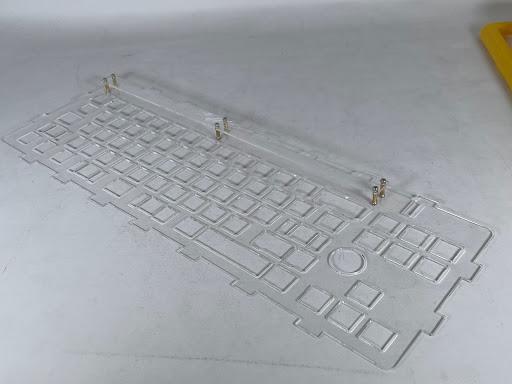
- I imported this SVG into Fusion and created a 1.5mm thick plate.
- I edited the plate to include tabs, that will eventually serve as gaskets for a softer typing feel as well as to suspend the plate and PCB between the top and bottom case
- [pic 5] (from keyboard university)
- Receiving/Female tabs were designed as a part of the case that has spacing to accommodate the thickness of the plate due to both the top and bottom gaskets made from the silicone rubber sheets
- [pic 2 and 6]
- I used the dimensions from the finished PCB to size the case to my liking
- I made sure the holes for the knob, USB port, badge slot, navigation cluster, arrow keys, alphas/modifiers, and keycaps were given attention.
- [pic 7 and 8]
- A chamfer was added under the nav cluster due to the lack of clearance from the case being too close to the keycaps
- This is also where I created a slot similar to the one from the "Sunsetter" to accept the badges from my other board.
- The case was also split, with male and female tabs to connect the two halves
- [pic 9]
- Due to the size of the keyboard, I was unable to fit the entire case on the build plate of a Prusa Mk3+
- I also designed access to the bottom of the board with an acrylic plate. It is meant to a be pleasant and aesthetic window to be able to view the solder job, components, and PCB silkscreen from underneath
- [pic 4]
- I also designed an accent plate, where I would be able to offset a thin acrylic plate over the diodes that I'd be able to engrave with my designs!
Acrylic Plates
.png)
.jpg)
.jpg)
.jpg)

- To create the plates I downloaded the plates I had already designed in Fusion 360 as an SVG file.
- Next, I headed to Adobe Illustrator to edit/add graphics that will be engraved or rastered including my name, contact info, keyboard name, and sun graphic to go along with the name.
- [pic 1] the completed adobe illustrator file ready to cut
- red- cut lines
- blue- engrave lines
- black- raster lines
- Then, I tested the graphics by cutting the plates out of wood
- [pic 2] wooden test cut for the bottom plate
- [pic 3] wooden test cut for the switch plate
- After I was happy with the results, I laser cut them out of 1.5mm thick acrylic sheets
- CAUTION
- [pic 5] (thin acrylic can be fragile and crack)
- 2+ mm acrylic is way too thick for the stabs to fit with no issue
- Then I assembled the switch and accent plate with M2 screws and standoffs
- [pic 6]
3D Printing the Case


.jpg)


- 3D Print the Case in PETG for extra strength or PLA for better color options, I chose PETG
- Open the STL files in the slicer. I used the settings below which might change depending on your printerfo1':
- 20 % infill (may vary)
- Supports everywhere
- CAUTION: Note the orientation of each print
- [pic 2, 4, and 6]
- I used the Prusa Mk3+ and so, had to print in 3 batches
- [pic 1] both bottom halves
- [pic 3] left top half
- [pic 5] right top half
- Final Prints!!
- [pic 6]
- BONUS [pic 8 and 9] Badge test fits!
- LOVE YOU CD community
Stabilizers!
.jpg)
- Here I followed the stabilizer's included instructions to lube and install the stabilizers into the PCB
- more advanced tutorial for lubing and tuning stabs
Soldering

.jpg)
.jpg)


- Through-hole solder the MCU sockets (NOT THE MCU) into the PCB while it is facing down
- [pic 3]
- (make sure you clip the protruding ends that face up) this is necessary for the switch above it to have enough clearance to sit flush onto the PCB)
- SMT solder the diodes onto the top half of the PCB
- [pic 4]
- SMT solder the reset switch
- Then with the acrylic plate above the PCB click in all the switches through the plate (in your desired layout) and make sure the legs fit into the PCB.
- [pic 5]
- When you have all of your switches in, through-hole solder every switch on the board
- Next, solder in the rotary encoder
- Don't forget to solder resistors, headers, and/or wires for the OLED if applicable
- Finish off the board by soldering the Elite-C to the microcontroller sockets you soldered in step 1
- [pic 2] is me :)
- [pic 1, 6, and 7] finished (PCB plate switch combo) product
Programming
- The easiest way to create the program for this keyboard is to use QMK
- (QMK is the easiest and most widely used keyboard software)
- I used the website "Keyboard Firmware Builder" to start building the basics of the firmware
- This website takes a layout combined with some settings to create a QMK program for any custom keyboard. Even though the website is outdated, it can still work.
- The website asks to input:
- a switch layout imported from KLE
- a wiring diagram of my switch matrix
- the assigned pins to each row
- diode direction
- MCU selection
- the keymap itself
- Next, I had to download the source files because the website is outdated and was based on older QMK builds. This meant that I had to edit each individual file to the standard formatting used by recent QMK builds by referencing default keymaps and files of current keyboards on the market as well as the QMK docs.
- Not to mention, I had to also add in support for the rotary encoder as explained by this part of the QMK write-up.
- Then using the QMK environment, I compiled the newly adjusted files and flashed them to the MCU using the QMK bootloader.
- I continued to edit, refine, and tweak the firmware to my liking using features such as unique keycodes, layers, and much more, all available in the vast library of QMK support.
Assembling the Case Pieces
.jpg)
.jpg)
.jpg)
.jpg)
.jpg)
- Clean up and remove the supports fro the prints
- Re-drill the standoff holes if necessary
- Sand down and clean up edges
- Fit the halves into each other (Dremel/Sand if needed)
- Install the M2 inserts into the top and bottom case (method based on tolerances)
- [pic 1]
- Method 1 (If tighter)
- Heat the inserts via a heat gun and
- Press fit the hot inserts into the holes
- Method 2 (If looser)
- Put a drop of super glue in the standoff hole
- Use pliers to push the standoff into the hole
- If necessary use liquid super glue around the edge of the standoff/hole
- Cut out the silicone pieces into gasket tabs sized by the indents in the case
- Install gaskets
- Set up the bottom half facing up
- add super glue to each tab indent
- Apply the silicone gaskets to each indent
- [pic 2]
- Place the acrylic switch plate facing up
- Add super glue to each of the tabs
- Apply the silicone gaskets to each tab,
- [pic 3]
- make sure there is no overhanging silicone
- Let them dry
- Test fit the top and bottom halves with the plate ONCE DRY
- [pic 4]
- Fit in and screw the "Sunsetter" badge in
- [pic 5]
Final Assembly


- Place the PCB plate switch assembly into the bottom case making sure:
- the tabs fit into the indents and each one makes contact with the silicone gaskets
- the USB port from the microcontroller fits into the USB slot in the case
- Fit the top case over the PCB, sandwiching the plate.
- Screw in the bottom case into the top case from the bottom using, appropriately sized M2 screws
- Then with the board flipped over, screw the bottom acrylic panel into the bottom case
- Then dress up your keyboard with your favorite keycaps
- Done :)
Conclusion
.jpg)
.jpg)
This project taught me the basics of programming, 3D printing, laser cutting, and appropriate software. This keyboard, hobby, and class pushed me through some tough times, taught me new skills, and showed me a creative side of myself that I never knew existed! Thank you to everyone who helped me! Until my next project or post, peace everyone. ✌️
P.S. Message me on discord "Crash#8751" if any of you need help on a similar project :)