Subway Status at a Glance
by MovingBrands in Circuits > Gadgets
3133 Views, 47 Favorites, 0 Comments
Subway Status at a Glance
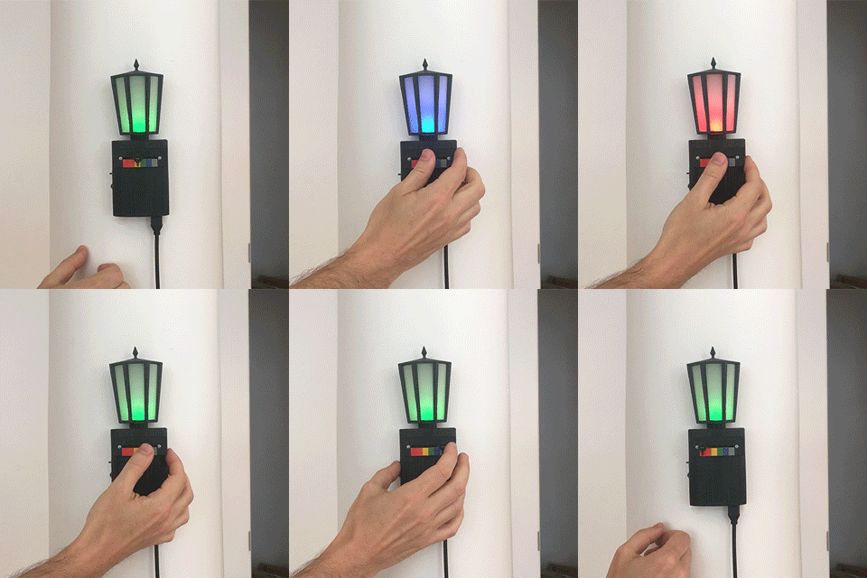
The subway tracker is a wifi lamp that lets you quickly keep track of whether your subway is on time or delayed – basically a physical version of MTA's service status widget. You can change which line you want to know about by moving a slider.
This instructable shows you how to make a tracker for the NYC subway, with some direction for how to adapt the code for London or other cities.
How It Works
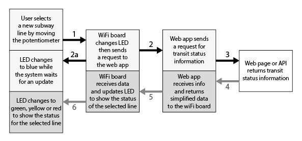
The tracker has two main parts:
- A Python web app
- Gets status information from a web page or API published by a transit authority
- Simplifes that information so it's easier to handle on a microcontroller
- Sparkfun's ESP8266 Thing Dev Board (plus some components)
- Lets you select which line you want to know about
- Requests status information from the Python app
- Updates the color of the light
This instructable is broken into three main sections:
- The Python web app (steps 4-5).
- The ESP8266 board (Sparkfun's getting started tutorial, and steps 6-9).
- Some suggestions for making it your own (steps 10-11)
What You Need to Know
You should have basic knowledge of Python, Arduino and electronics:
- Run Python code and install new modules
- Upload and run Arduino code
- Build simple electronic circuits
- Solder components to circuit boards
You should also be comfortable learning as you go and troubleshooting. Even though no single step is very complicated, different elements need to work together and you might run into problems without an obvious cause.
What You Need to Get
Software: You can test the Python app locally, but to deploy it online you'll need access to a server. The most beginner friendly option we found is PythonAnywhere, which requires a paid $5/month account. We've also linked to other options, many of which are free but have a higher learning curve.
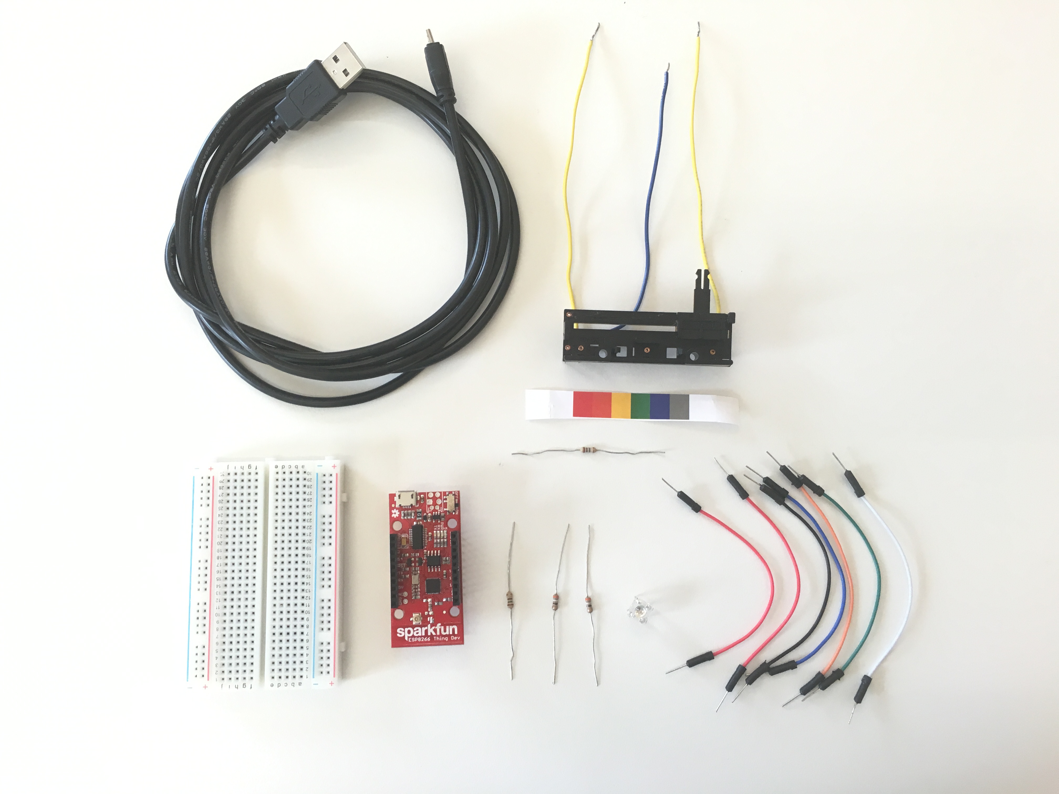
Hardware: Includes the Sparkfun ESP8266 Thing Dev Board and a handful of common hobbyist components. The total hardware cost is $40-50, plus tools such as a soldering iron and multimeter. We've included Sparkfun links to make it easier to buy everything together, but feel free to use what you have or to buy similar items elsewhere.
Hardware also varies depending on if you want to use a breadboard. Breadboarding lets you avoid permanent connections, but you'll need to solder headers to the ESP8266 board – which will affect the final form factor.
Enclosure: The only thing you absolutely need is a drawing or printout of colored squares to use as a scale for the potentiometer. Otherwise it depends what you decide to build.
Hardware list
- SparkFun ESP8266 Thing Dev Board
- Potentiometer, linear
- www.sparkfun.com/products/11621 $2.50
- Choose the potentiometer based on the final form factor you want - a slider, a dial, etc.
- www.sparkfun.com/products/11621 $2.50
- RGB LED, common anode
- Resistors (based on the components above)
- For red LED: ~80 ohms or a bit higher
- For green and blue LEDs: Two resistors at ~15 ohms or a bit higher
- For potentiometer: at least 23 kohms
- Resistor kit: www.sparkfun.com/products/10969 $7.95 (overkill but handy to have around; choose the next highest value for the LED resistors)
- Micro USB cable
- USB wall charger
If using a breadboard
- Breadboard
- Two 10-pin female headers
- www.sparkfun.com/products/11376 $1.00 for 2
- Jumper wires
If not using a breadboard
- Hookup stranded wire
- Small perf board (for RGB LED and resistors)
- [Very optional, see step 9] SPDT slide switch
- [Very optional, see step 9] Momentary switch
Tools and miscellaneous
- Soldering iron and solder
- Multimeter
- Wire cutters (if not using a breadboard)
PYTHON: Write a Web App

1. Install Flask
Flask is a simple framework for creating web apps. Install it with pip install Flask.
2. Run the web app
Download and run 'tracker.py'.
The program was written for Python 2.7 and uses xml, json, and urllib modules. These are part of the standard Python library, so you shouldn’t need to install them.
While the program is running, open your web browser to http://localhost:5000/nycstatus.html. You should see the name of each subway line followed by a comma, a status summary, and a newline (which may show up as a space, like in the image above).
Why a web app?
The subway tracker uses a color code to display the status of each subway line: good (green), possible problems (yellow), and definite problems (red).
To do this, you need information published by the transit authority. Different transit authorities use different formats and often include more information than you need. For example, the New York City MTA publishes status information in XML format at http://web.mta.info/status/serviceStatus.txt.
Because the ESP8266 has limited memory, it’s easier to use Python to process the text and then send simpler information to the ESP8266. This also makes it easier to adapt the Arduino code to different transit systems.
Troubleshooting tips
This code ran on Python 2.7 in June 2016. Check that all the libraries are installed, you have the right libraries for your version of Python, and you're using the right commands for the library.
Check that http://web.mta.info/status/serviceStatus.txt is live and hasn’t changed format. As of June 2016, this is an XML text file that uses the structure outlined in 'MTA-XML.txt'.
PYTHON: Deploy the App
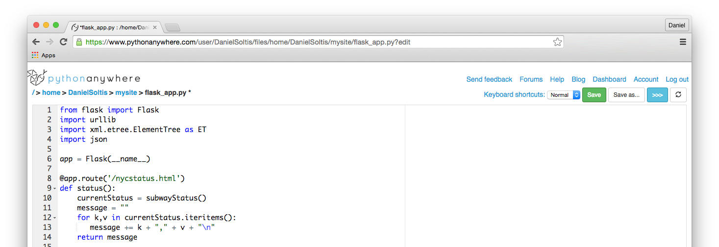
Once you've tested the code locally, you need to deploy it to a server.
Option 1: Host on pythonanywhere.com
PythonAnywhere is an easy-to-use online IDE and hosting service for Python. It supports Flask and deployment is straightforward, but you'll need a $5/month 'Hacker' account to enable your app to access most websites.
Once you create an account, follow the instructions for setting up a web app at https://www.pythonanywhere.com/task_helpers/start/...
A few key changes:
- When you are selecting which version of Python to use, select 2.7 instead of 3.4
- Feel free to finish the full tutorial, or you can stop once you get the step where you are editing the file flask_app.py. Replace the code with your code.
- Remove the final lines of the code: if __name__ == "__main__": app.run()
- Click "Save" and the reload button (a circle of two arrows at the top right)
Test by loading http://yourusernname.pythonanywhere.com/nycstatus.html
Option 2: Deploy elsewhere
There are several options for deploying a Flask app at http://flask.pocoo.org/docs/0.11/deploying/. Many are free but more complicated to set up.
Option 3: Use our server
If you don't want to or can't deploy the app to a server, feel free to point your Arduino code to danielsoltis.pythonanywhere.com. No promises, though.
ESP8266: Get Started
Now that the Python code is working, you can set up your hardware.
First, follow Sparkfun's tutorial for getting started with the ESP8266 and Arduino.
Troubleshooting note
If you run into problems uploading code to the board, you may need to connect pin 0 to ground.
The tutorial's comments have recommendations for fixing this in software.
You can also solve the problem physically. Unplug the board, connect pin 0 to ground, then plug the board back in. This starts the board in programming mode. If you turn the board off and then on again, you’ll need to disconnect pin 0 for the code to run.
ESP8266: Build Your Circuit
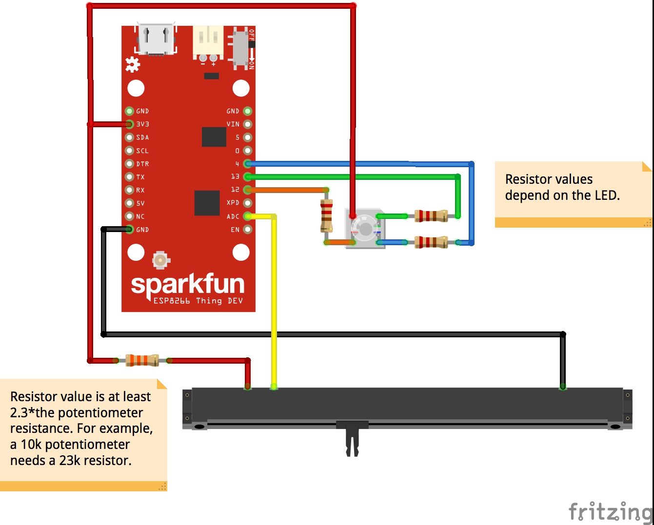

The photos show the electronics on a breadboard; you can also solder components directly to the ESP8266 board.
Potentiometer.
The board's analog-to-digital converter (ADC) only works up to 1V, so you need to add a fixed resistor between power and the potentiometer. The value of that resistor should be at least 2.3 times the resistance across the potentiometer. For example, for a 10k potentiometer you need at least a 23k resistor.
Connect the resistor to 3.3V and one end of the potentiometer. Connect the other end of the potentiometer to ground.
Then power up the board and measure the voltage across the potentiometer. It should be near but below 1V. If it is too high, try a higher value resistor. If it is too low (such as 0.5V), try a lower value resistor. Once the voltage across the potentiometer is below 1V, connect the wiper to the ADC.
RGB LED.
The LED shown in the schematic is a common anode LED. Connect the common leg to 3.3V, and then each color's leg in series to a resistor and a pin: connect red to pin 12, green to pin 13, and blue to pin 4.
ESP8266: Run Test Code and 'tune' the Potentiometer
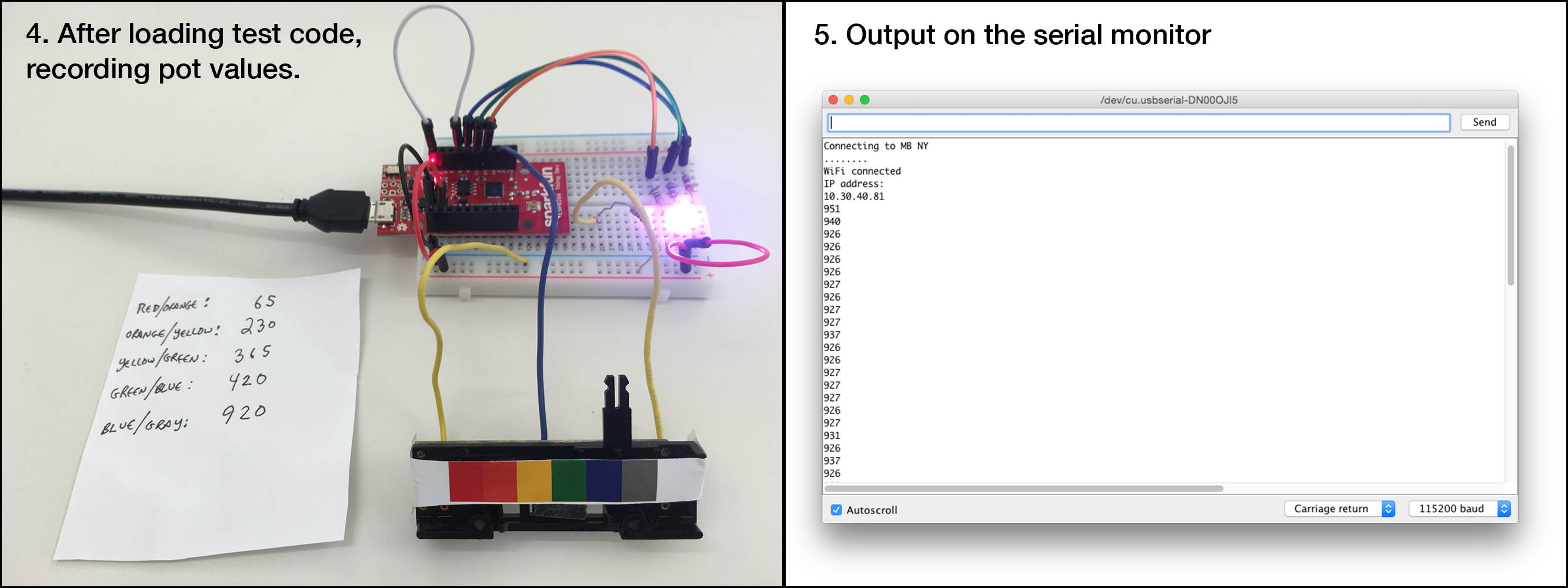
1. First, some arts and crafts
Decide which subway lines you want to be able to check. Draw or print a scale that is the width of the moveable area of your potentiometer and shows the color of each line, evenly spaced. (For example, 'colors.eps' shows six lines near our studio.) Then attach the scale to the potentiometer, so you can move the wiper to indicate a line.
2. Run the test code
Download 'subway_tracker_test.ino' and open in Arduino. Replace "YOUR WIFI" and "YOUR PASSWORD" with your wifi name and password, and upload it to the board. (Don't forget that to upload code, pin 0 needs to be grounded when you turn on the board.)
Open the serial monitor and set the speed to 115200.
First the board will attempt to connect to your wifi. This lets you see if the connection is working.
Then it will cycle the LED through red, green, blue and then white (all on). This lets you make sure the LED is connected and working correctly.
3. Tune the potentiometer
Finally, the serial monitor displays the value of the potentiometer. Move the wiper to the edges where each color meets the next color, and record the value of the potentiometer at each edge.
ESP8266: Customize and Run the Arduino Code
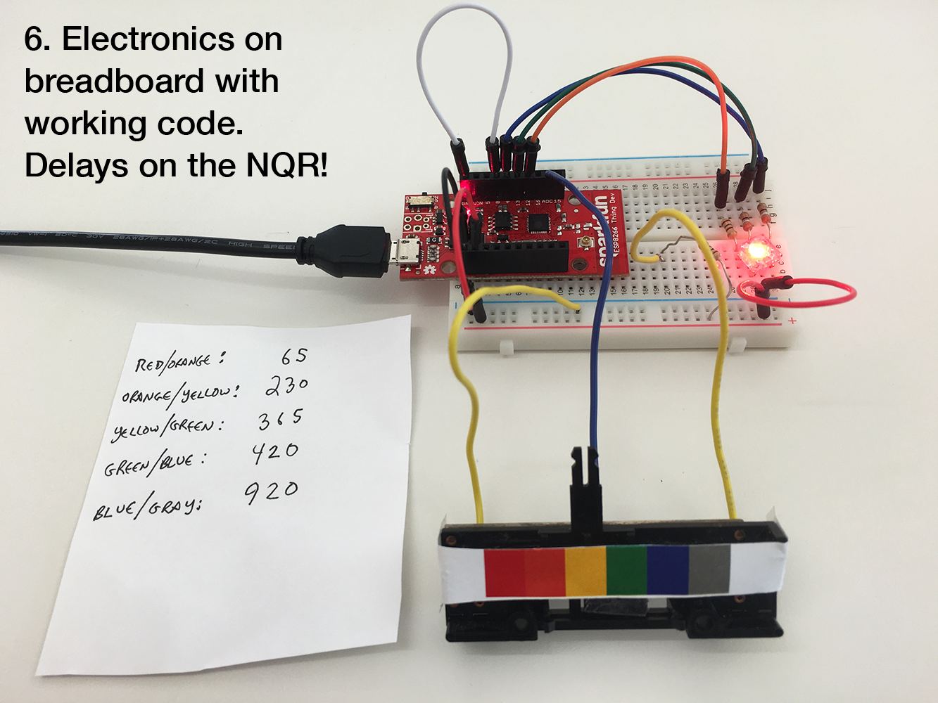
4. Download the real code
Download 'subway_tracker_nyc.ino' and open it in Arduino.
5. Customize variables
- Replace "YOUR WIFI" and "YOUR PASSWORD" with your wifi name and password.
- Replace "YOUR URL.COM" with the URL of the server that's hosting your Python code. If you're using PythonAnywhere, that's yourusername.pythonanywhere.com.
- Find the String variable lines[6]. Change the number to the number of lines you want to check. For each string in the array, write in the name of a line (as it appears when you run the Python app). Follow the order of the lines on your scale, with the line corresponding to the lowest potentiometer value first.
- Find the int variable cutoffs[5]. Change the number to one less than the number of lines you want to check. In order from lowest to highest, write in the values you recorded from the previous step.
6. Upload the code to your board
When the board first starts, the LED will turn blue. Once the board receives a status result, the LED will turn green, yellow or red.
When you move the potentiometer to a new line, the LED turns blue briefly while it checks for a new status, then displays the status for the selected line.
That's it!
Troubleshooting/bugs
If you leave the board on for a few days, it tends to freeze. A reboot fixes it, but more robust code would probably be a better solution.
Downloads
MAKE IT YOUR OWN: Build an Enclosure
Now you have working electronics, but bare boards are not durable and don't look like a lamp. So this is your opportunity to get creative.
For reference, the 3D files we used for our lantern enclosure are on Tinkercad (body and lantern), and we used tracing paper as a diffuser for the lantern panels.
From breadboard to enclosure
If you've been prototyping on a breadboard and want a permanent lamp, now is a good time to solder the components to the board.
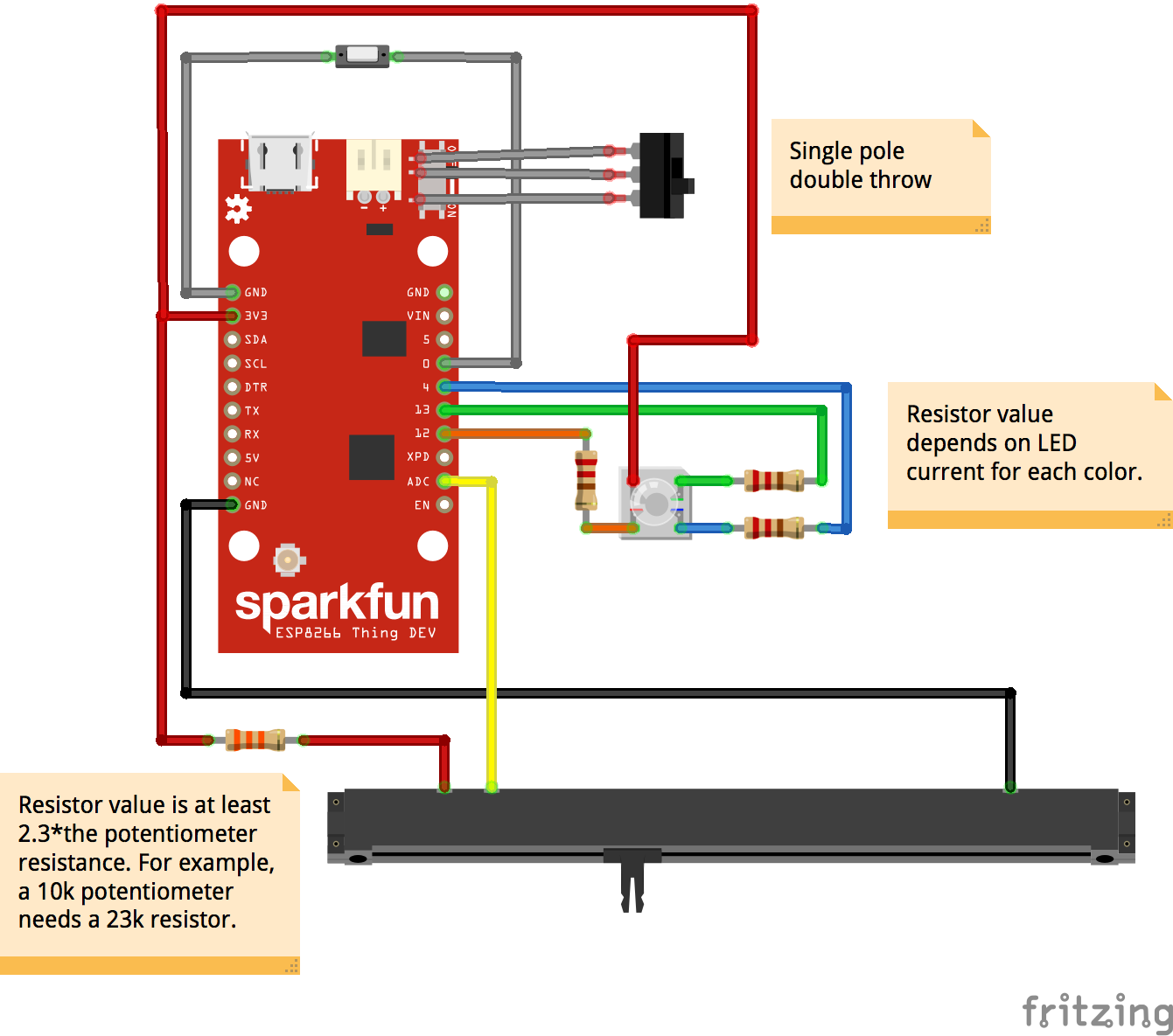
If you plan to enclose the board completely, you might want to add a couple of switches: one for connecting pin 0 to ground if you want to load new code, and one that gives you access to the boards' on/off switch (see the updated circuit diagram).
However, to solder an external switch to the on/off switch, you'll need to remove the existing switch and solder wires connecting to a new switch in its place. Clearly this starts to destroy your board, so only do it if you're confident in your soldering skills.
MAKE IT YOUR OWN: Customize to a Different Transportation System
London
The Python code requests status information for the NYC subway (at /nycstatus.html) and for the London Underground (at /lonstatus.html).
To make the London request work, register an app at https://api.tfl.gov.uk/ and enter your app id and key into the Python code. (Note that the TFL returns status information in JSON, so the code is a bit different.)
Then check /lonstatus.html on your server's URL. The result is in the same format as the NYC results, but the line names and status information are different. You'll need to change the URL variable to "lonstatus.html", update the line names in the lines[] variable, and update the strings for the good and delays variables.
The code is set up so that one status is good (green), one is bad (red), and everything else is in between (yellow). London reports more kinds of results (severe delays, minor delays, etc.), so you could consider how you want to map status to color.
Other transit systems
If you want to adapt the code to another location, you'll need to determine where and how to request the status information, what format that information is sent in, and how to convert that information into the simpler format the Python code returns.