Study Buddy: an Esp32 Tool

Study Buddy is a DIY IoT project that helps you stay focused and manage your study sessions effectively. It combines an ESP32 microcontroller with various sensors and outputs to create a smart study assistant. This device can indicate a "Do Not Disturb" status with an LED, track your study time while detecting if you're actually present, alert you if the environment gets too noisy, and even let you trigger a panic alarm sound if needed. All of these features are controlled and monitored via the Blynk mobile app, giving you remote control and feedback on your phone.
What does it do? In a nutshell, the Study Buddy provides the following features:
- Do Not Disturb Light: A visible LED that you can toggle on/off through the Blynk app to signal to others that you're focused and shouldn't be disturbed.
- Panic Alarm: A button in the app triggers a speaker to play a loud sound – think of it as an alert or panic button for immediate assistance or a quick "alarm" to break your session in emergencies.
- Smart Study Timer: You can set a study session duration in the Blynk app. The system will run a timer for your session and use an ultrasonic sensor to detect your presence. If you step away from your desk, the timer can pause (ensuring you only count actual study time) and send you a notification. When you return, it resumes and notifies you. At the end of the session, you'll be alerted that your focused study time is complete. The LED strip will display how much time you have left in binary.
- Presence Notifications: Whenever you leave your study space or come back (during an active session), you'll get a push notification via Blynk. This helps you keep track of unplanned breaks.
- Noise Level Warnings: A microphone monitors ambient noise. If the noise level in your environment gets too high (beyond a set threshold), the system sends a notification to your phone letting you know it's getting noisy – a reminder to eliminate distractions or move to a quieter spot.
Why is it useful? If you struggle with staying on track during study or work sessions, this project can be your companion. It essentially implements a smart Pomodoro-like timer with extra features: it not only times your session but also keeps you honest about actually being at your desk and alerts you to external distractions. The "Do Not Disturb" light can help communicate your focus mode to roommates or family without saying a word, and the noise monitor can alert you to put on noise-cancelling headphones or address the disturbance. The panic alarm is an extra touch for fun or urgent situations. Overall, the Study Buddy can improve your productivity by creating a more focused environment and structured study schedule.
In this tutorial, we'll walk through how to build this project step-by-step, in classic Instructables style. This includes gathering the necessary components, wiring them up to the ESP32, programming the device (with full code provided), setting up the Blynk app dashboard, assembling everything together, and testing the features. By the end, you'll have your very own Study Buddy device and know how each part works. Let's get started!
Supplies

Before diving into the build, make sure you have all the required components and tools. Here's a list of what you'll need for the Study Buddy project:
- ESP32 Dev Board: The “brain” of the project. An ESP32 development board will be used to read sensors, control outputs, and communicate with the Blynk app over Wi-Fi.
- Ultrasonic Sensor: For presence detection. This sensor uses ultrasonic sound waves to measure distance. We'll mount it such that it can detect if you're sitting at your desk (short distance reading) or you’ve left (distance increases).
- LED Strip (or RGB LED): For the binary status bar.
- Single LED Light: For the Do Not Disturb indicator.
- Speaker with Amplifier: For playing sounds. A small speaker coupled with a basic audio amplifier module is used to output the panic alarm sound. The amplifier is needed because the ESP32’s output isn’t powerful enough to drive a speaker directly.
- Microphone Sensor Module: To detect ambient noise levels.
- Power Supply: The ESP32 can be powered via USB (5V) or a battery. During development, a USB cable is handy for programming and powering.
- Miscellaneous Components:
- A breadboard or prototyping board to assemble the circuit (at least during prototyping).
- Jumper wires (Male-to-male and possibly male-to-female) for connections.
- Smartphone with Blynk App: You'll need the Blynk IoT app (available for iOS and Android) and an account to create the mobile dashboard for control and notifications.
- Computer with Arduino IDE (or similar): To program the ESP32. We'll provide the code which you can upload via the Arduino IDE. Make sure to install the ESP32 board support and necessary libraries (notably the Blynk library and optionally the Adafruit Neopixel library if using an addressable LED strip).
Setup and Wire ESP32


With the components in hand, it's time to wire them to the ESP32. Below is a description of each connection. Refer to the wiring diagram for a visual guide.
ESP32 Pinout Reference: The ESP32 has multiple GPIO pins. We'll choose pins that avoid conflicts (for example, avoid pins used for boot mode or ones not available on all boards). The exact pin numbers can be adjusted if needed, but be sure to update the code accordingly. Our suggested pin assignments are:
- Ultrasonic Sensor (HC-SR04):
- VCC: Connect to 5V on the ESP32 (the ESP32 DevKit has a 5V pin, which provides USB voltage). The sensor typically needs 5V for full range.
- GND: Connect to a GND pin on the ESP32.
- Trig Pin: Connect to an ESP32 digital output pin (e.g., GPIO 5). This pin will be used to send the trigger pulse.
- Echo Pin: Connect to an ESP32 digital input pin (e.g., GPIO 18). Important: The echo pin outputs a 5V logic signal. To avoid damaging the 3.3V ESP32 input, use a simple voltage divider or level shifter. For example, you can use a 1kΩ and 2kΩ resistor: connect Echo to a series 2kΩ, then from that point a 1kΩ to ground, and also that point goes to the ESP32 pin. This will bring the 5V down to ~3.3V. Alternatively, some have found the HC-SR04 works with 3.3V logic if VCC is 5V, but it's safer to level-shift.
- LED Strip (WS2812B NeoPixel) or Single LED:
- If using an addressable LED strip: Connect the strip's 5V (or VCC) to the ESP32 5V (or an external 5V source if using battery), GND to ESP32 GND, and the Data In of the strip to a digital output pin on the ESP32 (e.g., GPIO 15). Note: WS2812 LEDs run at 5V but typically accept 3.3V data signals for short strips. For reliability, you can use a level shifter on the data line (or even a simple 330Ω resistor in series plus a diode level shifter hack, if you are familiar). For a short strip or single LED, it's often fine without level shifting.
- If using a single LED as indicator: Connect the LED (with a resistor ~220Ω in series) to an ESP32 GPIO (e.g., GPIO 15) and to ground. For example, LED anode to GPIO through the resistor, LED cathode to GND. That GPIO will be configured as an output to drive the LED (HIGH to turn on if anode is connected, or LOW to turn on if you connect cathode to pin and anode to 3.3V through resistor, depending on configuration).
- Speaker and Amplifier:
- Connect the audio input of your amplifier module to one of the ESP32’s DAC pins. The ESP32 has two DAC (digital-to-analog converter) pins which can output analog voltages: GPIO25 (DAC1) and GPIO26 (DAC2). We'll use, for example, GPIO 25 to output the sound signal.
- Connect the amplifier’s power: VCC to 5V (for a PAM8403, 5V is needed; some small amps might run at 3.7-5V which is fine with a Li-ion battery or USB 5V), and GND to ESP32 GND.
- Connect the speaker to the amplifier’s output terminals (usually labeled SP+ and SP-). If using a mono amplifier like PAM8403, you'll use the L+ and L- (or R+ and R- for the right channel, either one channel is fine).
- Ensure common ground between the ESP32 and amplifier (already done by connecting grounds together).
- Microphone Module:
- Connect the VCC of the microphone board to 3.3V on the ESP32 (most analog mic modules and breakouts can run on 3.3V; check your module’s spec. If it specifically needs 5V, use 5V, but analog output should still be within 0-5V so might need scaling; many modules have output that doesn’t swing full 0-5 though).
- Connect GND of the mic to ESP32 GND.
- Connect the analog output of the microphone to an ESP32 analog input pin. For example, use GPIO 34 (which is an ADC1 channel on the ESP32). Note that pins GPIO34-39 are input-only and work well for analog input. We choose GPIO34 for the mic input.
- If your microphone board also has a digital output (some do, labeled D0 or similar, with a comparator for simple HIGH/LOW on threshold), you can leave it unconnected or use it for a simple binary noise trigger. In our project, we’ll use the analog output for more flexibility.
- Power and Ground:
- Connect a common GND line that ties the ESP32, ultrasonic sensor, mic, LED strip, and amplifier all together.
- Depending on your power source: if using USB, the ESP32 5V pin will be powered from USB 5V. Use that for the sensor and possibly amplifier. The 3.3V pin on ESP32 is the output of its regulator, good for low-power sensors like the mic module.
- If using battery, ensure the 5V devices (sensor, amp, LED strip) are getting appropriate voltage via a boost converter or use components that can run at the battery voltage (for example, some addressable LEDs can run at 3.7V with lower brightness, some amps can run at 3.7V with reduced output, and the sensor might run at 3.3V but with reduced range).
- It's recommended to build the circuit on a breadboard first to test everything. Keep wires tidy to avoid confusion.
Code

Now that the hardware is set up, let's get into the code. We will use the Arduino IDE for programming the ESP32. Make sure you have added the ESP32 board support to the Arduino IDE and installed the required libraries:
- Blynk library: This will enable the ESP32 to connect to the Blynk app and communicate with the widgets (buttons, labels, etc.) we will set up.
- Adafruit NeoPixel library: Only needed if you are using an addressable LED strip for the DND light. This library makes it easy to control the color of WS2812B LEDs. (If you're using a simple LED, you don't need this library.)
- The ESP32's built-in functions will handle the ultrasonic sensor (with pulseIn()), and analog readings for the mic.
What does the code do?
The code will handle the following tasks:
- Connect to your Wi-Fi and the Blynk cloud server using your unique authentication token (which you will get from the Blynk app).
- Read the ultrasonic sensor periodically to check if the user is present at the desk.
- Read the microphone's analog value periodically to gauge noise levels.
- Control the DND light (LED/strip) based on a virtual button in the app.
- Play a sound on the speaker when the panic button is pressed in the app.
- Manage a study session timer:
- It starts when you activate focus mode (DND) and have set a session duration.
- It counts down only when you are present (pausing when you're away).
- It sends notifications on leave/return events and when the session is completed.
- It updates a label in the app with the remaining time.
- Send a notification if noise goes above a set threshold while in DND mode.
- Update the Blynk label widgets for status (time left, noise level, etc.).
We'll use Blynk's virtual pins to communicate between hardware and app:
- Virtual pin V0: "Do Not Disturb" toggle button.
- Virtual pin V1: "Panic" button.
- Virtual pin V2: "Session Timer Setter" (for example, a slider to select study session duration in minutes).
- Virtual pin V3: "Session Status/Time Display" (label widget to show remaining time or status).
- Virtual pin V4: "Noise Level Display" (label widget to show current noise reading or state).
The code is attached below.
Let's go through the code step by step. You can find the complete code below, which you can copy into the Arduino IDE. Be sure to replace the placeholders for WiFi credentials and Blynk auth token with your actual SSID, WiFi password, and the token from your Blynk project email.*
Code Summary:
Let's briefly summarize how the code works:
- We start by including libraries and defining pins as constants. The USE_NEOPIXEL directive (which you can define at the top if you have a NeoPixel strip) allows the code to optionally use the Adafruit_NeoPixel library. If you're using a simple LED, you can ignore or remove the NeoPixel parts.
- WiFi and Blynk credentials need to be filled in with your network and Blynk project info.
- In setup(), we initialize the hardware (pin modes, etc.), connect to WiFi, and start Blynk. We also initialize two recurring tasks using timer.setInterval: one to read sensors (sensorCheck) every second, and one to update the countdown timer (updateTimer) every second.
- Ultrasonic reading (measureDistanceCM): This function triggers the HC-SR04 and reads the echo pulse using pulseIn. It calculates distance in cm using the formula distance = (duration * speed_of_sound) / 2. We use speed_of_sound ~ 0.0343 cm/µs. A timeout of 30ms is set for pulseIn to avoid long waits if no object is detected (30ms roughly corresponds to 5m distance, beyond the sensor’s reliable range).
- sensorCheck(): This is called every second. It checks the ultrasonic sensor to update isPresent (whether you're at your desk). If a study session is running (sessionRunning == true), it will send a Blynk notification when it detects you leaving or returning, using Blynk.notify(). It also reads the microphone analog value, converts it to a percentage (0-100) for simplicity, and if DND mode is active, will send a notification if the noise crosses the threshold (e.g., someone starts vacuuming or loud music plays). The threshold (set as 70% in code) can be tuned to your environment. The noise level (in percent) is then sent to the Blynk app on virtual pin V4 so that one of our label widgets can display it.
- updateTimer(): This runs every second to handle the countdown logic. If a session is running, and you are present, it decrements the remaining time. If you are away (isPresent == false), the time does not tick down – effectively pausing the timer. It then formats the remaining time into mm:ss and writes it to virtual pin V3 for display on the app.
- BLYNK_WRITE(V0) - DND button: When you toggle the "Do Not Disturb" button in the app, this function executes. If the button is turned on, the code enables DND mode: lights up the LED/strip, and if a session duration has been set (via V2), it starts the session timer (initializing the timeRemaining and setting sessionRunning = true). It also sends a notification that the focus session started. If the DND button is turned off, the code turns off the LED and, if a session was running, stops it (and notifies that it ended early). The dndActive flag tracks the state of focus mode.
- BLYNK_WRITE(V1) - Panic button: When the panic button is pressed in the app, we call playPanicAlarm(). The playPanicAlarm function generates a 1 kHz tone for 1 second on the DAC pin connected to the speaker. This is a simple implementation using dacWrite in a loop to create a square wave. (In a more advanced setup, you could play an actual sound file or a siren effect.)
- BLYNK_WRITE(V2) - Session time input: Whenever you adjust the slider (or whatever widget is used) for the session duration, this function updates sessionDurationMin. We don't start the timer immediately here; instead, it will take effect when you activate DND. This allows you to set the desired minutes and then hit the DND button to begin.
- Other code bits: We use BlynkTimer (which is essentially the SimpleTimer) to avoid using delays in the main logic (except in the sound generation where a short delay is acceptable). This keeps the Blynk connection responsive. We also use Blynk.notify() for push notifications. (If using the new Blynk IoT platform, you might use Blynk.logEvent tied to events set up in the Blynk console for richer notifications.)
After writing the code, upload it to your ESP32 using the Arduino IDE. Open the Serial Monitor at 115200 baud to see debug prints (we call Serial.begin in setup) if you want to monitor what's happening (like distance measurements, etc., you can add Serial prints for debugging if needed).
Note: Make sure to modify the code for any pin changes or if you chose to use a different approach (e.g., if you use a different LED pin or if you decide not to use the NeoPixel library, remove that part). Also, adjust the noiseThreshold or the distance < 100 logic based on real-world testing (for example, depending on where you place the ultrasonic sensor, you might find a different distance works better to detect presence versus absence).
Blynk Configuration


With the hardware and firmware ready, the final piece is setting up the Blynk app interface. Blynk will allow us to control the ESP32's features and get feedback (like notifications and sensor readings) on our phone. If you haven't used Blynk before, you'll need to:
- Download the Blynk IoT app from the App Store or Google Play Store.
- Create a Blynk account (or log in if you have one).
- Create a new project in the app. Give it a name like "Study Buddy", and select the device type as ESP32 (and connection type WiFi). Blynk will generate an Auth Token for the project – copy this token because you'll need to paste it into the code (we put a placeholder "YOUR_BLYNK_AUTH_TOKEN" in the code which should be replaced with this actual token).
- In the project dashboard (in edit mode), add the following widgets to set up the interface:
- Button Widget (Virtual V0) – Label it "Do Not Disturb" or "Focus Mode". Set this button to Switch mode (so it toggles on/off). Assign it to V0. This will be the toggle for DND light and to start/stop a focus session.
- Button Widget (Virtual V1) – Label it "Panic Alarm". Set this one to Push mode (momentary). Assign to V1. This triggers the alarm sound. (In push mode, it will send value 1 when pressed, and 0 when released; our code only cares about the 1 on press to start the sound.)
- Slider (Virtual V2) – Label it "Session Duration (min)". This will let you set the study session length in minutes. In the slider settings, set a range that makes sense – for example, 5 to 120 minutes (2 hours) or whatever fits your use case. Assign it to V2. (Alternatively, you could use a Step widget or a Numeric Input widget to input minutes more precisely. A slider is simple and intuitive, though.)
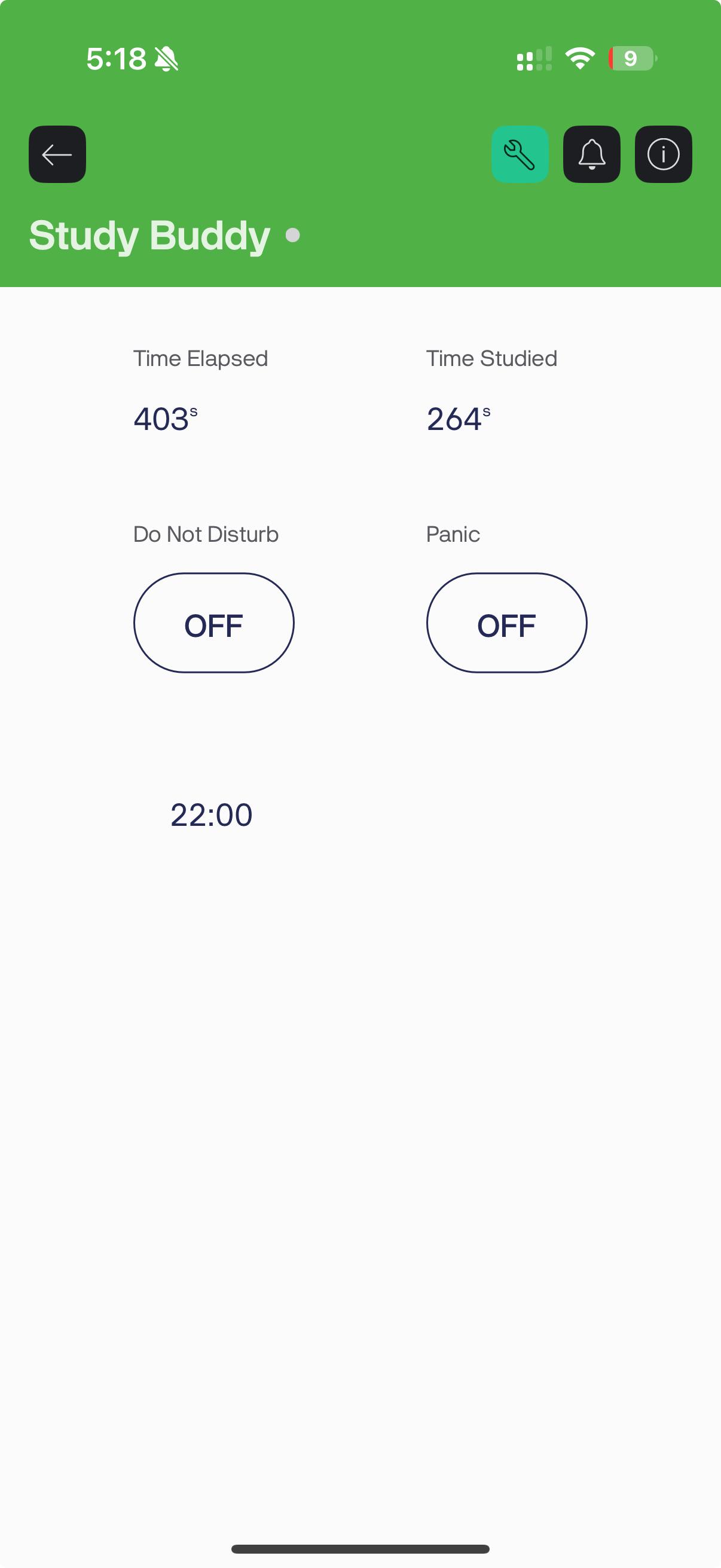
- Label (Value Display) Widget (Virtual V3) – Label it "Timer" or "Session Time Left". Assign to V3. This will display the remaining time on the countdown in minutes and seconds, updating every second via our code. In the settings for this widget, you can choose to display the raw value or add a label. For example, you might set it to display a concatenated string or simply rely on our code to send a formatted string. (If it expects a numeric value, it might just show "mm:ss" text as sent. Ensure the datatype is set to "String" or just use a Labeled Display which can show any text.)
- Label (Value Display) Widget (Virtual V4) – Label it "Noise Level". Assign to V4. This will show the current ambient noise as a percentage (0-100) or you can interpret it qualitatively. For example, you could set the label in the widget to "Noise: " and when our code does Blynk.virtualWrite(V4, noiseLevel), it will display like "Noise: 42" (if 42%). You might also set a suffix "%" in the widget settings so it shows like "Noise: 42%". This way, you can glance at the app to see noise level. (This is optional for functionality; the main alert for noise is the notification when it's too loud. But having the reading can help you adjust the threshold or just be informative.)
- (Note: In Blynk, "Label" or "Value Display" widgets both essentially show text from the device. In the newer Blynk IoT app, you might have a "Labeled Value" widget where you set Label and it shows the value from a data stream. Just ensure V3 and V4 are allocated as datastreams if needed in the template. For simplicity in this tutorial, the concept is the same regardless of Blynk version – use virtual pins to send data to display widgets.)
- Notifications: Blynk by default will send notifications triggered by Blynk.notify() in the code to your phone as long as the app is running (you don't have to keep it open, but you need to be logged in and allowed notifications). On the new Blynk, you might need to enable the Notifications tile in the app and possibly set up events. We used Blynk.notify() for simplicity which works well in the legacy version. In Blynk IoT (new), the equivalent approach is to set up Events in the web dashboard and use Blynk.logEvent("event_code", "message"). In the code above, we included Blynk.logEvent("status", "...") as a comment – that would correspond to an event named "status" defined in the Blynk template for those who use Blynk IoT. If you stick to legacy Blynk, Blynk.notify will work out of the box for push notifications.
- After adding the widgets, link the Auth Token: either scan the QR code or copy the Auth Token from the project settings and ensure it's in your code (in the auth[] variable). Then upload the code to the ESP32.
- Power on the ESP32 (if not already) and ensure it connects to WiFi (you should see it come online in the Blynk app, indicated by a tiny dot or some status). In the serial monitor, you might also see debug info that it's connected.
- Now arrange the widgets nicely in the app interface. For example, you might have the DND button and Panic button side by side, the slider for time below them, and the labels for timer and noise below that. You can also use two LED widgets in the app (virtual LEDs) if you want to reflect status like presence or DND, but since we have physical indication and notifications, it's optional.
Blynk Datastream Summary (for clarity):
- V0 – Button: Do Not Disturb (Switch mode)
- V1 – Button: Panic Alarm (Push mode)
- V2 – Slider: Session Duration in minutes (5-120 range)
- V3 – Labeled Value: Session Timer (display mm:ss)
- V4 – Labeled Value: Noise Level (display 0-100%)
Double-check that the virtual pin numbers in the app match those in the code. If you changed any pins or decided to add more features (for example, a display for presence status), set them up accordingly.
Final Assembly

With everything working on the breadboard, you can assemble the project in a more permanent and user-friendly way. Here are some tips for final assembly:
- Mounting the Ultrasonic Sensor: This sensor will work best if it faces the area where you expect the user to be. Make sure the area in front of the sensor is clear of other obstructions that might give false readings.
- Placement of the Microphone: The mic should be placed such that it can pick up room ambient noise. If possible, position it away from the speaker to avoid the speaker's sound feeding directly into the mic (which could trigger the noise alert when the alarm plays!).
- LED Strip: Put in a visible place so that you can see how much time you have left.
- DND Light: Put in a place where others can see the light.
- ESP32 and Electronics: Consider using a small enclosure or a project box to hold the ESP32 board, the amplifier, etc. You can cut openings for the USB (for power/programming), for the sensor connectors, mic, speaker, etc.
- Speaker: Put it somewhere where the user will be able to hear it.
- Power Considerations: If you want the device to be semi-portable or at least not tethered to a computer, you can power it with:
- A USB wall adapter (like a phone charger) via the ESP32's USB port.
- A power bank or rechargeable battery pack (5V output to USB).
- A battery connected to the ESP32's Vin
Once everything is housed and placed, do a final check that all components are still functioning (sometimes a wire can slip out during assembly, especially from breadboard to final soldering).
Testing and Features in Action
Now for the fun part – testing out all the features of your Study Buddy to ensure everything works as intended. We will go through each feature one by one: Attached is a video demo of the project.
- Connecting to Blynk: Power up the device (if you haven't already). Open the Blynk app, and you should see your device status as online. If it's offline, recheck WiFi credentials and whether the ESP32 connected properly (look at the serial monitor or add an LED to indicate connection, if needed). Once online, you're ready to interact.
- Panic Alarm Button: In the app, press (and hold, if it's push mode) the Panic button (V1). The speaker should immediately play the alarm tone – a loud beep for one second (or as long as you hold if you modify the code differently). This sound should be quite audible. This tests the speaker and amplifier wiring. Release the button and it should stop (in our code, we play a fixed 1s tone on press, so it will stop after 1 second automatically).
- If the sound is too low or distorted, check the amplifier power or volume (if it has a potentiometer). If using a buzzer instead of speaker, you might hear a tone as well. Adjust the alarm frequency or duration in code if needed.
- If you want a continuous alarm as long as button is pressed, you could adjust code to start on press and stop on release, but our simple approach is just a short beep per press.
- Study Session Timer and Presence Detection: Set a session duration using the slider (V2). For testing, you might choose a short time like 1 or 2 minutes so you don't have to wait too long.
- The Timer label (V3) should show the starting time (e.g., "02:00" for 2 minutes) and count down.
- Now simulate leaving your desk: simply move out of the ultrasonic sensor's range (e.g., stand up and walk a few steps away). After about a second or two, the device should detect no presence. You should receive a push notification on your phone: "You left your study space. Timer paused." Also, if you watch the Timer on the app, it should stop decrementing when you're away (since we paused countdown when not present).
- While away, maybe the Timer label keeps showing the last time or might indicate paused (we did not explicitly show "paused" text, but the time will just not change).
- Now return to your desk (come back in front of the sensor). Within a second or so, you should get another notification: "Welcome back! Resuming your study session." And the Timer should resume counting down from where it left off.
- This verifies the ultrasonic sensor is correctly sensing presence/absence and the logic for pausing is working. If you didn't get the notifications, ensure notifications are enabled and the Blynk.notify calls are executing (check serial or logs).
- Let the timer run down to 0 by remaining present (or if you're impatient, you can temporarily set a very short duration or decrement the timeLeft manually in code for testing).
- Congratulations, you completed a full cycle with presence-aware timing!
- Noise Level Detection: Finally, test the noise alert feature. While a session is active (DND on), try creating a sustained loud noise or have some background noise:
- For example, play music on another device, or clap repeatedly, or have someone talk loudly. The microphone reading (noise level) in the app should spike near or above the threshold (which we set as 70% in code).
- If the noise remains high for a couple of sensor check cycles, the code will send a notification "Noise is too loud! 📢". You should see that on your phone. (We used an emoji just for fun.)
- Once things quiet down, the code won't notify again unless it goes loud again. If you want to test multiple times, you can make it quiet (drop below threshold for a moment) and then loud again to trigger another alert.
- If you're not getting a noise alert, you might need to adjust the threshold or ensure your microphone analog output is wired correctly. You can also check the raw analog reading via Serial to gauge values. Some sensors might output smaller range of values, so mapping 0-4095 may not reflect actual. Adjust the noiseThreshold percentage accordingly (for instance, if your mic values rarely go above 500 out of 4095, then our mapping yields low percentages – in such a case, you could either amplify the reading or set a much lower threshold percentage).
- Once it works, you'll have confidence that during your quiet study session, if a sudden noise occurs, you'll be alerted.
- General Monitoring: Even when you're not in a session (DND off), our code still updates the noise level display periodically. The presence notifications, however, are only active during a session in our logic. You could modify to always notify if needed, but it might not be necessary. The LED is also only active during DND. Feel free to test toggling DND without setting a timer (it should just act as a manual DND light with no timer).
- Power loss/restart: Try resetting or power cycling the device to ensure it reconnects to WiFi/Blynk automatically. The system should recover gracefully. If a session was in progress and you reset, obviously it loses track – you would start a new session as needed. The device isn't really meant to run while you're away for long (except maybe monitoring noise), so this is fine.
Throughout testing, keep an eye on the Blynk app and the physical indicators (LED, sound). If something doesn't work as expected, revisit the code and wiring. Common issues might be incorrect virtual pin assignment, or missing Blynk.run() causing app to not update, or sensor orientation issues for ultrasonic.
Example scenario in practice:
Imagine you're about to start a 30-minute study session. You open the app, and set 30 on the slider.The Study Buddy lights up the LED strip. You dive into work. Ten minutes in, someone in the next room starts playing loud music; your phone buzzes and the notification says "Noise is too loud! 📢". You realize the distraction and put on headphones to block it out (problem solved!). At 15 minutes, you absentmindedly get up to grab a snack – as soon as you leave, your phone pings "You left your study space. Timer paused." Oops! You quickly return, and you're greeted with "Welcome back! Resuming your study session." The timer had paused at 15:00 remaining and continues counting down.
Potential Improvements
The current version of Study Buddy is fully functional, but there are many ways you could expand or refine the project. Here are some ideas and potential improvements:
- Refine Presence Detection: The ultrasonic sensor works for basic presence/absence, but it could sometimes be triggered by something else (like someone passing in front of it). You could add a PIR motion sensor or a pressure sensor in your chair for more reliable detection of sitting. Even a computer vision solution (camera with ESP32-CAM or OpenCV on a PC) could detect if you're at your desk or looking at the screen.
- Better Sound Alerts: We used a simple tone for the alarm and session end. You could use the ESP32's ability to play WAV files (since it has DAC and ample memory or by using an SD card) to play a nicer alarm sound or a chime. Alternatively, integrate a buzzer for a simpler approach, or even use text-to-speech or recorded voice prompts ("Session Complete!", etc.).
- Ambient Lighting or Conditions: The Study Buddy could also monitor room temperature or lighting and help adjust your environment. For example, add a temperature/humidity sensor or a light sensor and then use the LED strip to signal if the room is too dark or too warm for studying.
- Pomodoro Cycle Support: Extend the functionality to support break timers. For example, after a study session, automatically start a short break timer (5 minutes) and then alert when break is over. The Blynk interface could have another button to switch between "Study" and "Break" modes or simply handle it in code with another set of durations (like a long press of DND could start a break countdown, etc.).
- Data Logging: Keep track of your study sessions over time. You could use Blynk or another service to log each session's actual focus time and breaks. Over weeks, you can analyze your study habits. Blynk's cloud (or using things like Google Sheets via an API or IFTTT) could record timestamps when you start and stop sessions or when you get distracted.
- Voice Assistant Integration: For a high-tech twist, integrate with a voice assistant or have the device speak. For example, using an ESP32 library for speech synthesis or sending events to Alexa/Google Assistant to set Do Not Disturb mode on other devices, etc.
- Multiple Users or Remote Monitoring: If you want, you could allow a parent or study partner to get notifications too, basically sharing the Blynk project or sending notifications to another device. This could be accountability feature.
- Improved Noise Detection: The noise sensor here is basic. You could implement an FFT on the ESP32 to detect specific types of noise or measure decibels more accurately. The ESP32 is capable of listening to I2S digital microphones which can give better audio analysis. For our purpose, the simple threshold works, but audiophiles could make a mini decibel meter out of it.
- Battery Optimization: If running on battery, consider using the ESP32's deep sleep modes to save power when idle. For instance, if DND is off (no active session), the device could sleep and wake periodically to check noise or wait for a command. This can be complex with Blynk (since you need to maintain connection), but maybe use BLE or other tricks.
- Enclosure and Aesthetics: Make a nice case for it. Perhaps laser-cut a custom "Study Buddy" case or 3D print a design that holds the sensor like a little robot on your desk. A clean setup will make you more likely to use it regularly.
- Alternate Applications: Realize that this setup could be repurposed. For example, it could serve as a basic security system (ultrasonic detects someone in room when shouldn't, noise detects intrusion, alarm can sound, LED can flash). By adjusting the logic or adding a few IF conditions, your Study Buddy can moonlight as a room alarm when you’re away.
- Using New Blynk Features: If you're on Blynk IoT (2.0), you could take advantage of Automation to e.g. automatically toggle DND light at certain times or integrate with other smart devices. Also, Blynk allows you to create a web dashboard, so you could monitor your study session from a computer as well, or trigger the panic alarm from a webpage.
- Social Sharing: Maybe add a feature to tweet or post when you start/finish a study session to share with friends for motivation. This could be done by integrating an API like IFTTT or using webhooks from Blynk events.
Feel free to modify and build upon this project to suit your needs. The Study Buddy is a platform to experiment with IoT in a practical scenario – improving productivity. We hope this tutorial was helpful and inspires you to create your own smart gadgets for a better study or work routine. Happy building and happy studying!