Strider Camera Robot V6
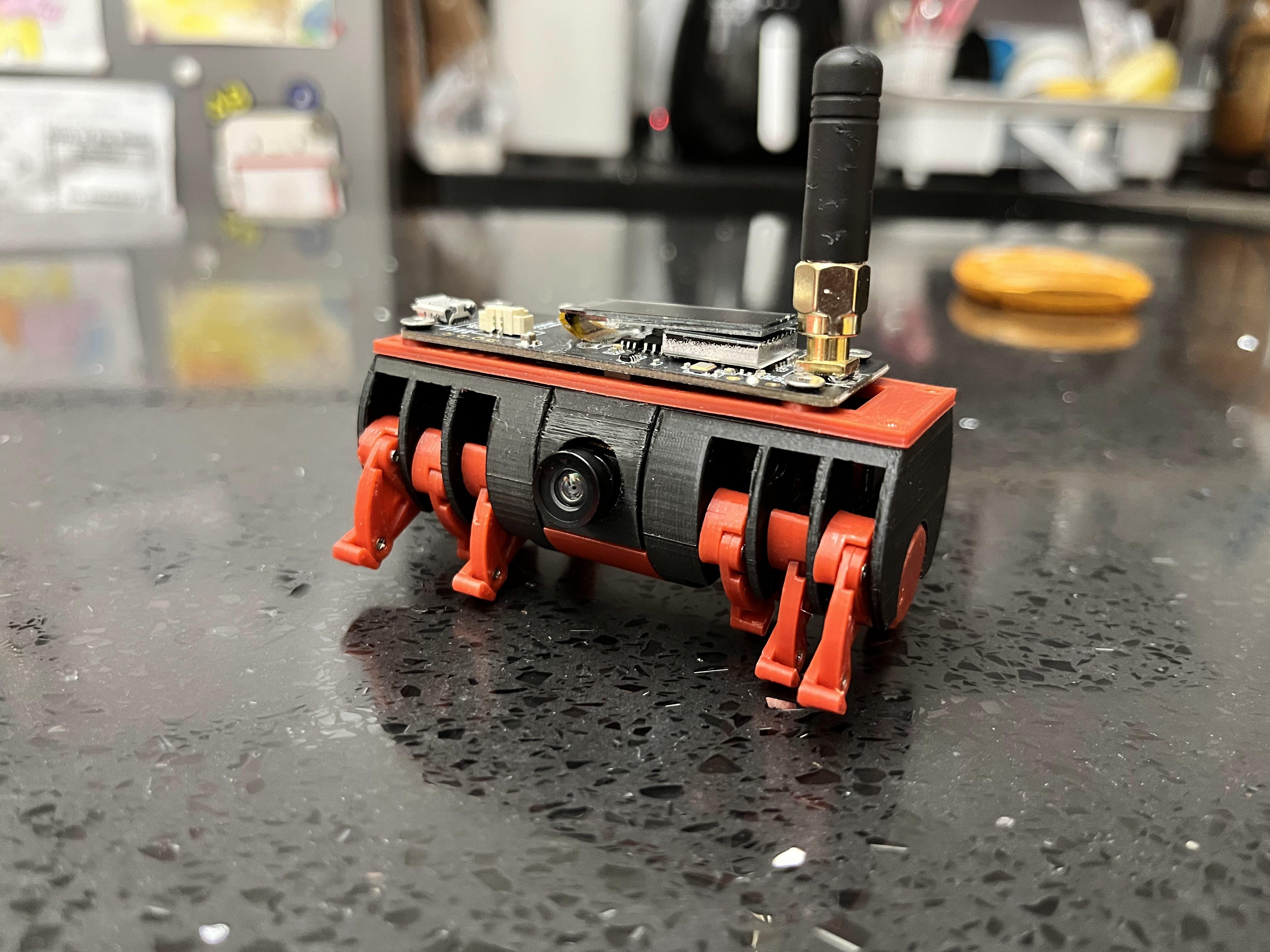
This Instructables show how to build Strider Walker V6.
Supplies
- TTGO T-Journal ESP32 Dev Board
- OV2640 or OV3660 camera module with a little bit longer FPC
- Two 4.3g servo with 360 degree rotation option
- Two 801525 Lipo batteries
- Two Paperclips
- SMA Coaxial PCB mount Jack
- A short SMA Antenna
- Around 60-100 pieces of 4mm (actually 3.6mm) M1.2 screws
Paperclip Axis
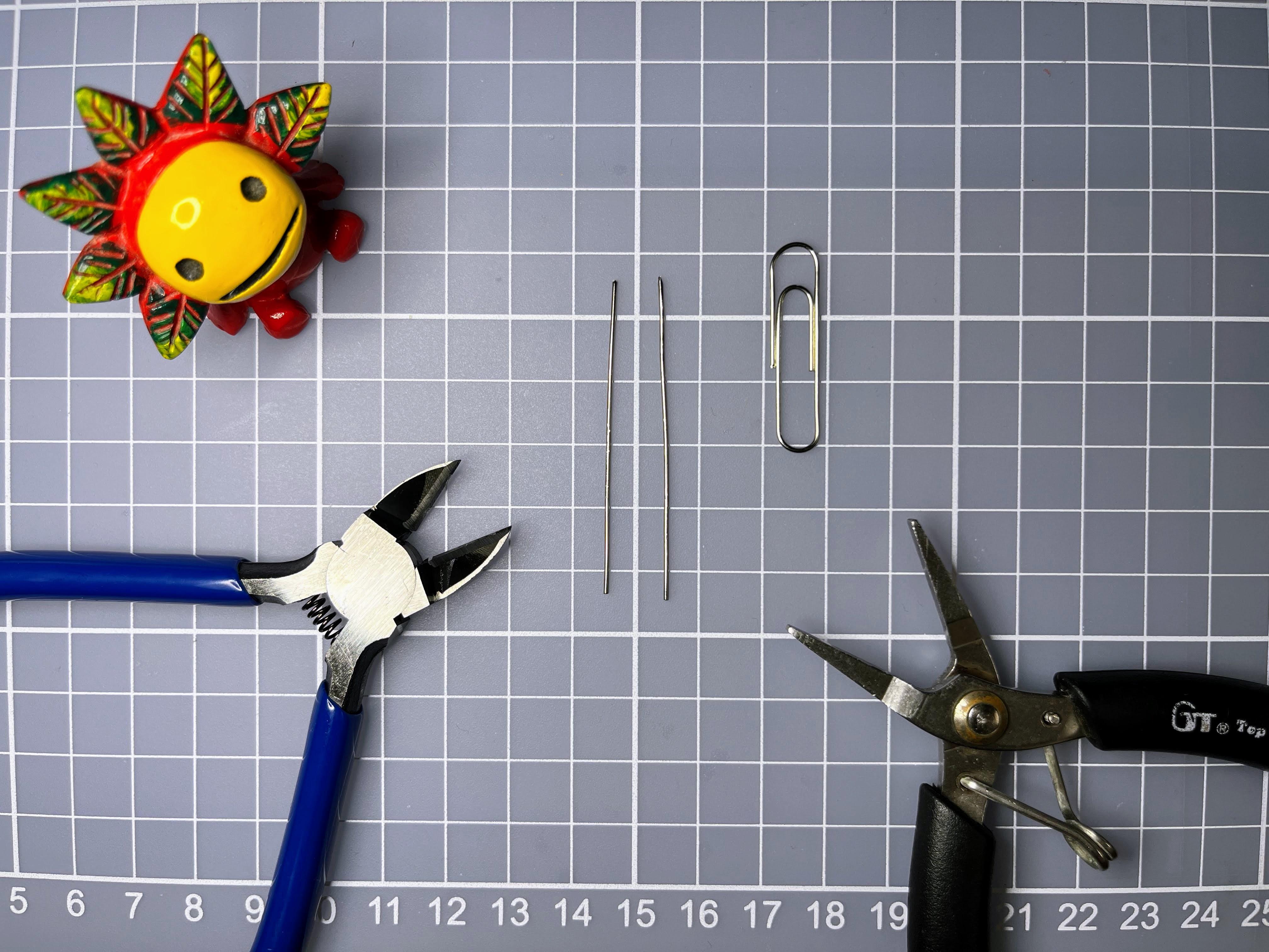
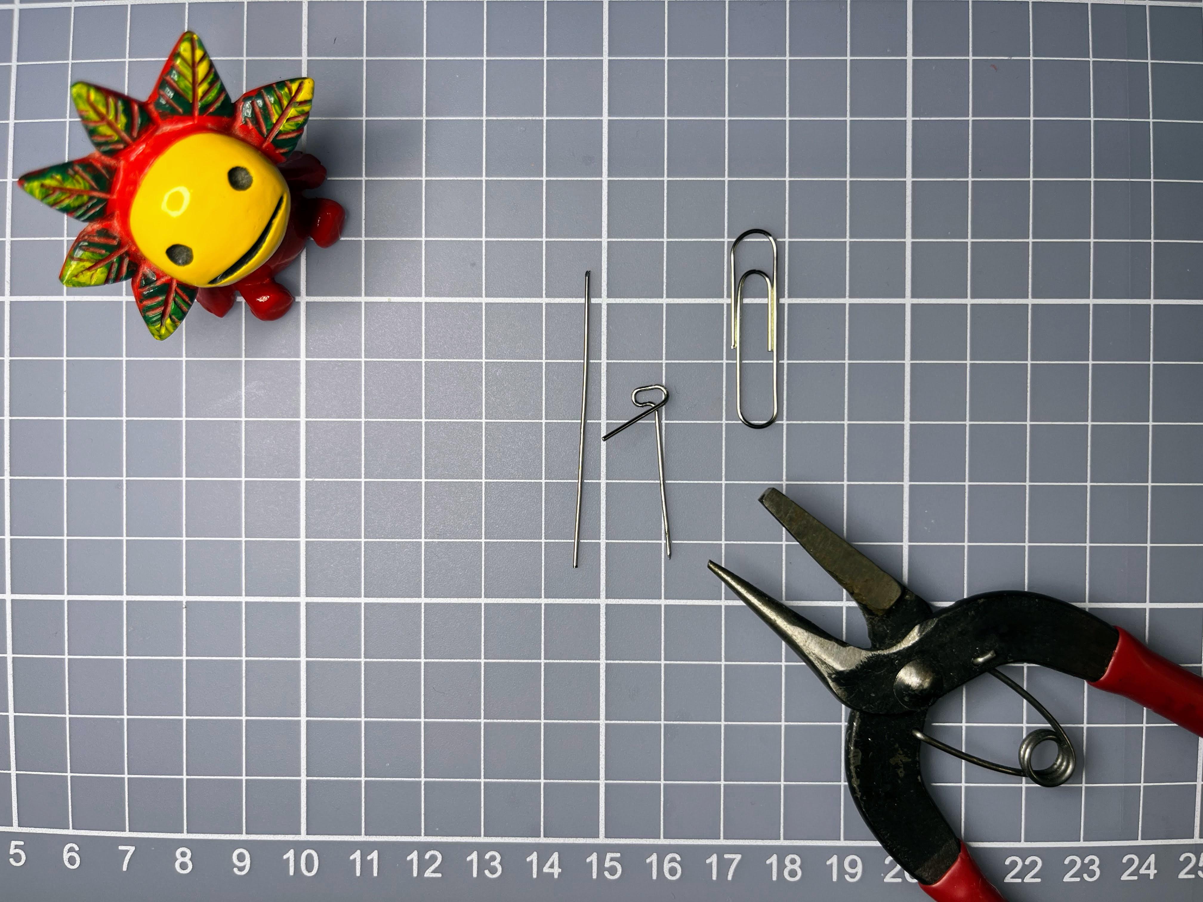
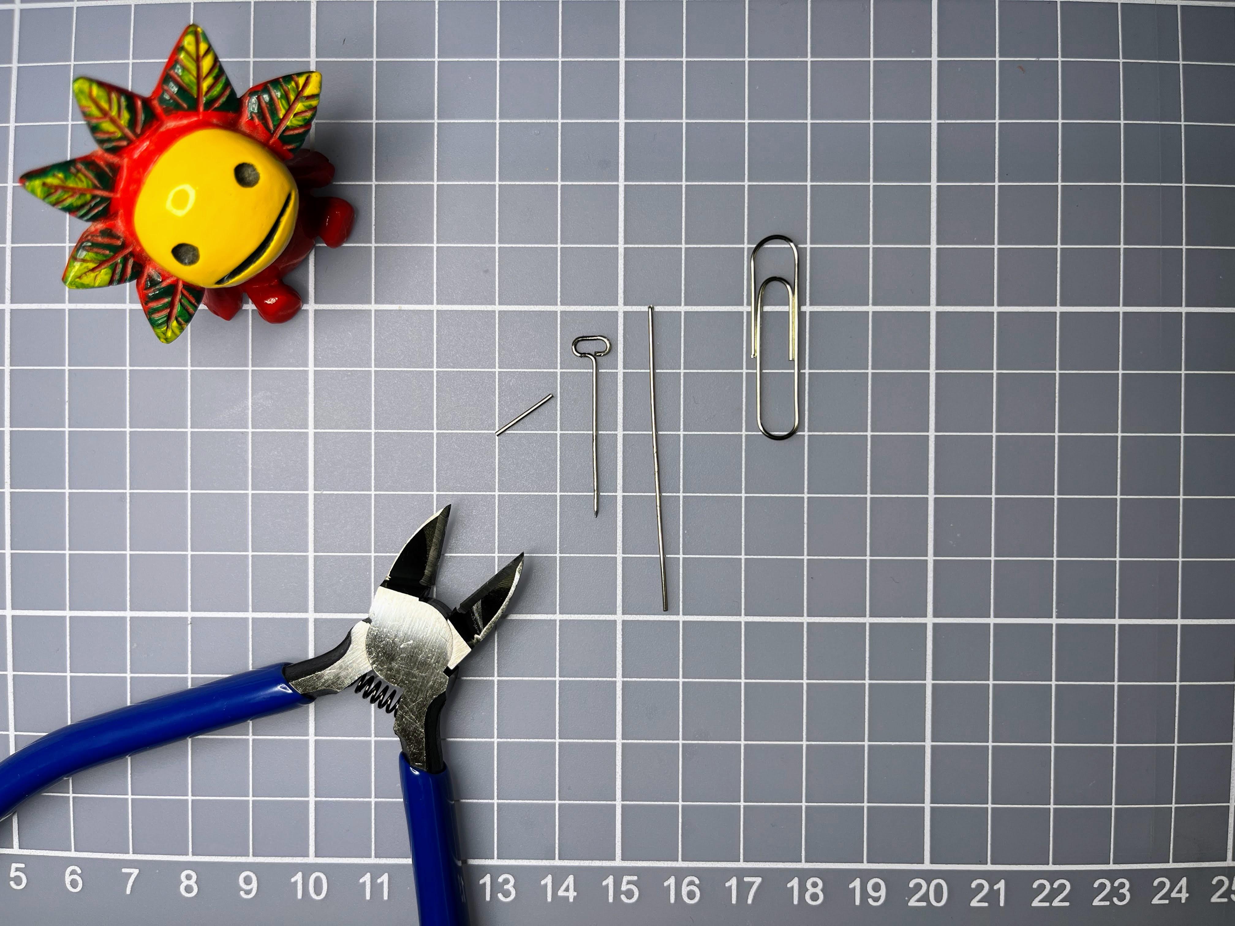
- Straighten the paperclip and cut into 2 pieces
- Keep 24mm straight and belt remaining into a handle
- Repeat to make 4 paperclip axis
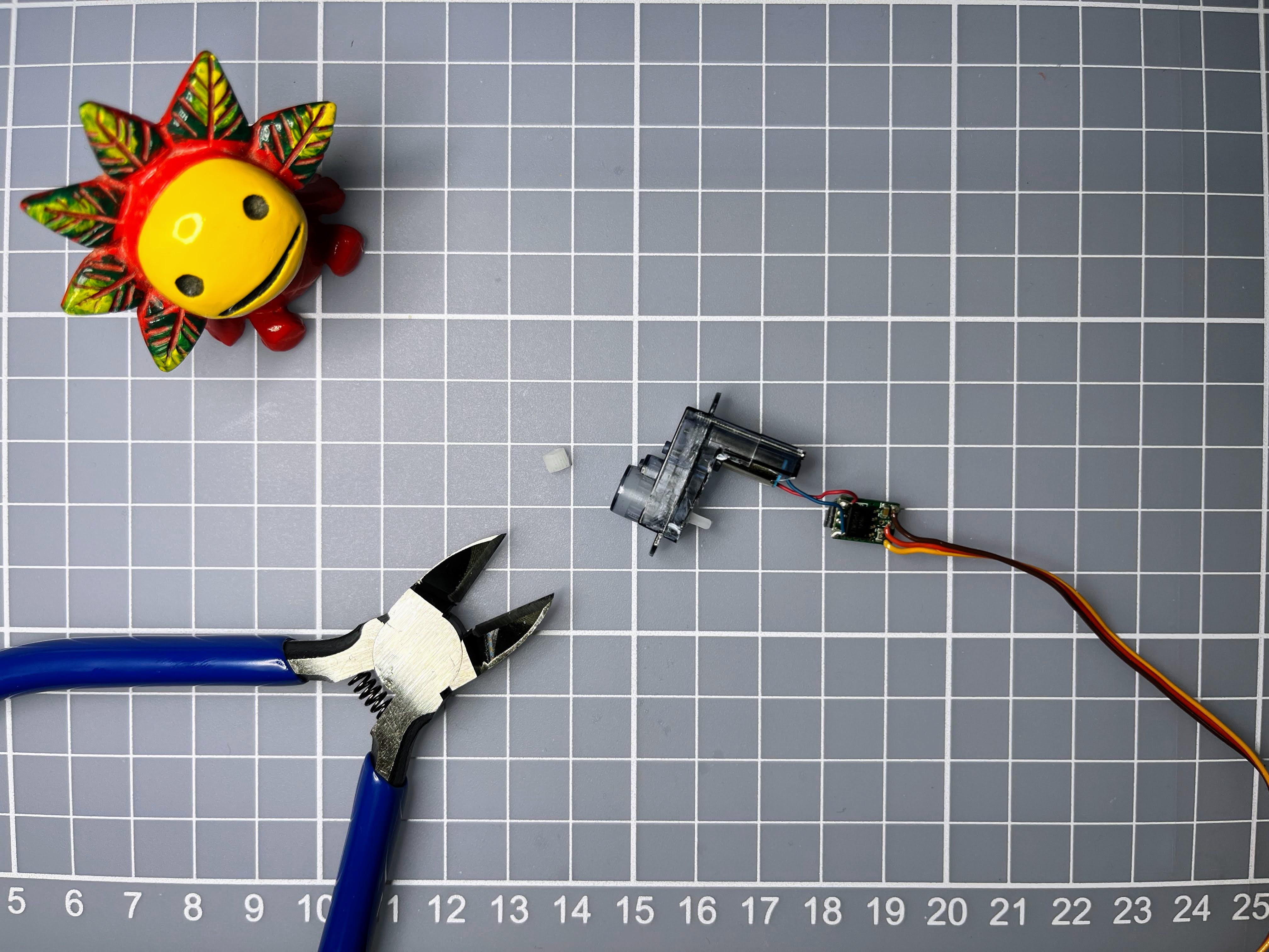
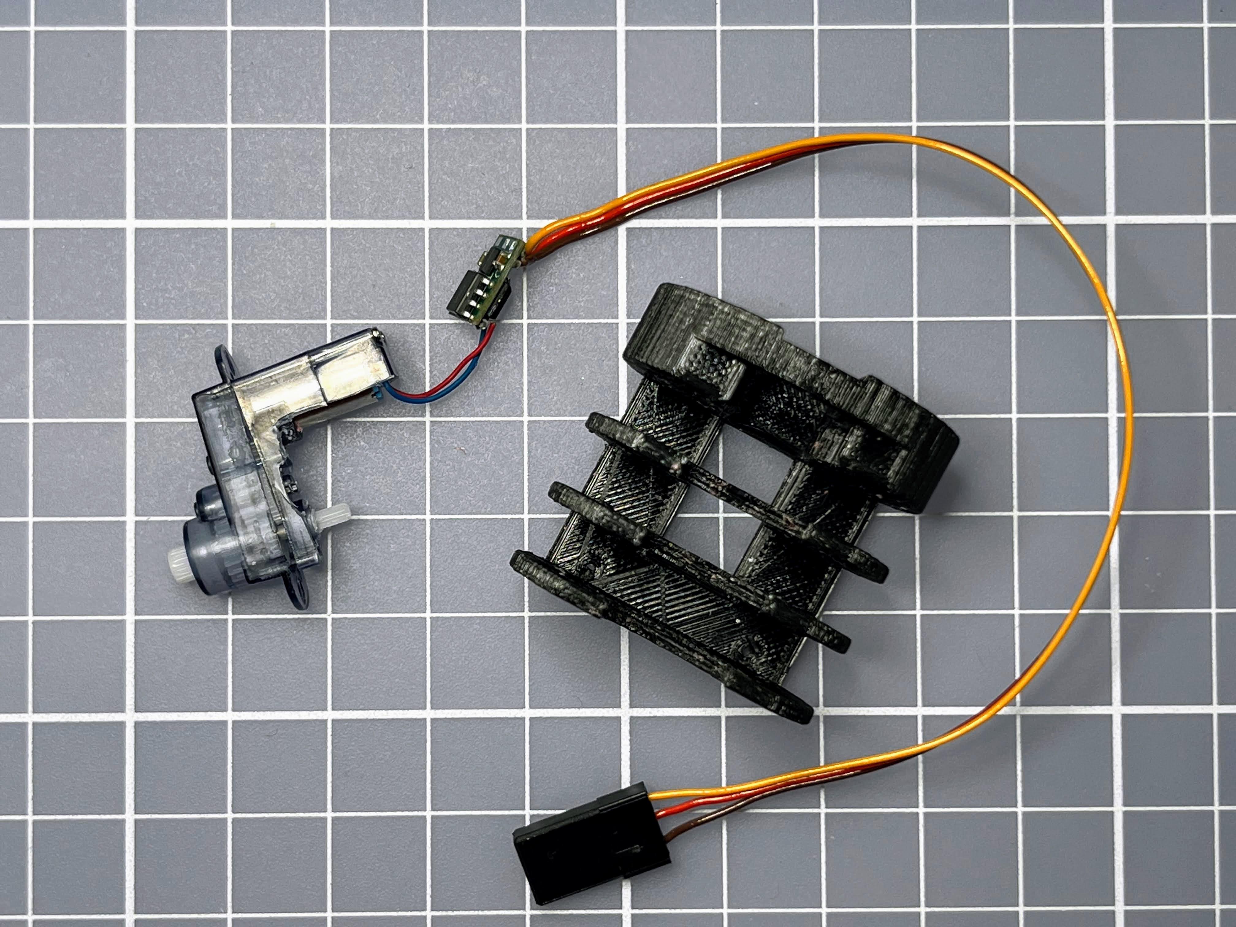
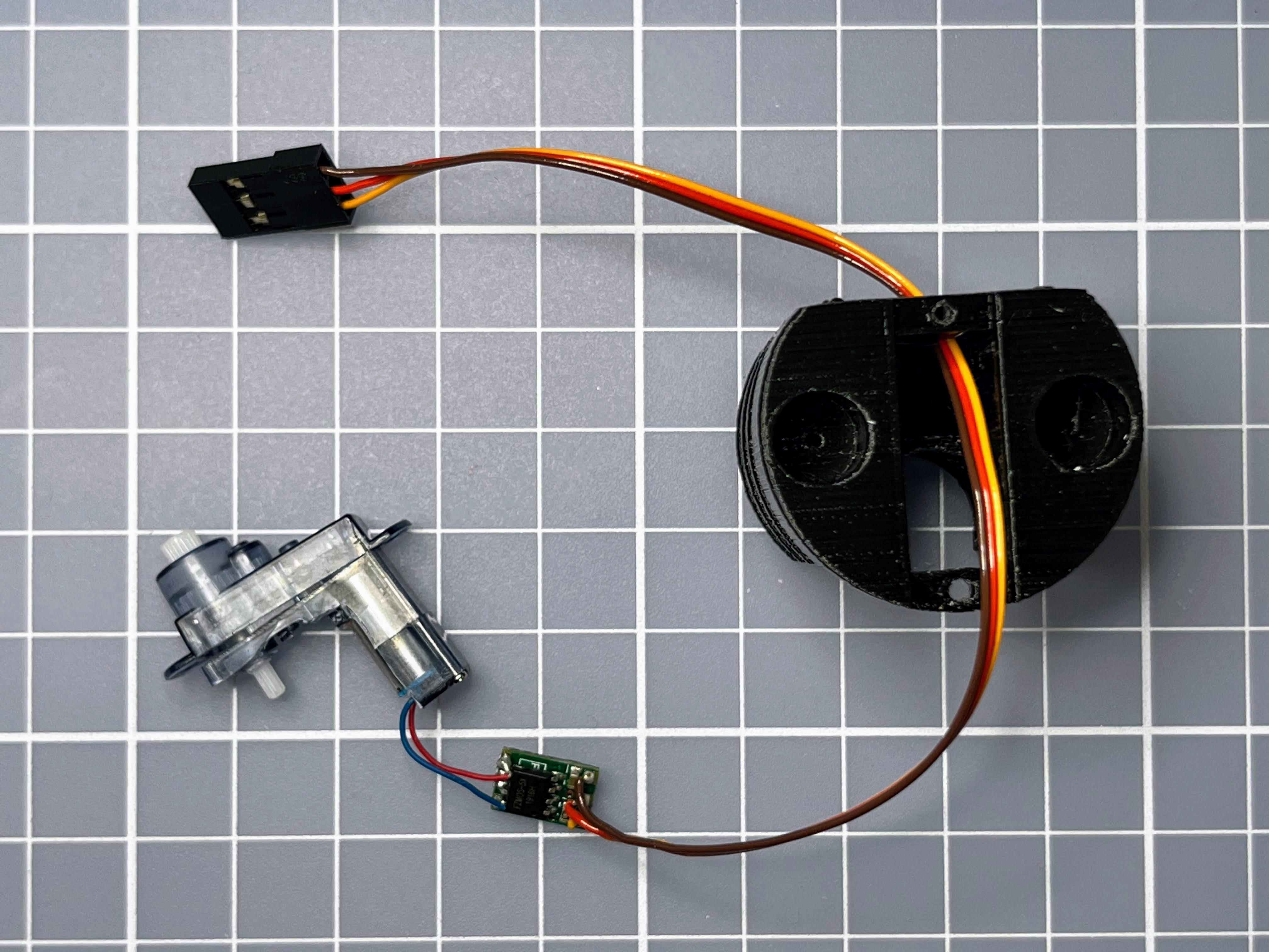
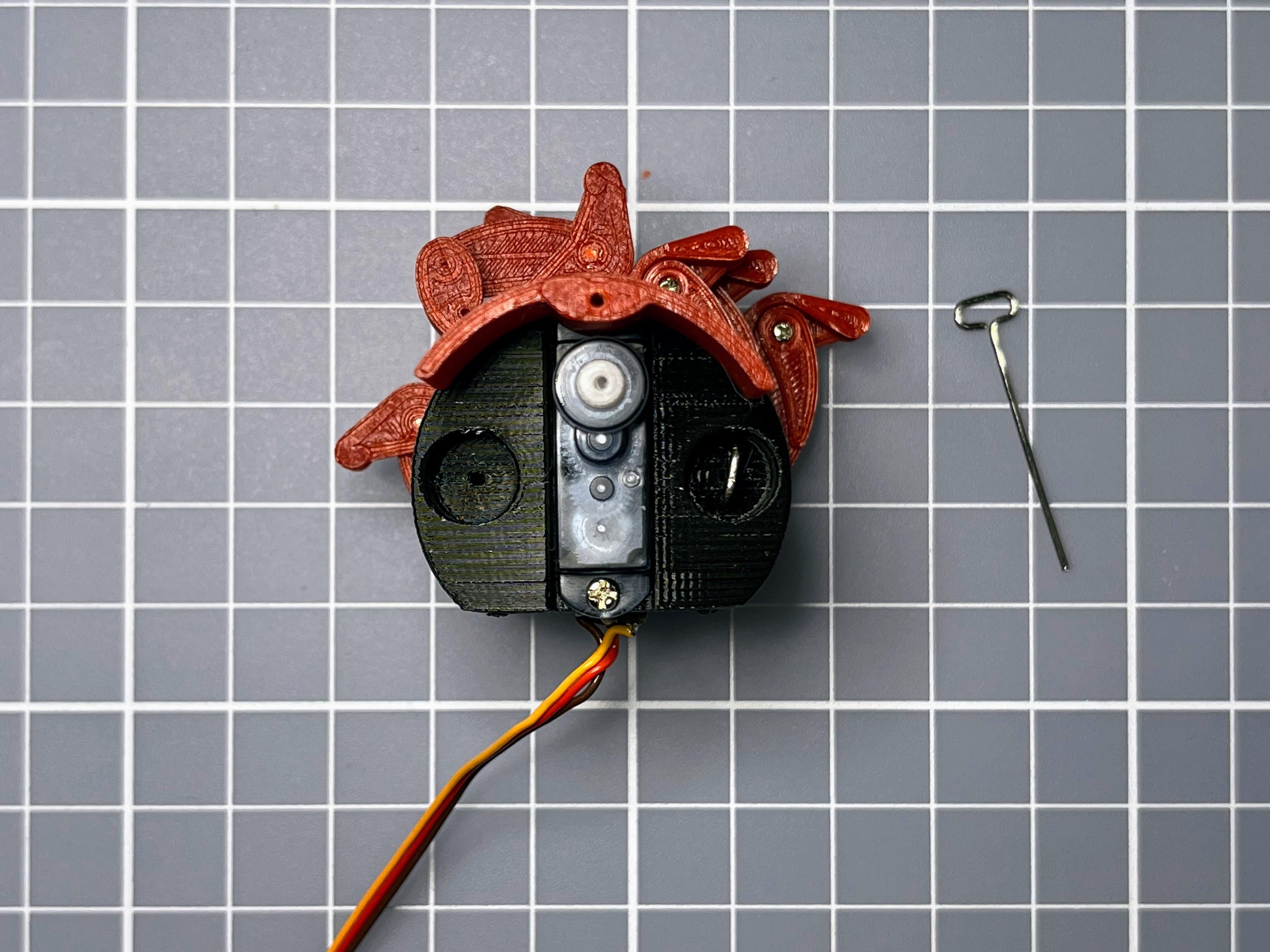
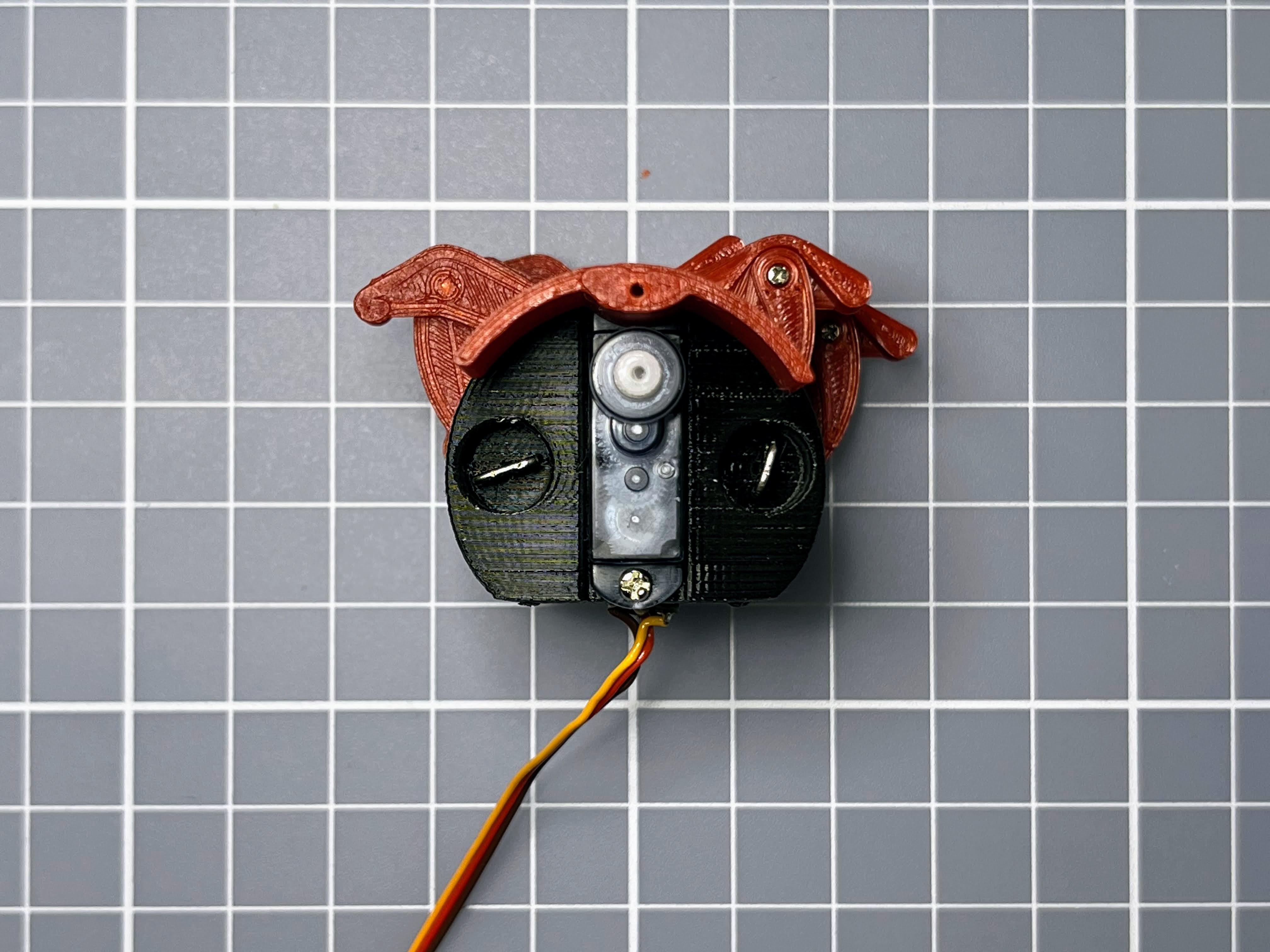
Servo Patch
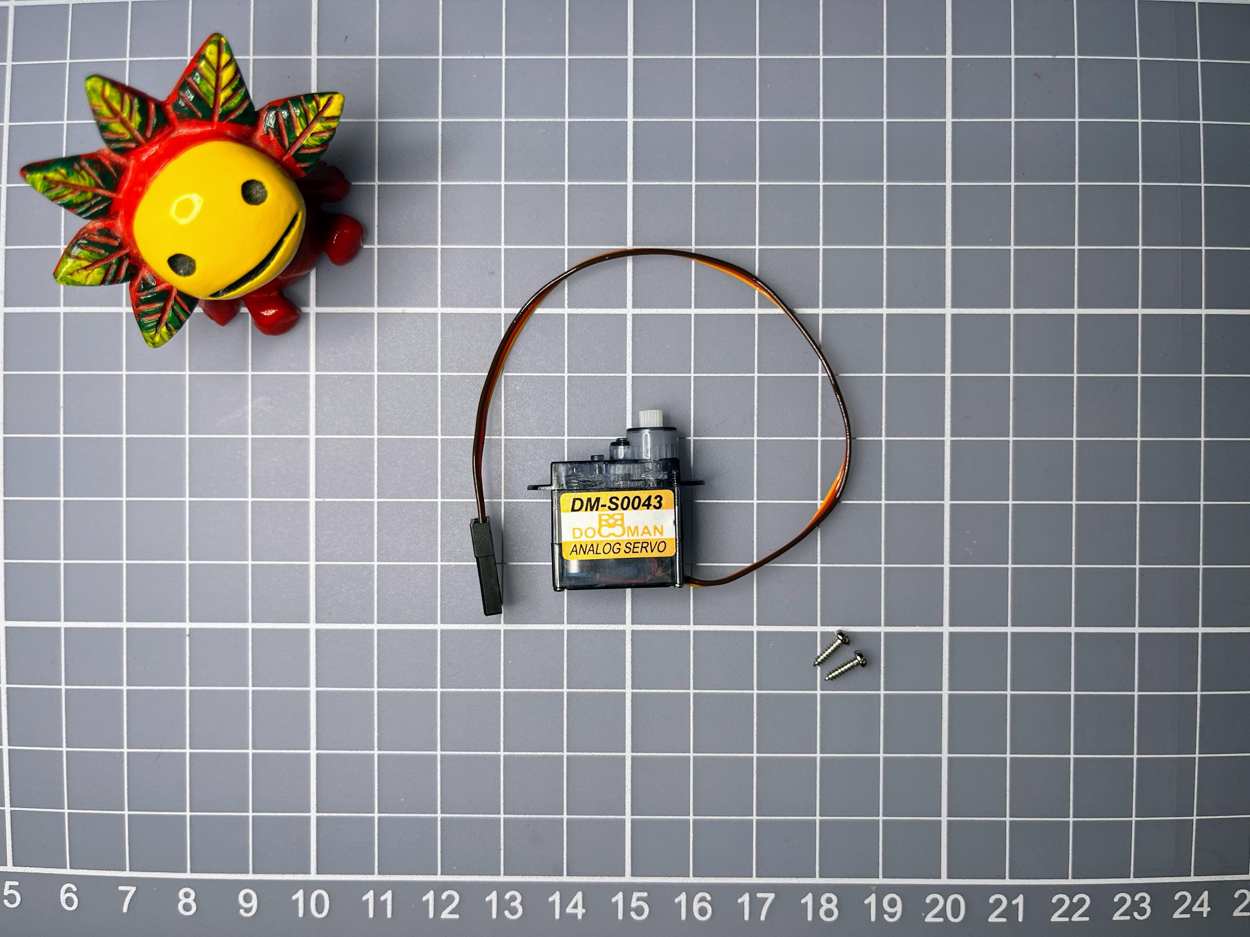
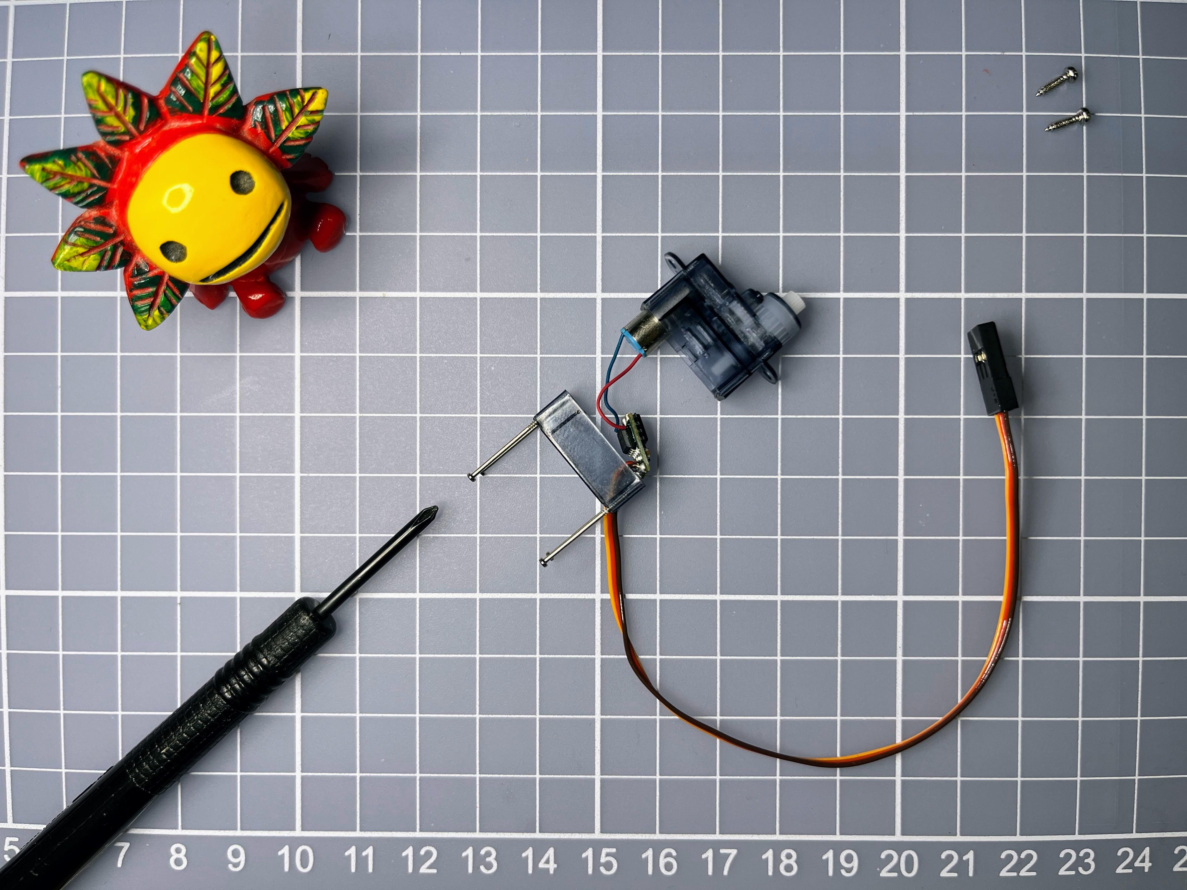
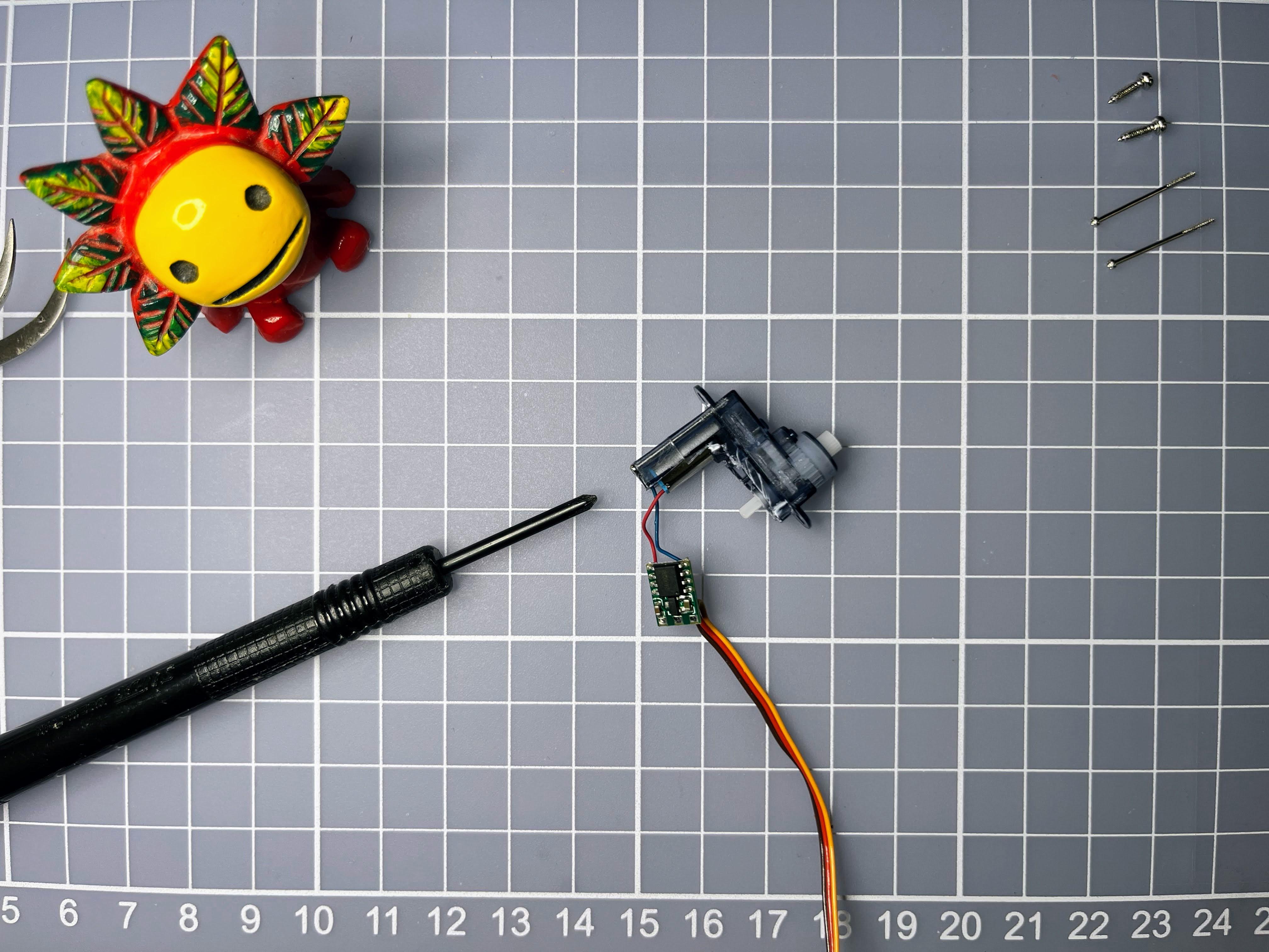
Picture 1: 4.3g 360 servo
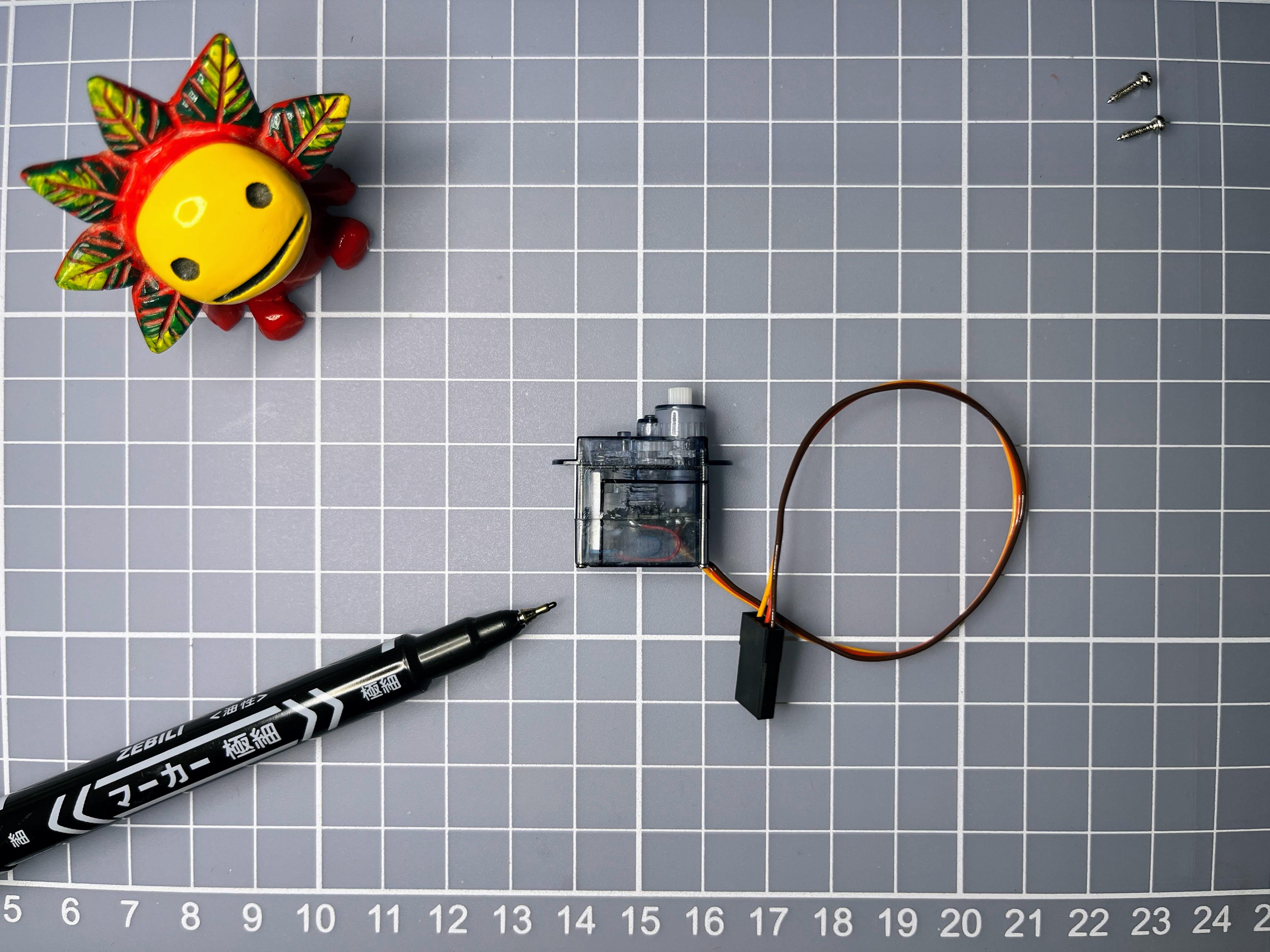
Picture 2: mark the cutting lines
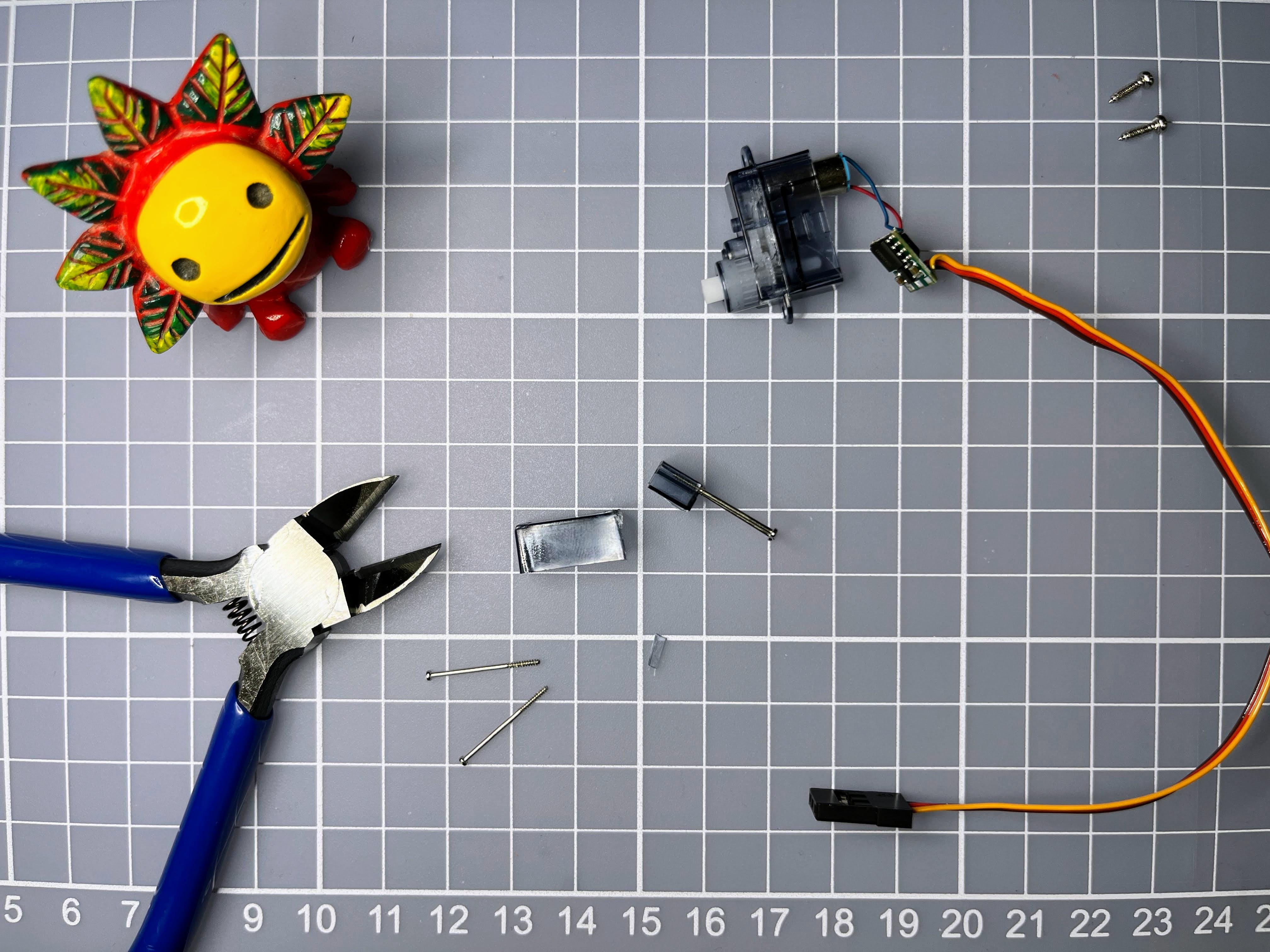
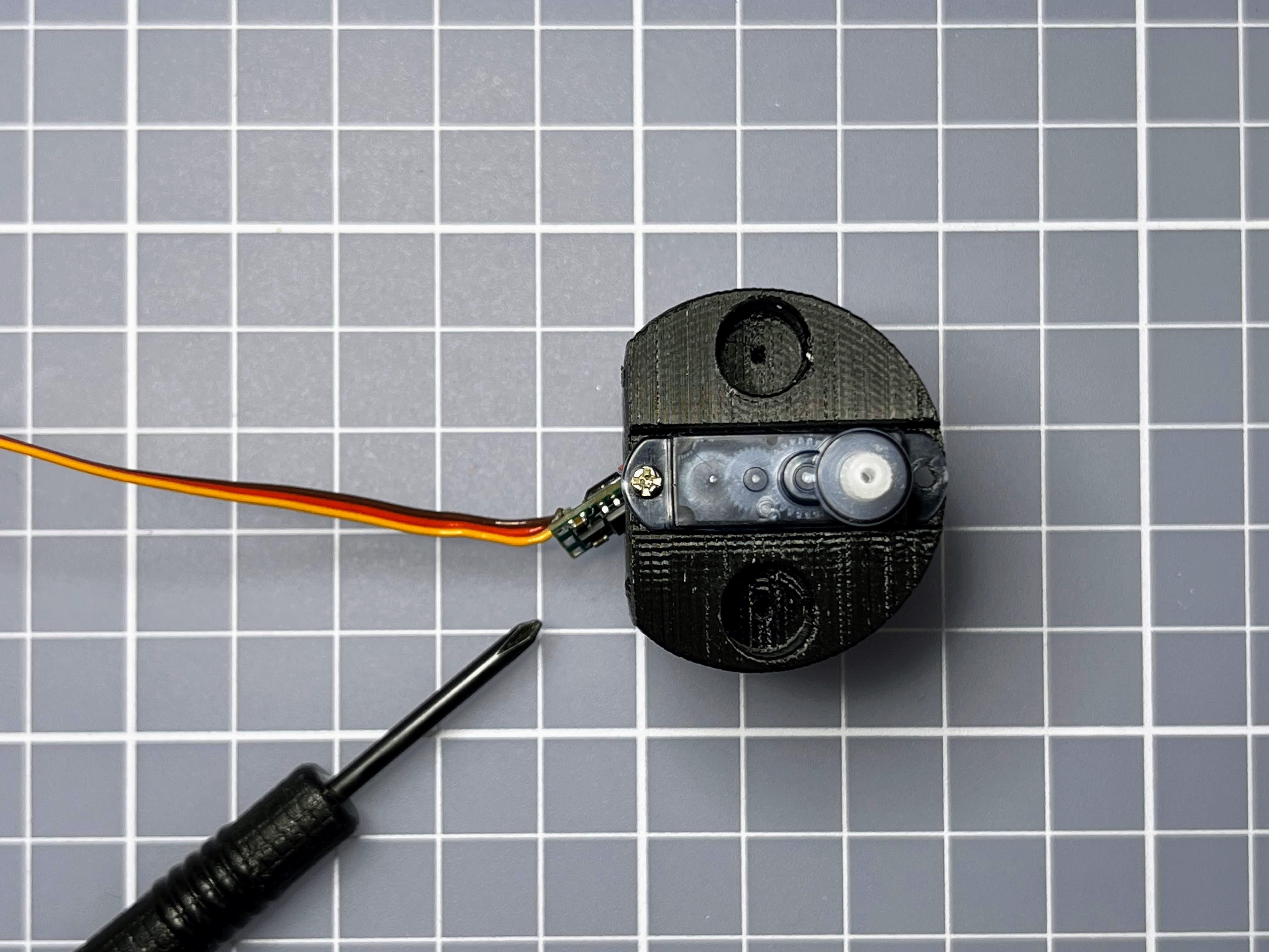
Picture 3: unscrew the servo
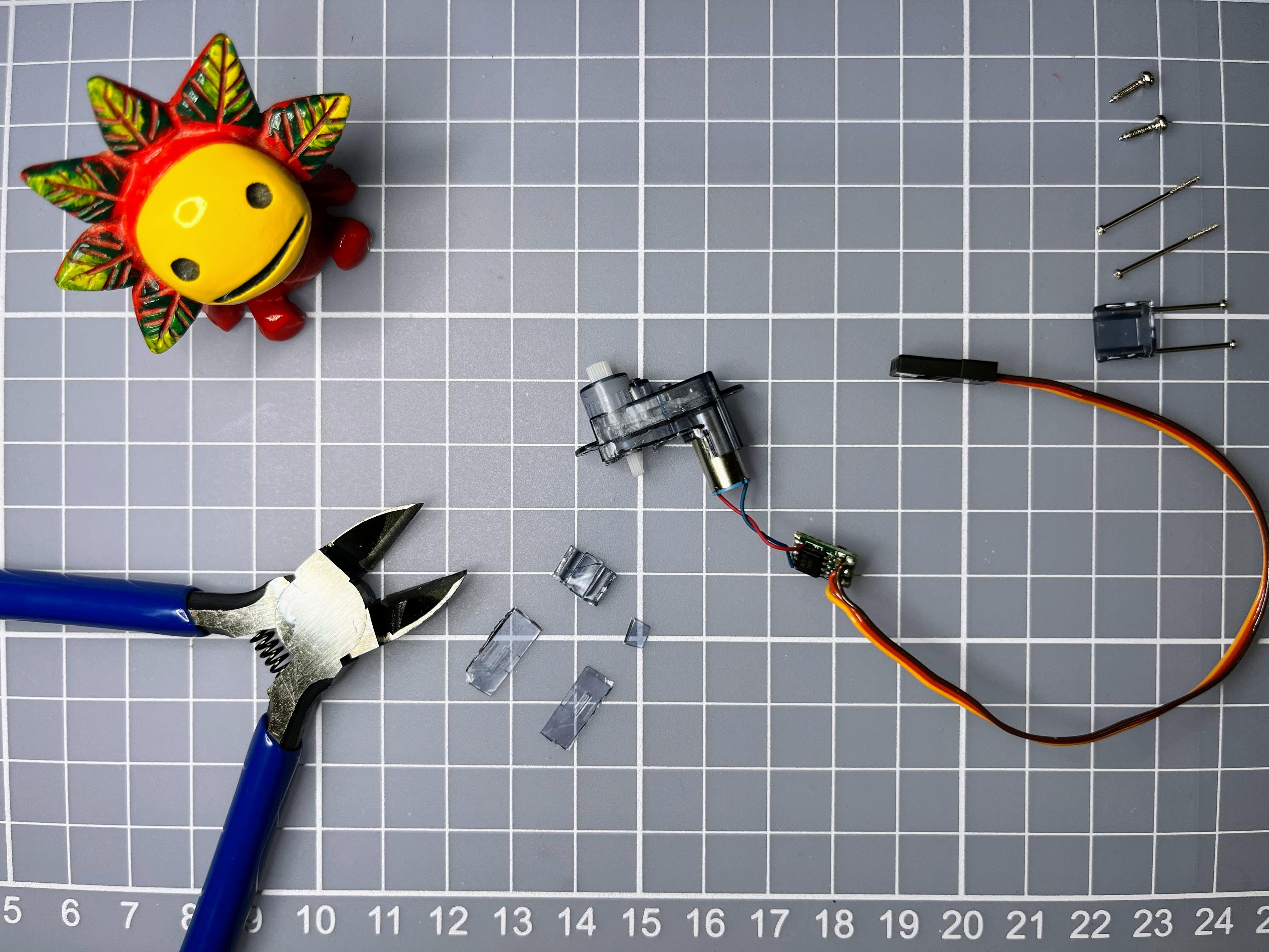
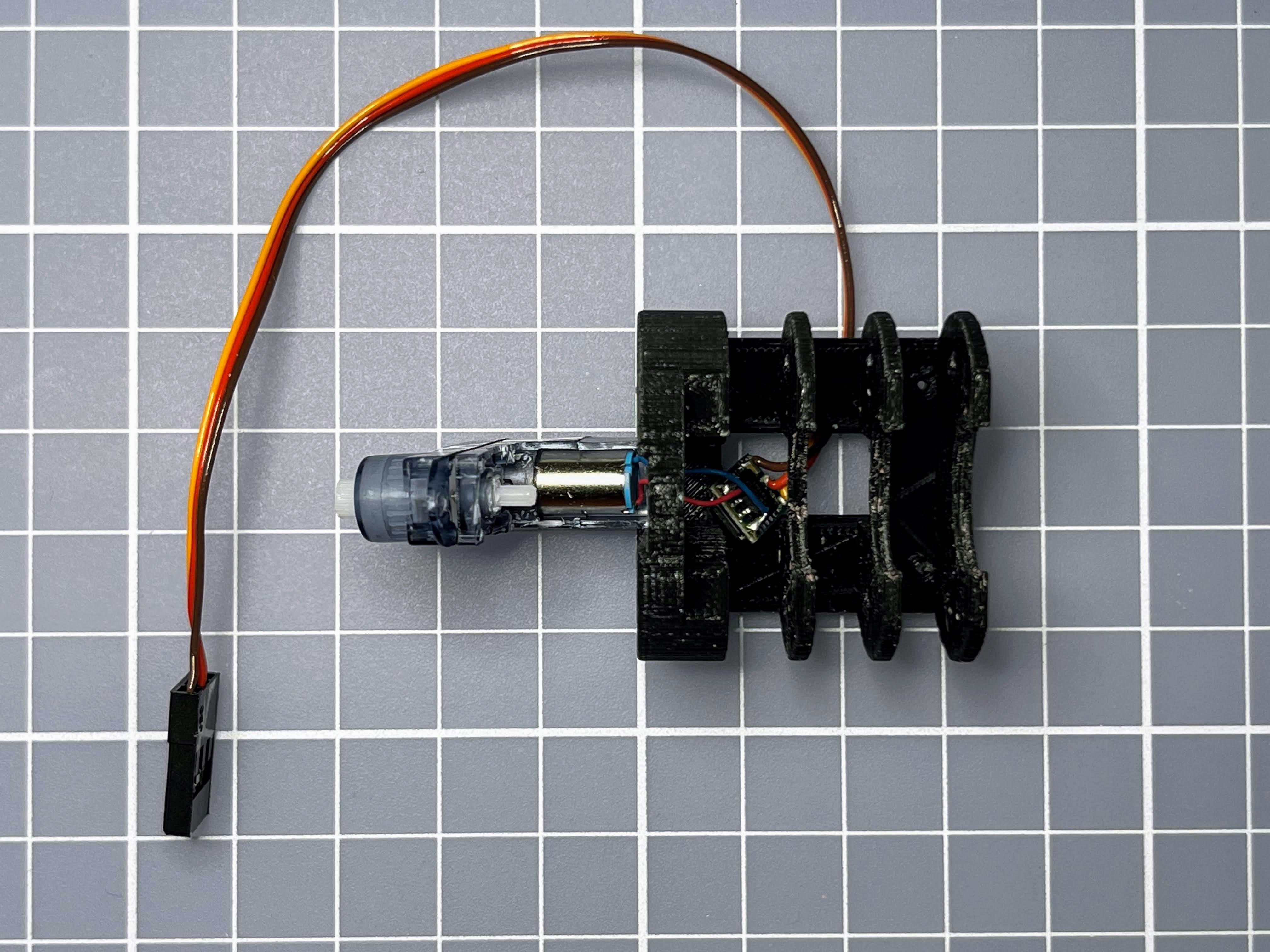
Picture 4-5: cut the servo
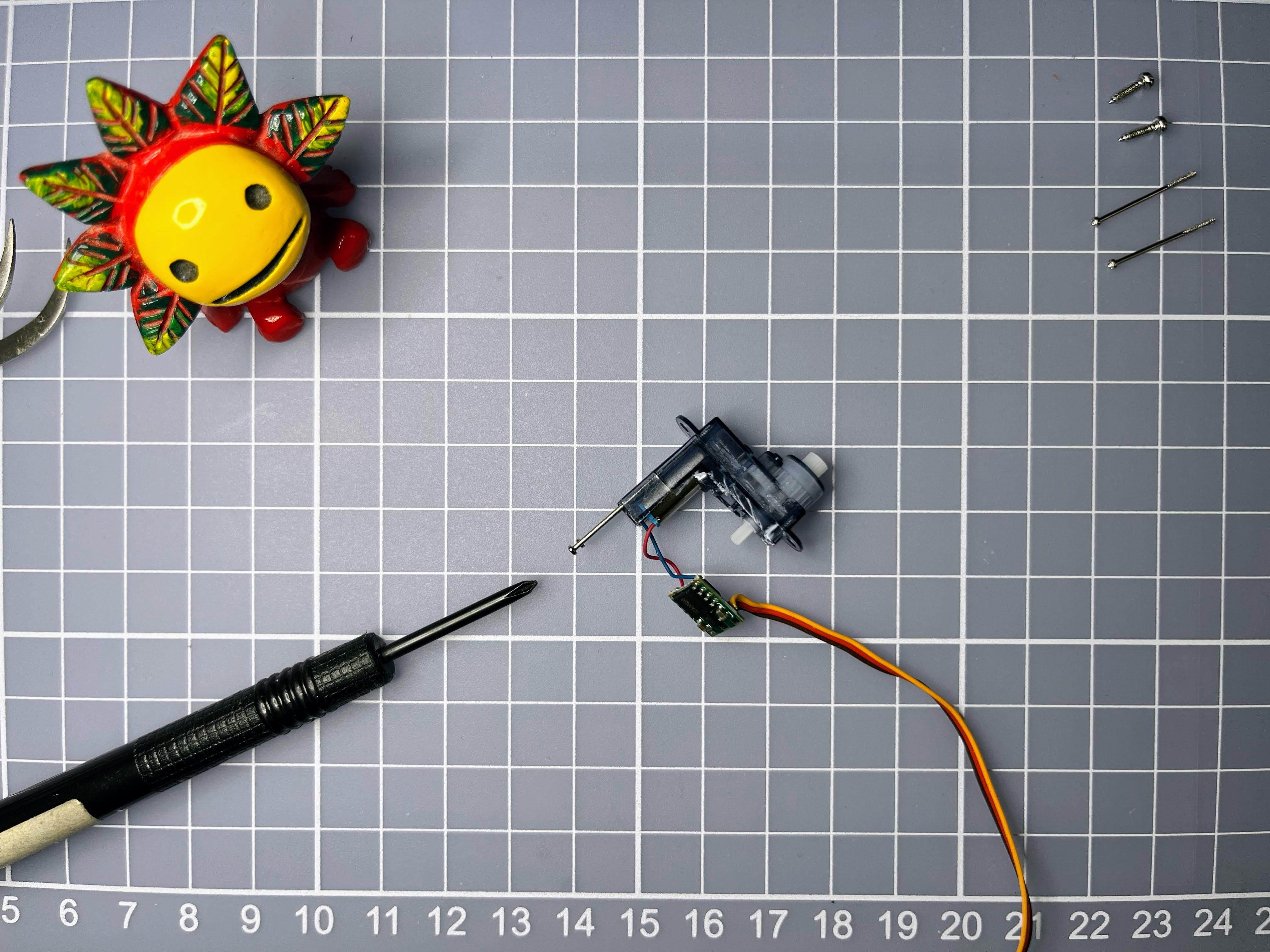
Picture 6-7: screw up the trimmed servo
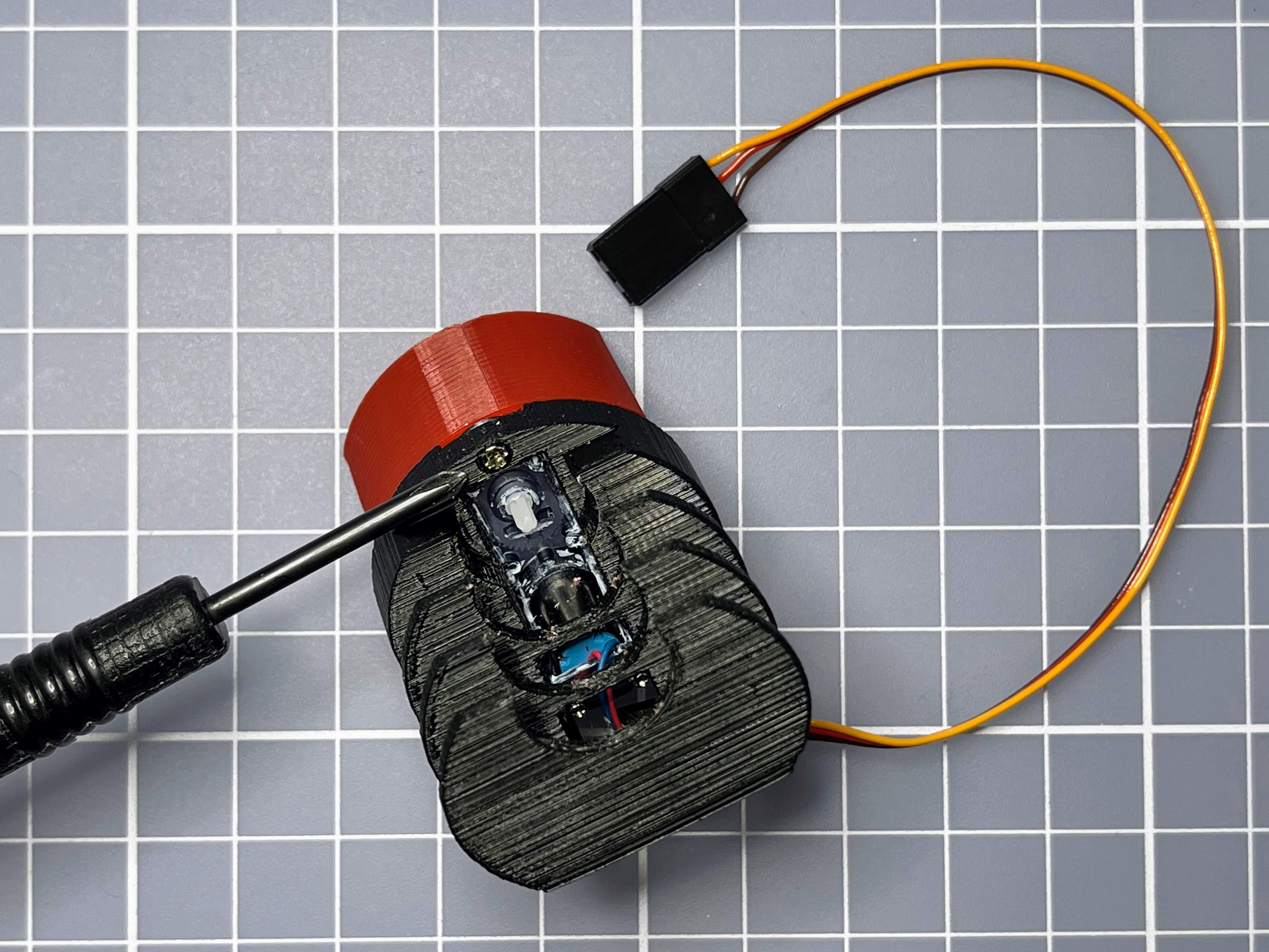
Picture 8: cut the original output axis
TTGO T-Journal Antenna Patch
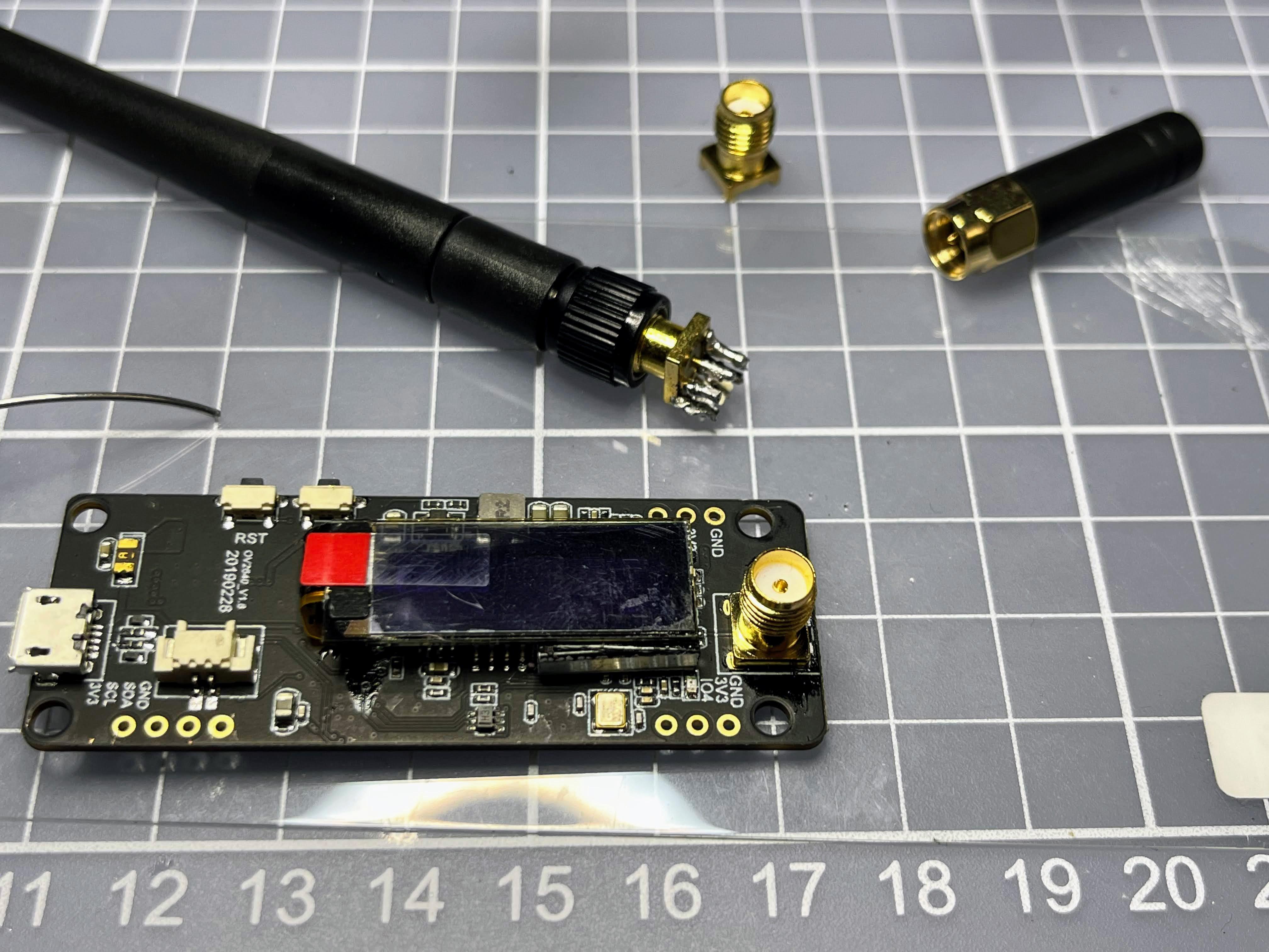
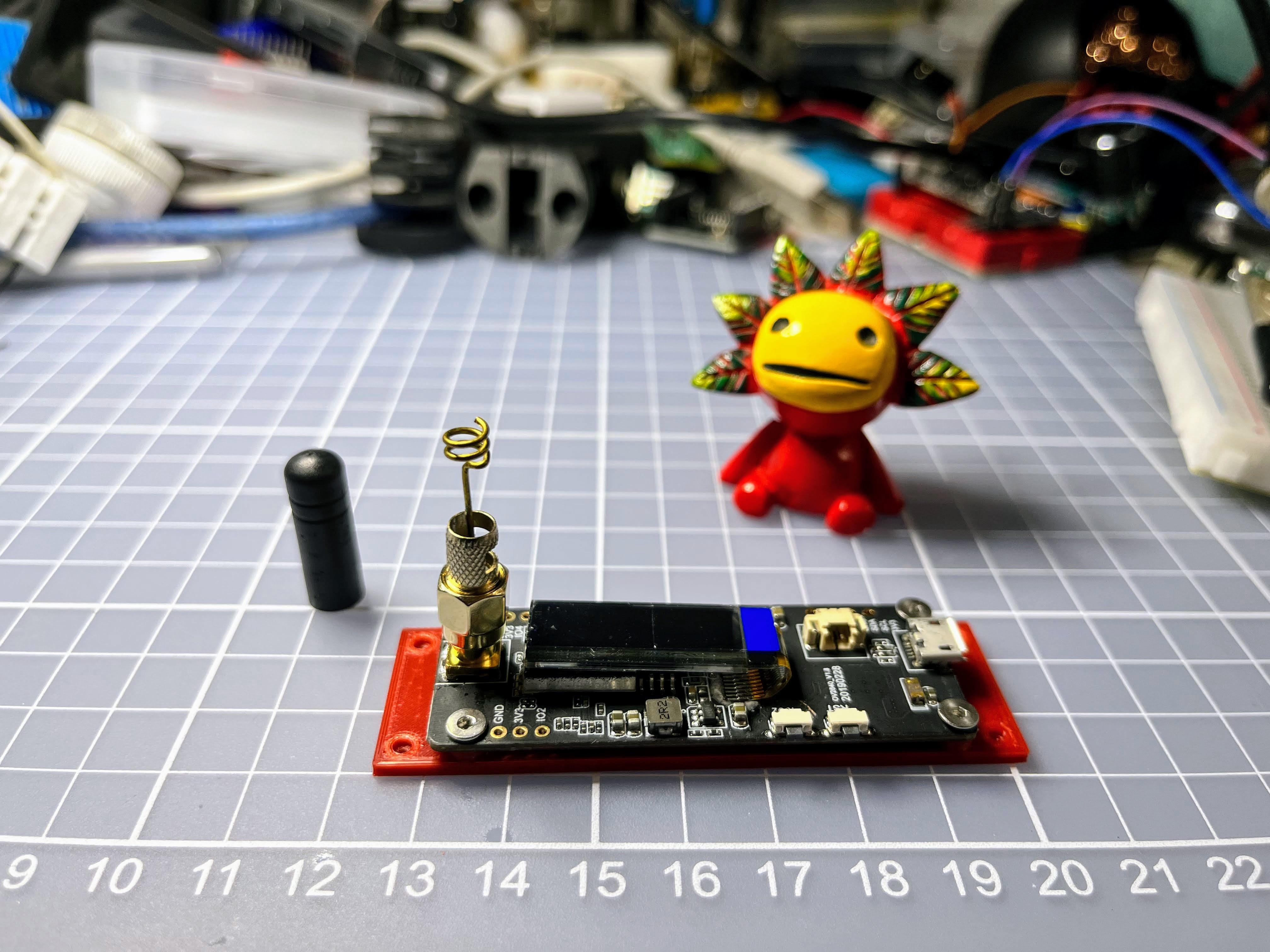
Desoldering the TTGO T-Journal SMA edge mount Jack and replace with PCB mount jack.
3D Print
Please download and print all the parts at Thingiverse:
https://www.thingiverse.com/thing:5115055
Legs Assembly
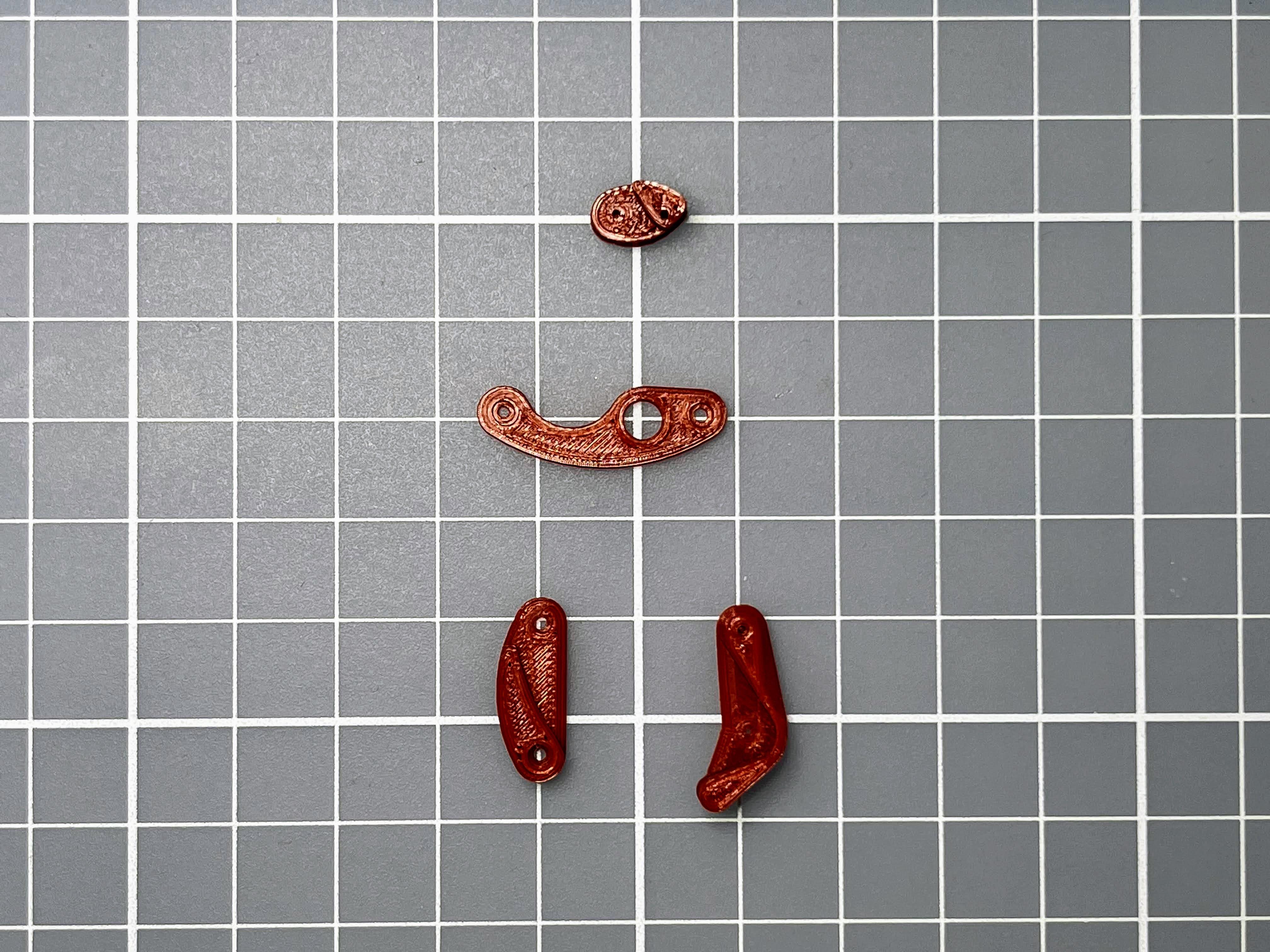
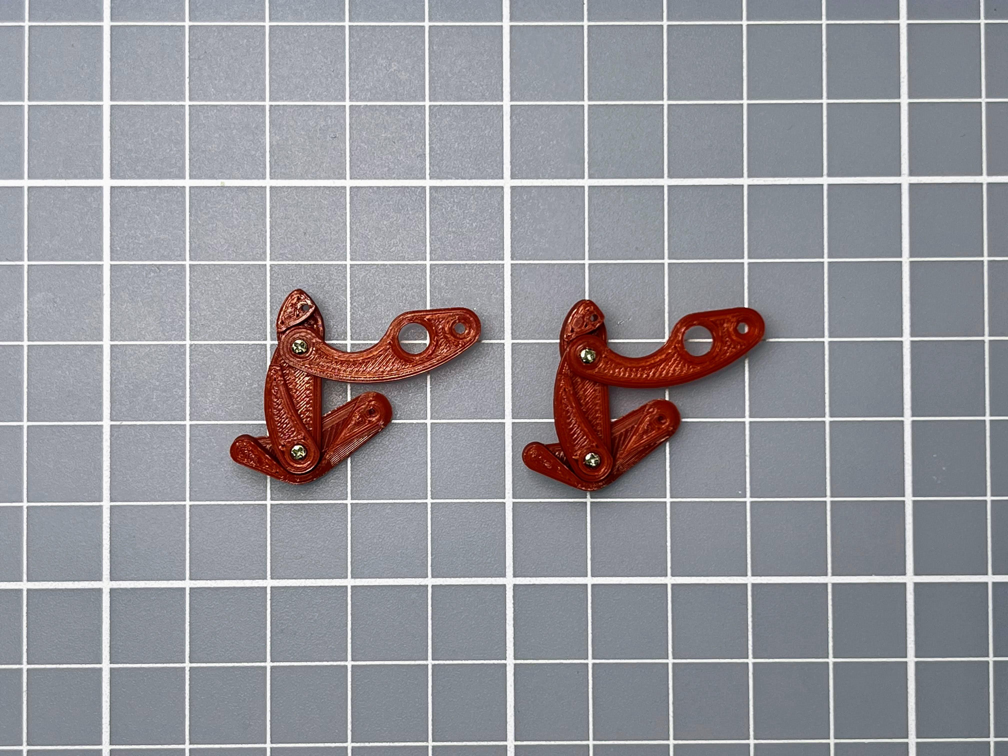
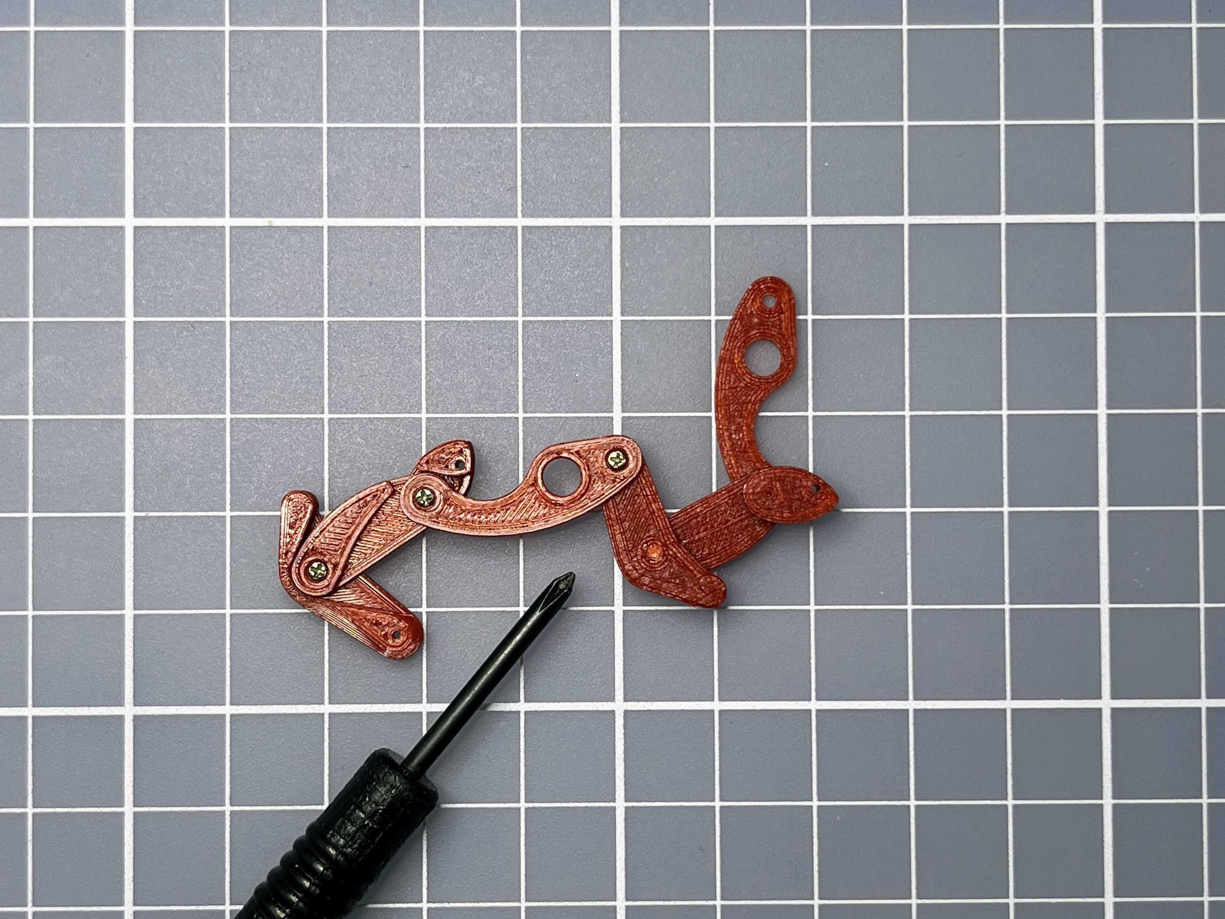
Picture 1: leg1-4
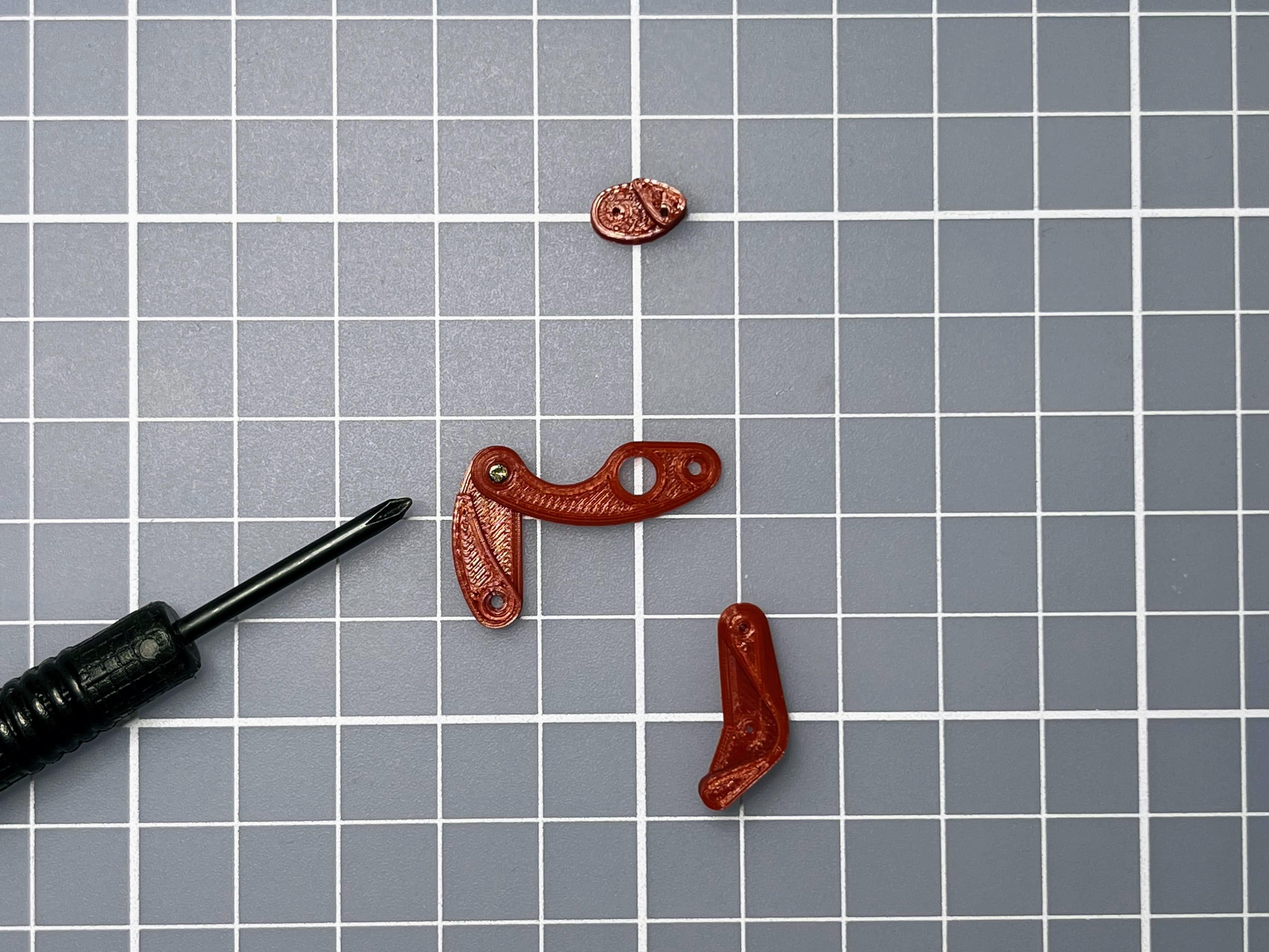
Picture 2: connect leg2 and leg3 with screw
Picture 3: then connect to leg1
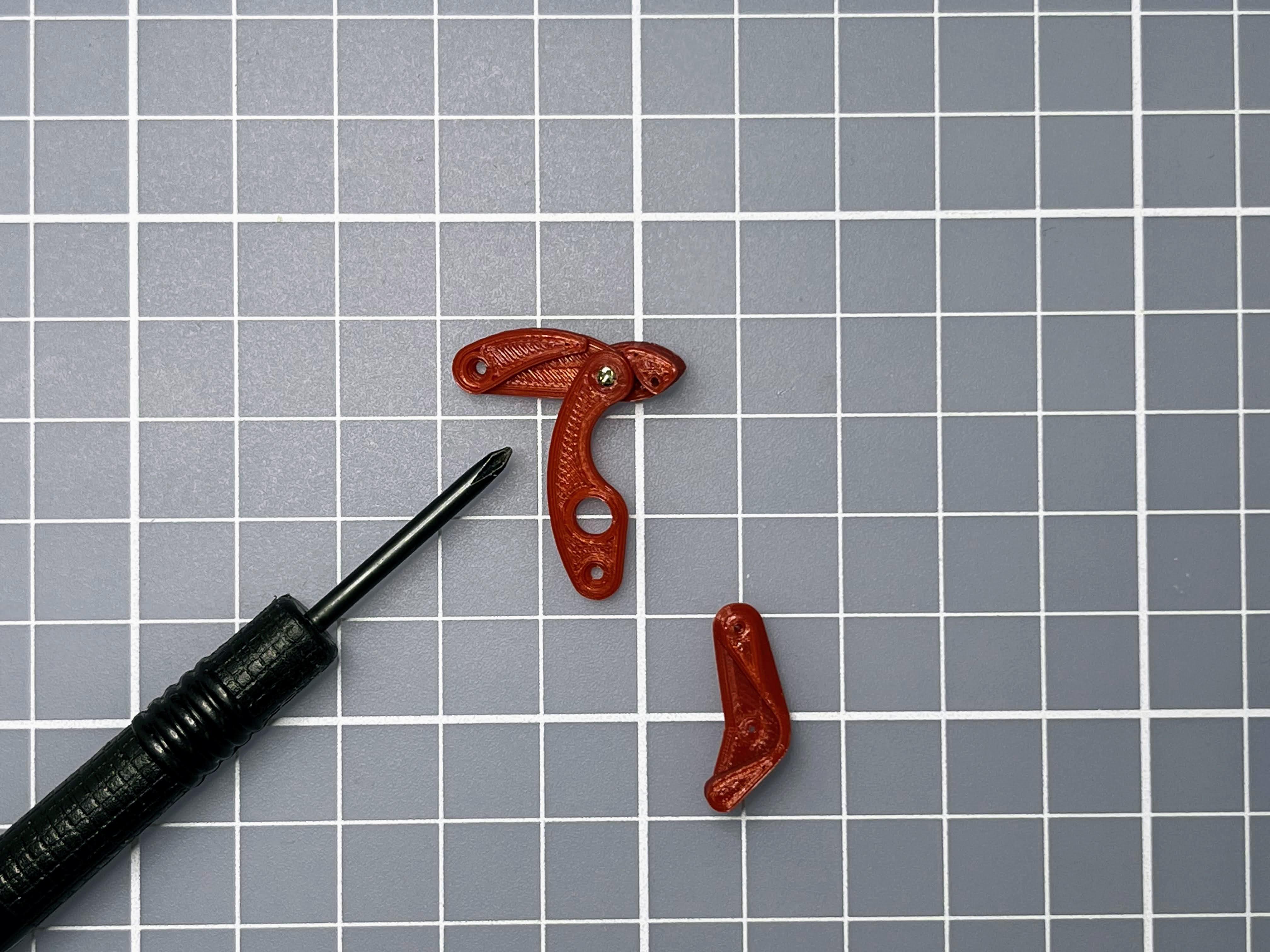
Picture 4: connect leg3 and leg4 with screw
Picture 5: repeat Picture 1-4 to assembly 1 more
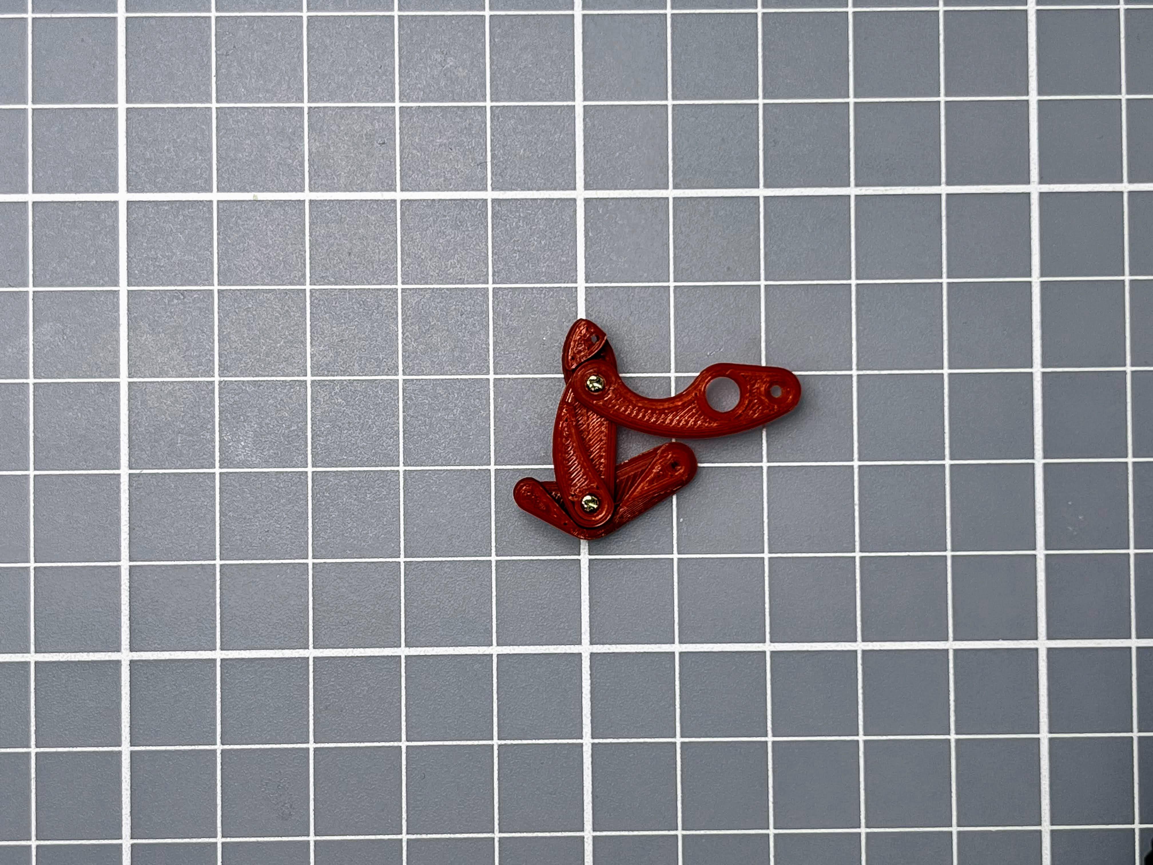
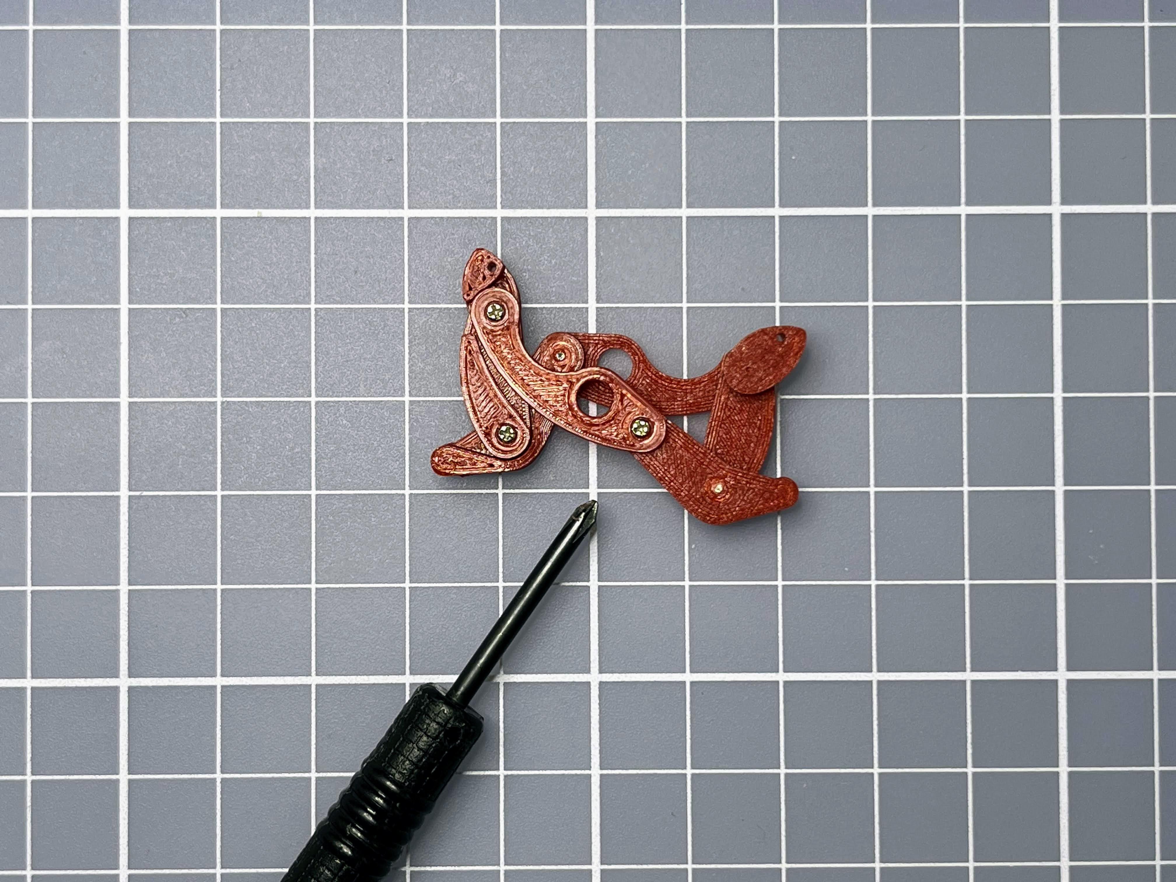
Picture 6: connect leg2 and leg4 with screw
Picture 7: connect another leg2 and leg4 with screw
Repeat Picture 1-7 to assembly 6 pairs of legs.
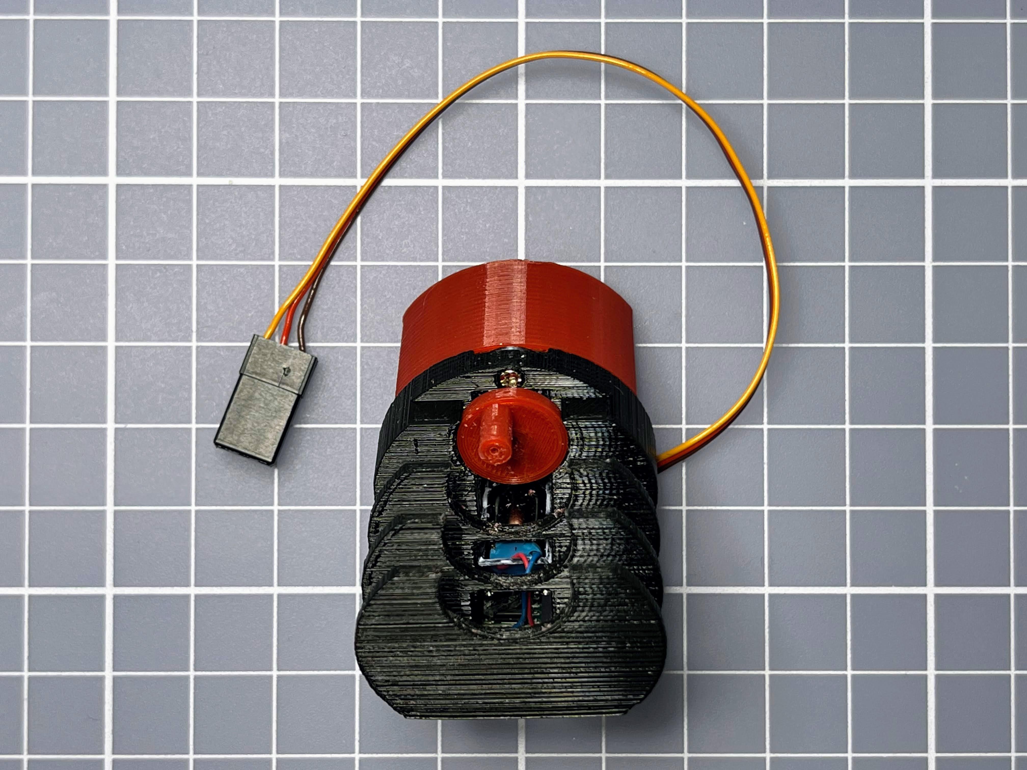
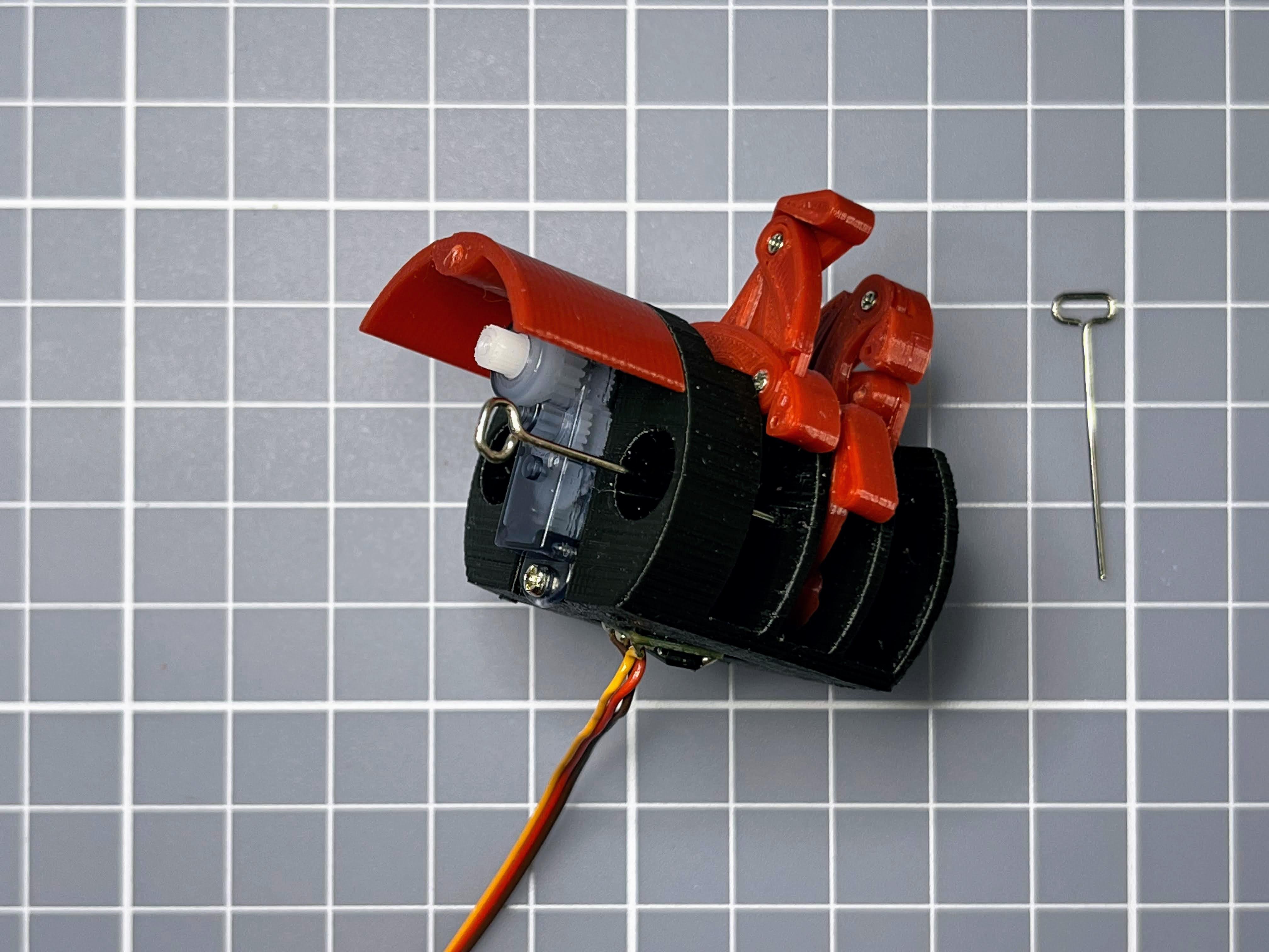
Install Servo
Picture 1: servo and body
Picture 2: put the wire into the body hole
Picture 3: push servo into the body
Picture 4: screw up upper side
Picture 5: screw up with bottom
Install Crankshaft and Legs
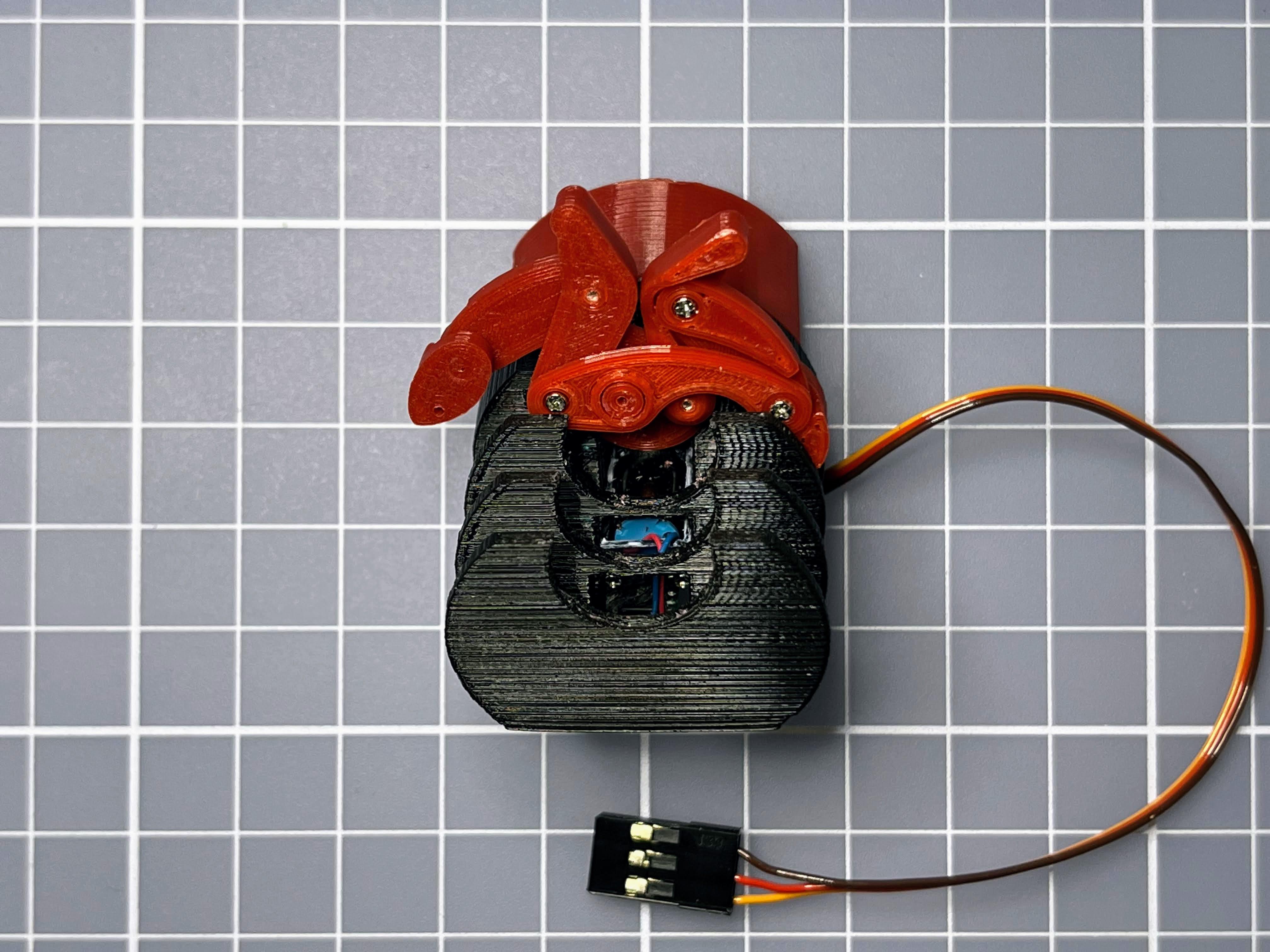
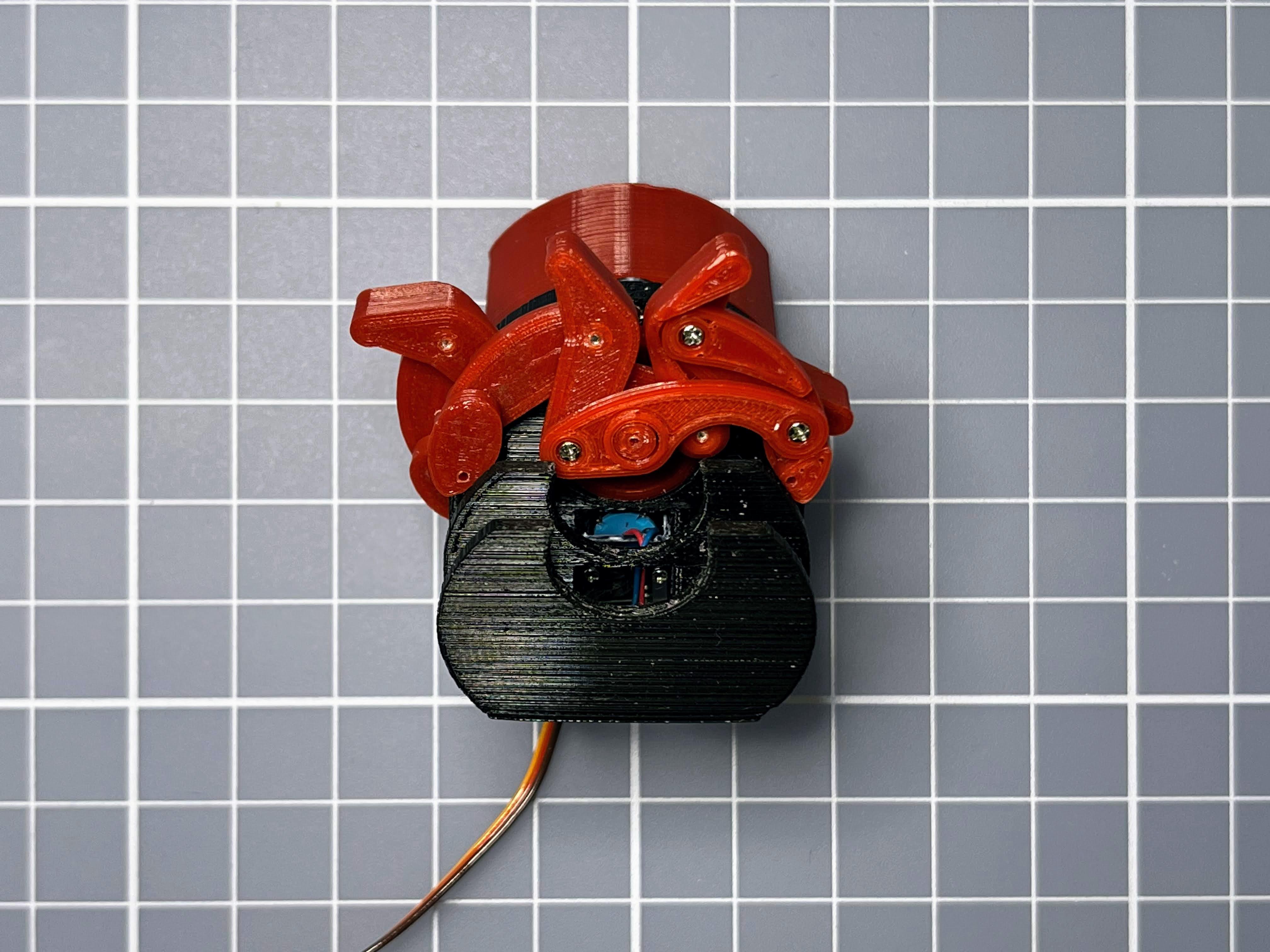
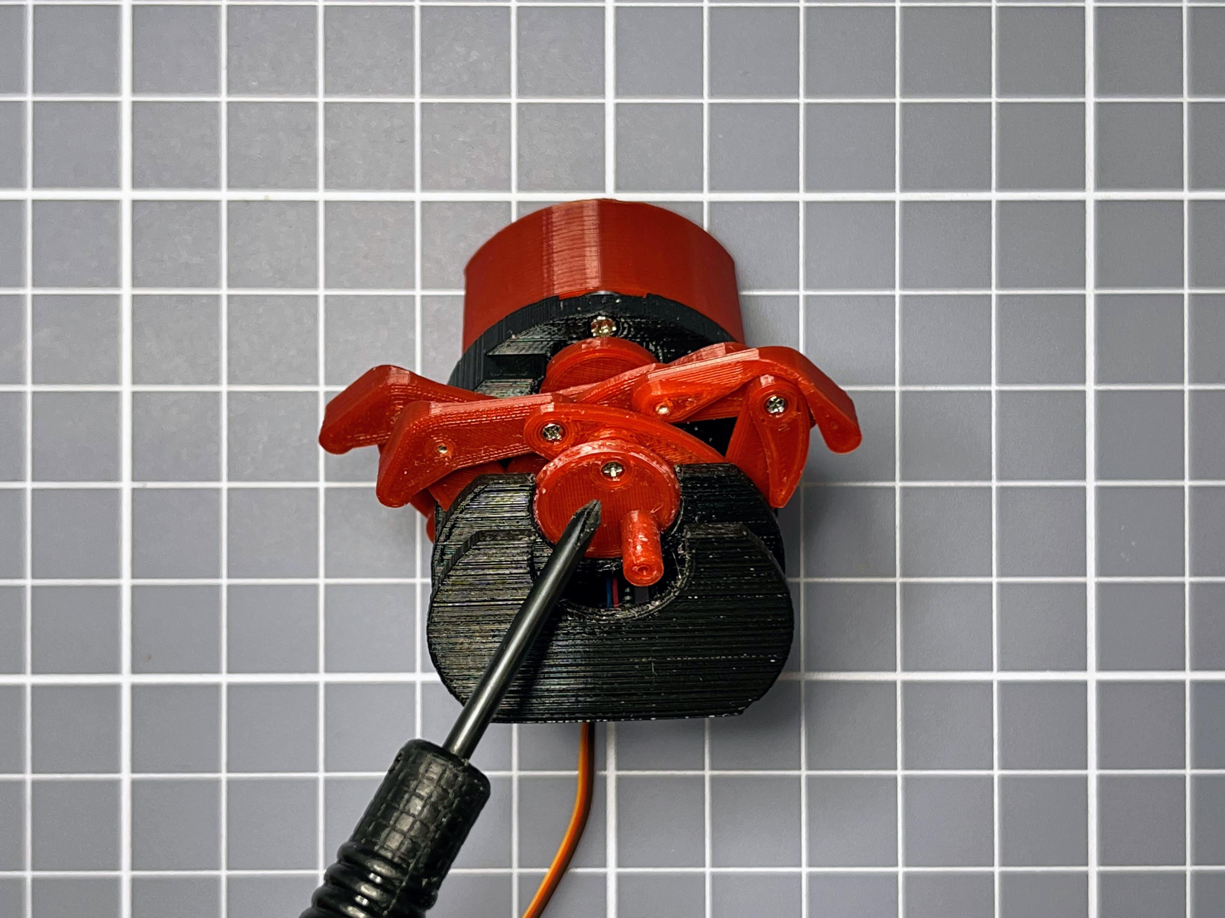
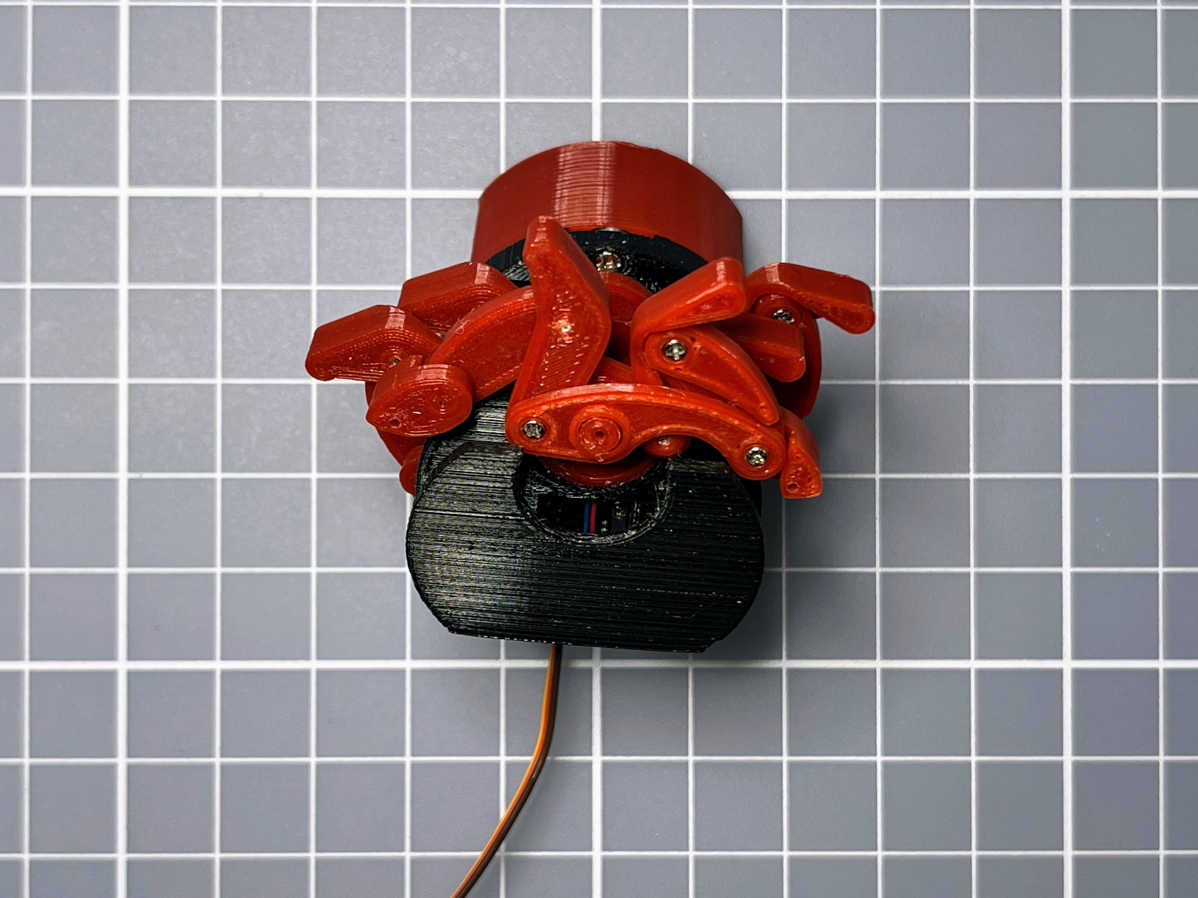
Picture 1: install axis1 into servo axis
Picture 2: install pair of legs into axis1
Picture 3: install axis2
Picture 4: install next pair of legs into axis2
Picture 5: install next axis2
Picture 6: install last pair of legs into axis2
Picture 7: instal axis3
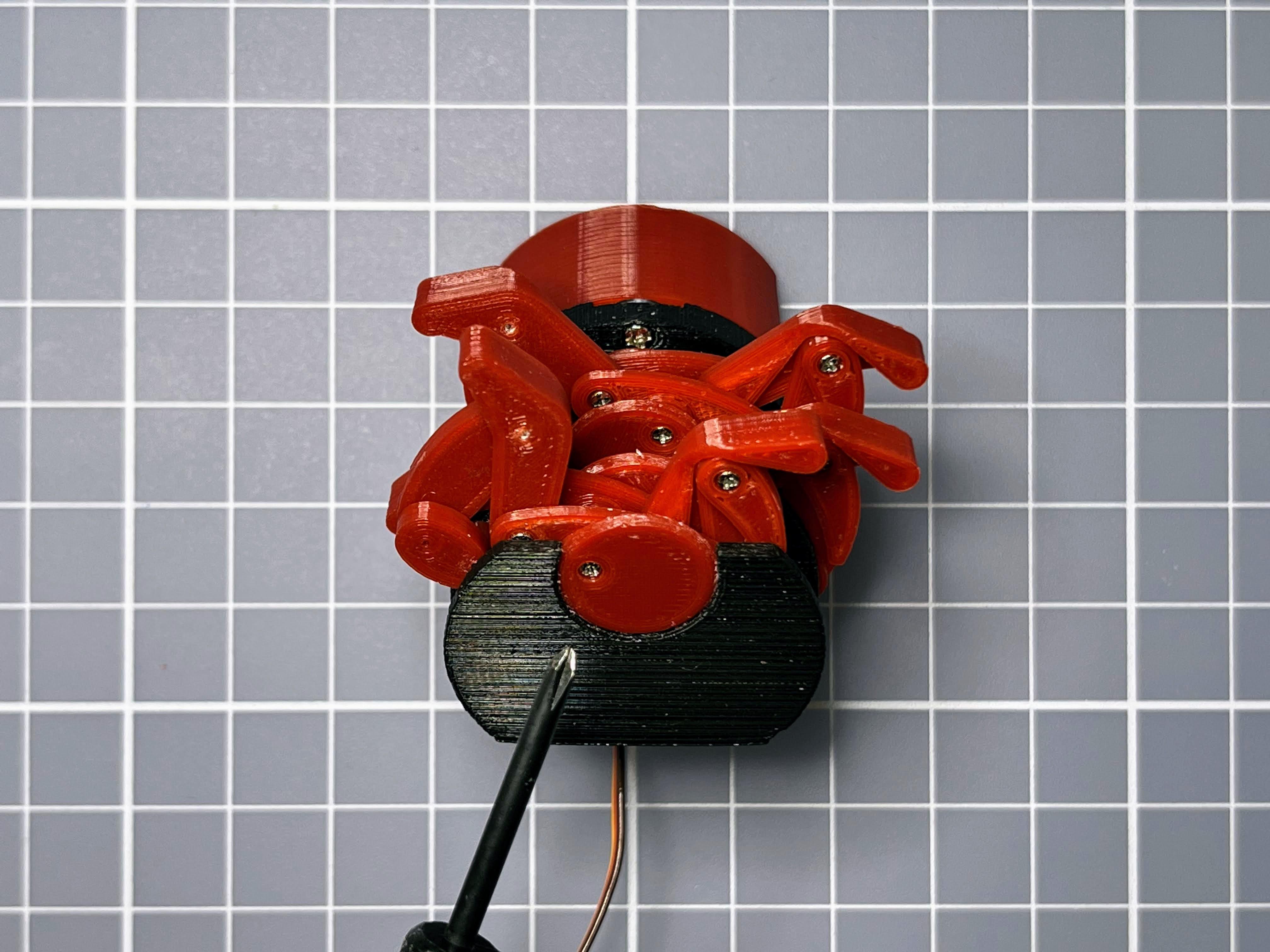
Install Paperclip Axis
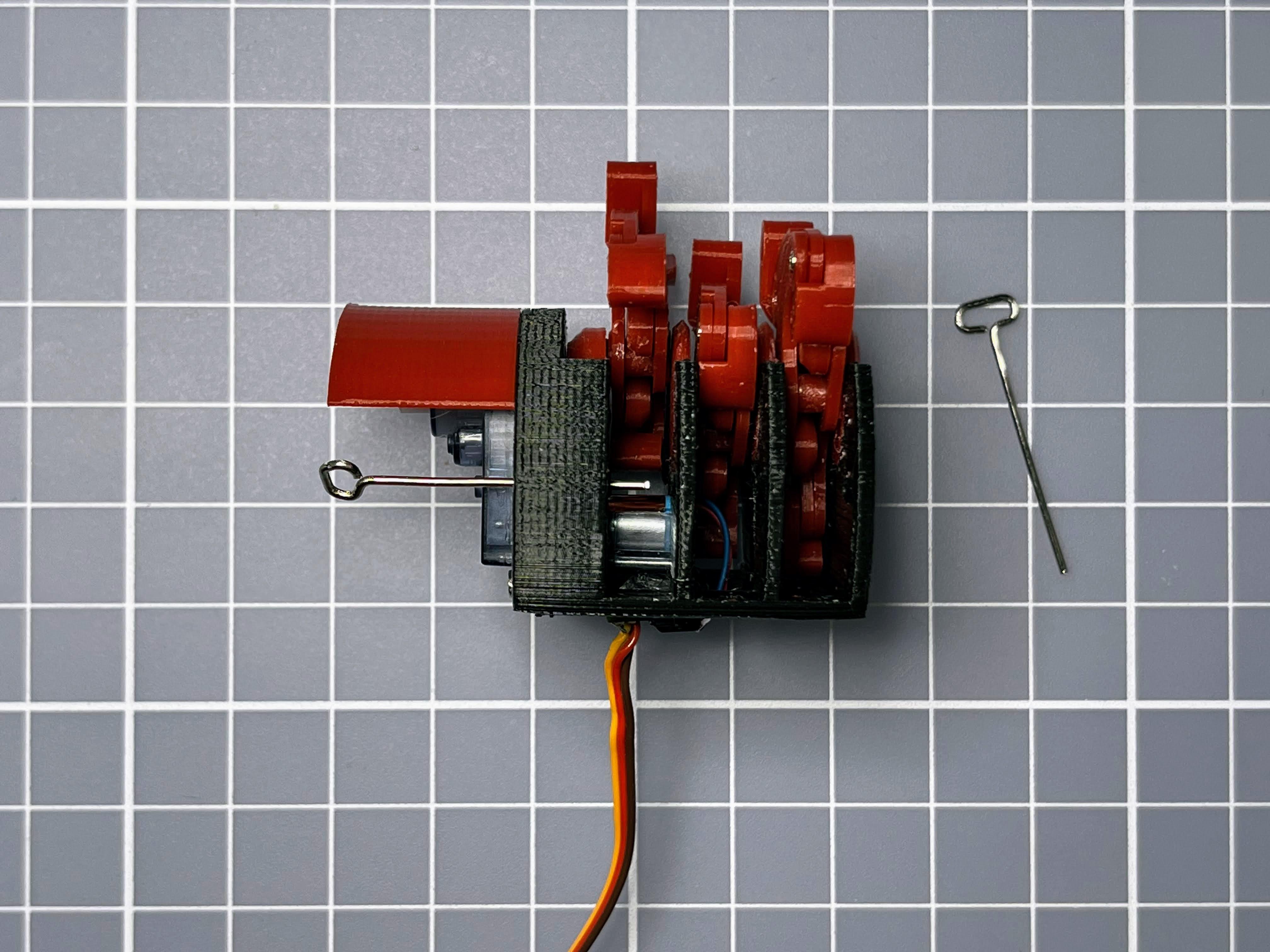
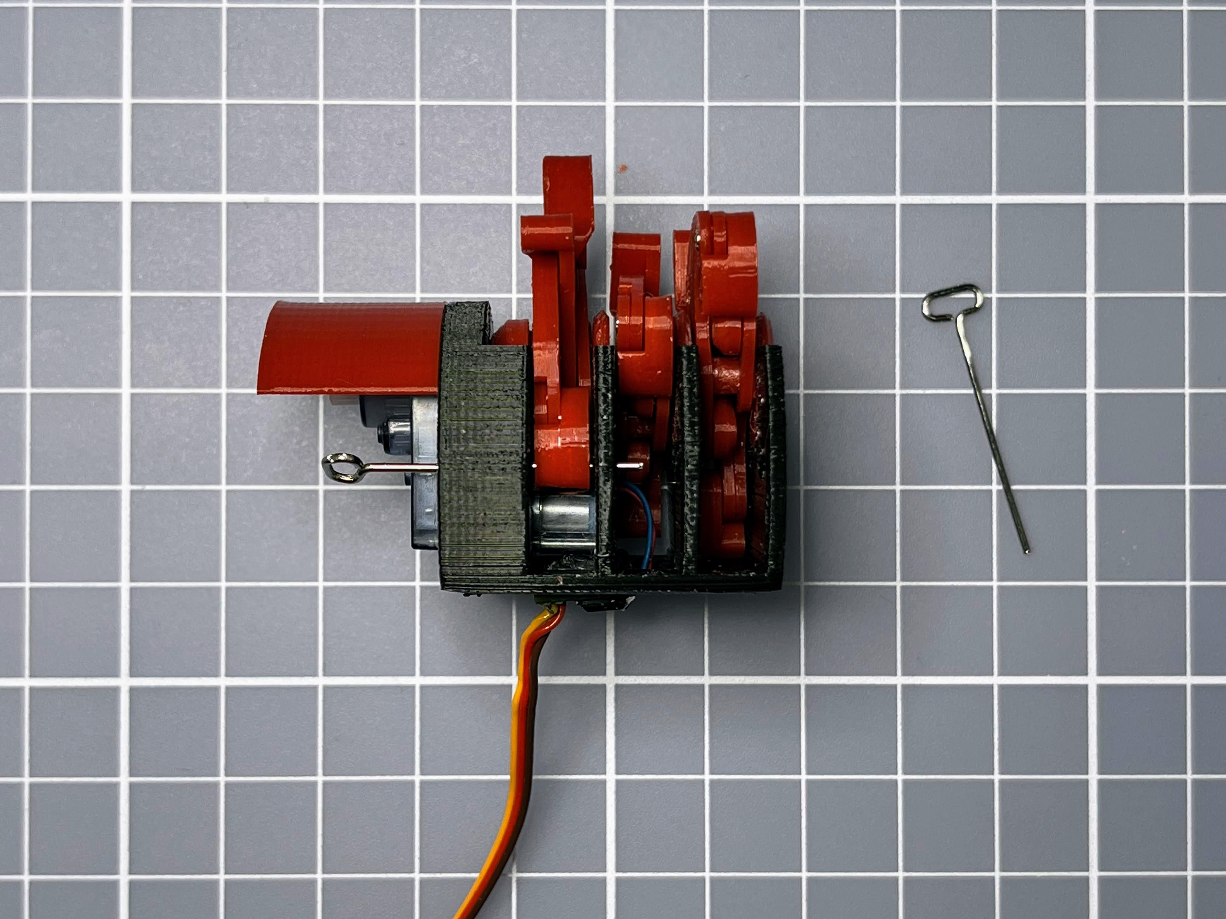
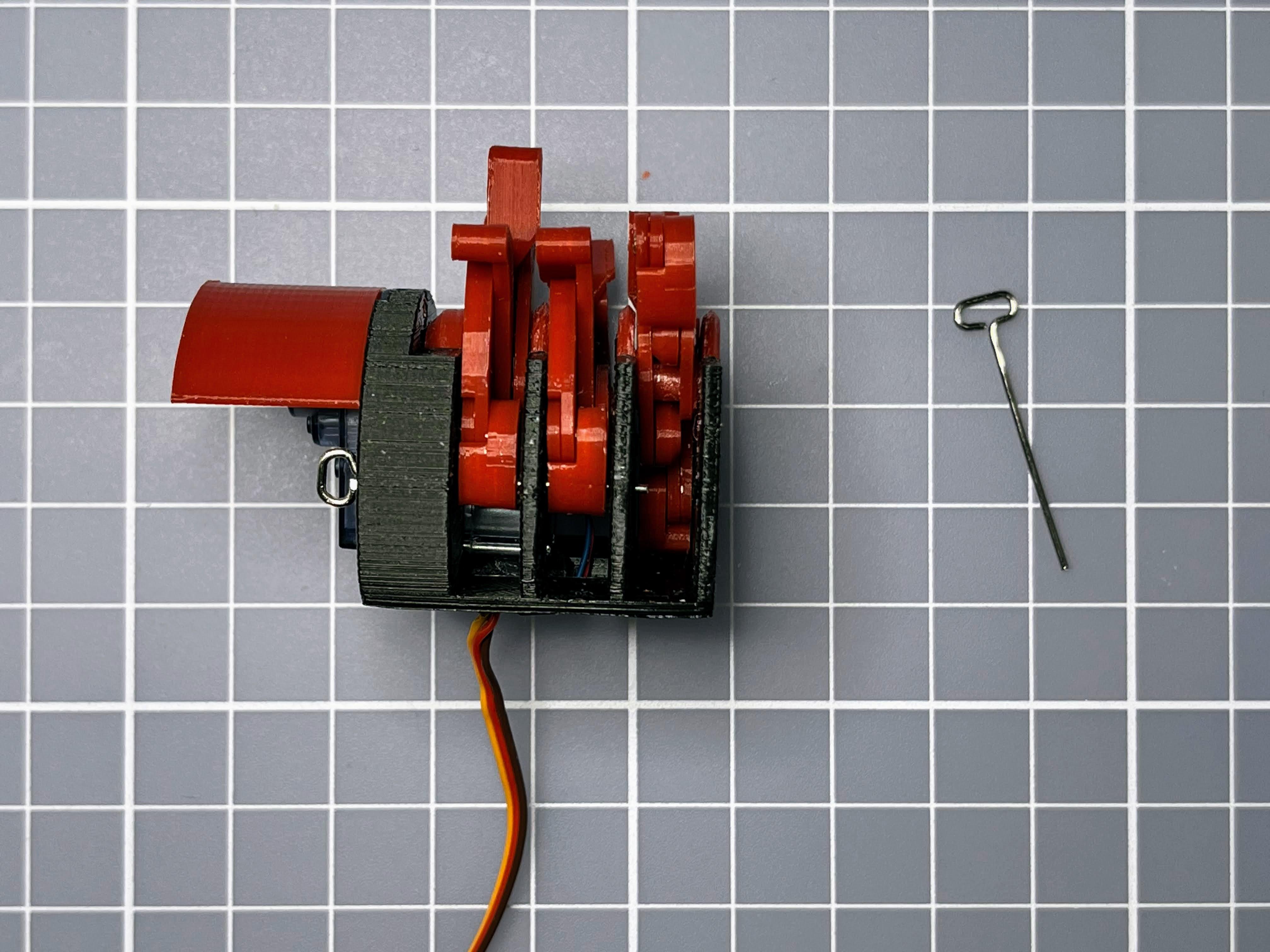
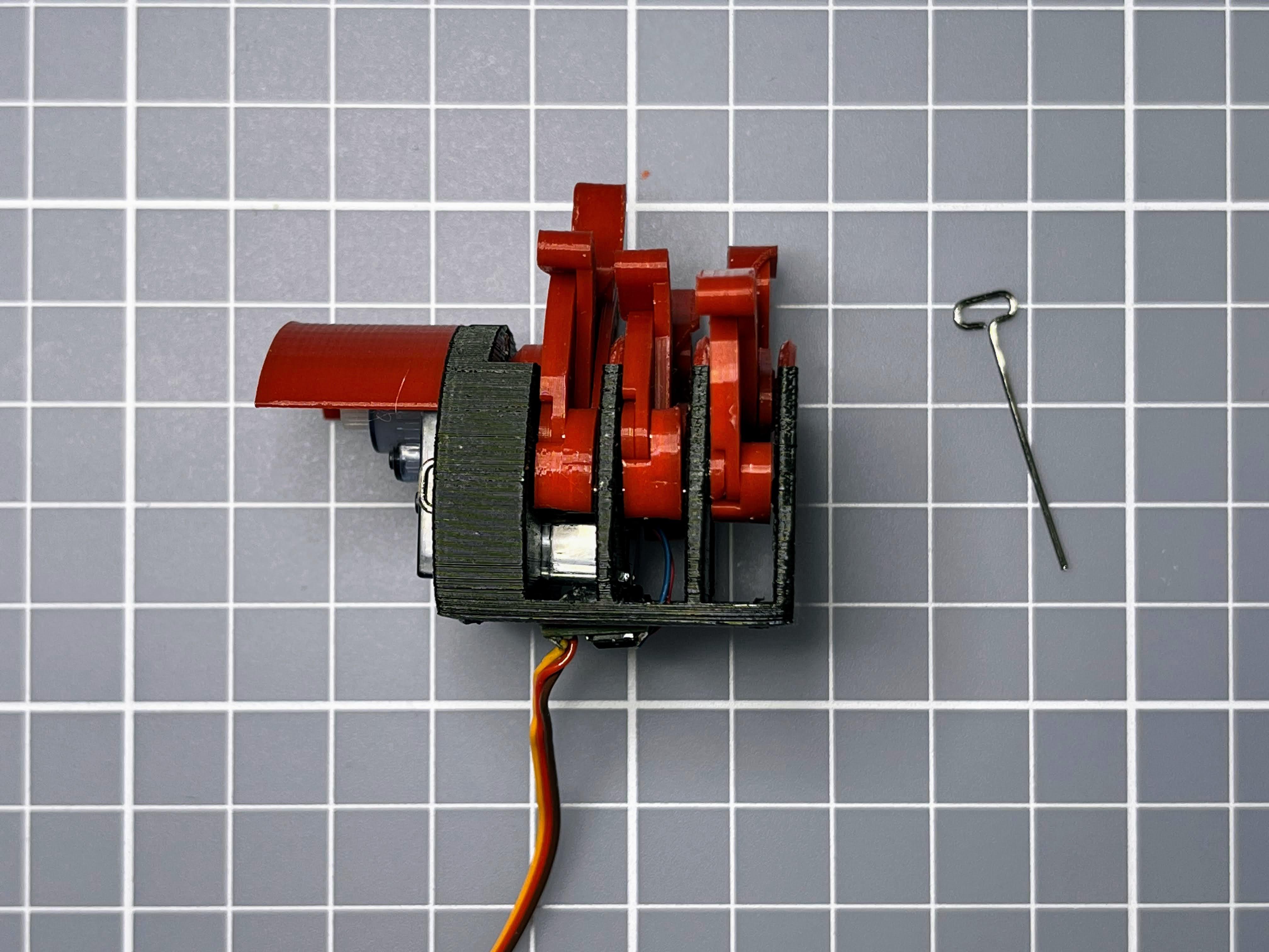
align the leg1 and let the paperclip axis pass through the body and all the leg1.
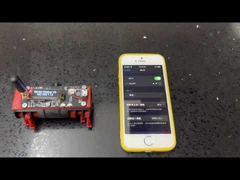
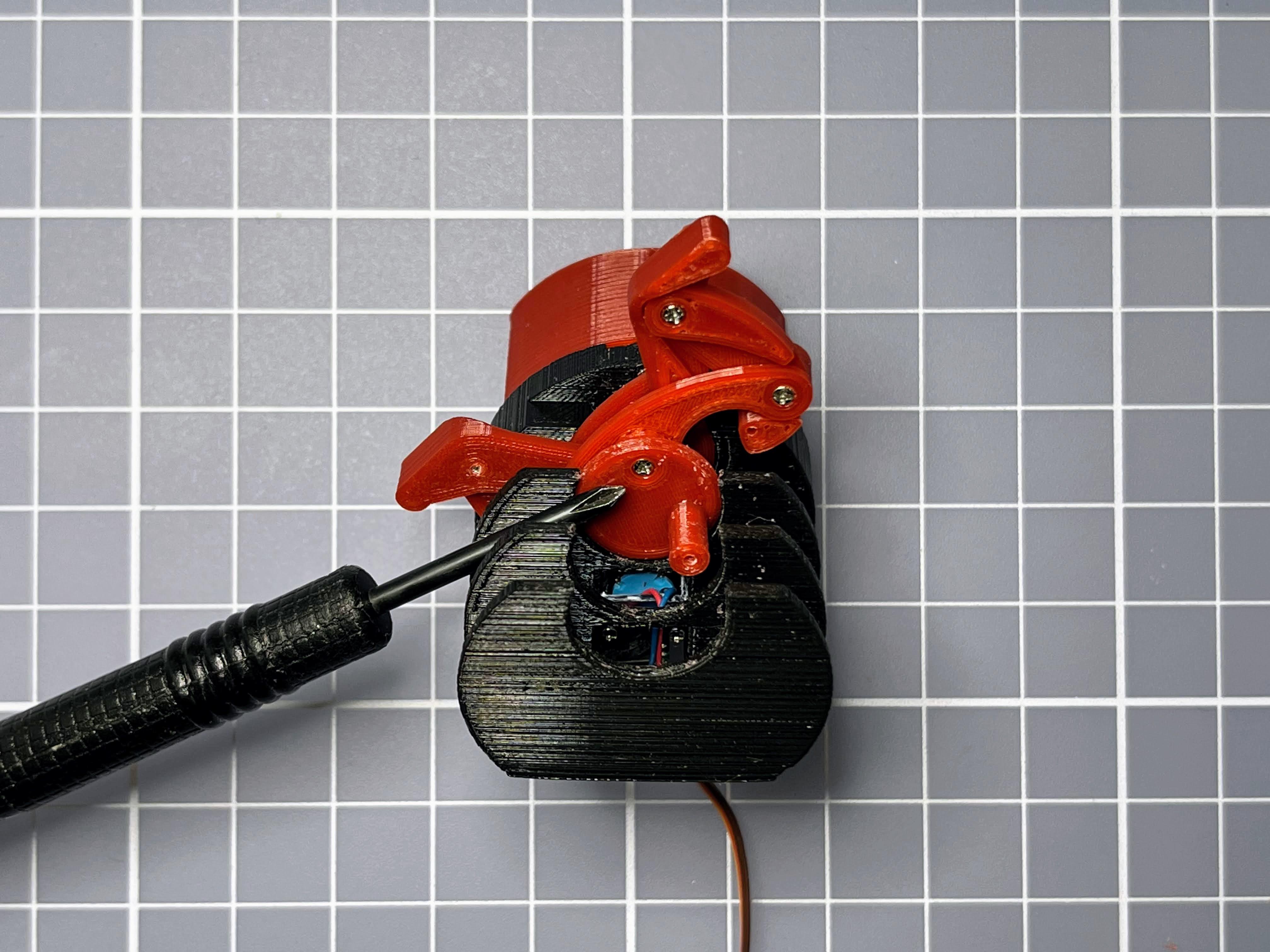
Test Run
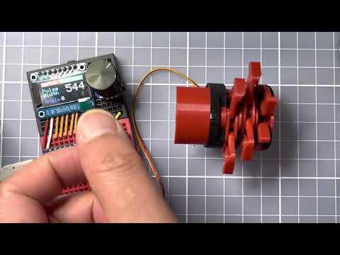
Use servo tester check all legs run smooth.
Install Another Side
Repeat steps 6-9 for the the side.
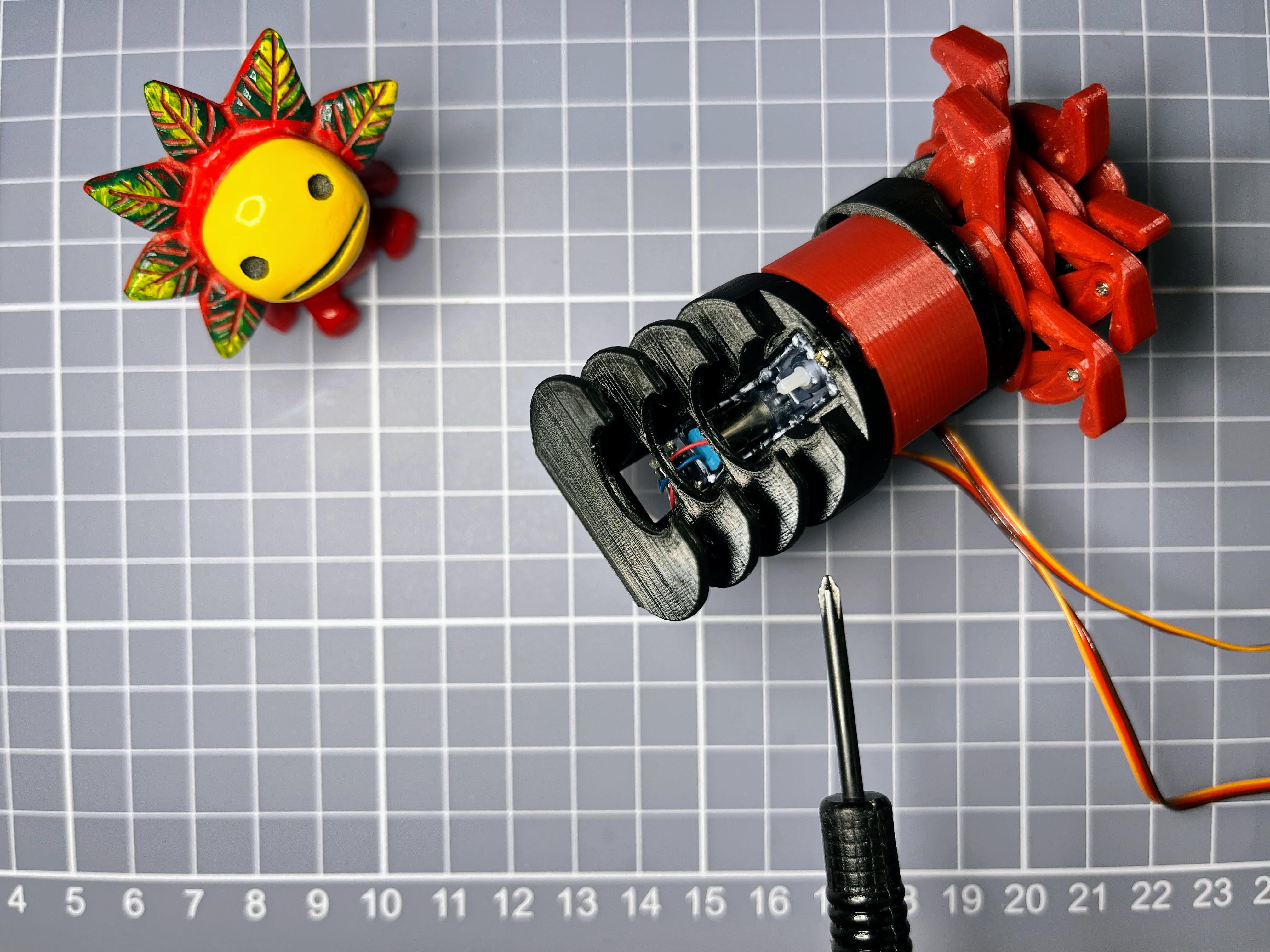
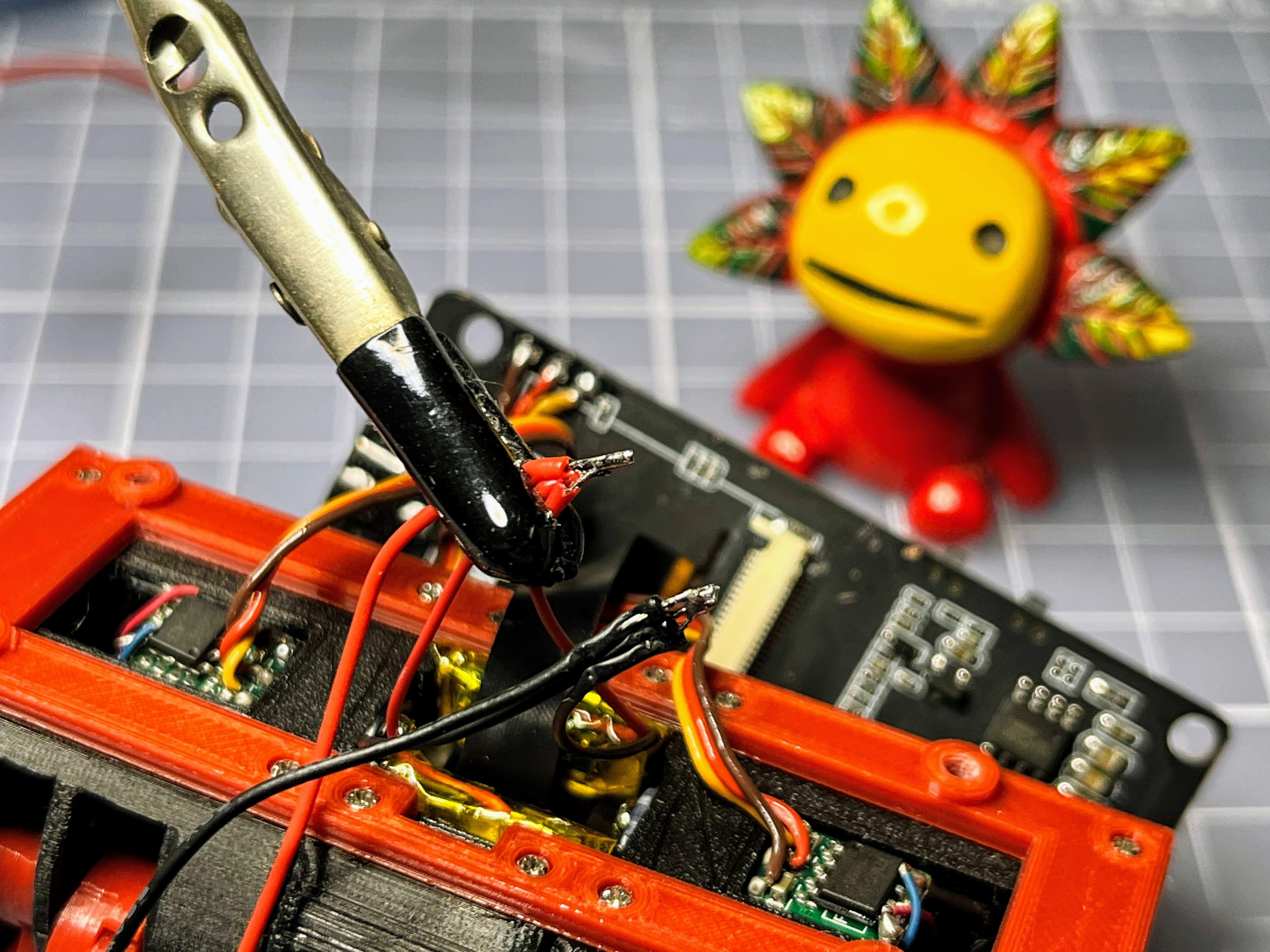
Connect 360 Servos
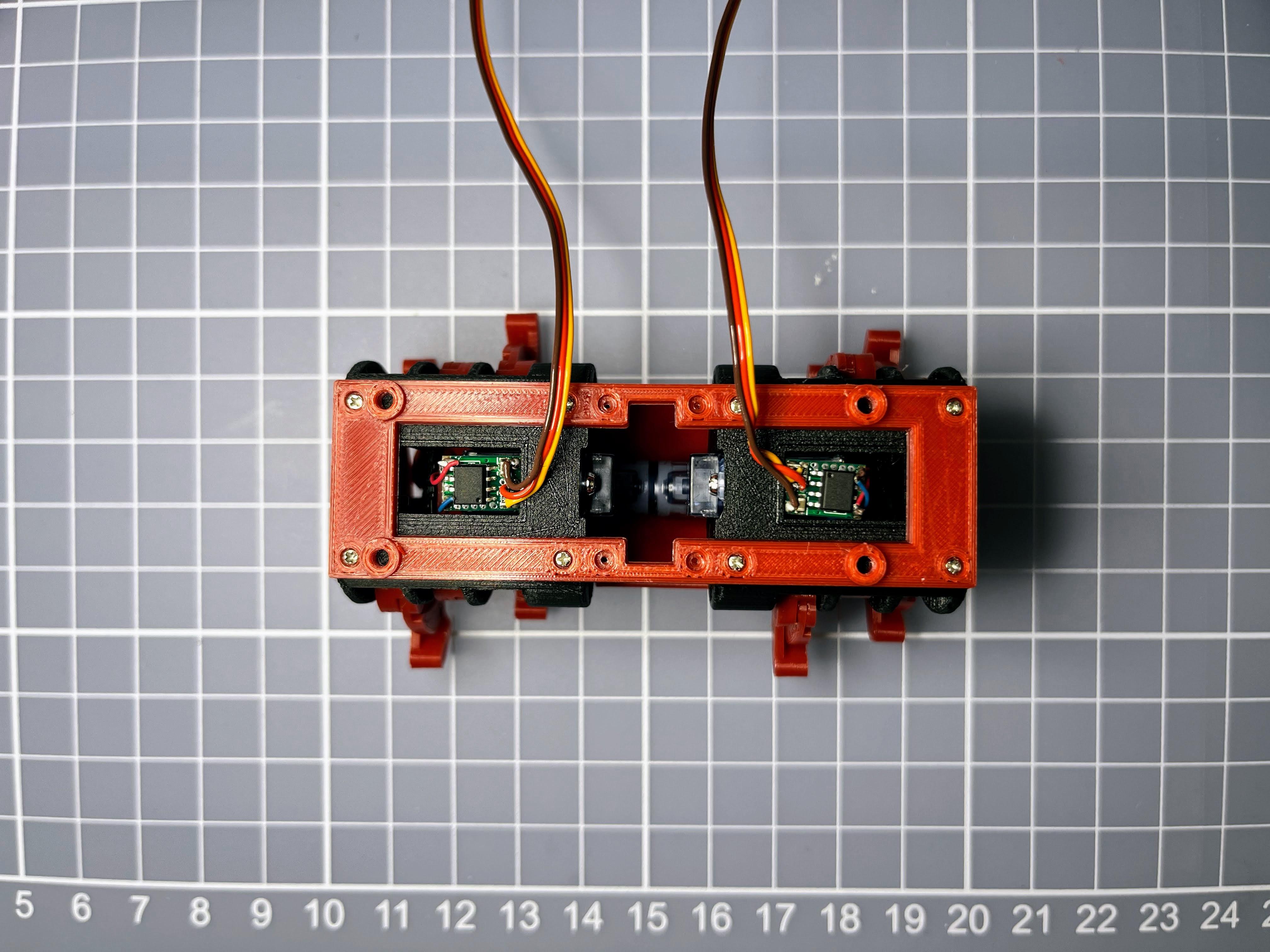
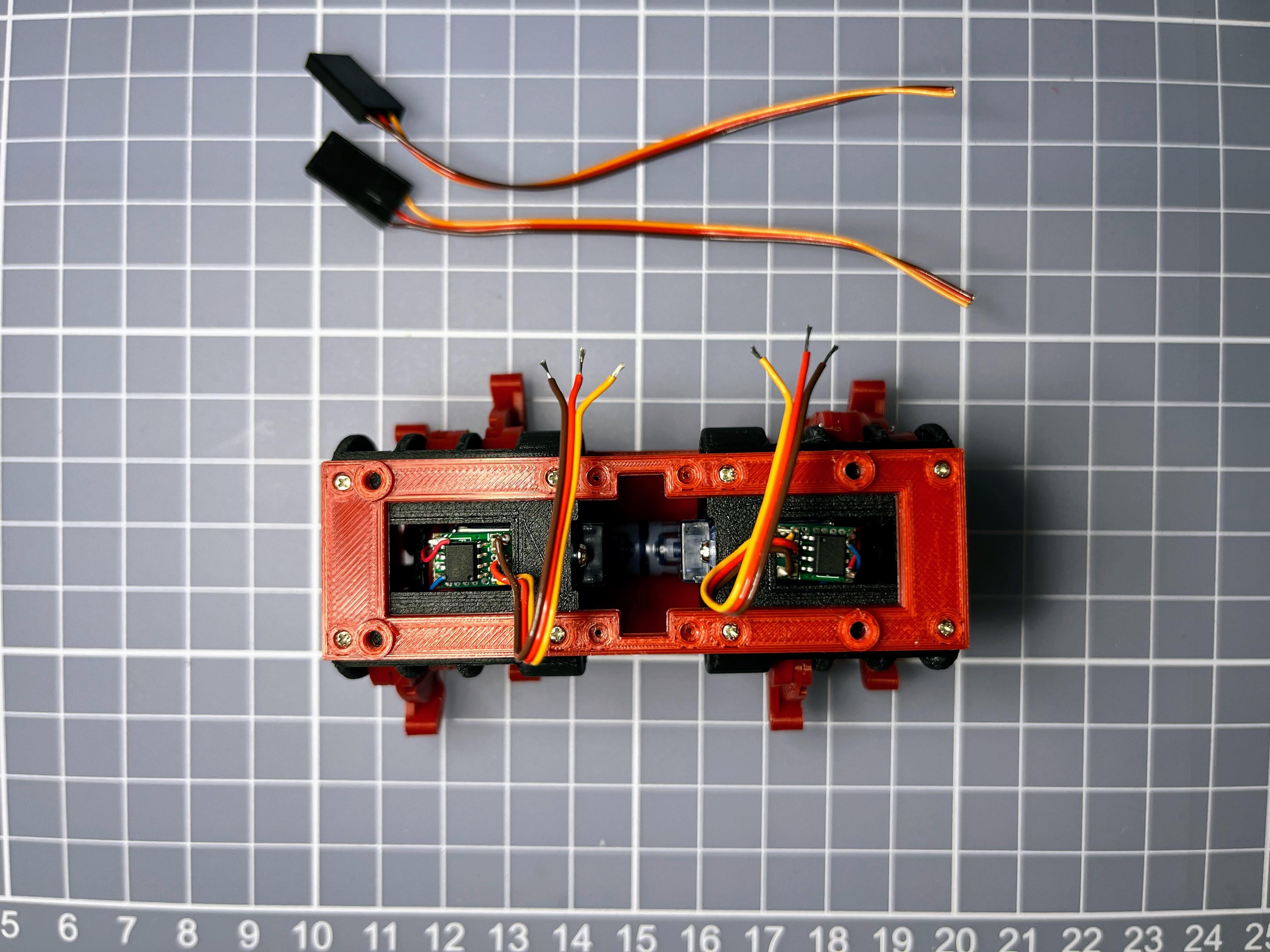
Screw up the T-Journal mount and body with 8 screws.
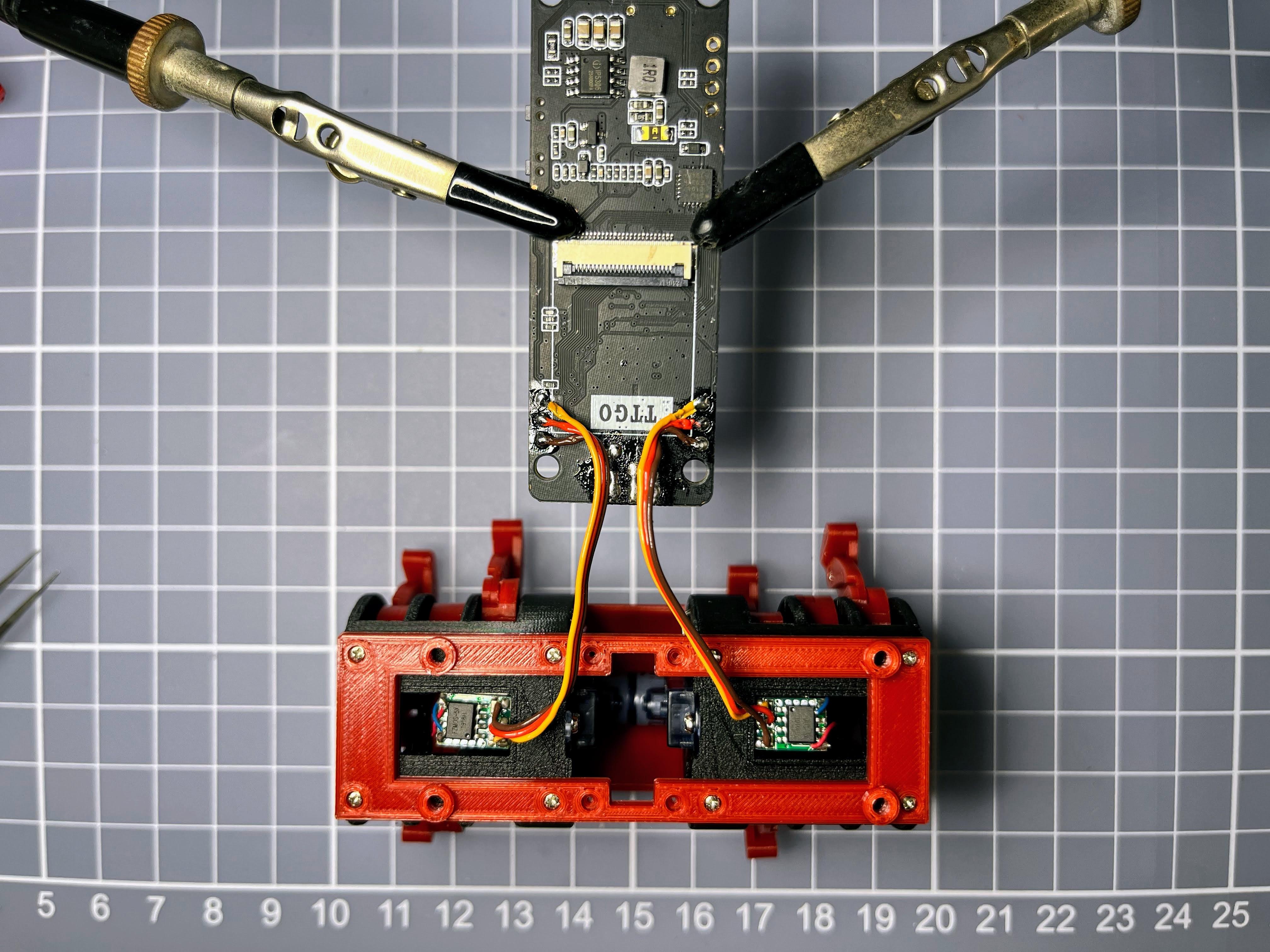
Cut the 360 servos wire and soldering to the TTGO T-Journal. Left side connect to GPIO 2, 3V3 and GND; Right side connect to GPIO 4, 3V3 and GND.
Install Battery
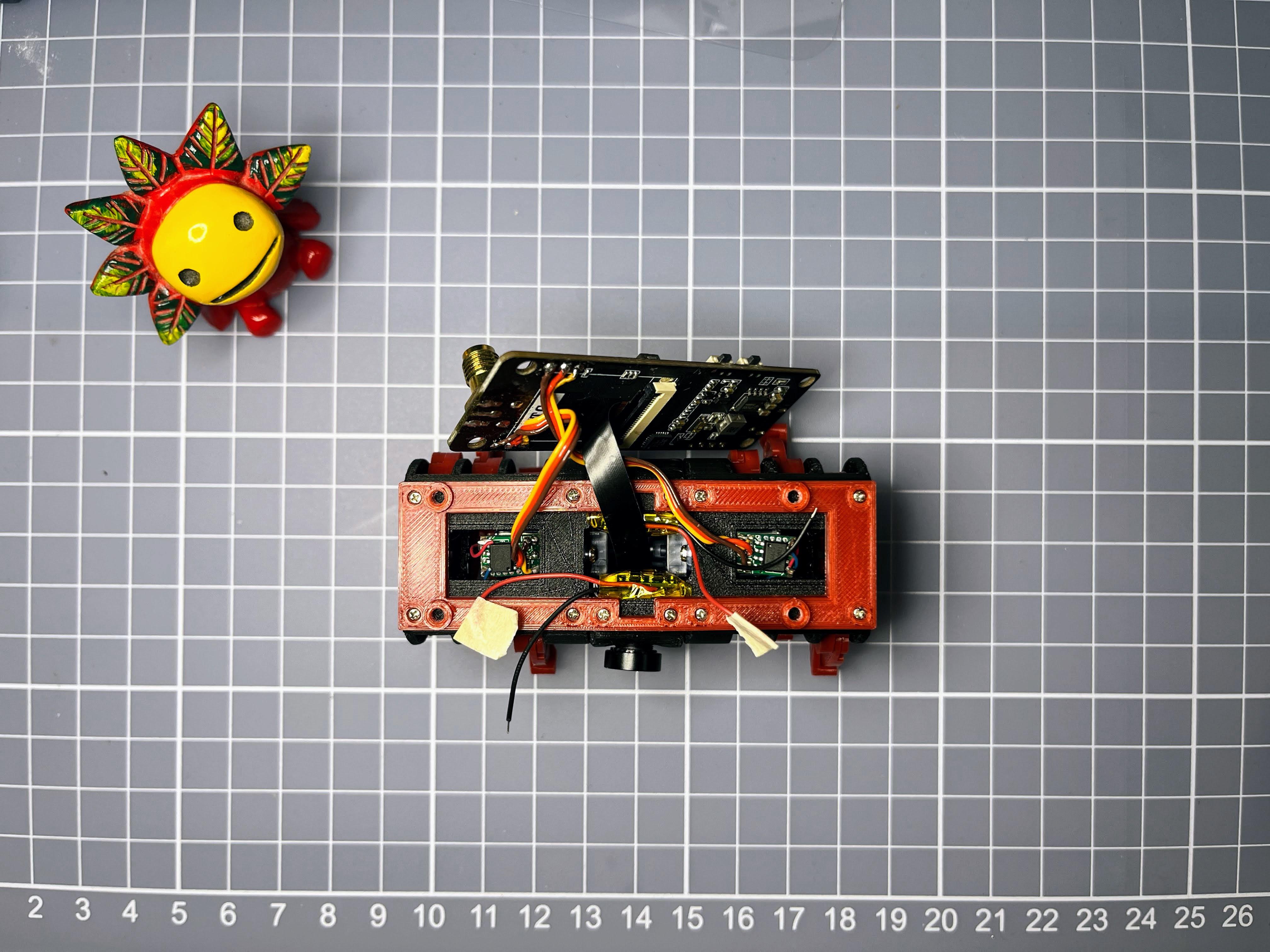
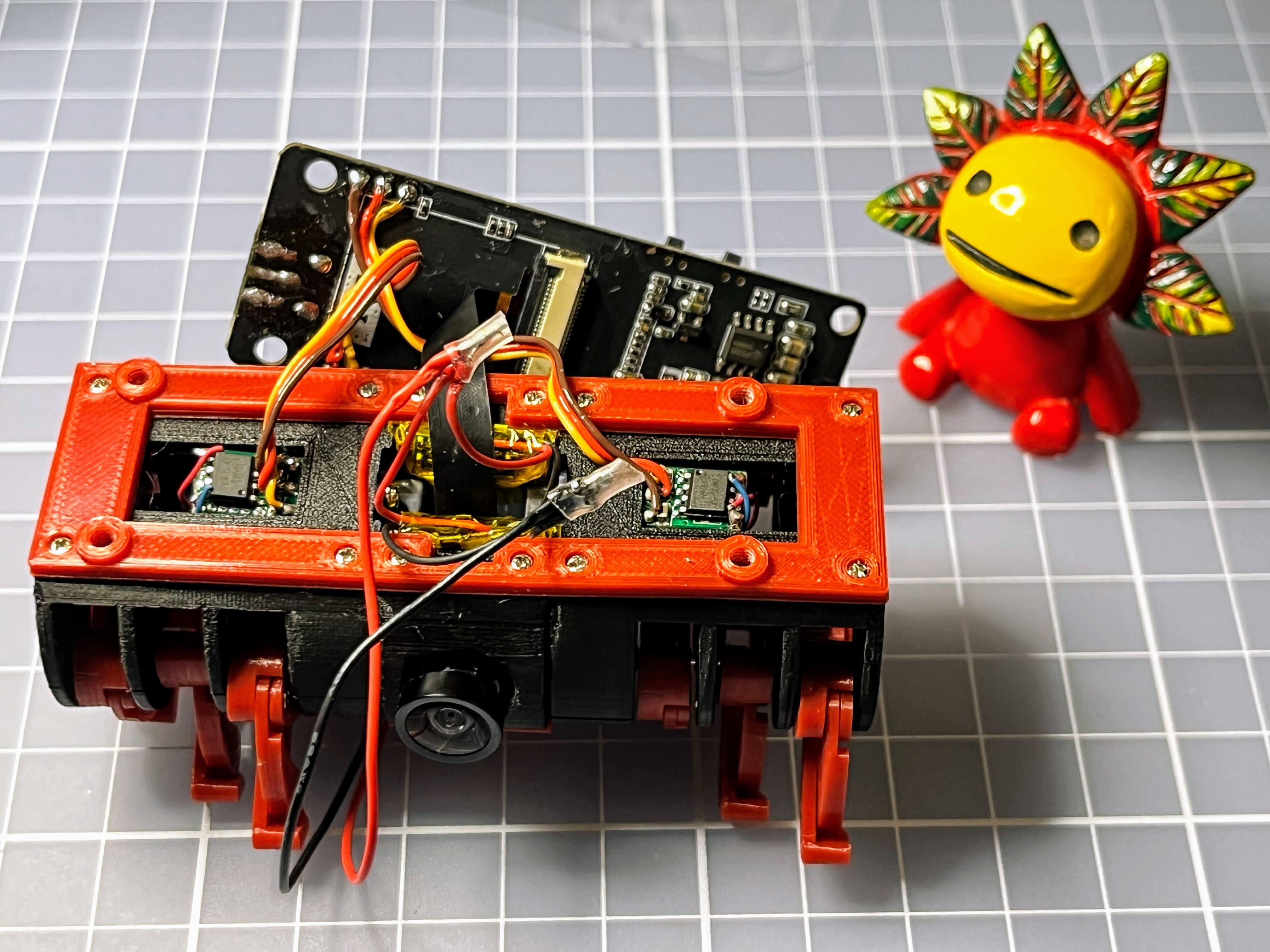
- Squeeze 2 Lipo batteries into the robot body front and back
- Screw up T-Journal mount, front and back with 4 screws
- Soldering 2 of them together in parallel connection to get a larger battery
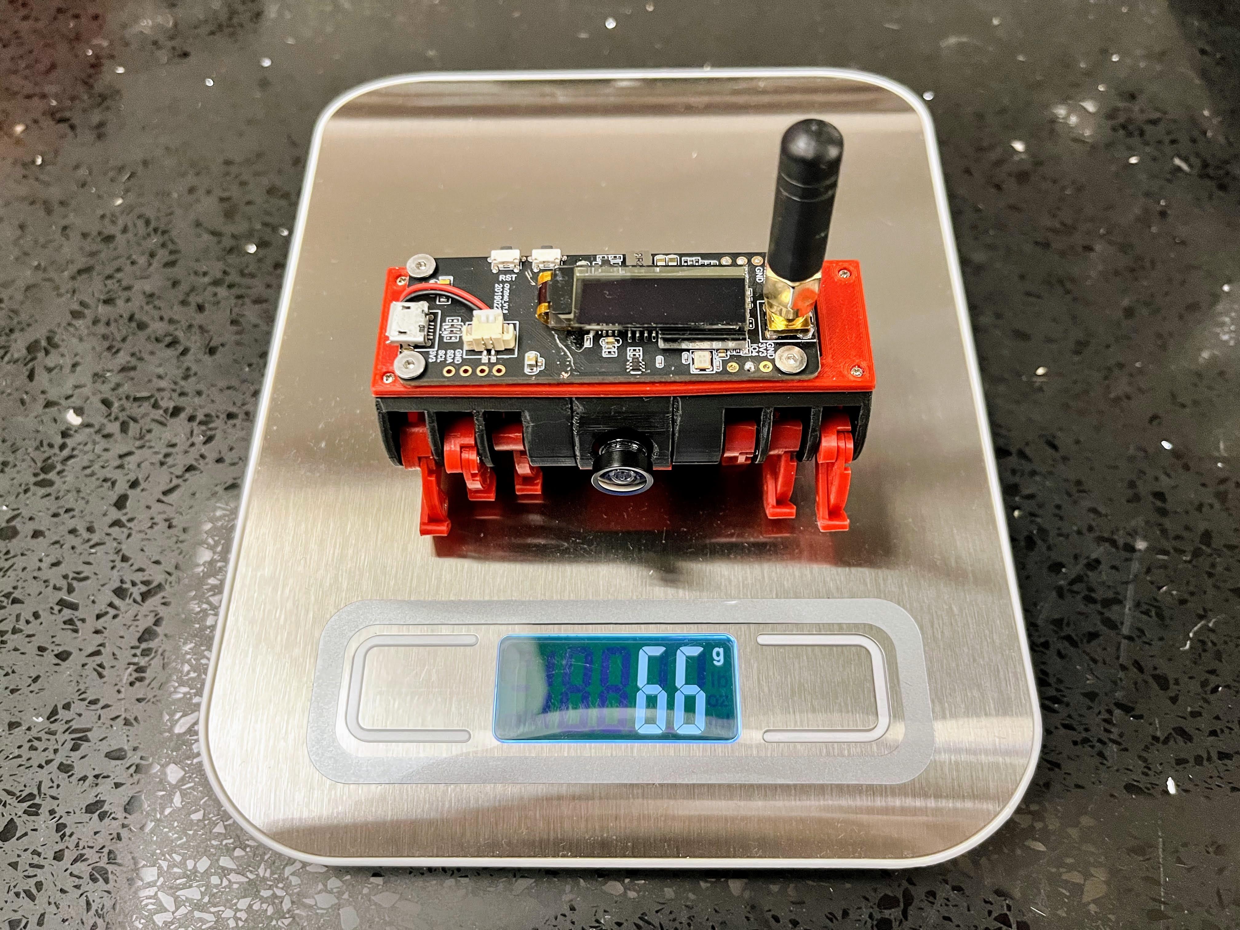
Weight
Program
This instructables mainly describe the new version hardware assembly. Please refer to my previous instructables for the programming steps.
Note:
Please uncomment below line in camera_pins.h for this version:
#define CAMERA_MODEL_TTGO_T_JOURNAL_ROBOT
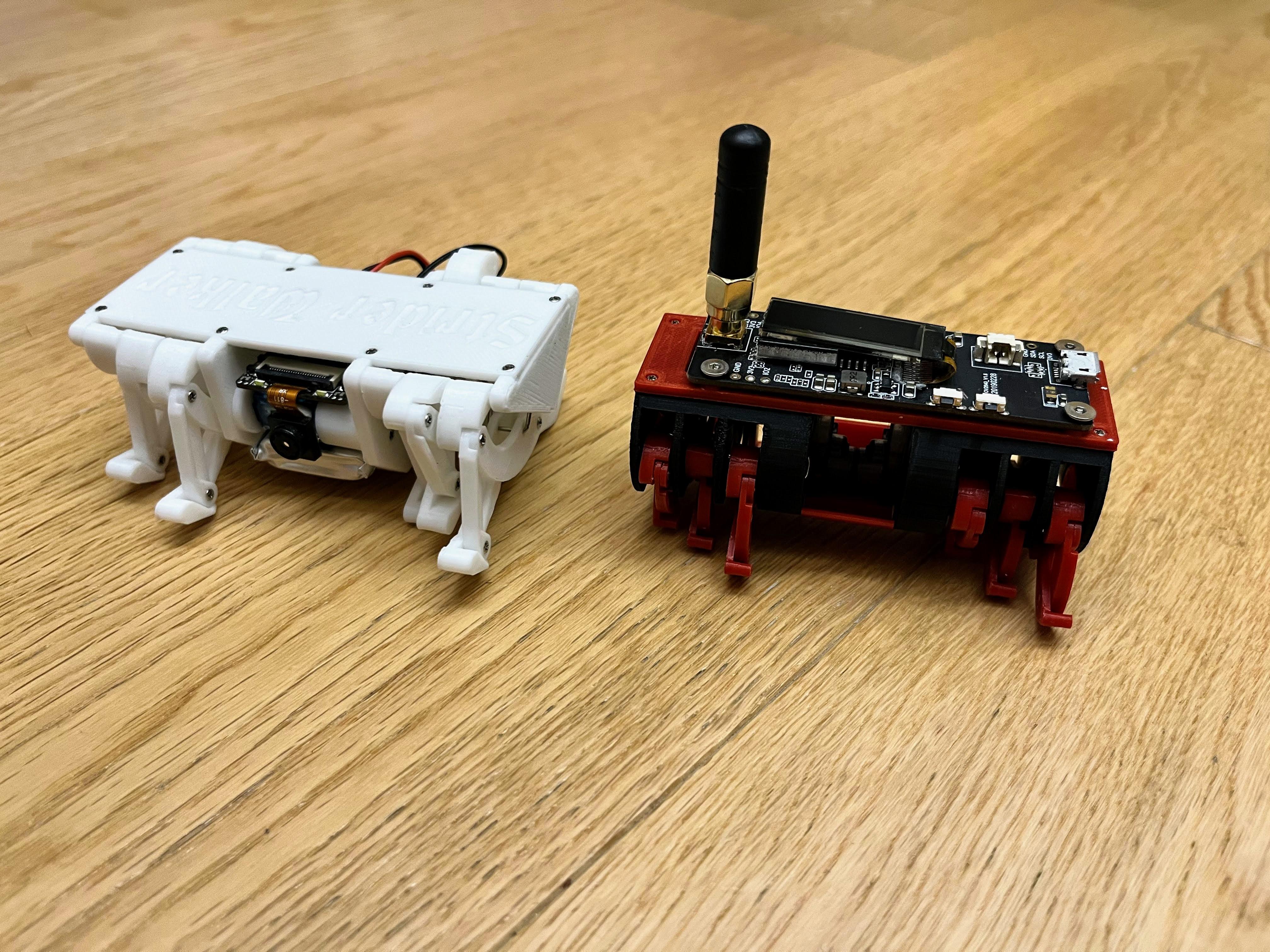
V2 Vs V6