Store Your Headphones in Style
by daapplab in Living > Decorating
1073 Views, 5 Favorites, 0 Comments
Store Your Headphones in Style
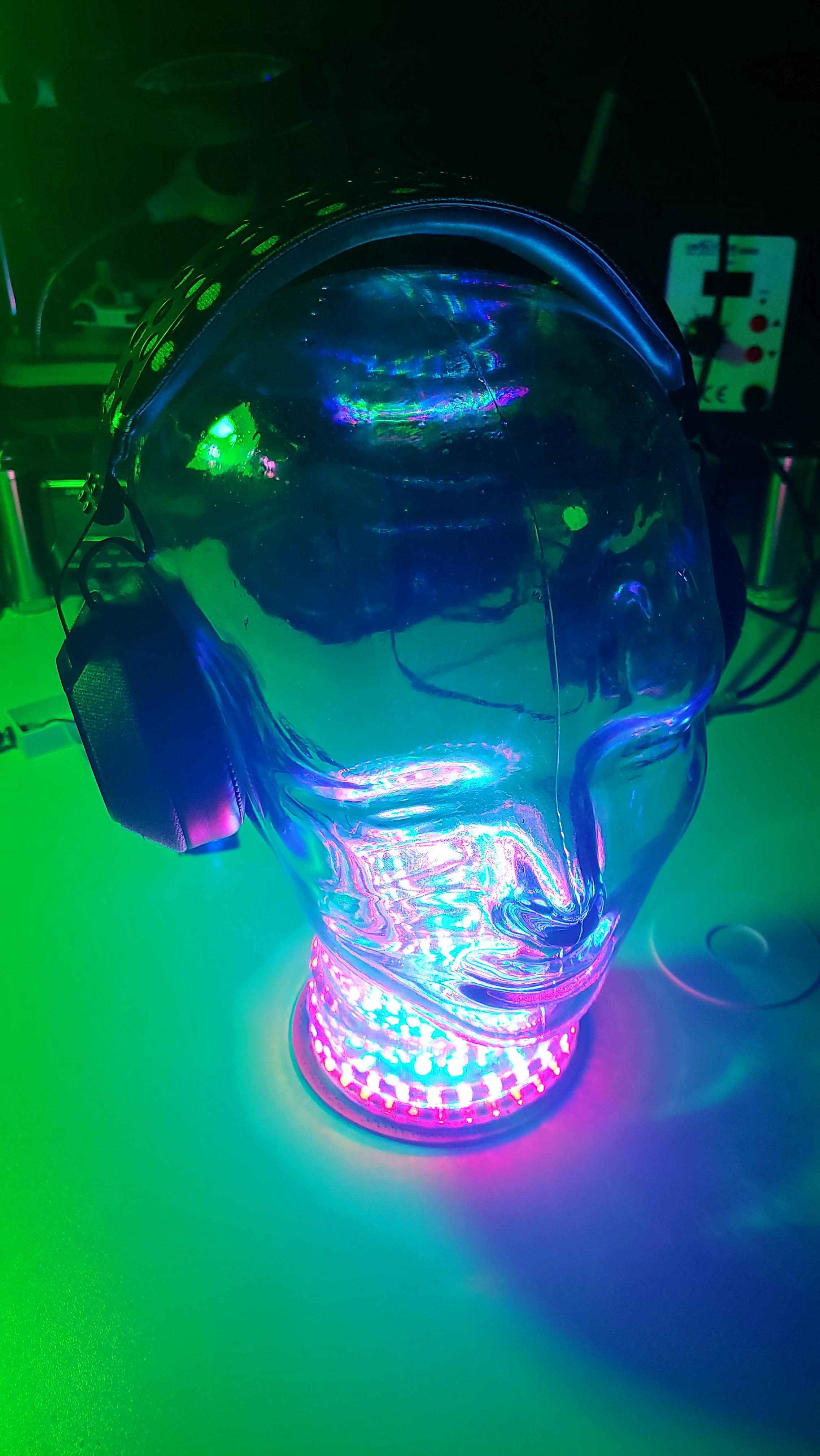
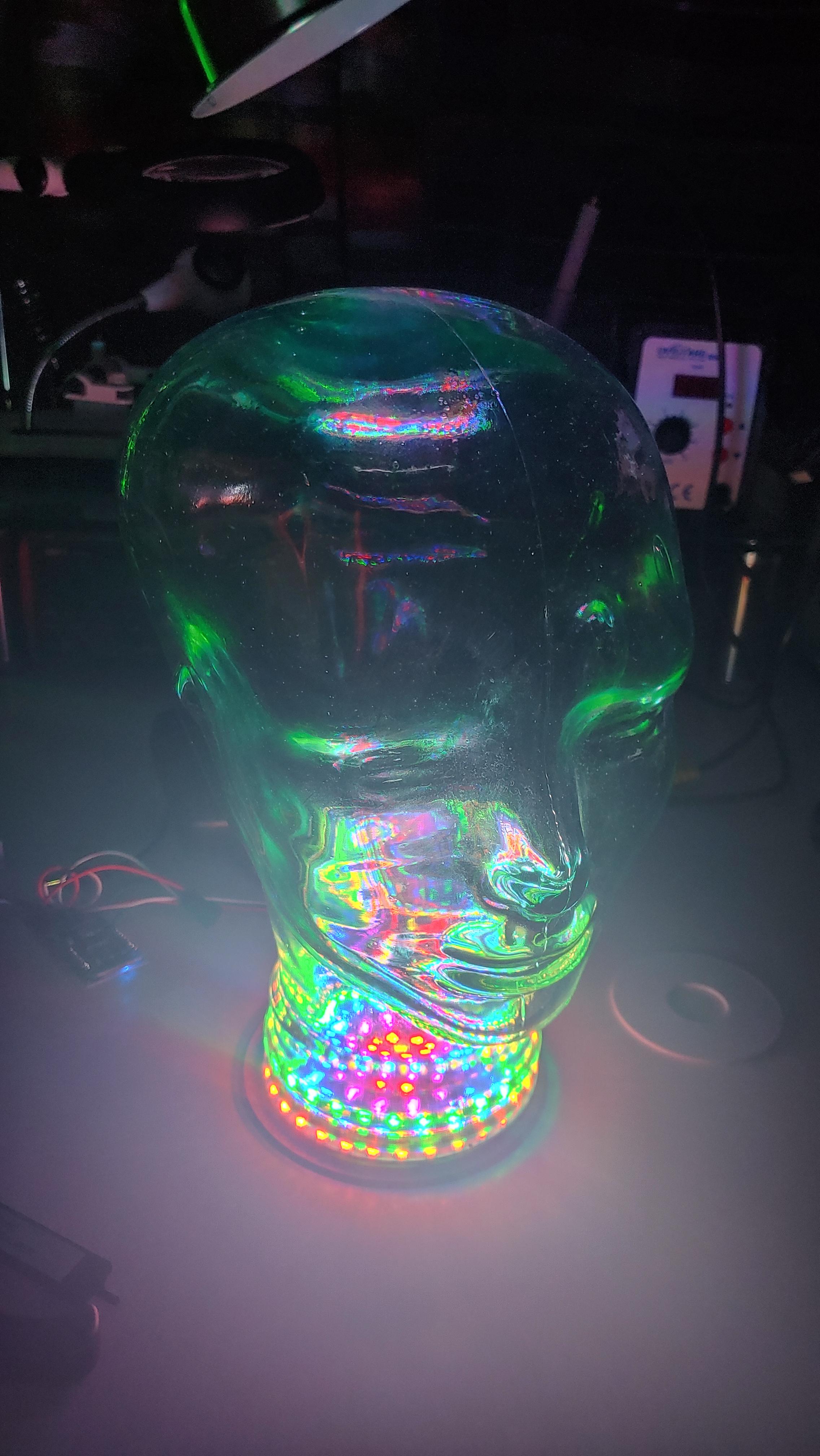
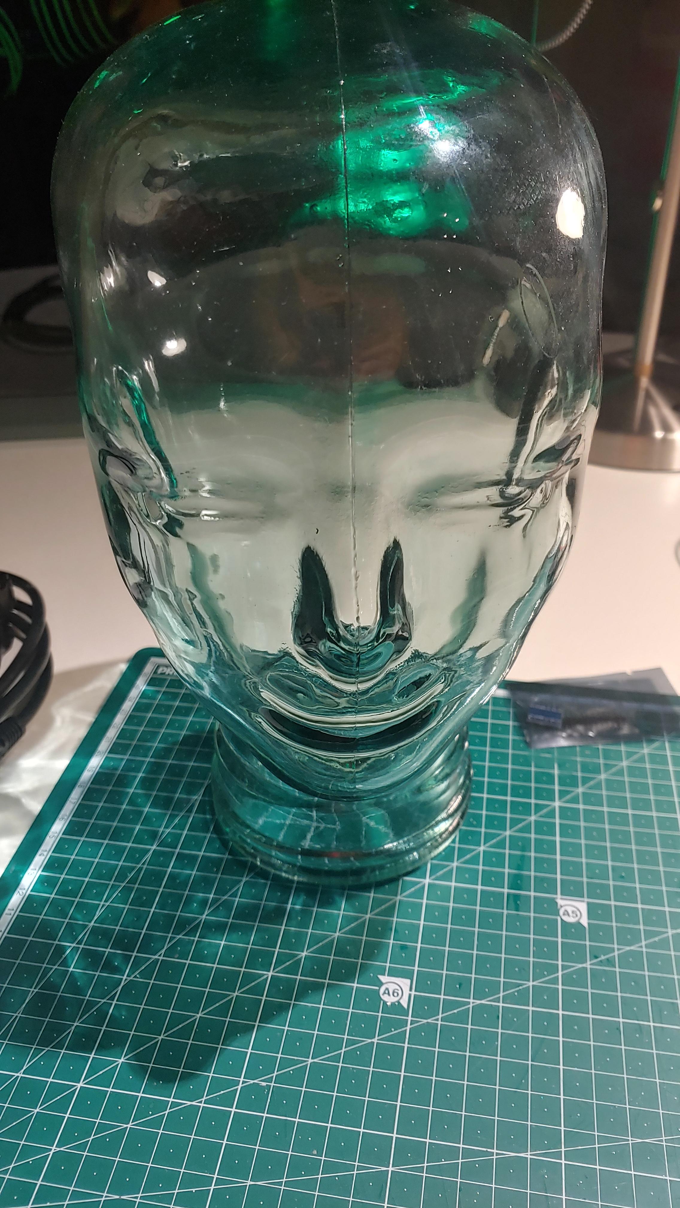
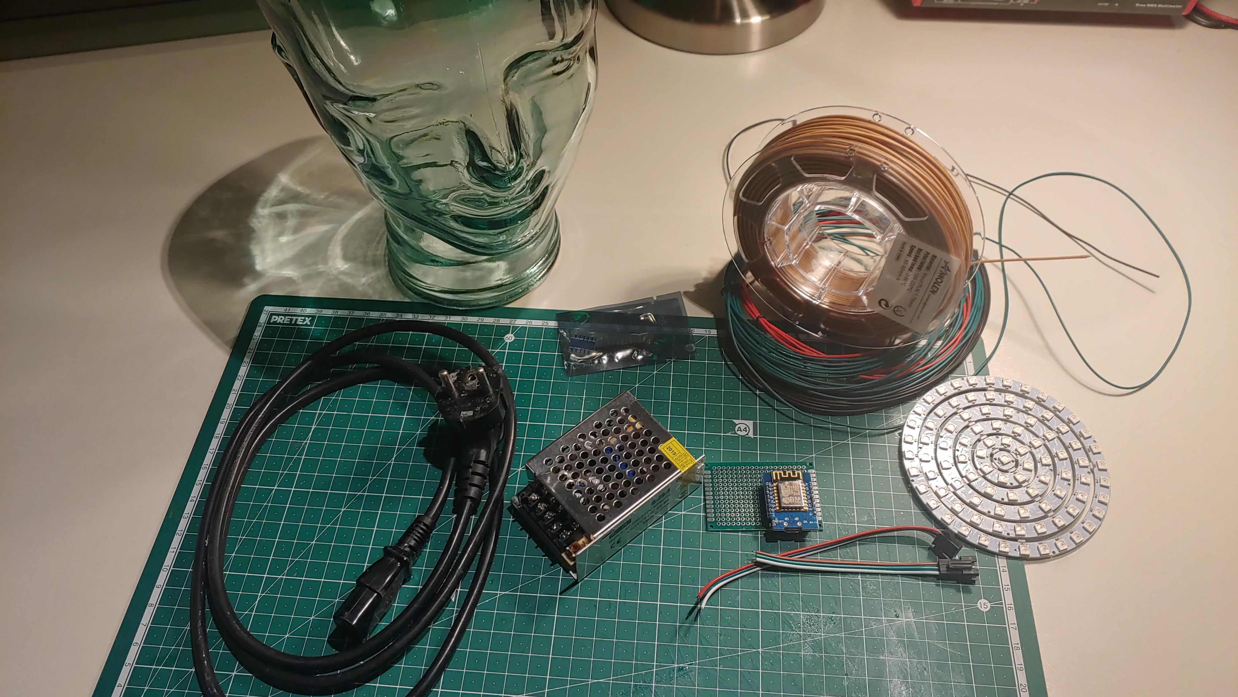

I really love my different headphones. However, when you have just two ears like me you will likely only use one pair of them at most at a time. Therefore I want to show you in this instructable how you can store all your unused headphones in style.
I will show you how you can use a glass headphone stand, some LED's and a 3D printer to create an awesome illuminated Headphone throne (the glowing effect is way better in reality than on pictures)!
So, let's ago!
Supplies
Parts:
- Glass Head
- Circular LED's (6 rings or 110mm)
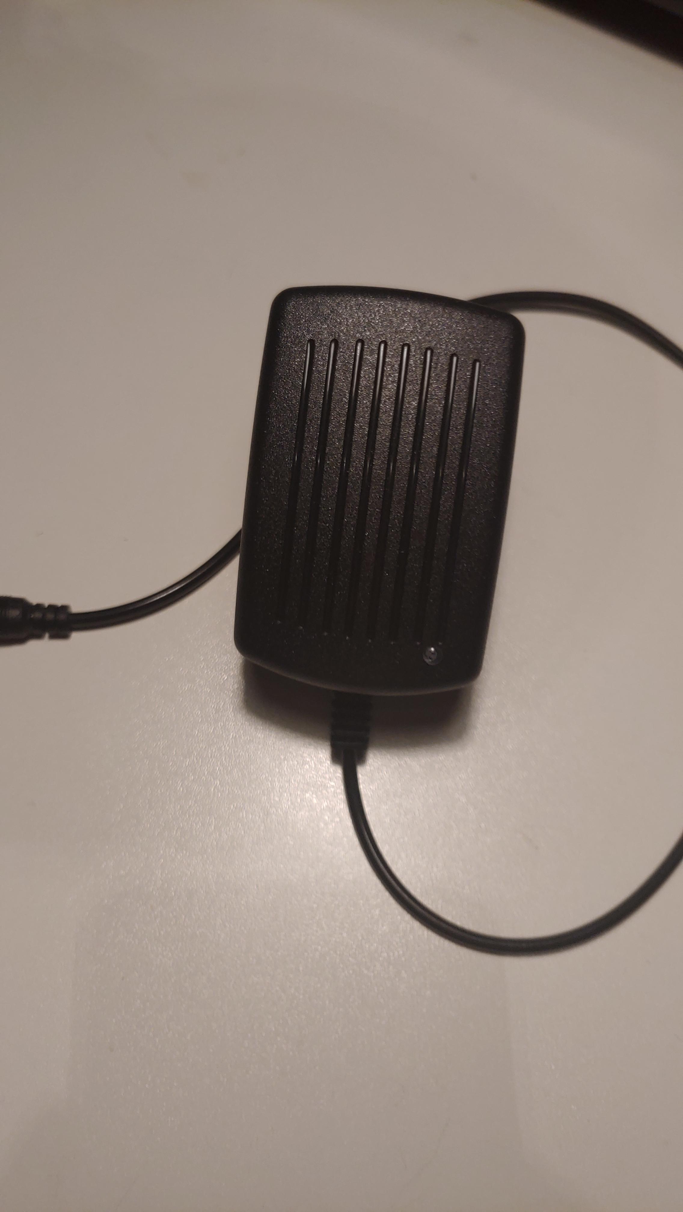
- PSU (5V 4A)
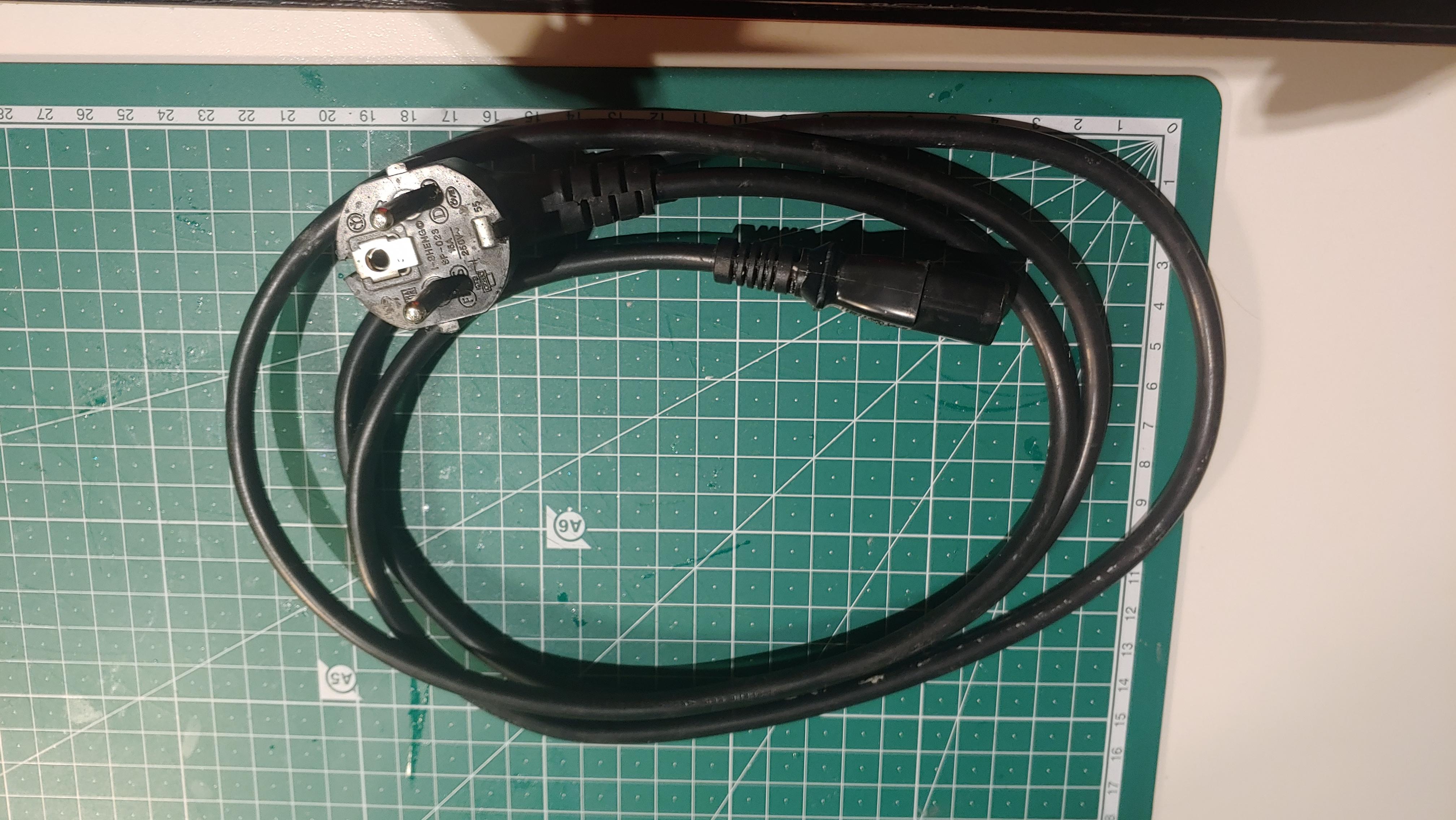
- Cables
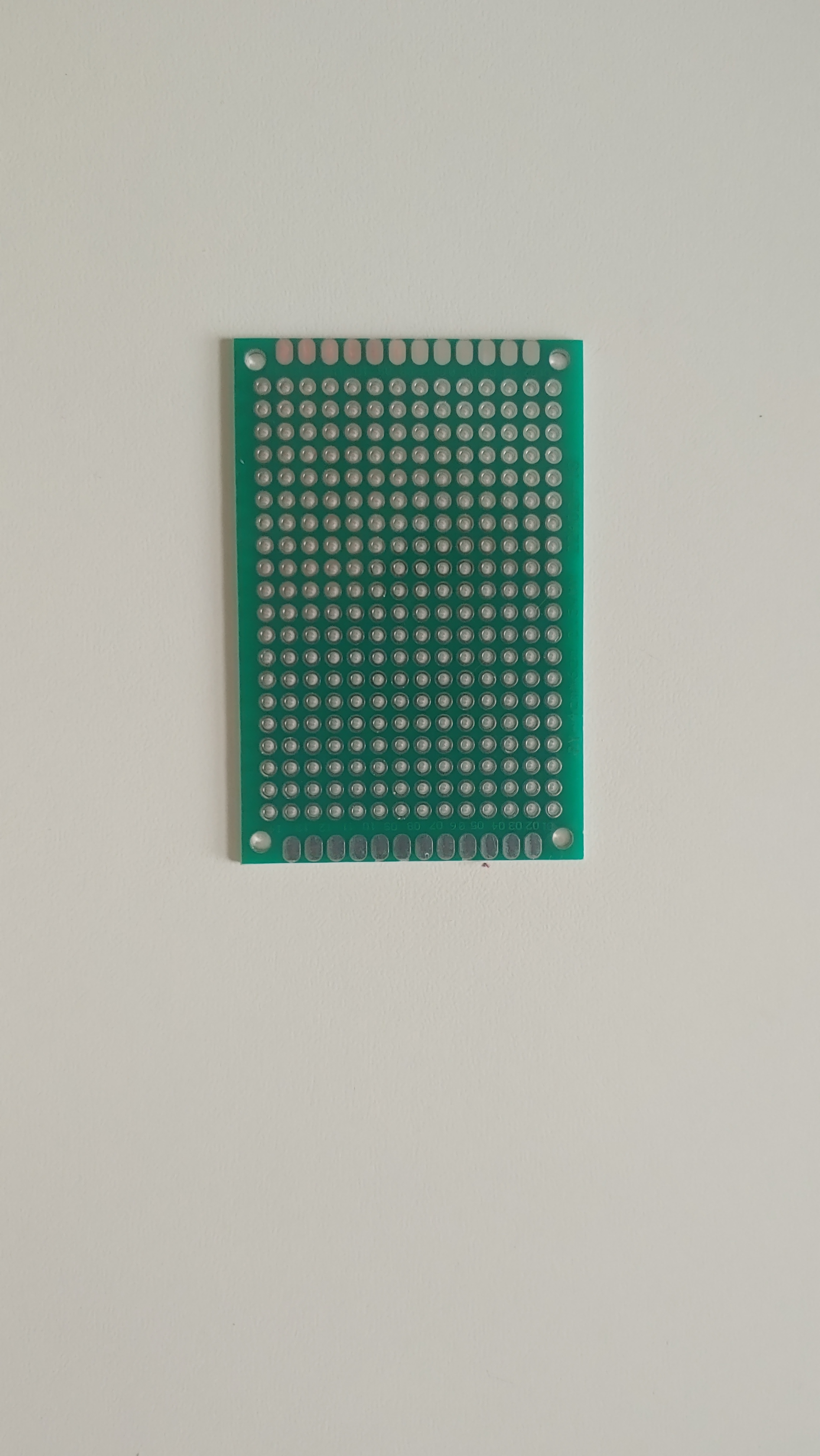
- Prototype PCB
- Filament
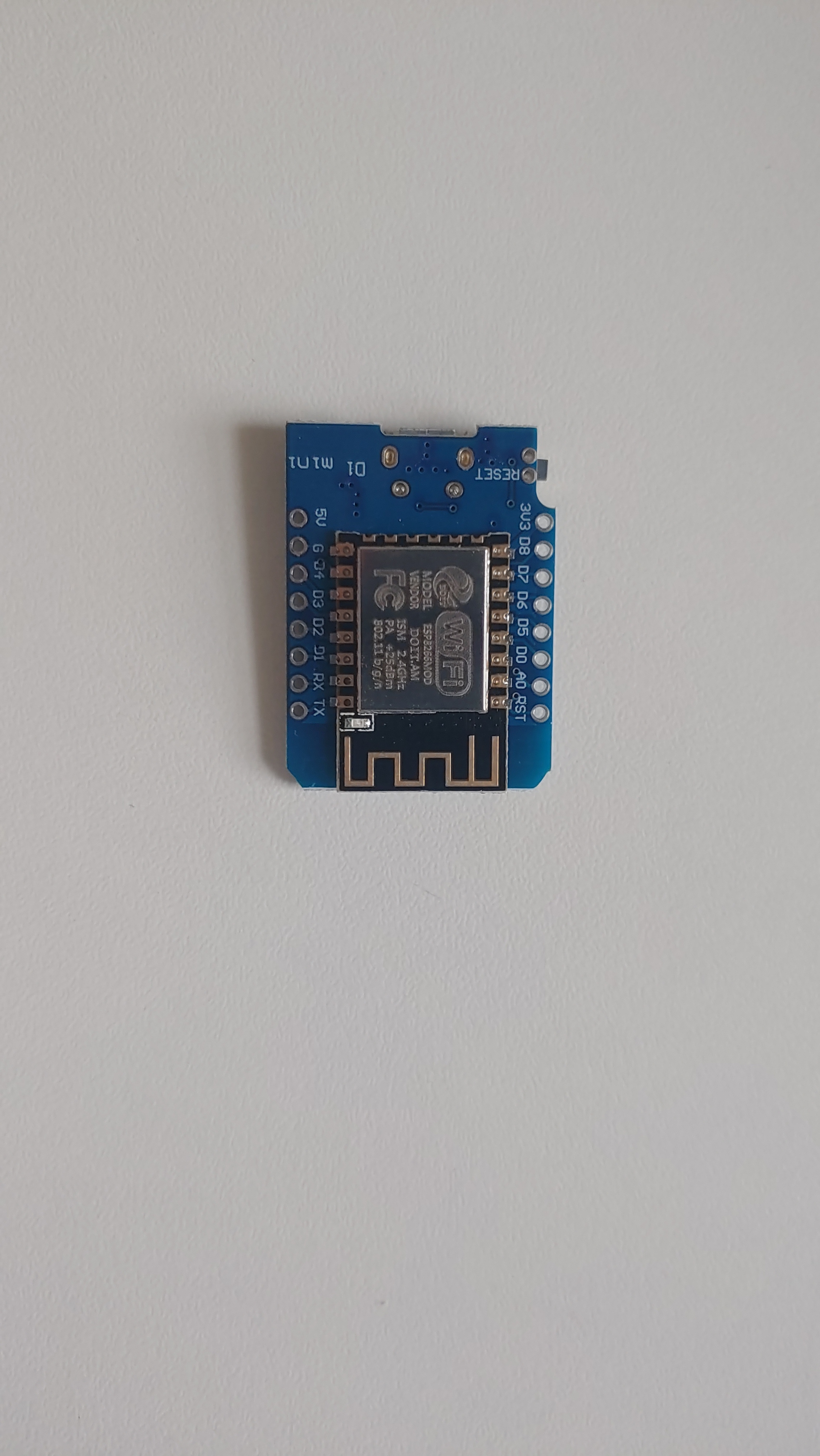
- ESP8266 (D1 mini)
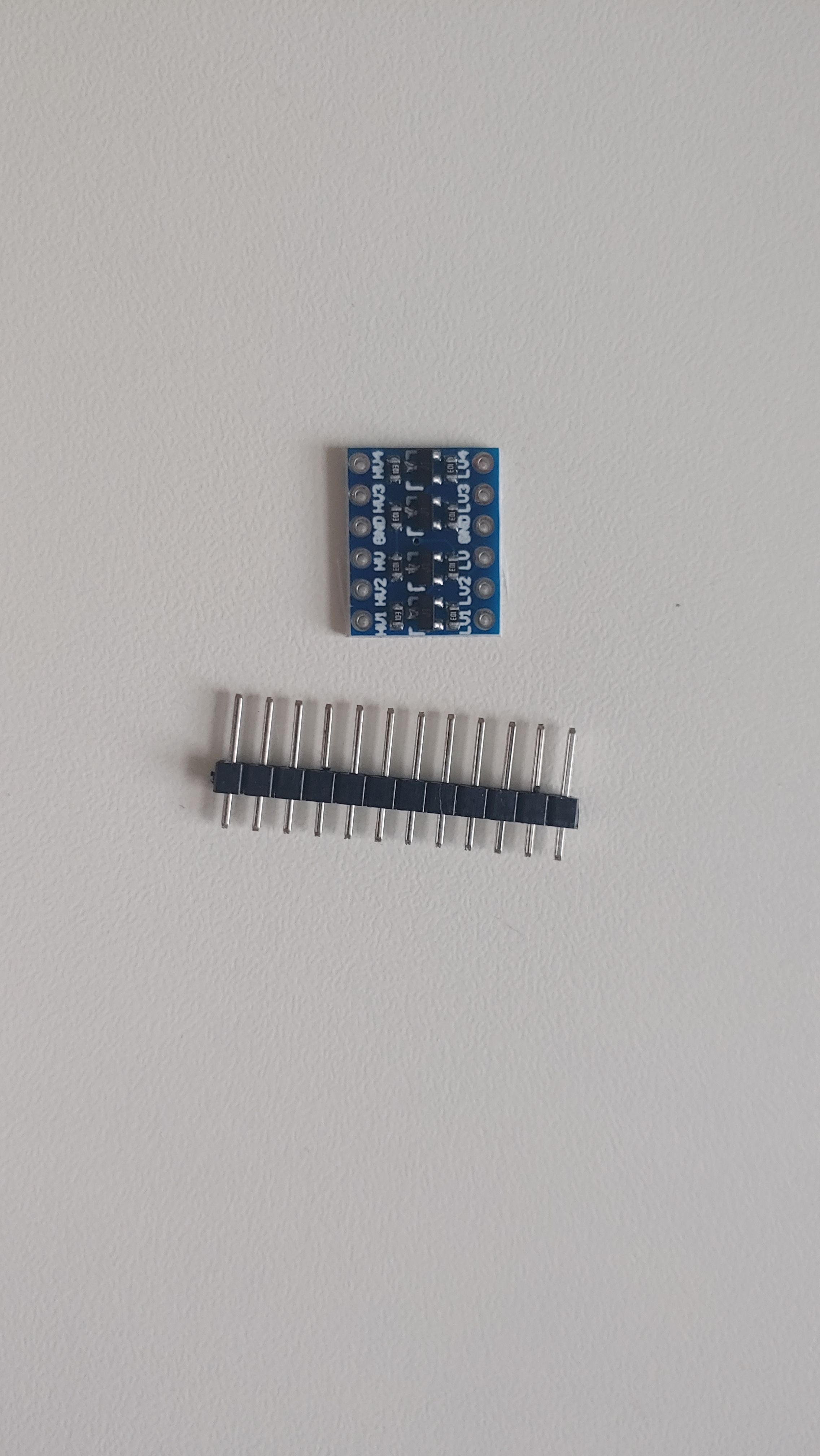
- Voltage Level Converter
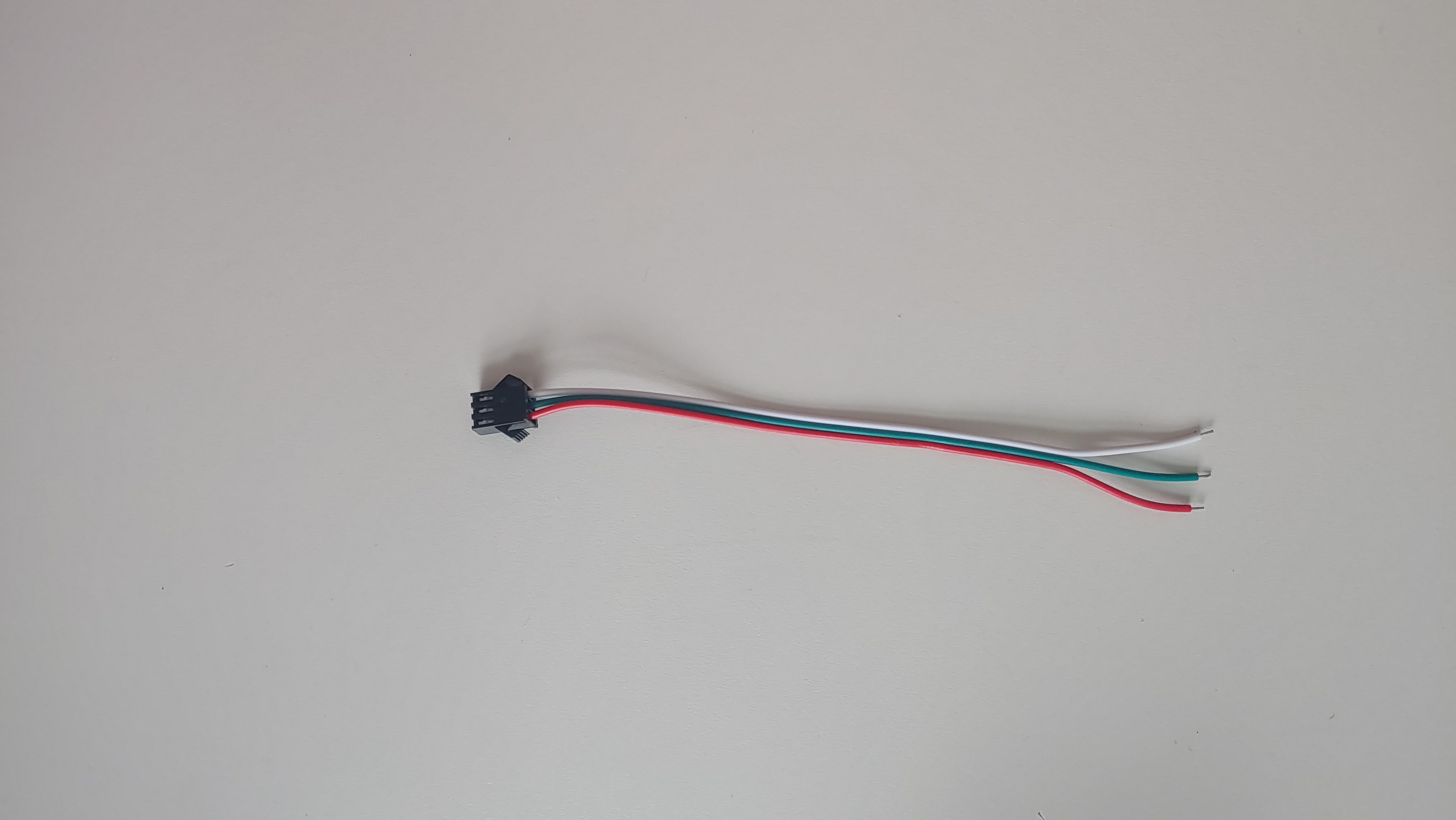
- 3-pin LED connector (male and female)
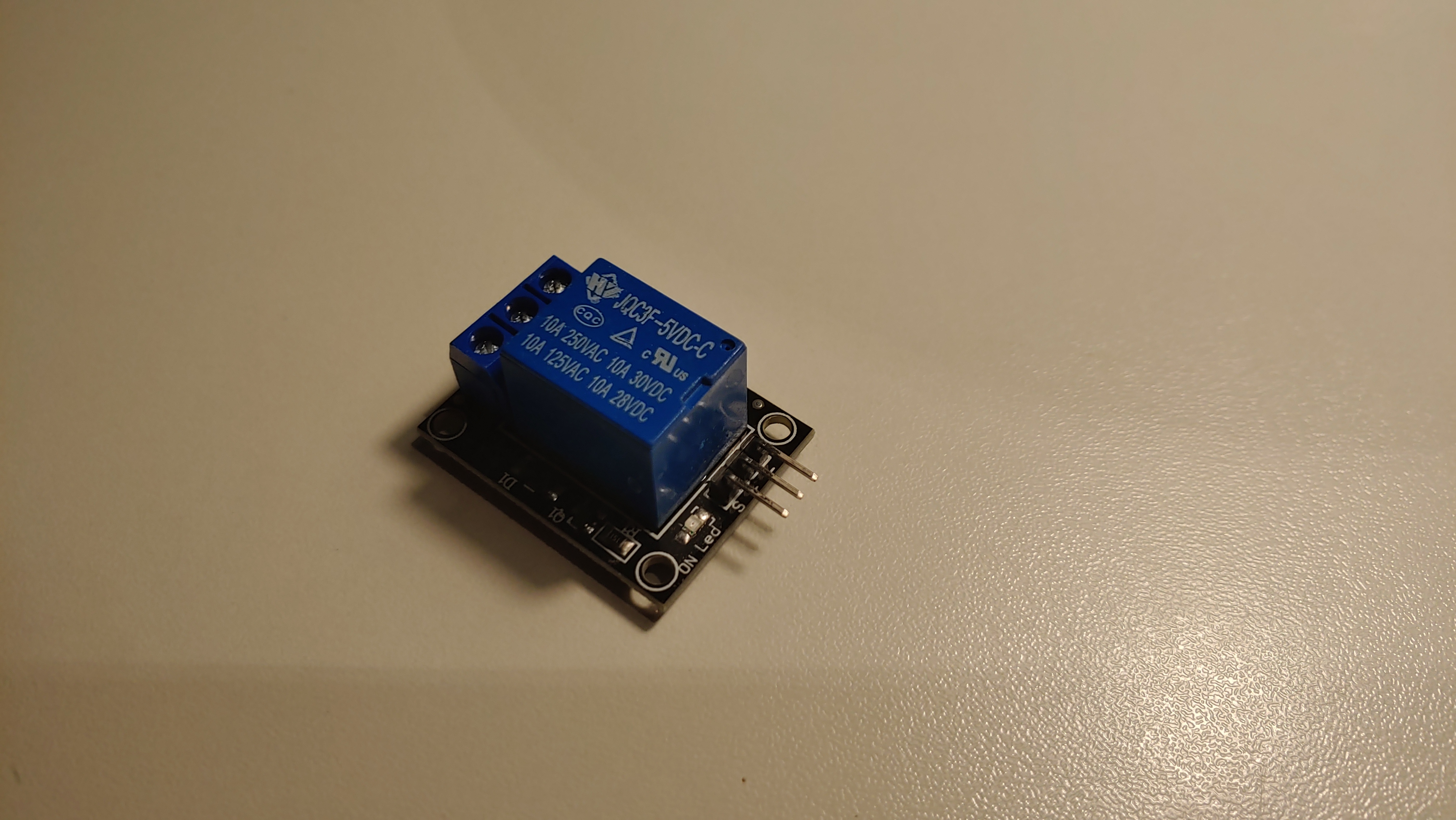
- 3V3 Relay
- Magnets (height: 2mm, diameter: 5mm)
- barrel jack
- [Optional: for easier disconnections] JST 2-pin connector
Software:
Tools:
- 3D-printer
- hot glue (gun)
Files:
Building the LED Controller
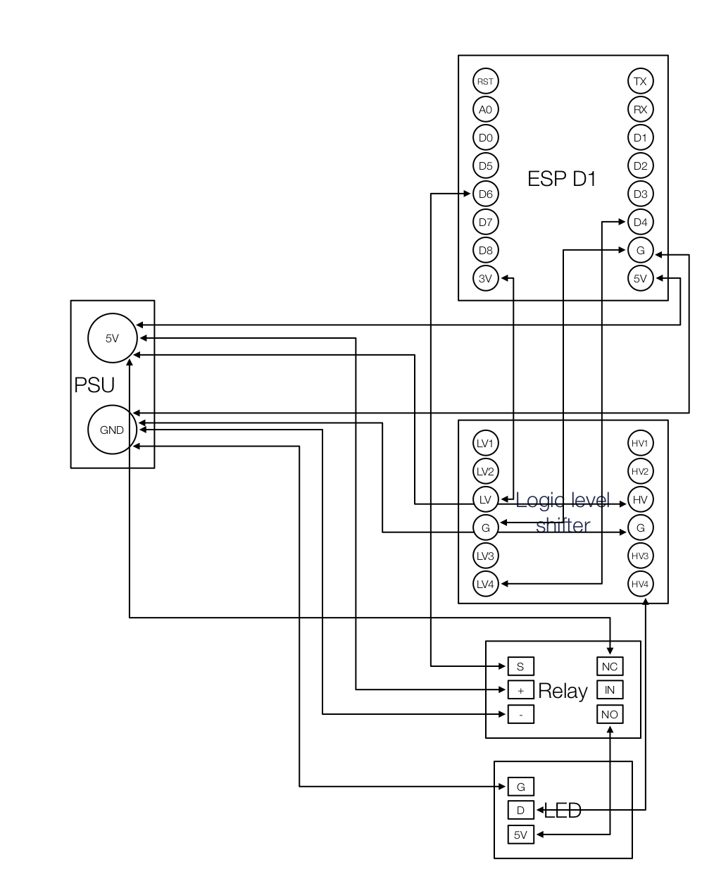
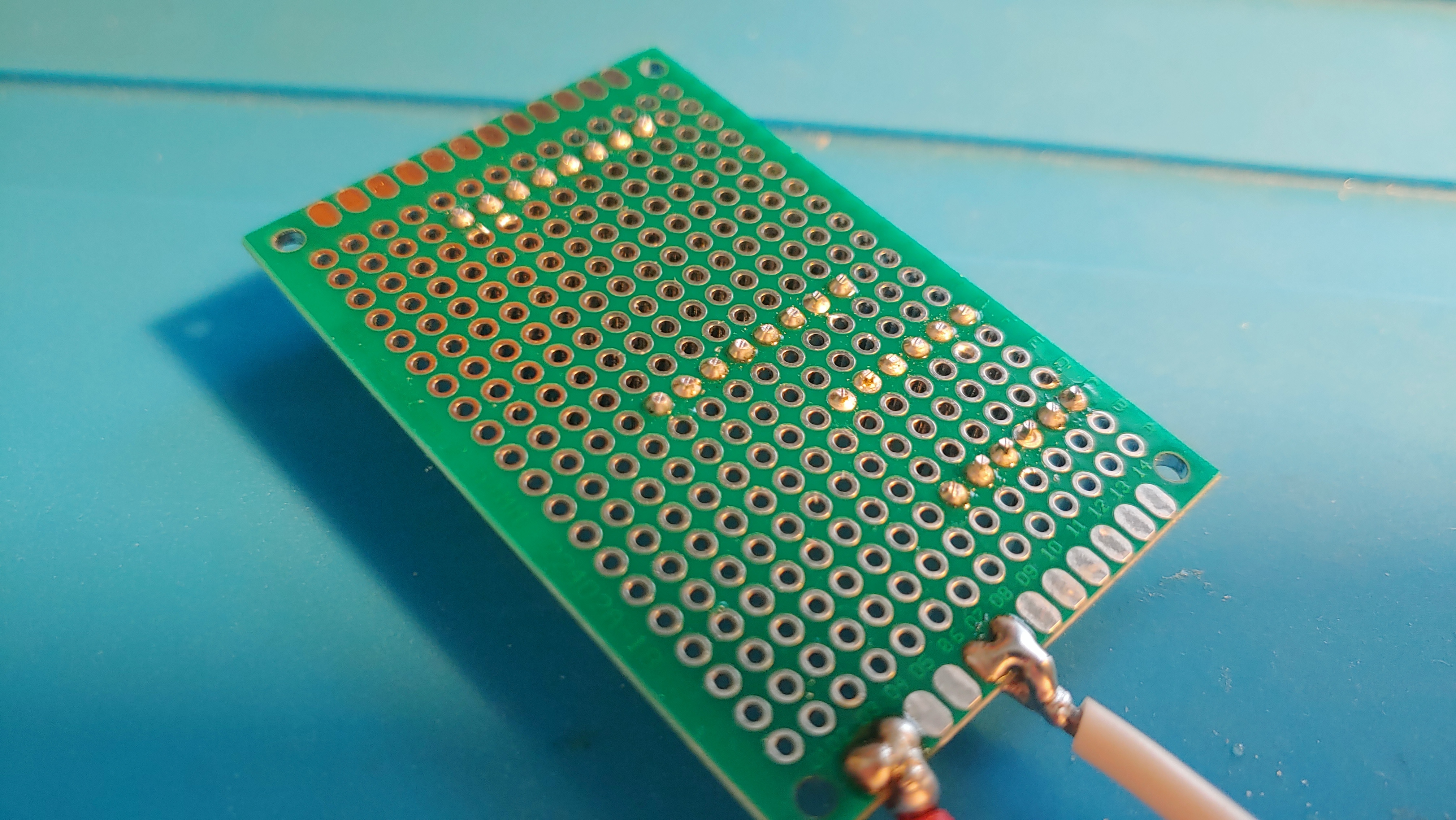
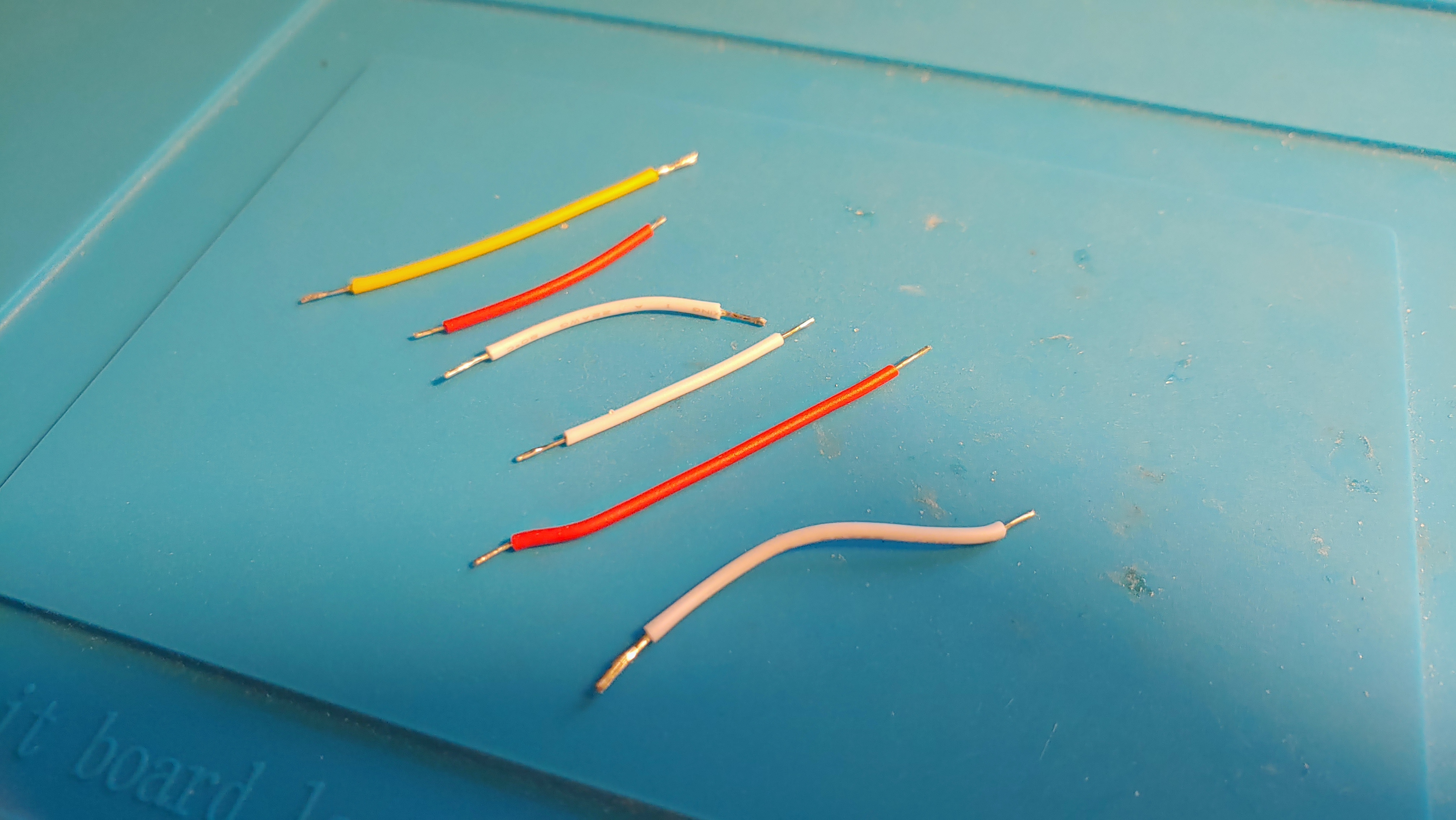
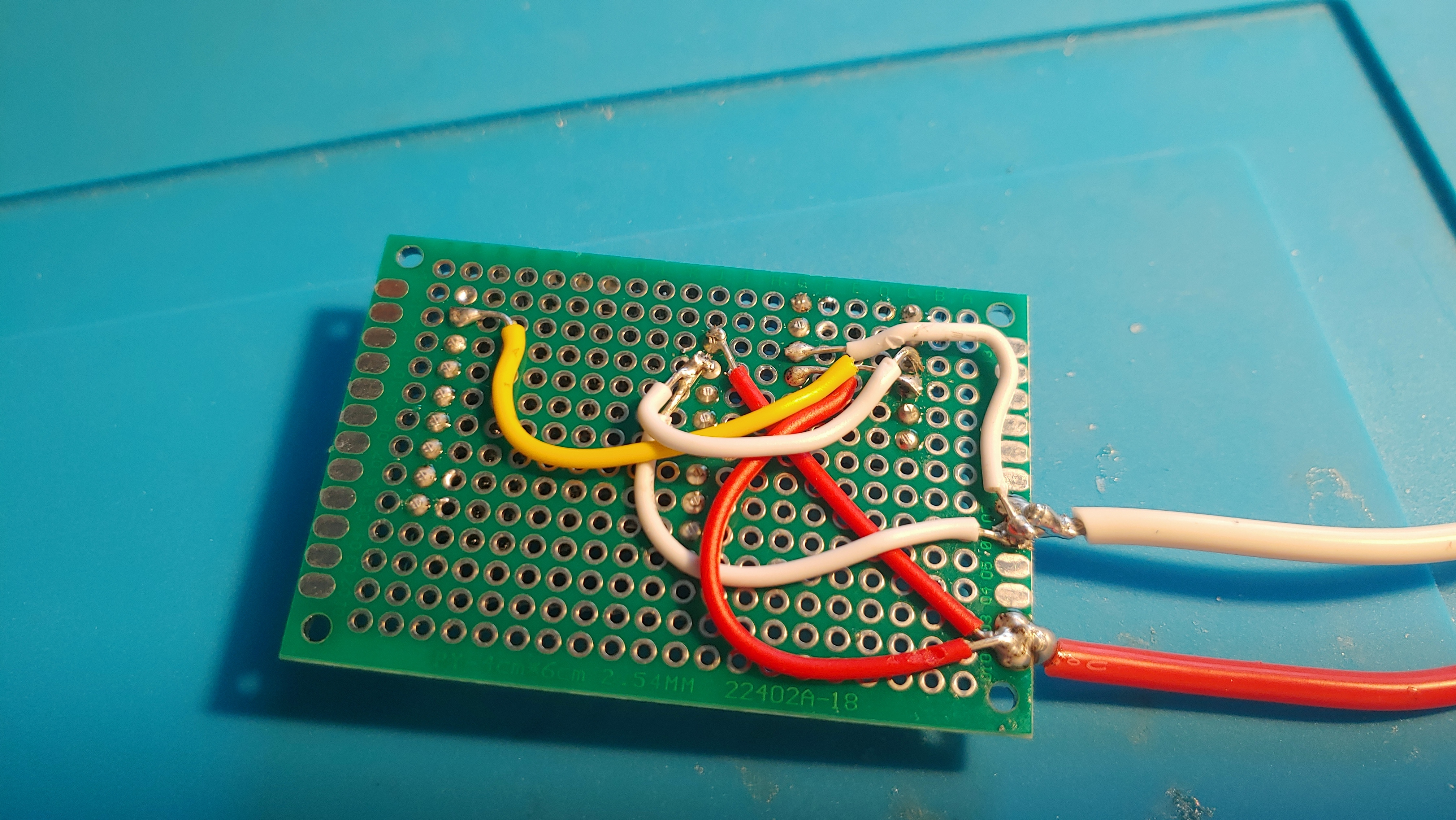
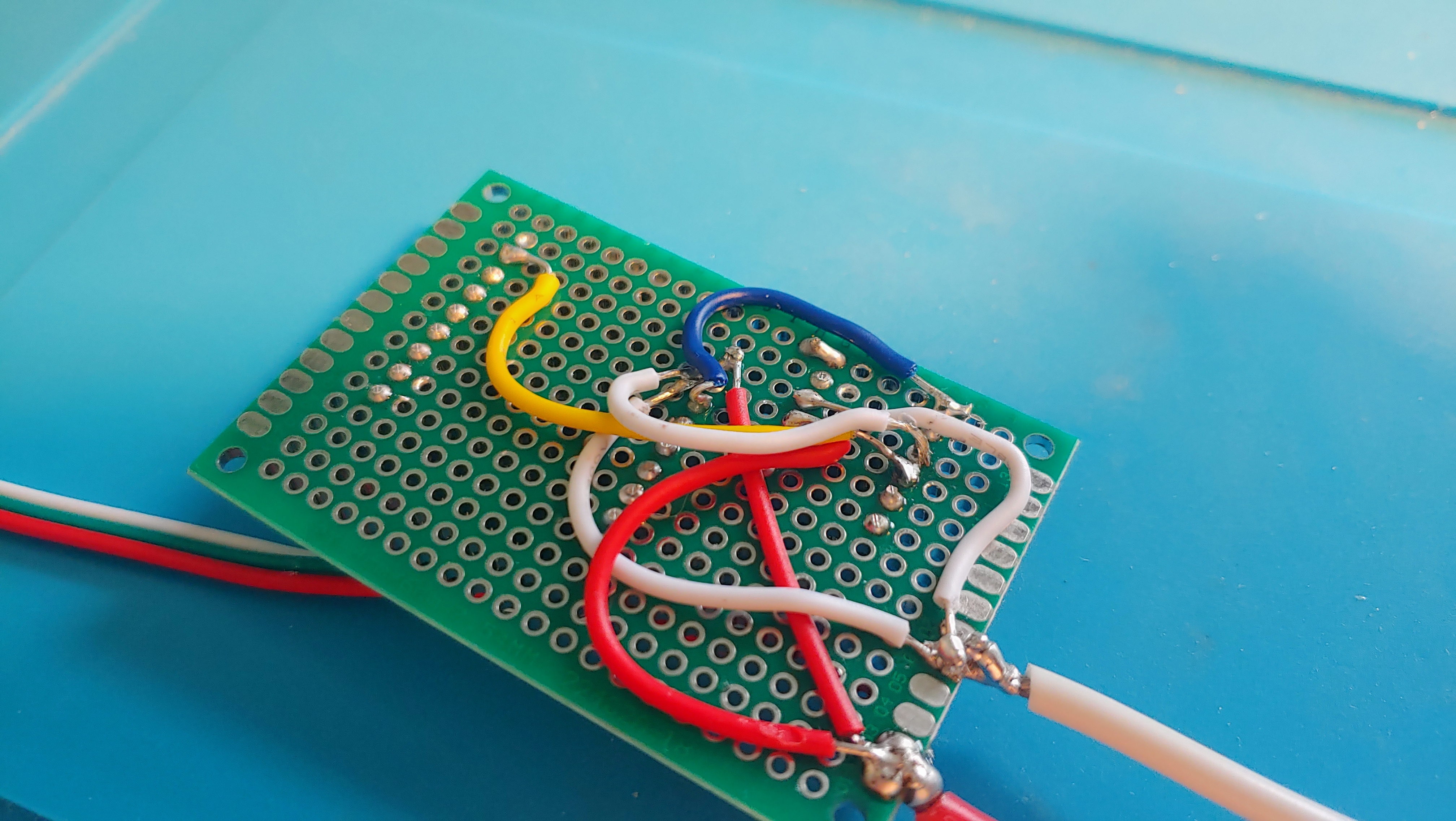
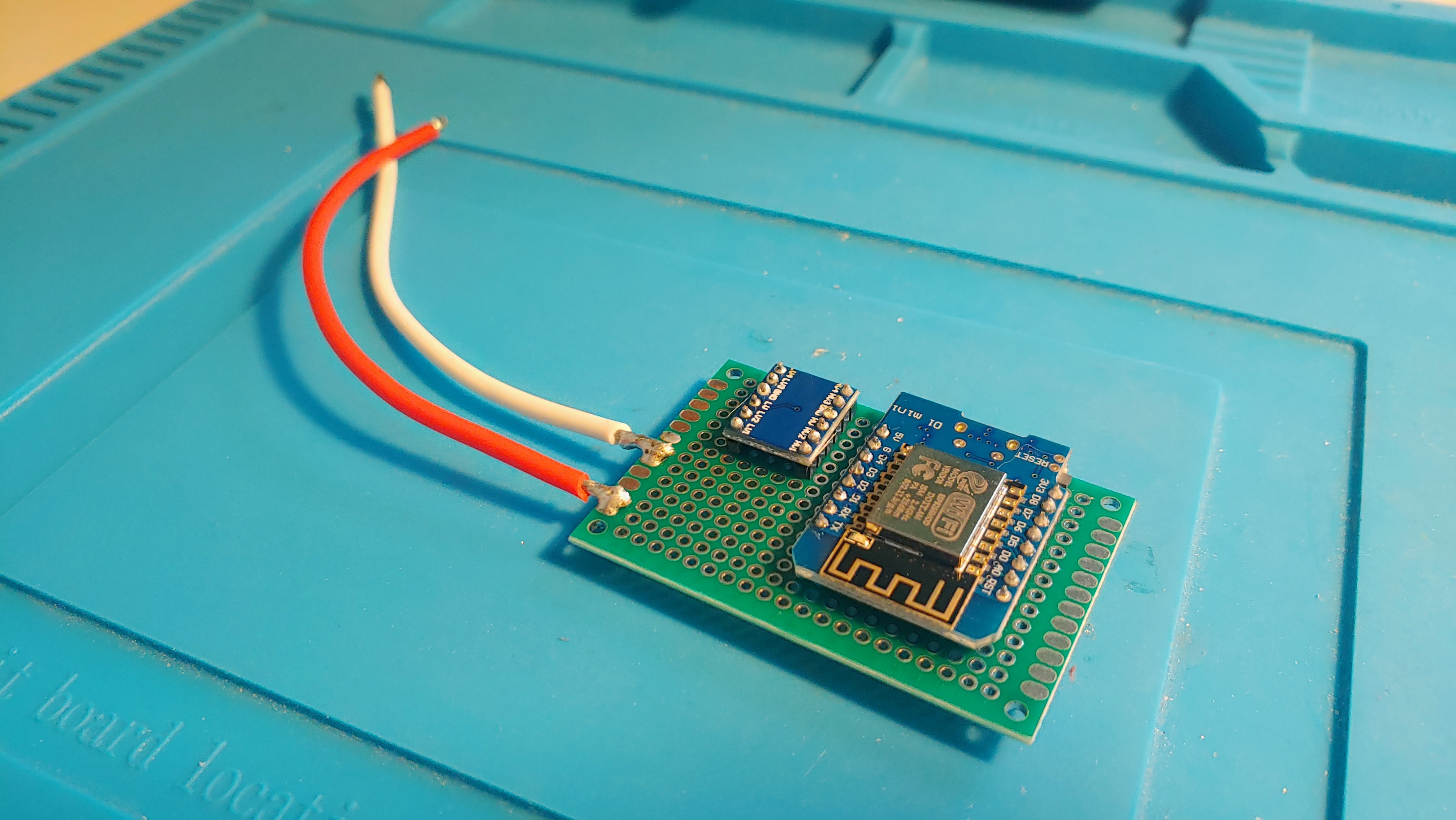
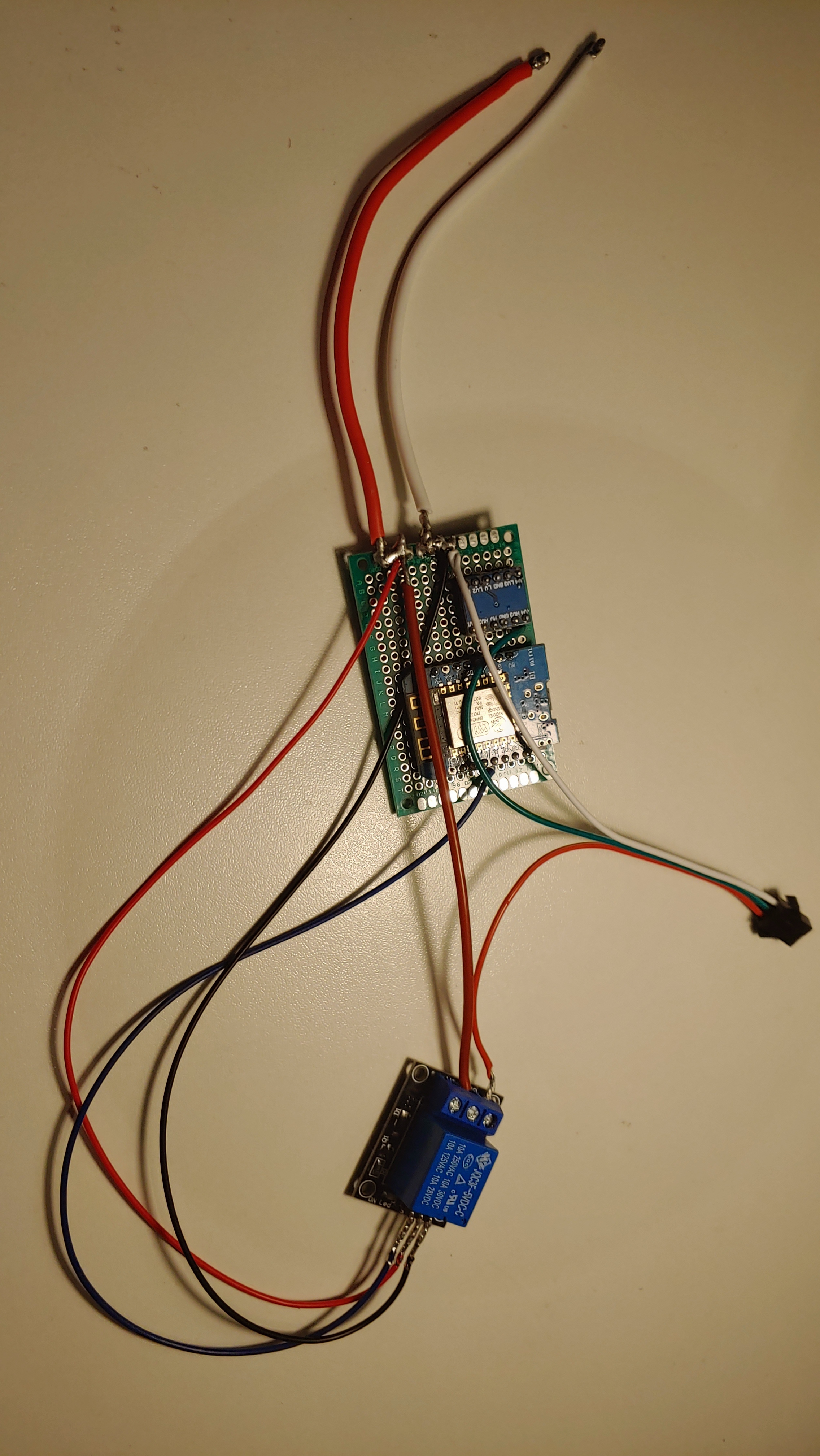
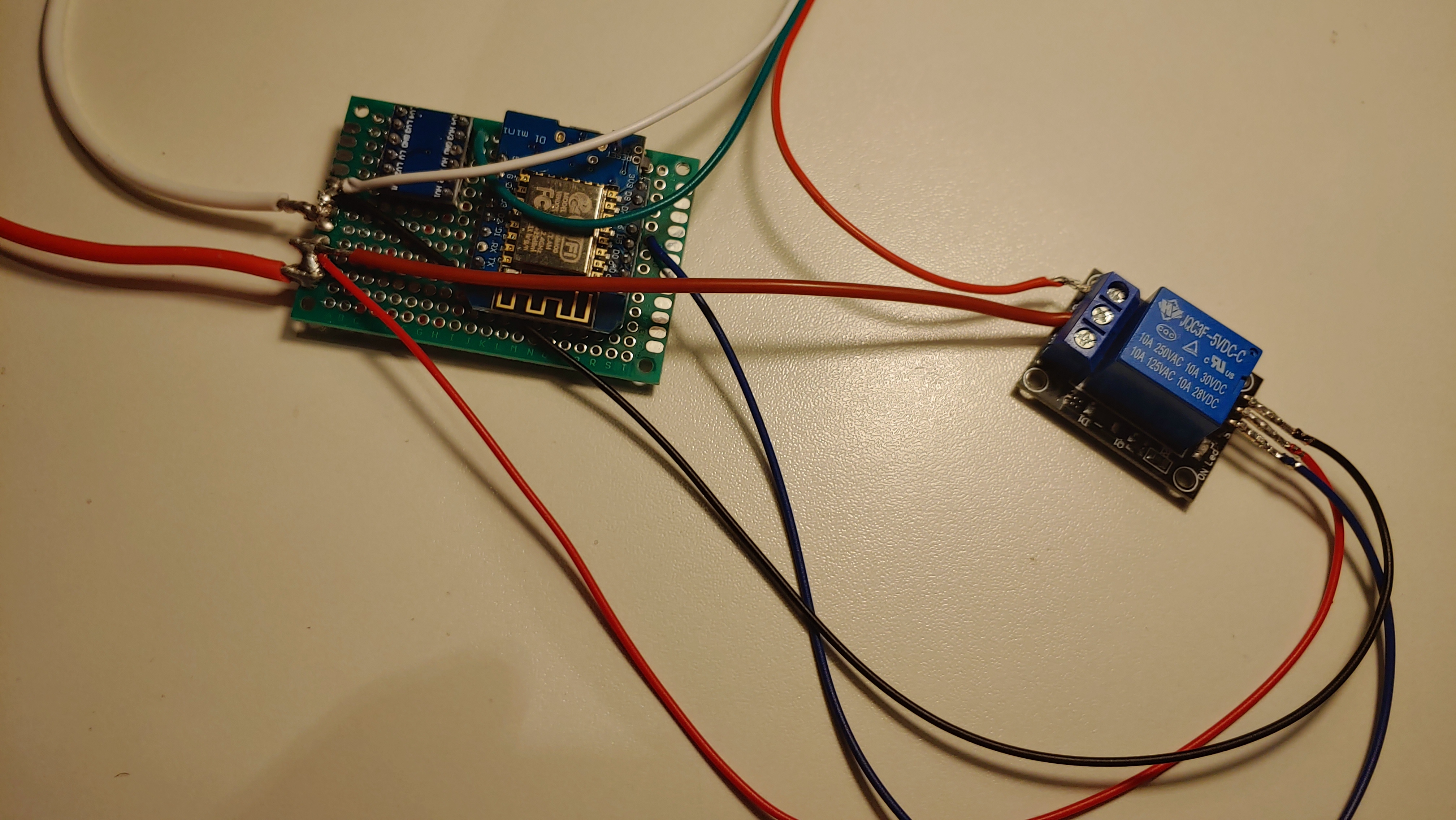
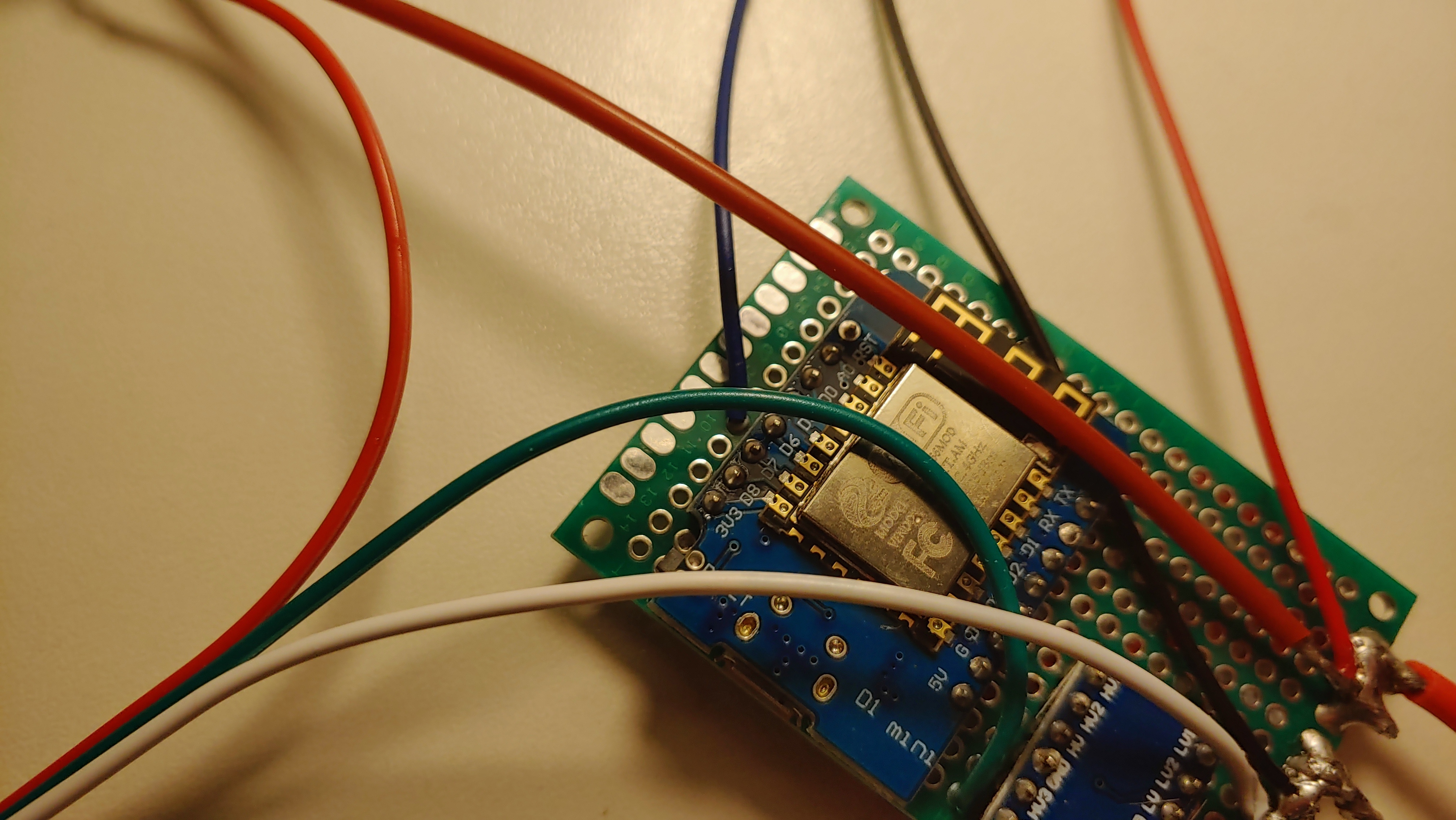
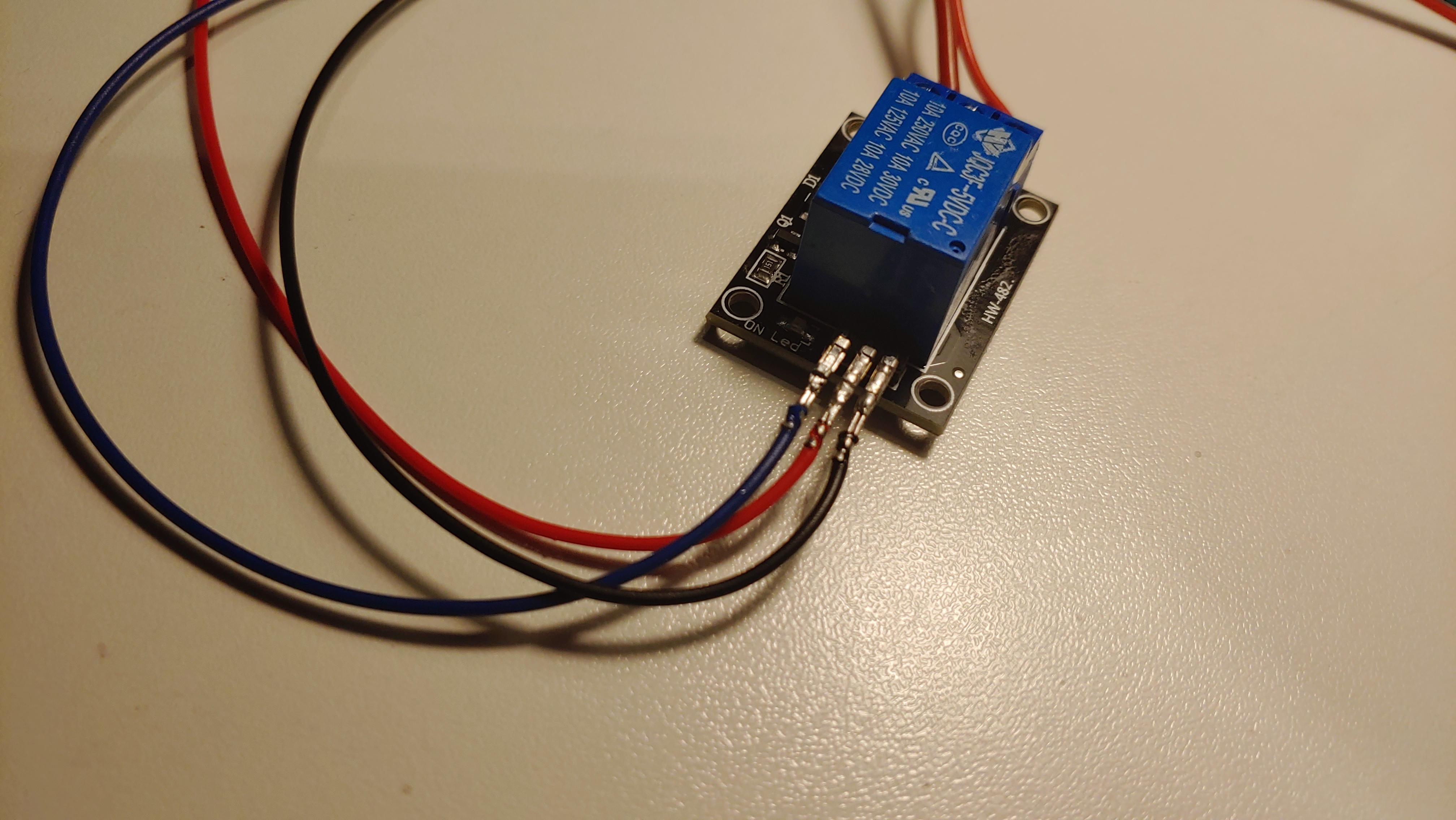
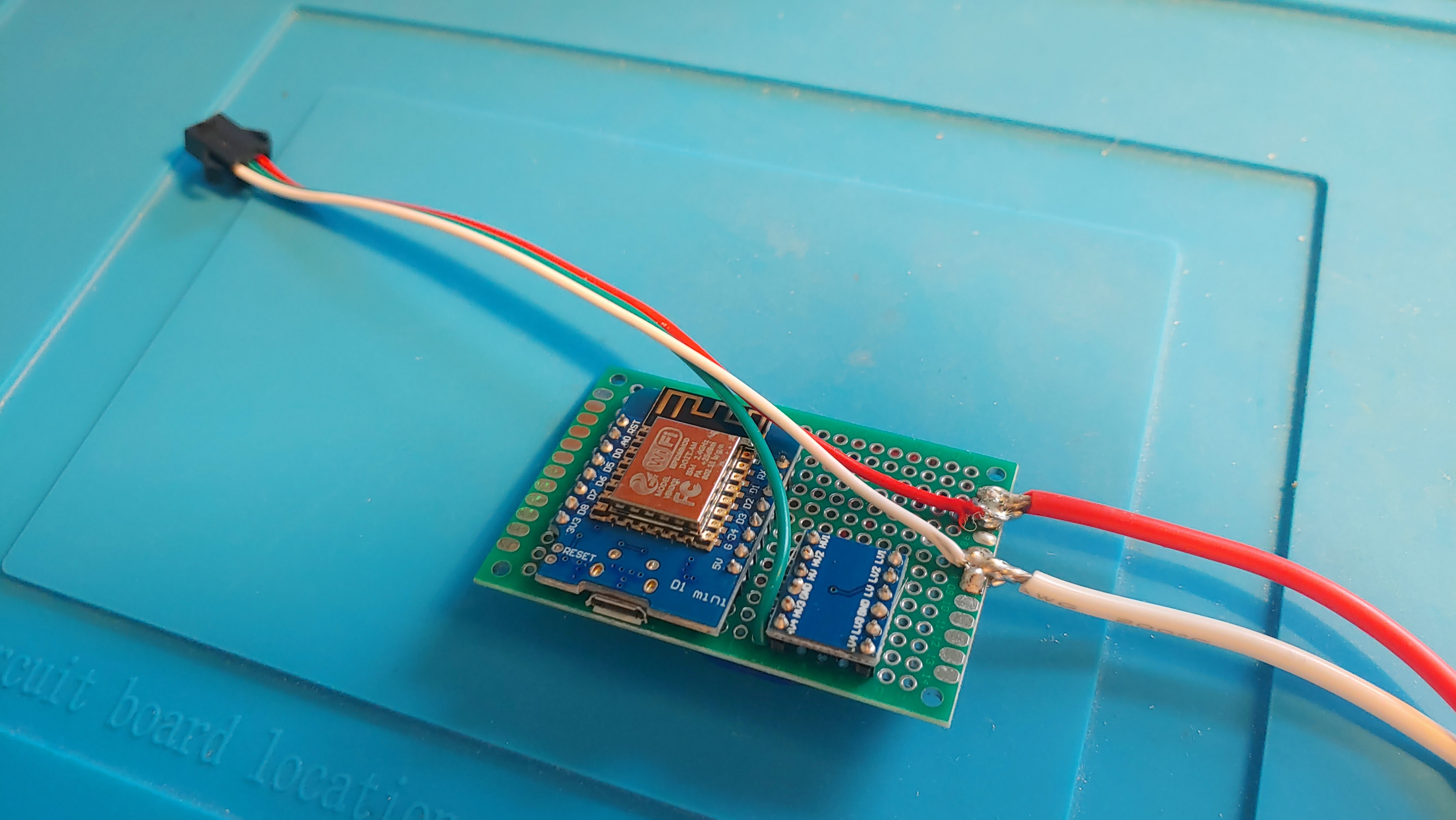


You need to connect the components as shown in the first schematic.
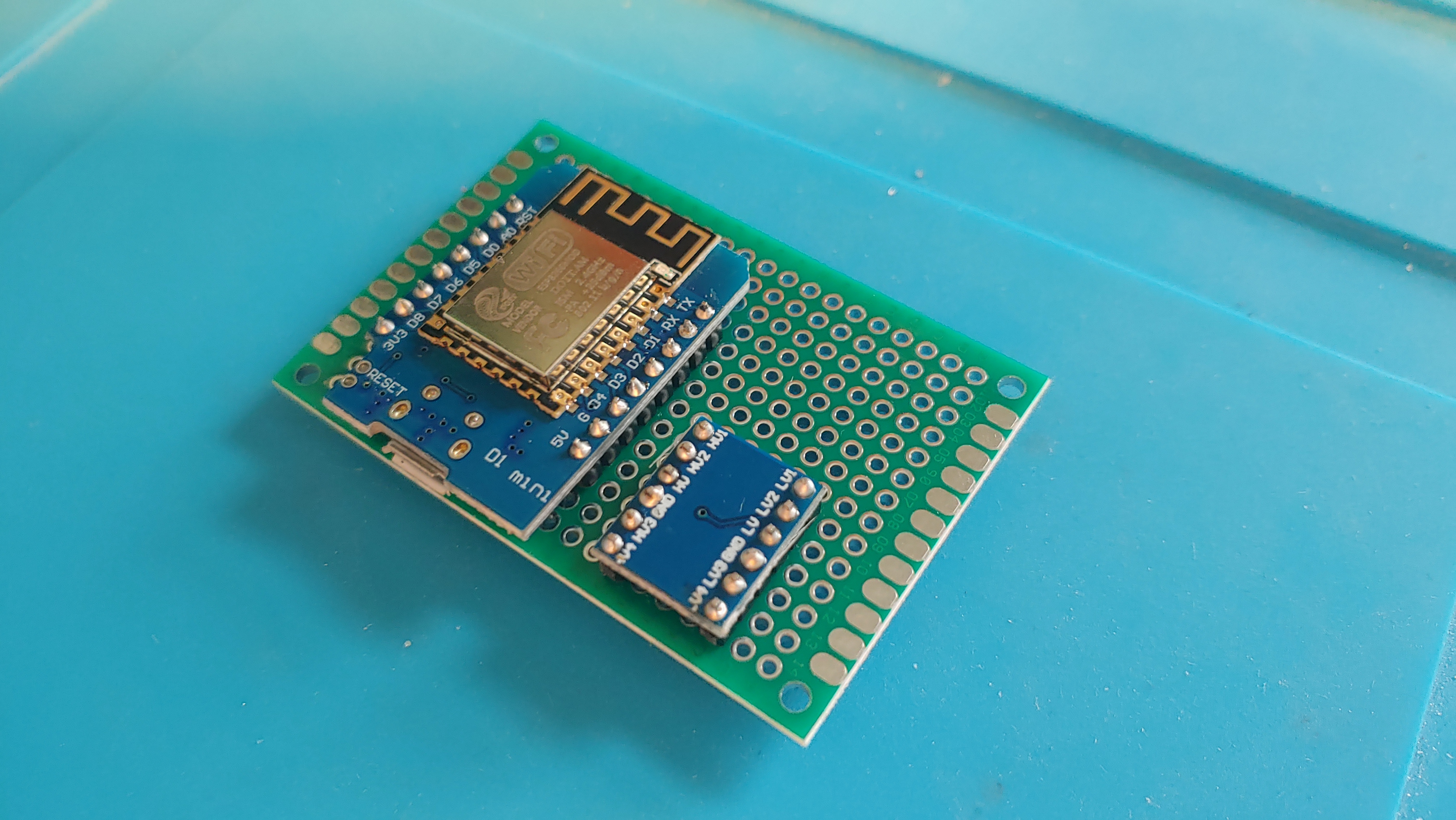
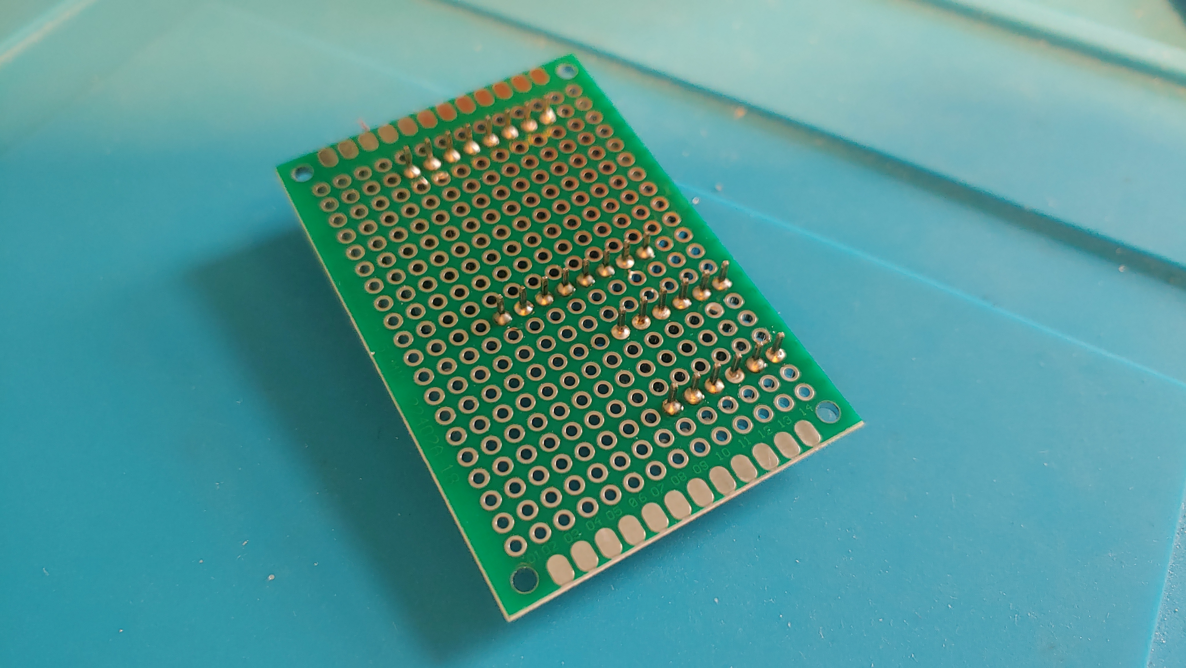
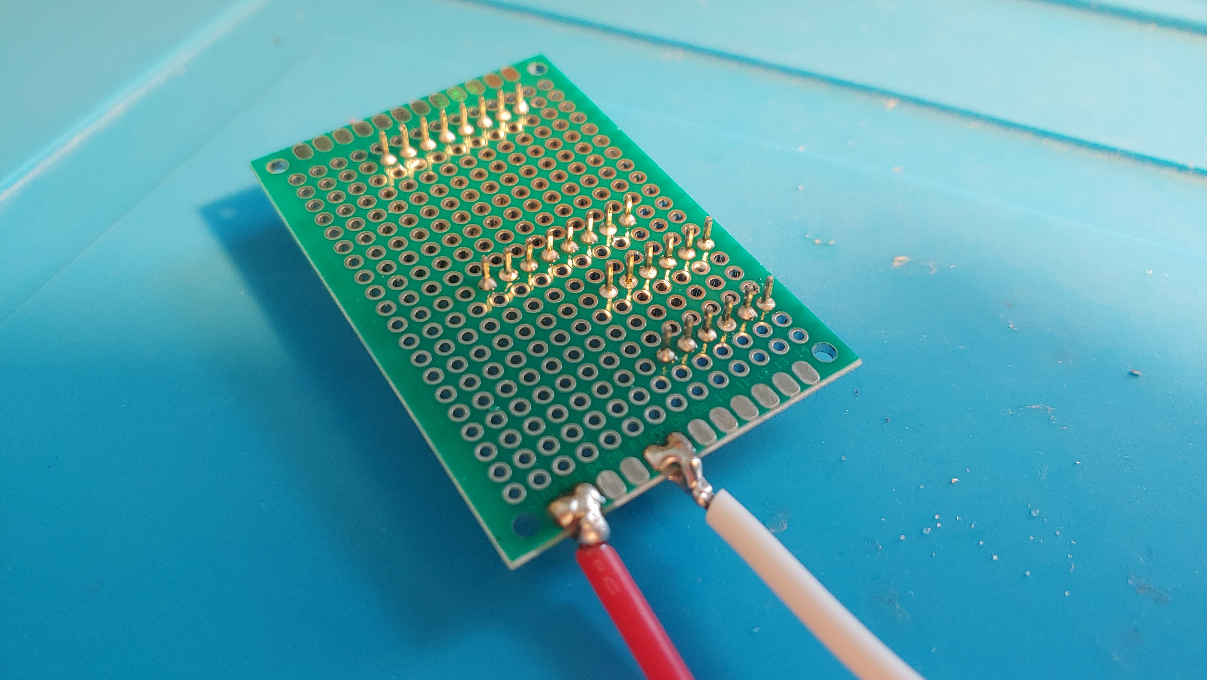
First, you need to solder the ESP and the logic level shifter to the PCB as shown in the second image. The Power connection is next. I like to first solder the incoming power wires to the PCB's side. But you can directly connect it to the ESP and voltage level converter. Optionally you can now cut off all the pins which stand out from the PCB like in the fifth image.
The next step is to connect the ESP and the voltage converter. For this connect the D4 pin of the ESP with one of the Low-Level Pins of the converter.
Next, you will connect the relay. To control a relay WLED uses the D6 pin. Therefore connect the D6 pin with the S (source/data) pin of the relay.
One LED can use up to 60mA when set to the brightest wight. If you want to use every LED of the 93 LEDs at the brightest white you will need a PSU which can supply (img. 16): 5.6A
However, a PSU which is always running at its maximum specification is never good therefore I would recommend using at maximum ~80%. Using some simple math (img. 17) I would recommend a PSU with a maximum of 7A at least.
However, I am using here a PSU which can provide 4A which is enough for me.
Note: It is possible to leave the level shifter out. But with very few boards (for me 1 out of20) you can have the problem that the LEDs do not correctly trigger.
Setting Up the LED's
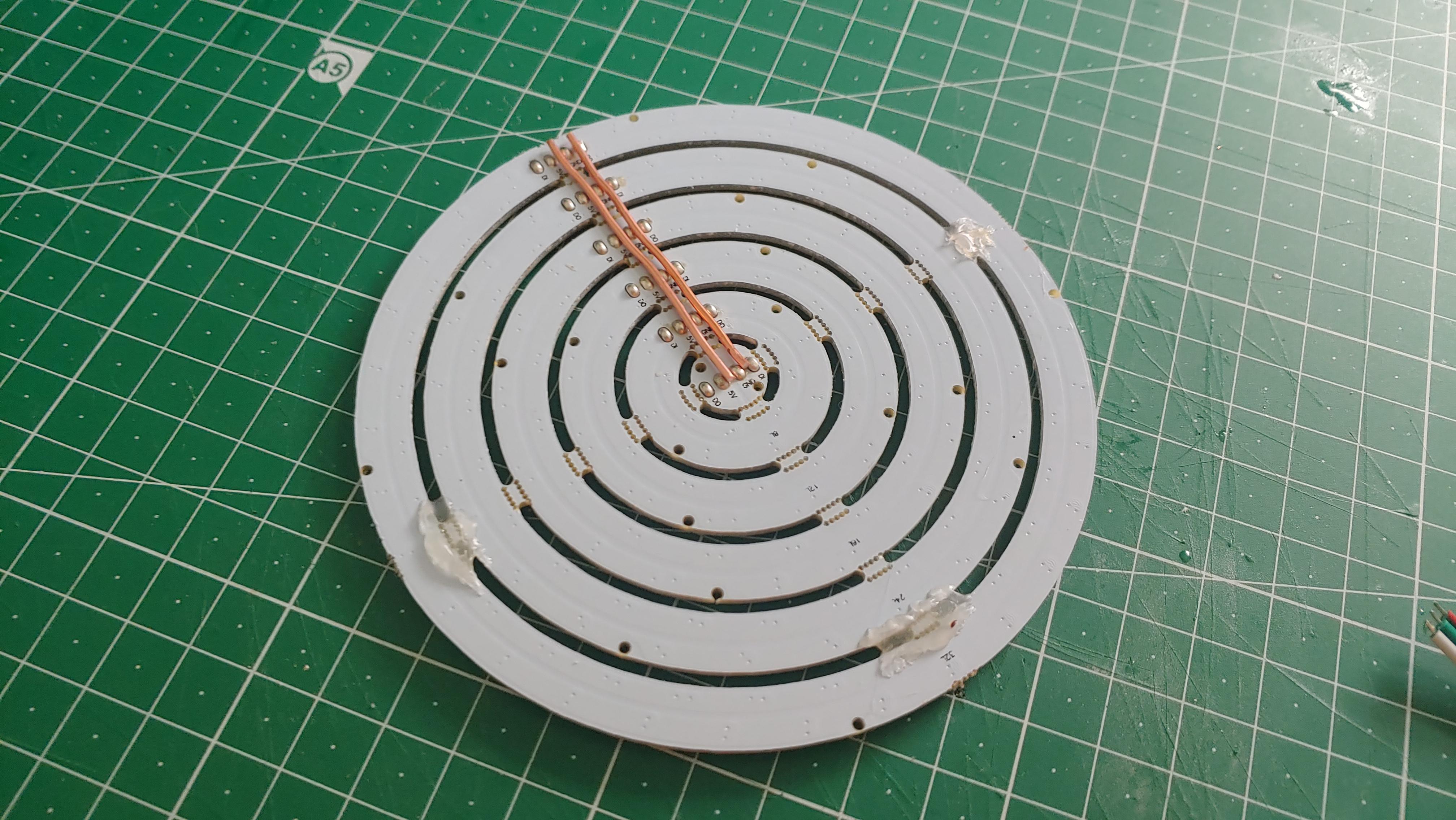
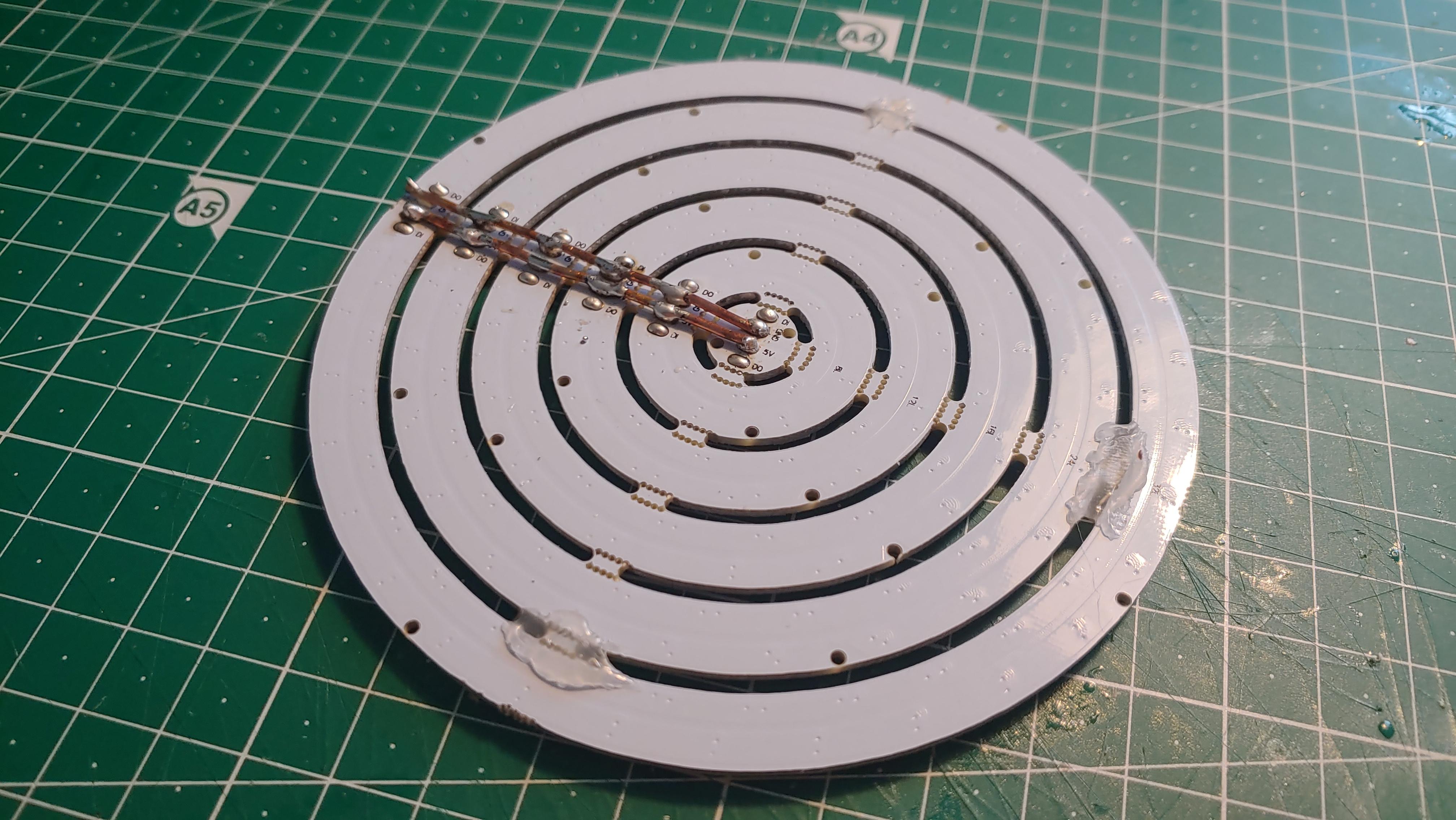
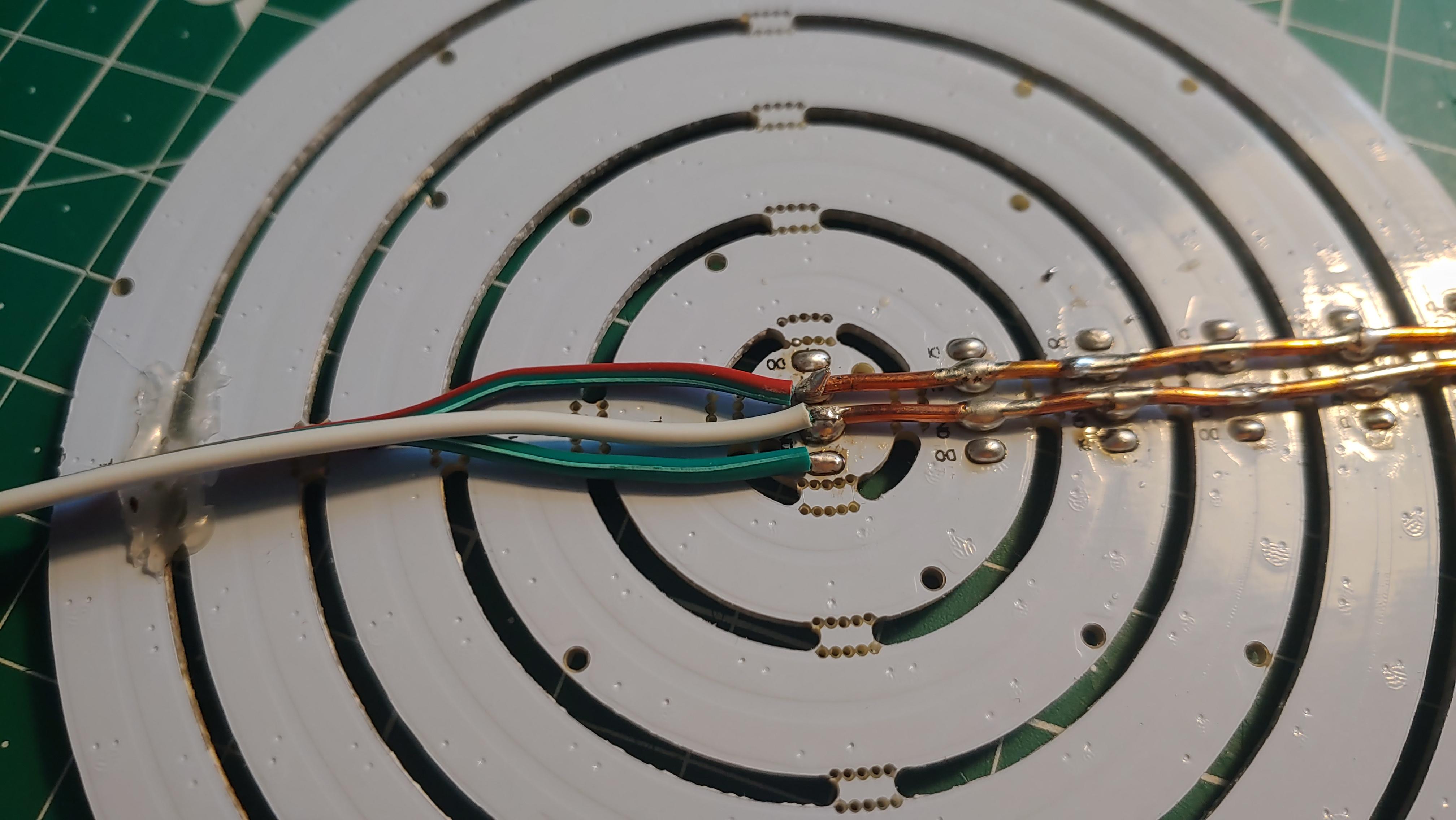
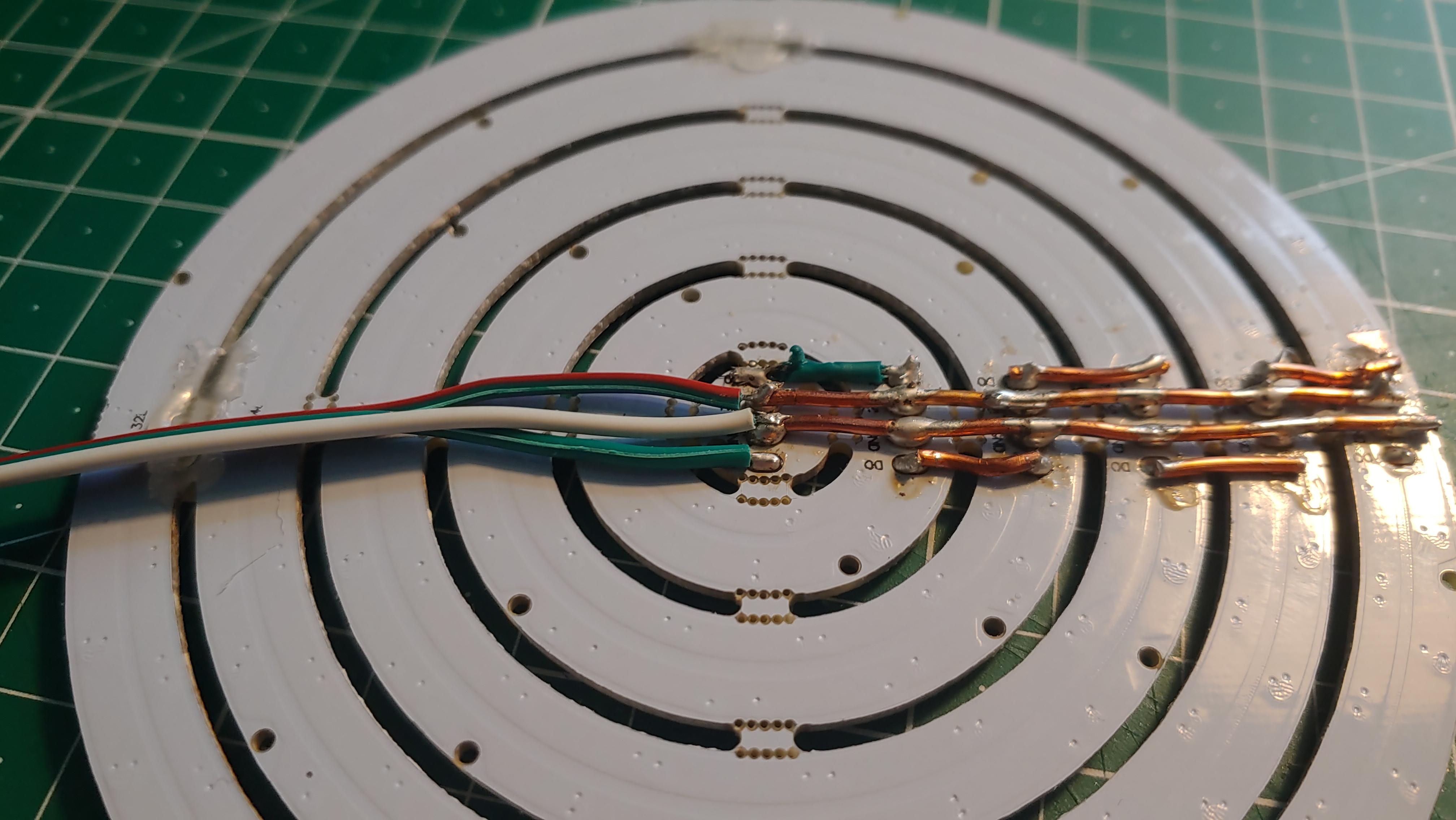
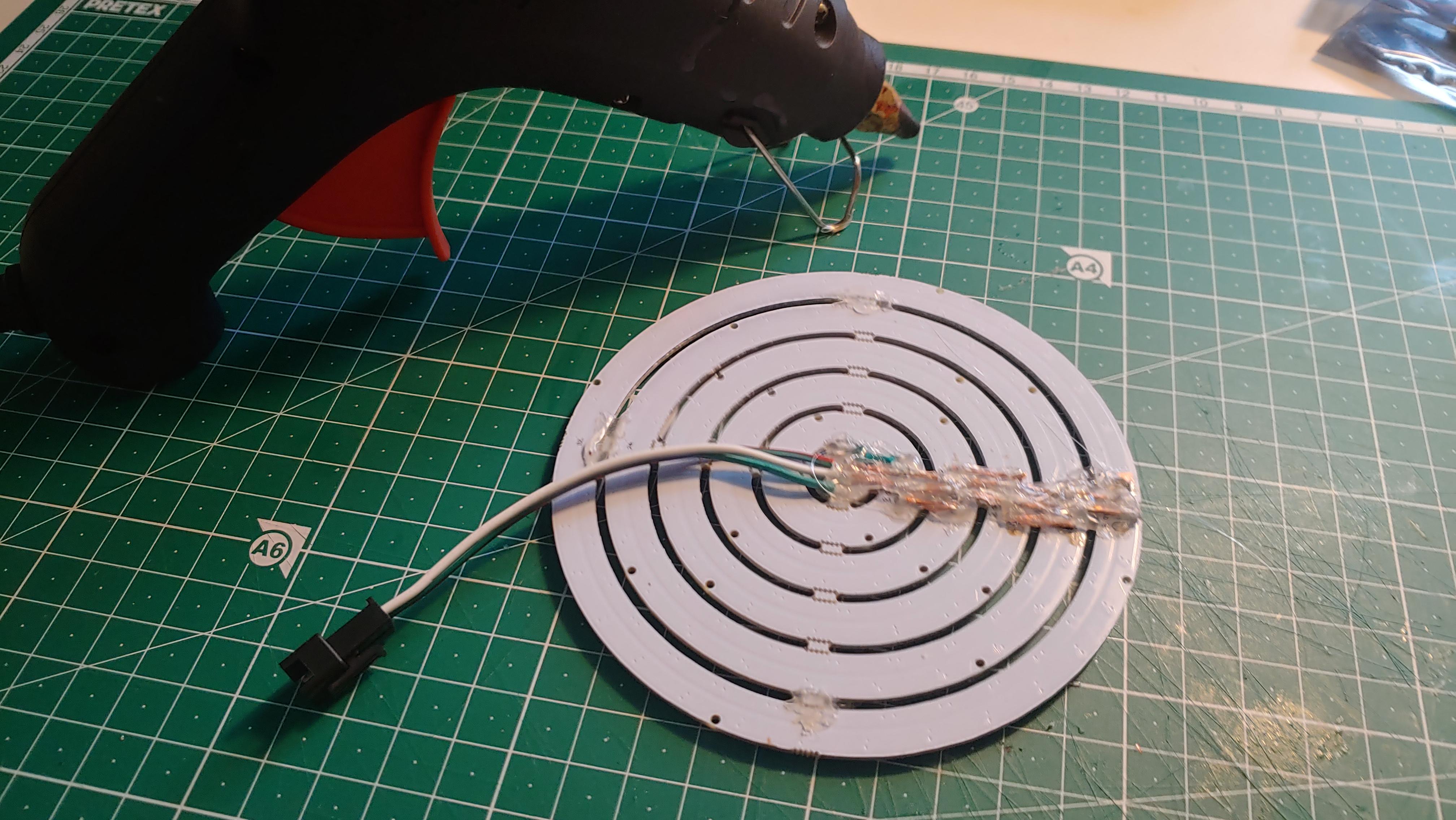
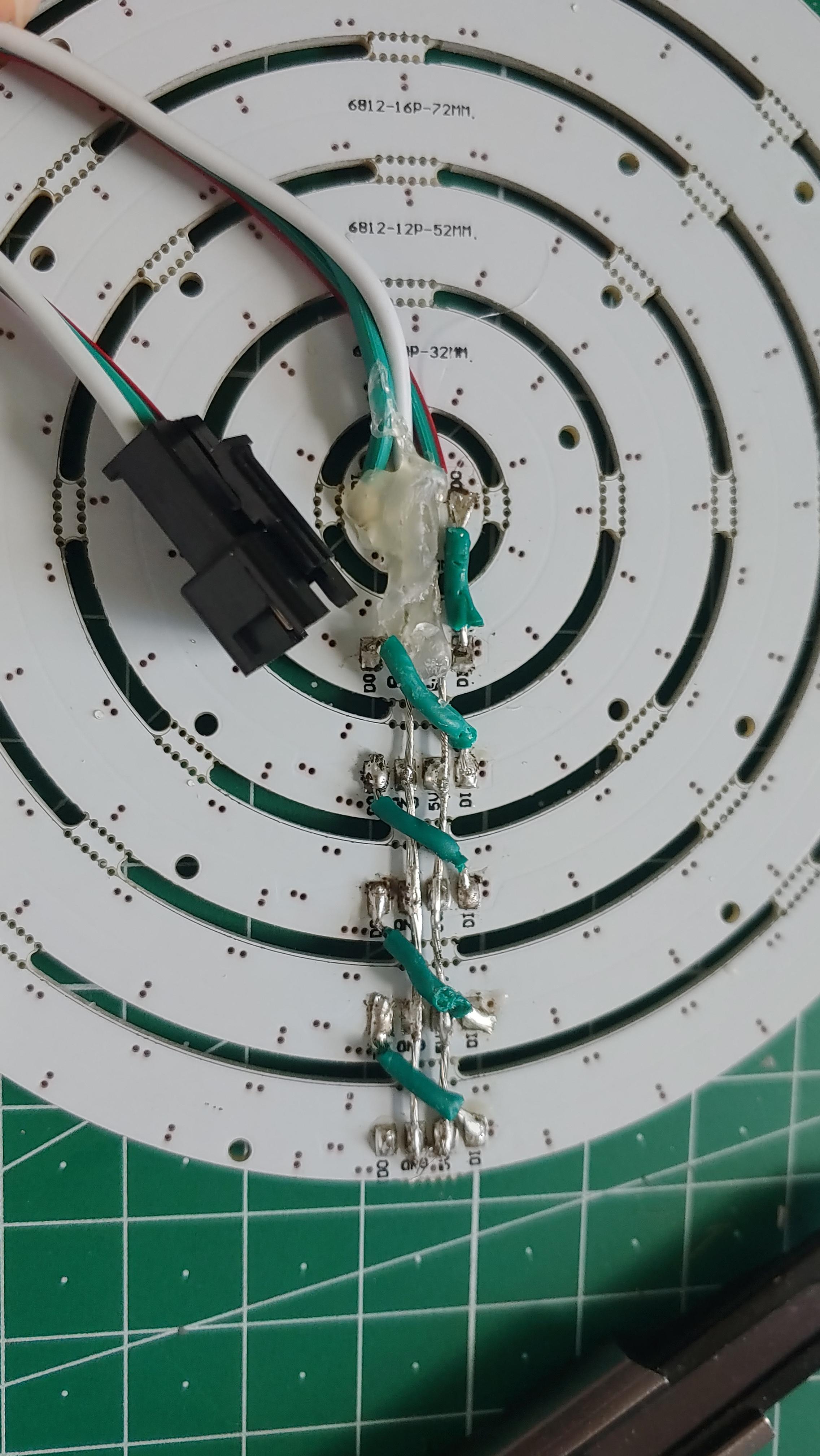
Now you will connect the LED-rings.
You should use thick wires for the 5V because the LEDs will draw much current. I am using a PSU which can deliver up to 4A. Considering this fact I looked up which AWG value I need and decided AWG 20 will be a good fit.
First, connect all 5V and GND inputs of the rings with long wires (image 1&2). Also add a female 3-pin cable to the DIN, 5V and GND of the inner most ring (image 3).
Next, connect all DIN with the DOUT of the previous ring (image 4).
Lastly use some hot glue to isolate the wires.
Installing the Firmware and Configuring It
Because there is already an awesome open-source software for controlling LEDs with an esp we will be using it. It is called "WLED" Download the firmware from here. You have to choose the board you have used. If you have followed this guide choose the "WLED_0.x.x_ESP8266.bin" (read more about the differences here).
To flash the software to an esp I will be using the "ESPtool" software. It is free and open software written in python. You can download it here or install it with pip.
$ pip install esptool.
Now connect your esp to your computer. You need to figure out the port of your esp. On windows open the "Device manager" and under "Ports (COM & LPT)" you should see the COM-port of your esp. Back in the terminal, you can now flash the firmware to the esp with:
python -m esptool YOUR_COM_PORT write_flash 0x1000 WLED_0.x.x_ESP8266.bin
If you successfully flashed the firmware you should see an open hot spot called "WLED-AP". Connect to it using the password "wled1234" and follow the instructions shown to you. Now you can go to the App store/play store and download the WLED app to control your device. It is also possible to integrate it into your home automation system if you have one (take a look here).
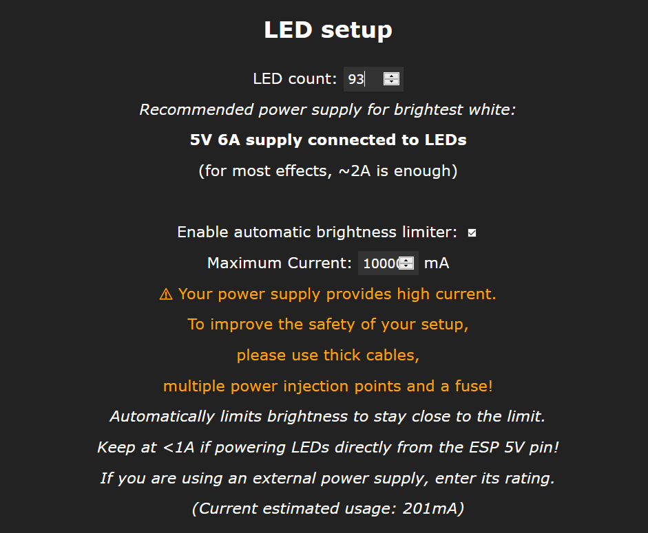
After the download, you have to go in the WLED-app to “Config” → “LED Preferences” and there set the “LED count” to 93 and set the “Maximum Current” to the rated maximum of your power supply. Therefore I recommend 3A.
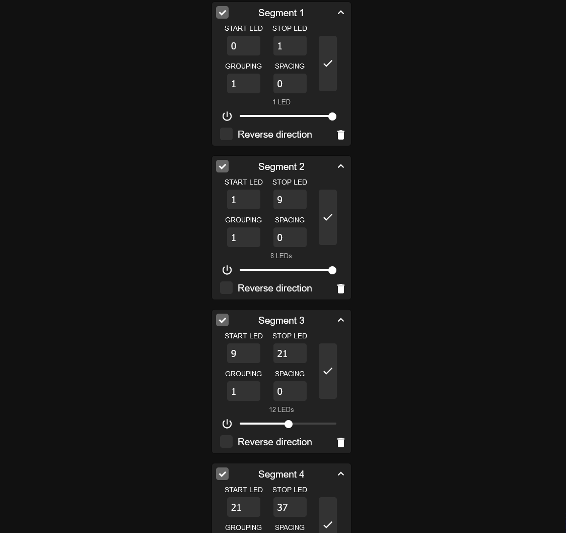
The last step for the software setup is to set every LED ring to its own segment in the software. To do this you need to go to the "Segments"-tab of WLED and make a Segmente for each ring. Use the following limits:
- Segment 0 - 1
- Segment 1 - 9
- Segment 9 - 21
- Segment 21 - 37
- Segment 37 - 61
- Segment 61 - 93
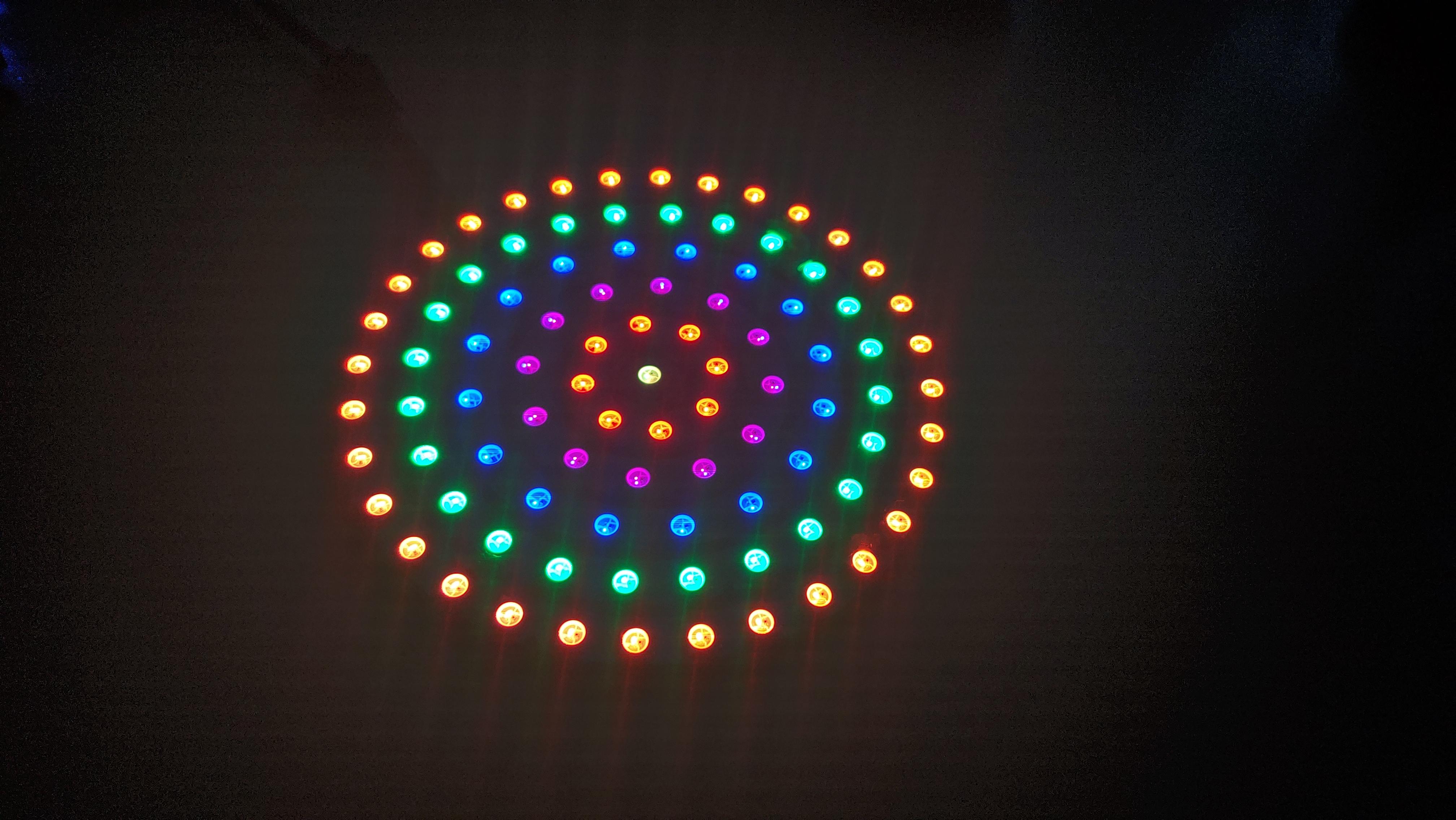
You should now be able to set the color of each ring individually like the last image shows.
Designing and Printing the Base
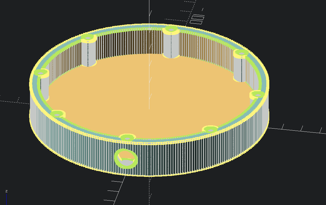
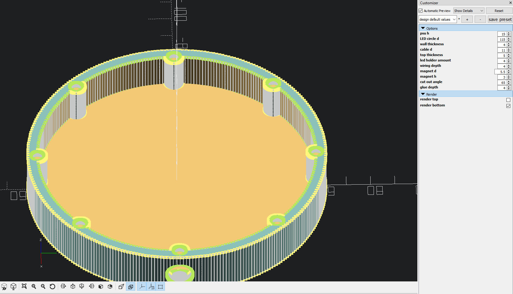
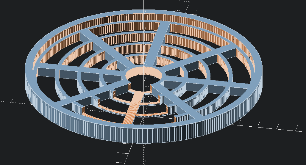
For the base, I wanted enough space to fit the PSU inside of it but also the possibility to scale it for a different PSU (including an external one). That is why I decided to use OpenSCAD. The Base consists of two parts, a bottom one and a top one. They stick together via magnets which should be glued in the small holes.
The ".scad" file which is here provided has different parameters.
You can set the PSU height of your PSU with the "PSU_h" parameter. If you want to use an external one set it to the height of your LED controller as the controller still needs to fit inside of it. Also "cable_d" is a very important setting. You have to set this to the size of your barrel jack or the diameter of your cable.
You can select which part of the base should be rendered in the ''Render"-tab. Now render your settings with F6 and export it with F7.
Lastly, for this step open your slicer of choice and print the base and the top.
Putting It Together
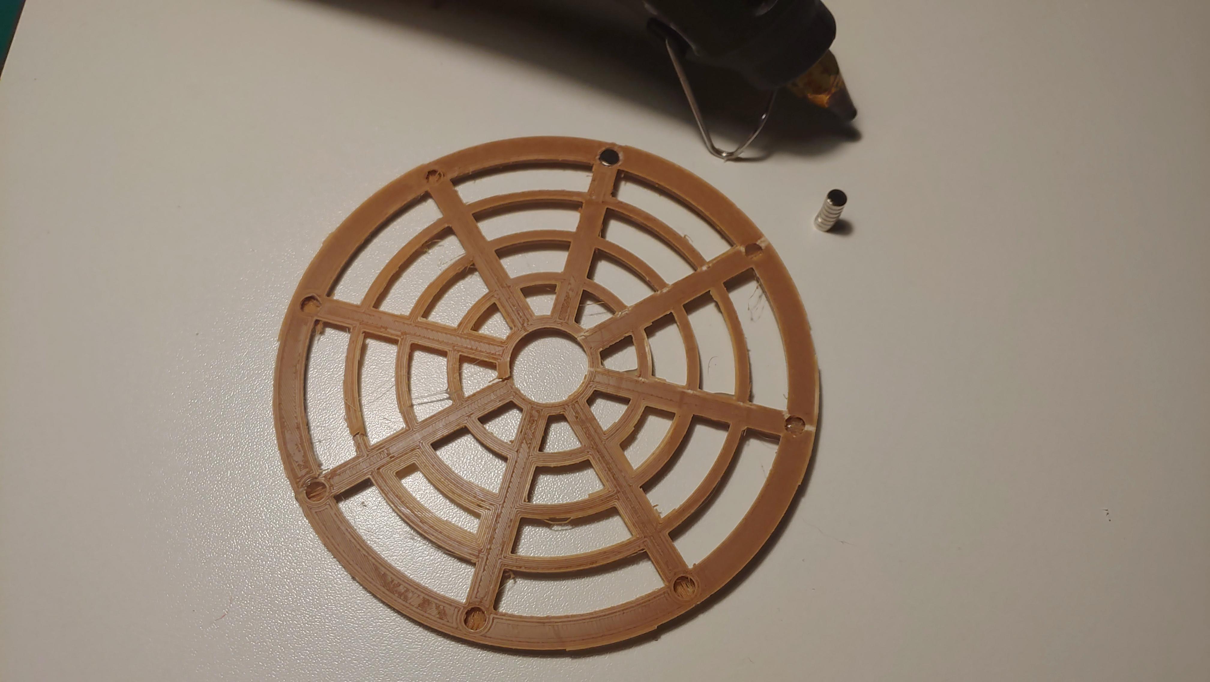
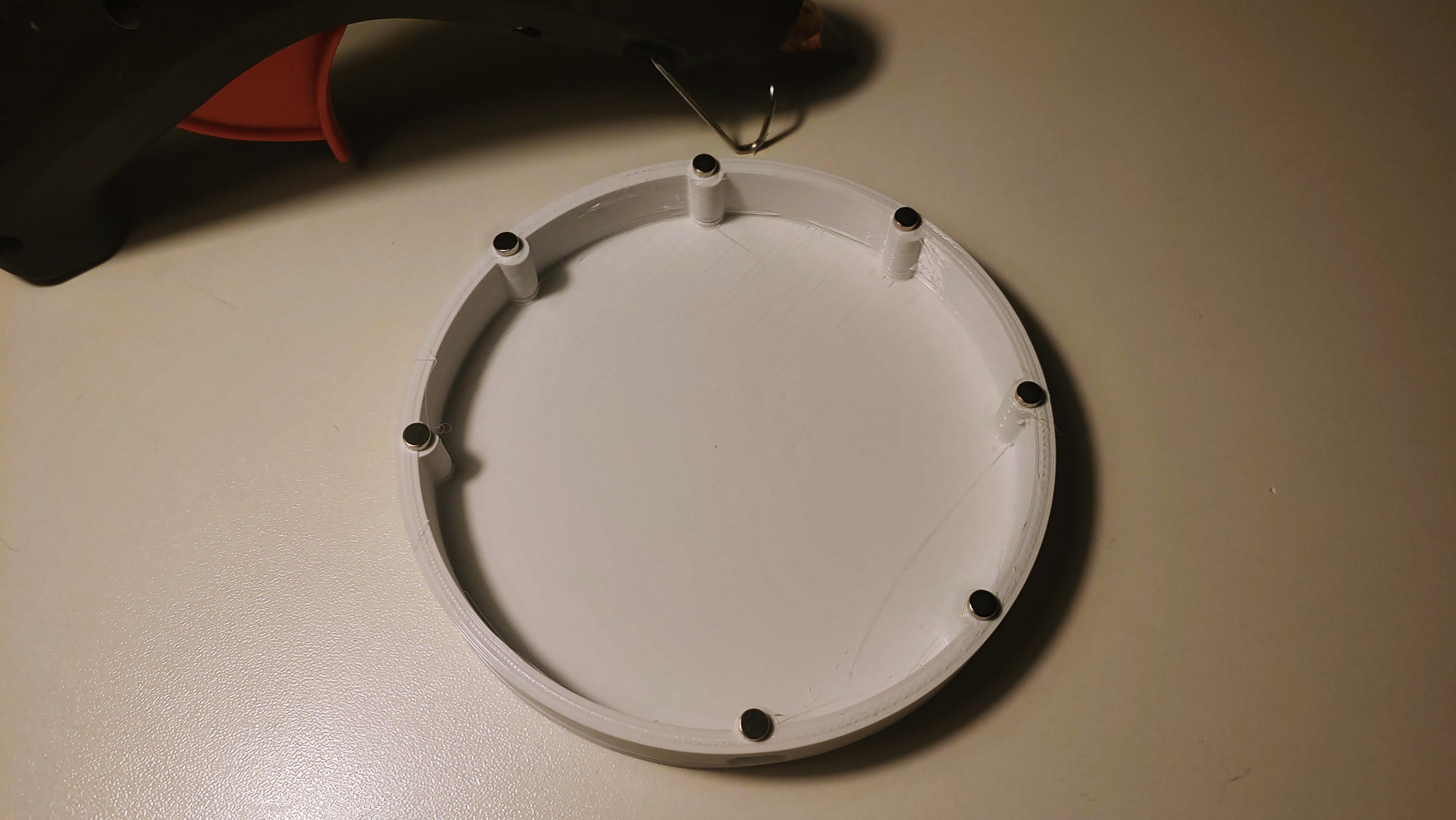
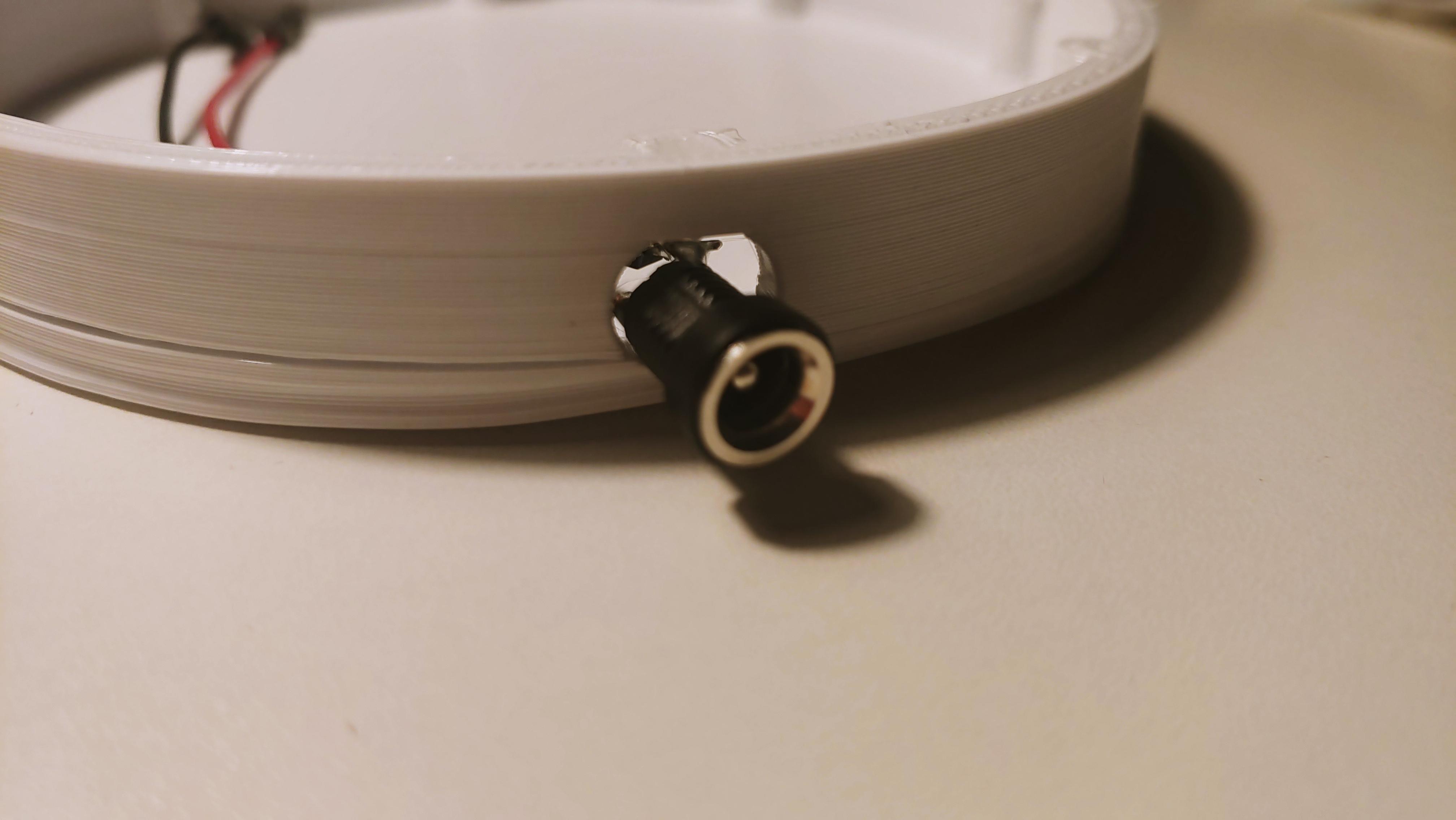
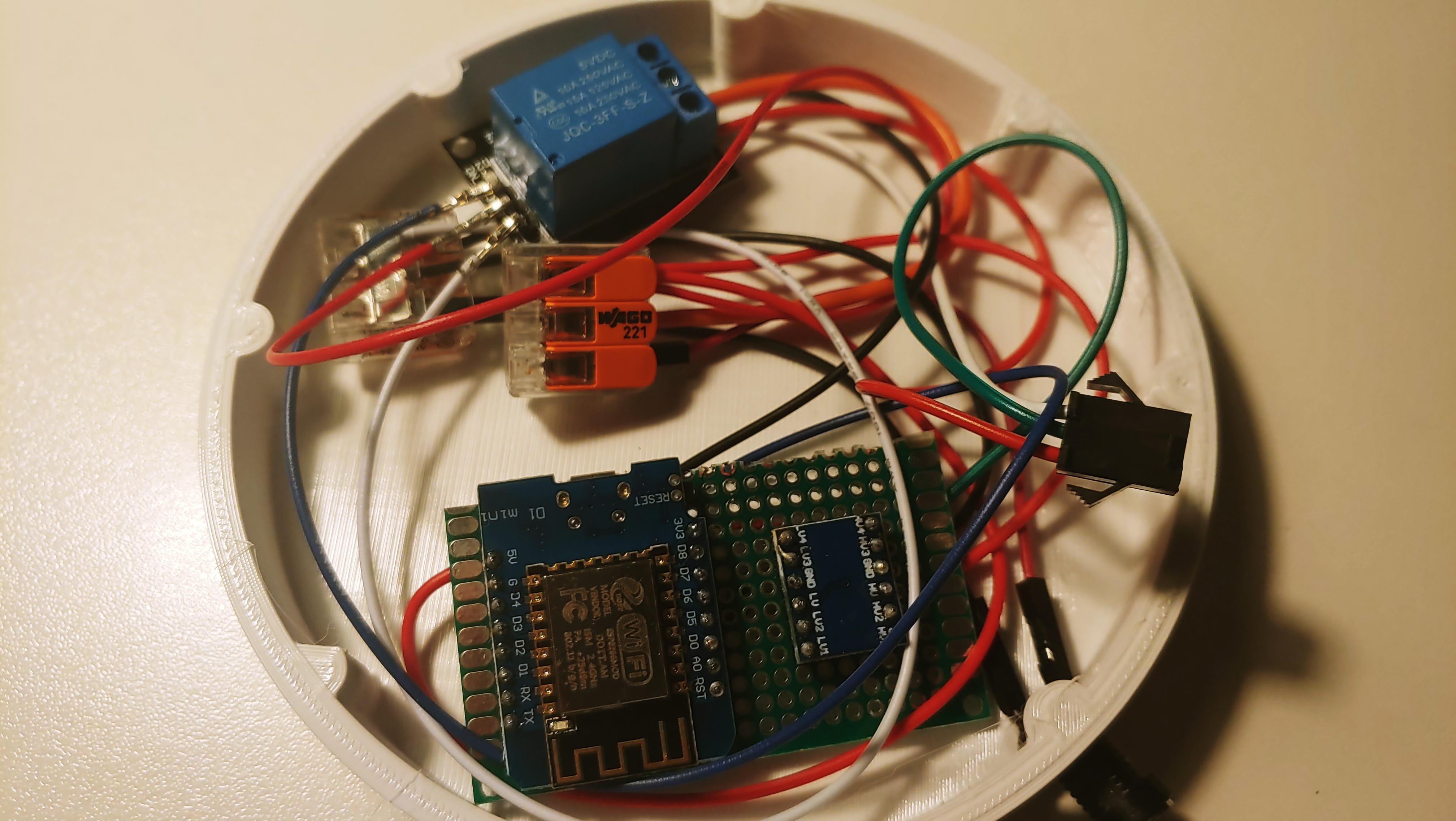
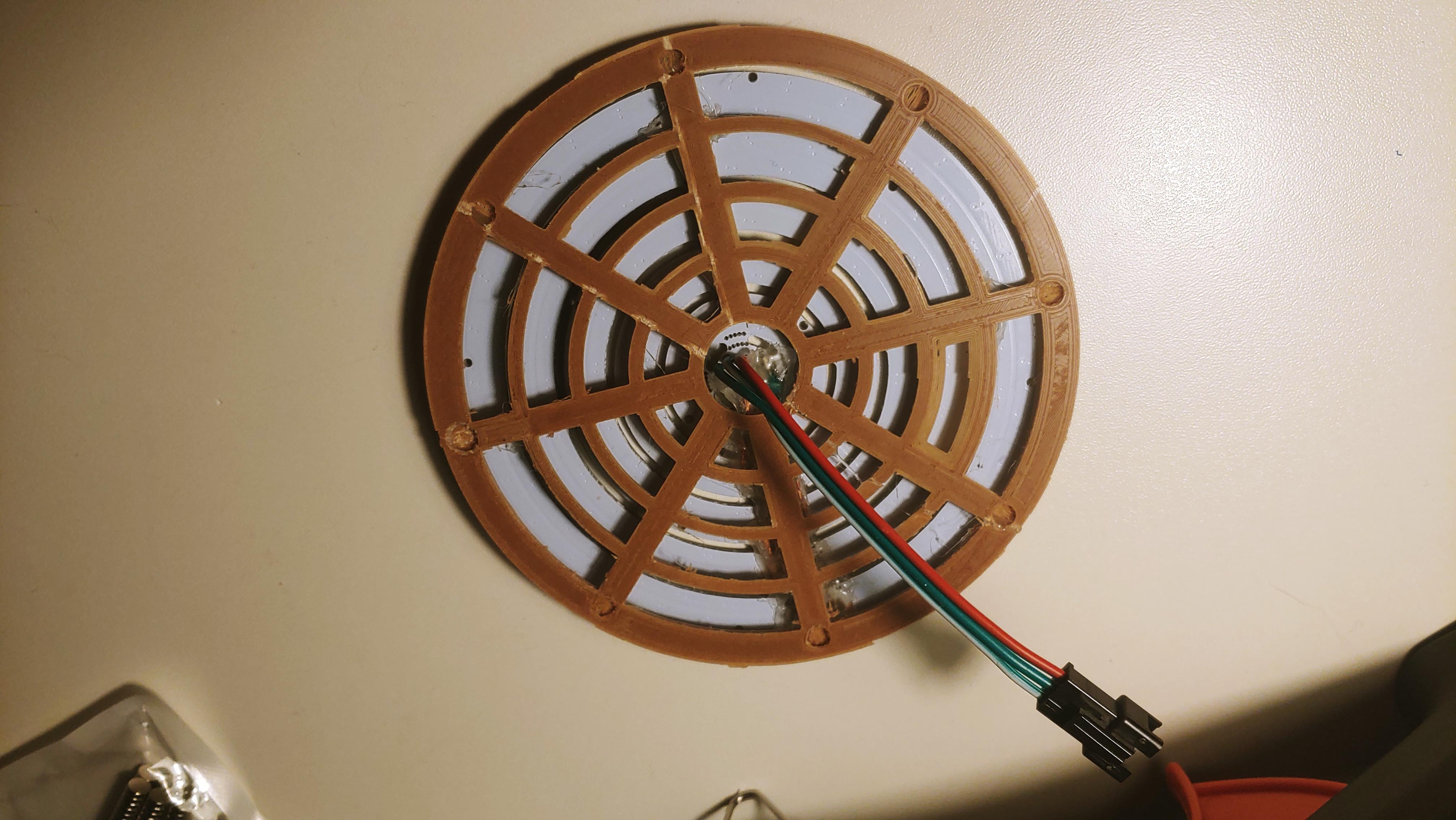
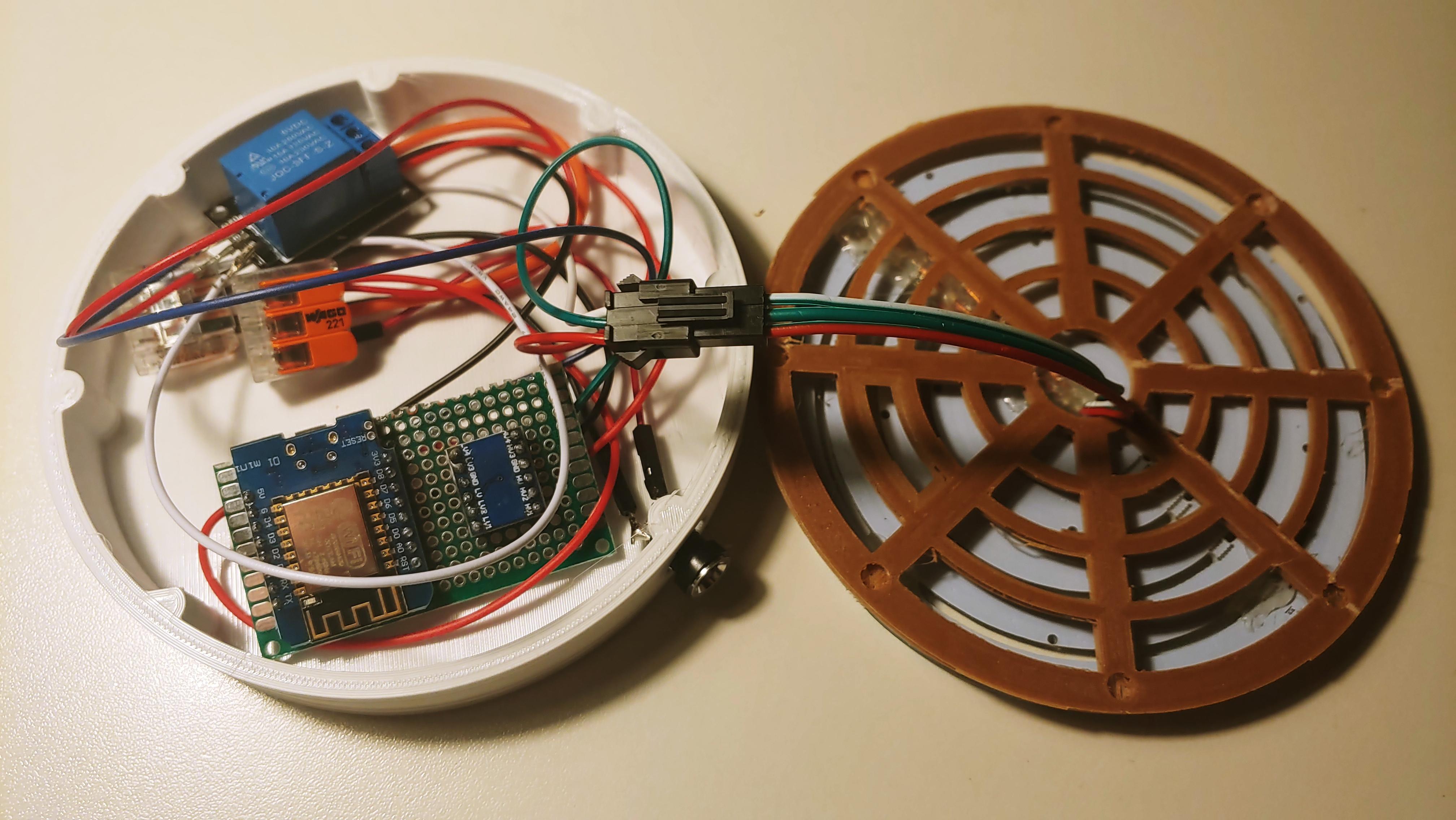
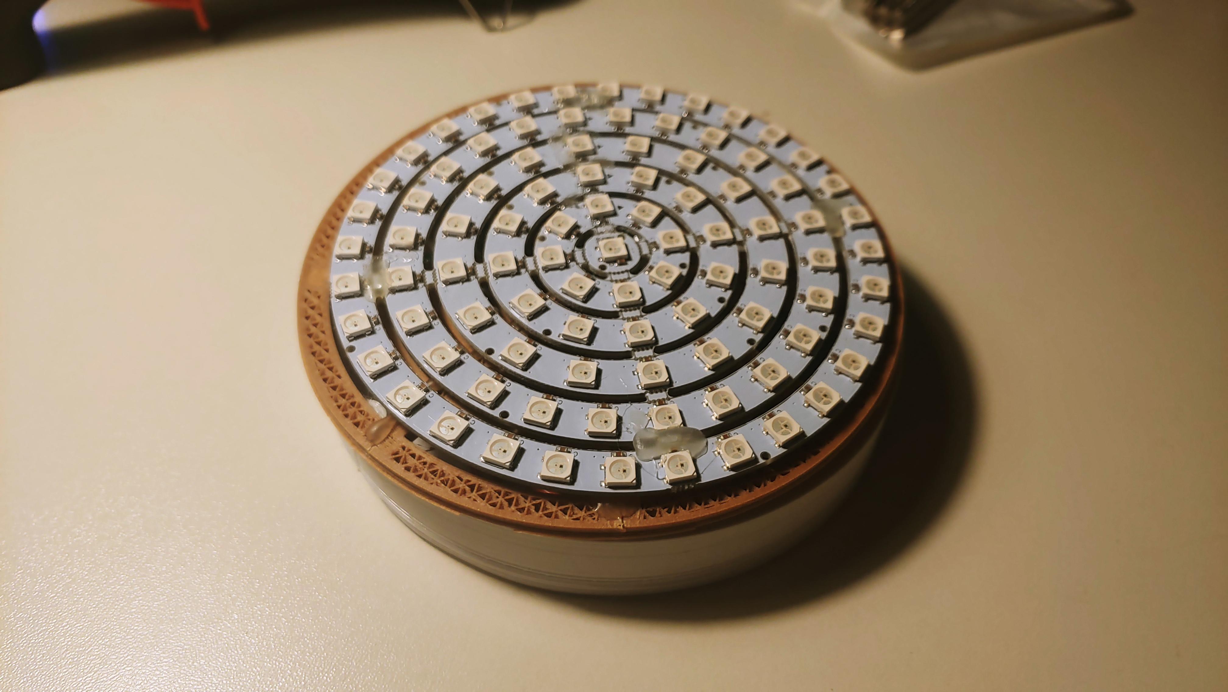
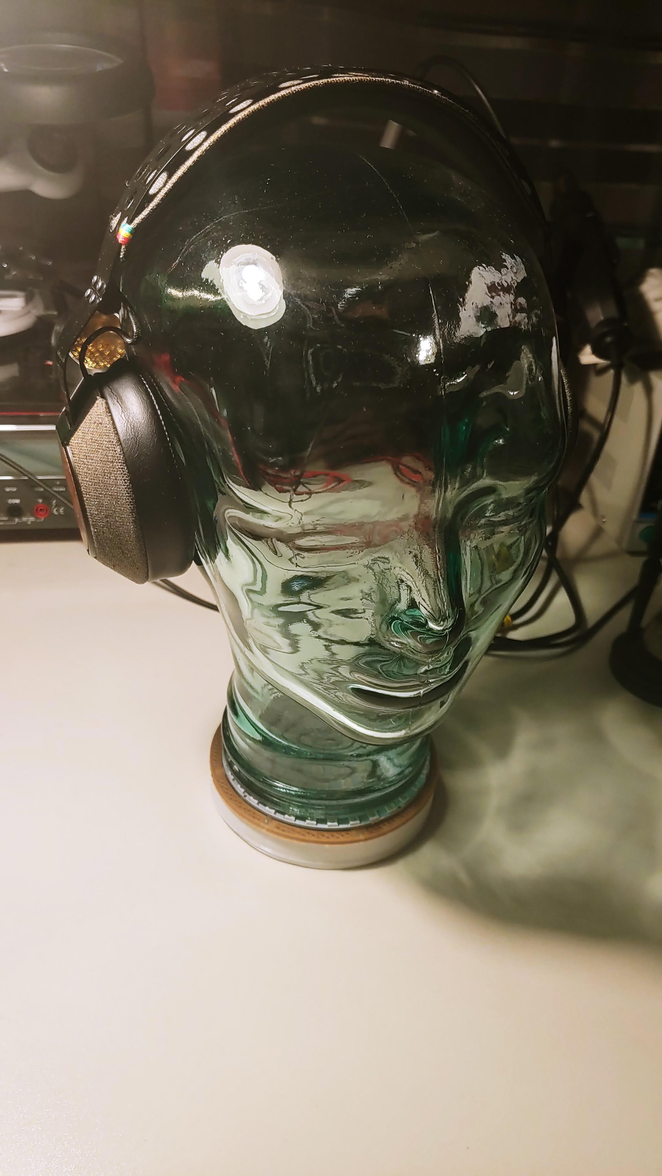
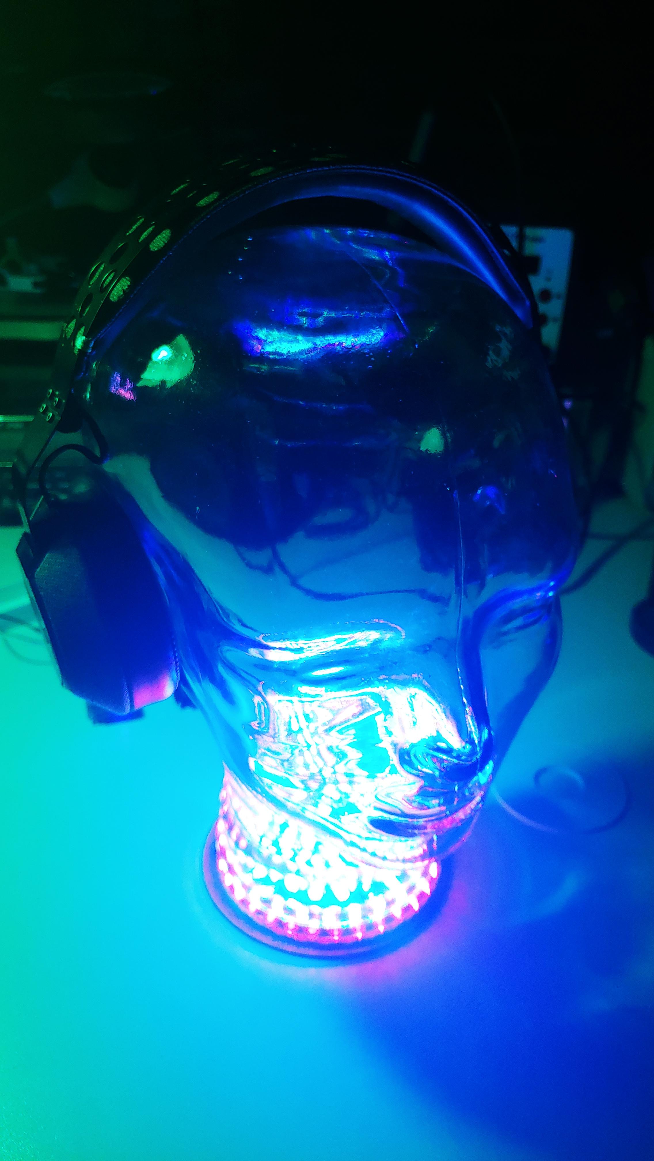
Now you can put it together!
For this glue in each of the 16 small holes of the bottom and top a magnet. The top and bottom should now fit together perfectly and stay together because of the magnets.
Next put the barrel jack in the small hole of the base and fix it in place either with glue or the provide hex nut.
Also fix the LED controller inside the base with some more glue. Now route the cable from the LEDs through the hole in the top and connect it with the LED cable from the controller.
Finally, put the top on the bottom and the glass head on the finished base.
Watch Your Headphones Glow!

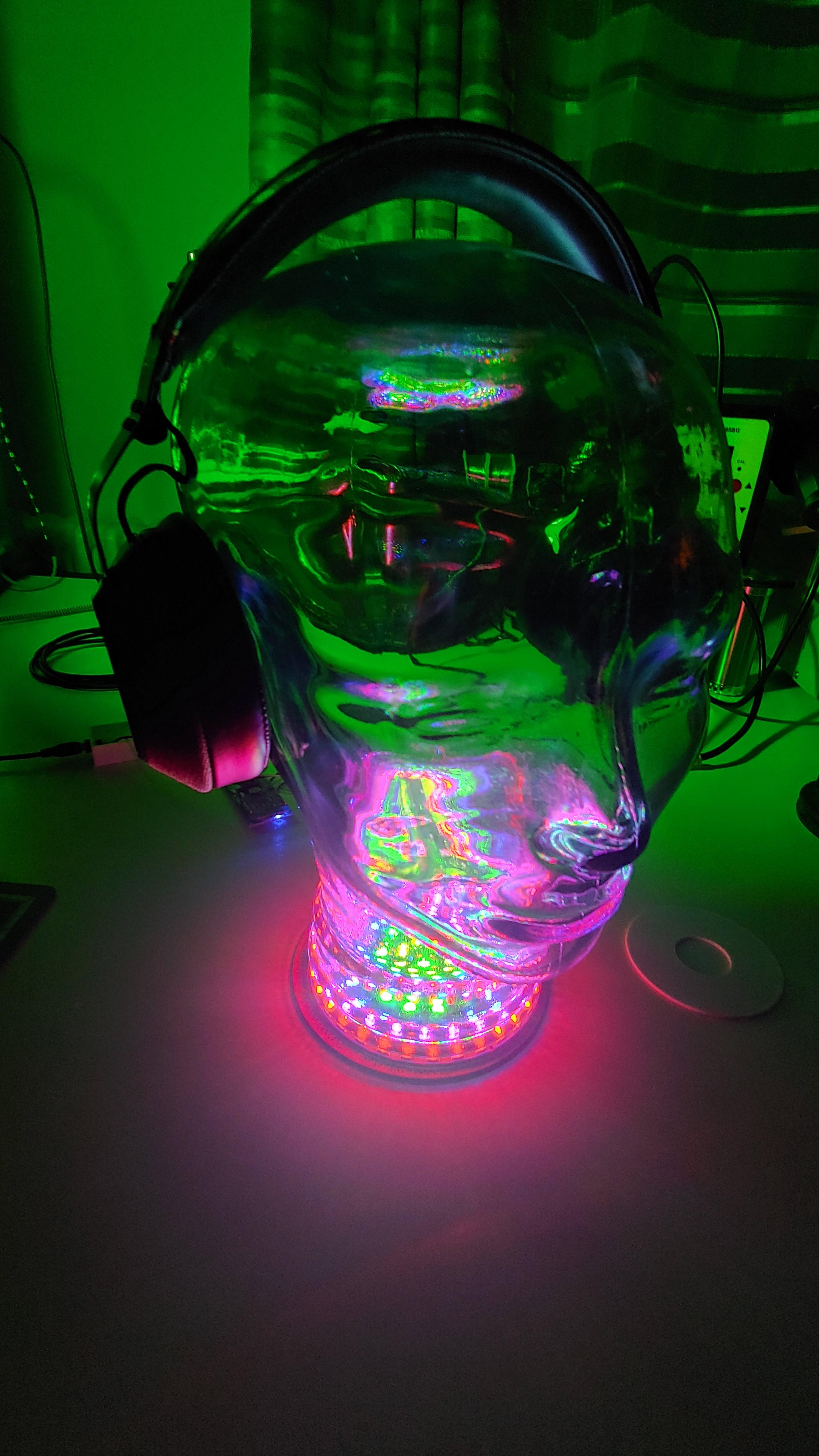
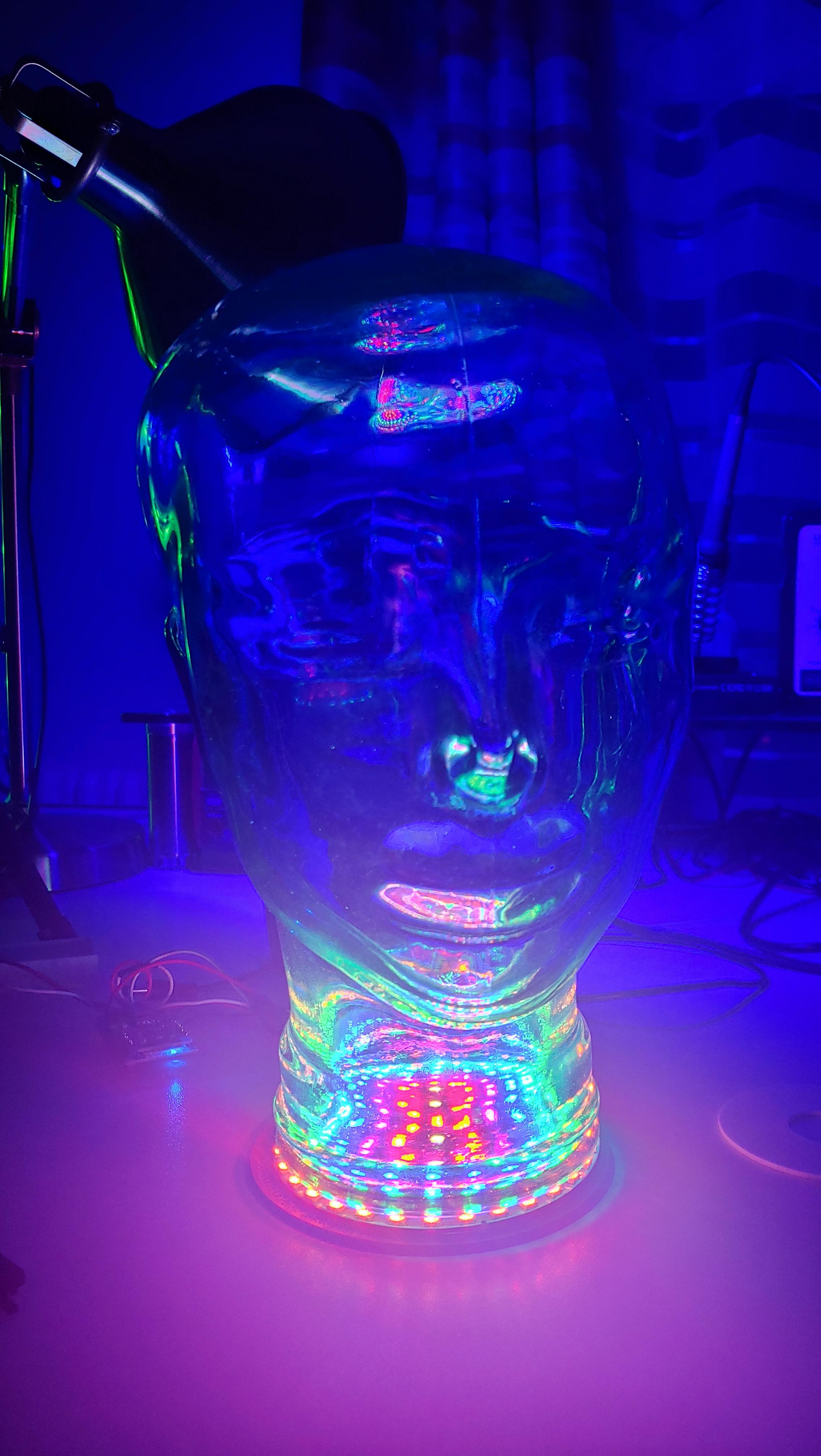
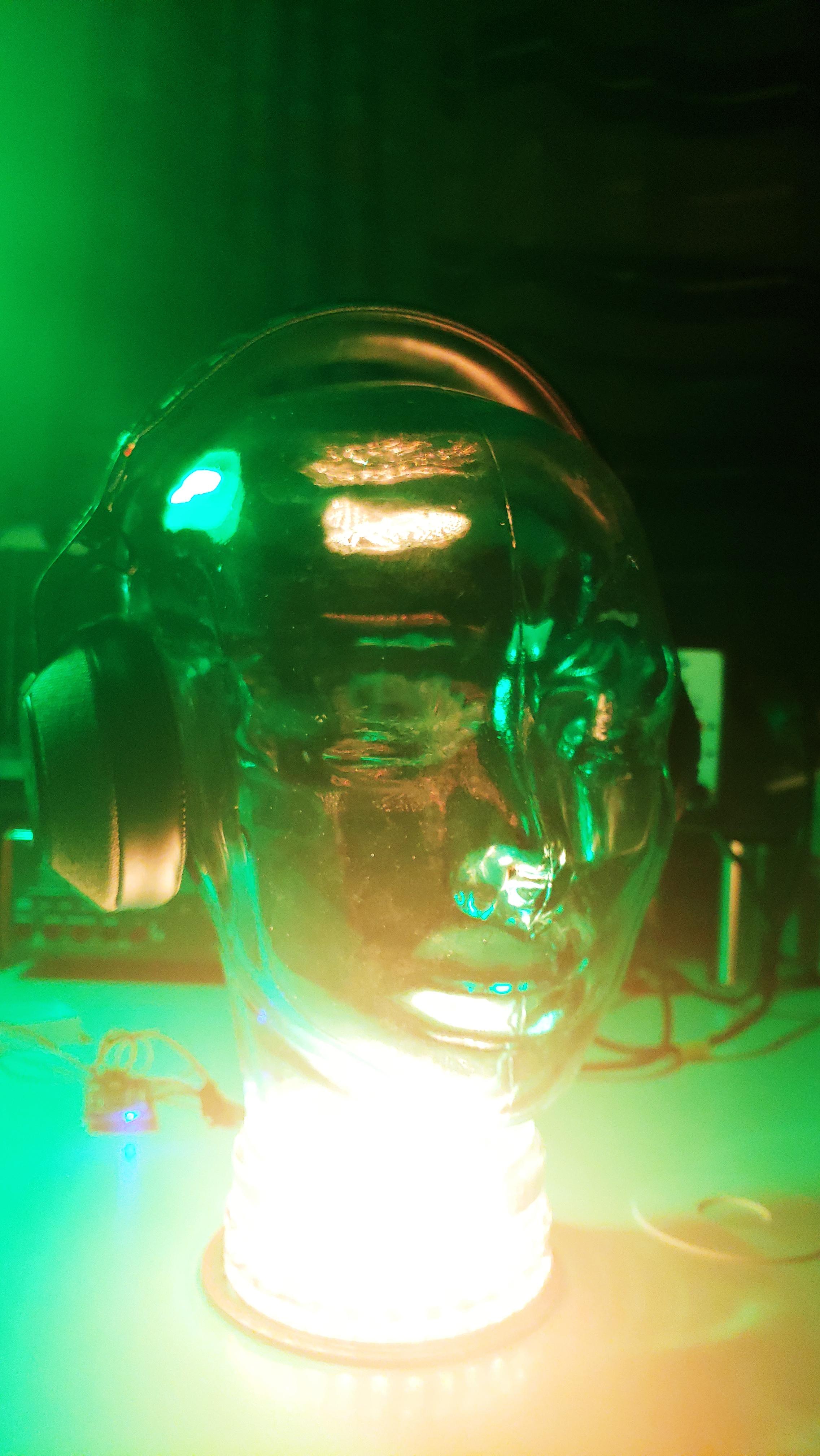

You have created your own headphone throne!
Congratulations, now all your headphones can be stored in style.