Storage and Charging Rack for Root Robots
by terbos90803 in Workshop > 3D Printing
1048 Views, 5 Favorites, 0 Comments
Storage and Charging Rack for Root Robots
.jpg)

The Root is an educational robot from iRobot frequently used in classrooms. It can be a challenge to store and charge many Roots. This storage and charging rack is a helpful way to manage a classroom set of Roots.
Due to the modular design, you can make the rack any size you want, but if you make it 7 slots long, then 2 racks fit neatly into a standard 12-gallon storage tote.
Full disclosure: I work for iRobot, but this project is neither sponsored nor endorsed by iRobot.
Disclaimer: This project involves exposed low voltage electricity and battery charging. The end user is responsible for the safe and prudent use of this device.
Supplies
Tools:
- 3D printer with a bed capacity at least 220mm x 152mm
- soldering iron and solder
- wire cutters
- long nosed pliers
- hobby knife
- hacksaw
- 1/2" drill bit (optional)
- crimping tool (optional)
Materials for 1 rack with 7 slots:
- printer filament - PETG preferred for strength
- 18ga stranded wire
- 1/2" wide adhesive copper tape
- 36" of 1/4-20 all-threaded rod
- 4x 1/4" washers
- 2x 1/4-20 standard nuts
- 2x 1/4-20 acorn nuts
- 8V 5A DC power supply with barrel connector
- panel mount barrel jack that matches the power supply
- 5A panel mount circuit breaker
- (optional) 2x 18ga crimp-on connectors that match the circuit breaker
How Big Should It Be?
.jpg)
Figure out how many total charging spaces you'd like to have.
Two racks with 7 slots each fit nicely into a standard 12-gallon storage tote.
If you want to adjust the number of slots, you need to consider the power supply and breaker.
- Power supply
- Voltage must always be 8V.
- Current rating should be more than the total needed for all the slots in the rack.
- A single Root uses about 0.7A when charging
- 7 Roots use about 4.9A when they're all charging.
- Thus, a 5A supply is sufficient for 7 slots.
- Breaker
- Select one to be the same or less than the current rating of the power supply.
The rest of this Instructable is based on a 7-slot rack.


Print the parts in the suggested orientations. The recommended settings are:
- layer height - 0.30mm
- infill - gyroid 5% (Use 10% if your printer struggles at 5%)
- brim/skirt - on if possible. The handles just fit on an Ender 3 without a skirt.
- supports - off
It's helpful to print the in-between spacer blocks 2 at a time.
One of the handles has a robot rest attached to it, so print one fewer of the regular spacer blocks. Thus, if you want 7 total spaces, then print 3 pairs of the in-between blocks and 1 each of the other parts.
The STL files for each part are included here. If you would like the source models, you may find them at:
NOTE: The STL files match the slicer images on this step. They are slightly different from the photos in the following steps. The photos are of the v1 prints which made it difficult to see the charging lights on the Roots. The v2 models add the notch in the center post.
Clean Up the Prints
.jpg)
Trim or sand any excess or rough edges off the prints.
Because the power shell was printed vertically, its side holes won't be round. Use a 1/2" drill bit to round out the two 1/2" holes in the side of the power shell. You may also do this with a hobby knife or sandpaper, but the drill is easier.
You may clean up the 1/4" holes if necessary, but they're less critical. DO NOT drill them out larger than 1/4".
Test Fit and Measure
.jpg)
Stack all the parts together and measure the distance of the solid portion between the inside of the power shell and the far end.
NOTE: the alignment bumps all point to the left in this photo. The right end has holes and the left end has the power shell.
In this photo of a 7-slot rack, it's about 15.25".
Measure and Cut the All-thread
.jpg)
.jpg)
.jpg)
.jpg)
.jpg)
.jpg)
.jpg)
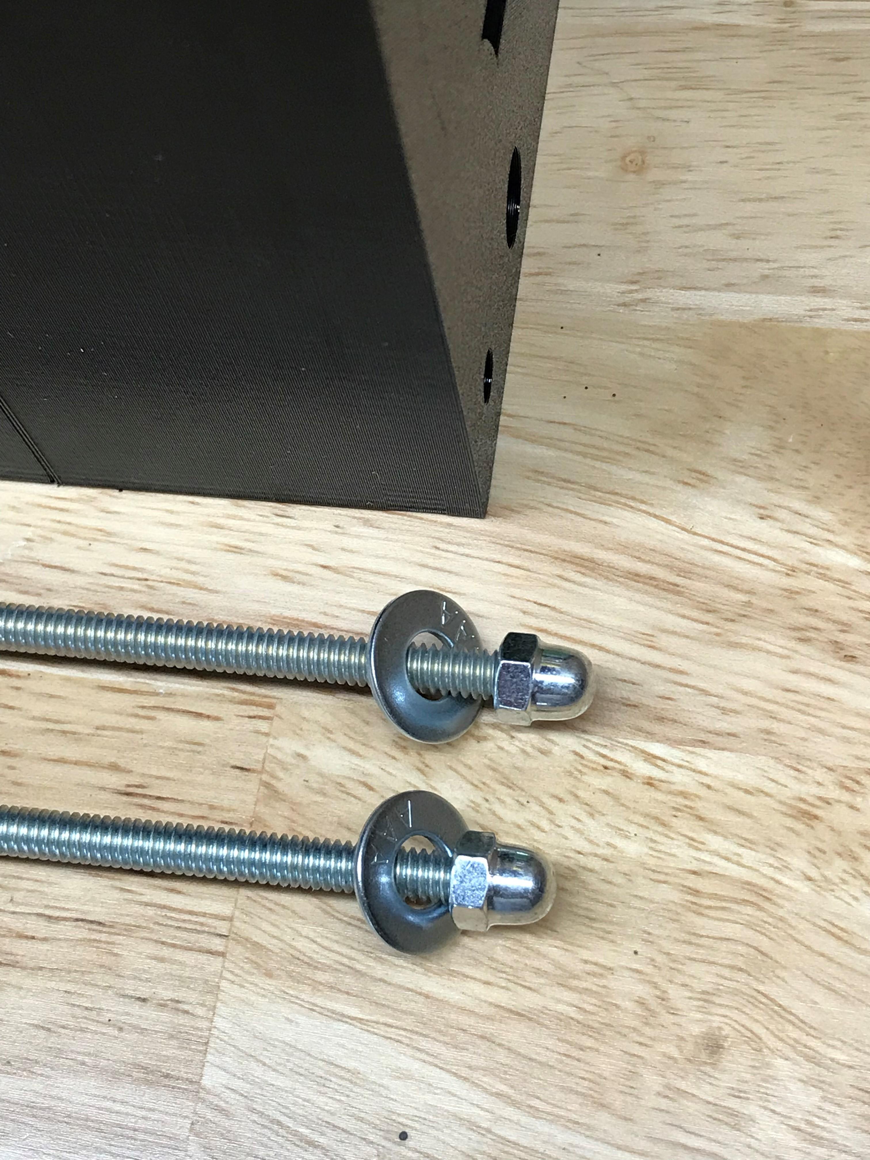
- Add a washer and acorn nut to one end of the all-thread.
- Place the washer against the right end of the stack.
- Mark the all-thread at the middle of the power shell.
- Cut the all-thread and file the end to remove burrs.
- Check the length. It should be about 3/4" longer than the stack. (About 16" for a 7-slot rack).
- Cut a second rod the same as the first.
- Add washers and acorn nuts to one end of both rods.
Prepare to Add Electronics
.jpg)
- Insert both all-thread rods through the stack with the acorn nuts on the right end (the end with holes)
- Leave off the power shell and add washers and regular nuts on the left end (the end with bumps)
- Snug up the nuts finger tight. Don't use tools.
Add Copper Tape
.jpg)
.jpg)
.jpg)
- Cut a piece of copper tape about 5-6 inches longer than the rack.
- Apply the tape into one of the slots. The best way I found to do this is to:
- Remove the backing to expose the adhesive
- Stretch the tape through the middle of both handles
- Twist the tape vertically with the sticky side facing away from the centerline of the rack
- Slide the tape into the slot with the not-sticky side touching the center posts
- At the bottom, carefully rotate the whole strip so it lays flat along the ridge
- Smooth the tape down along its length. Avoid making wrinkles.
- Leave the excess hanging off each end
- Repeat for the second slot.
Trim Copper Tape
.jpg)
.jpg)
.jpg)
.jpg)
.jpg)
- On the end with the holes and acorn nuts, trim the tape flush.
- On the end with the bumps and regular nuts, apply the tape vertically down the face.
- Be careful not to tear the tape while doing this step. If you do tear it, remove the whole strip and use a fresh one.
- Using a hobby knife, trim those tape ends above the bottom edge of the rack. Leave about 1/8" gap.
Install Panel Mount Items
.jpg)
.jpg)
.jpg)
- Test fit the circuit breaker and barrel jack into the power shell. Make adjustments if needed.
- Install the retaining ring for the circuit breaker.
- Remove the barrel jack
Wire the Barrel Jack
.jpg)
.jpg)
.jpg)
Solder about 6" of wire to the barrel jack.
I used 18ga red-black wire, but the colors don't matter. You may use the same color of single stranded wire for everything if you want. Roots will use any polarity.
Install the Barrel Jack
.jpg)
.jpg)
.jpg)
- Thread the wire through the hole and seat the barrel jack
- Install the washer and nut on the back side of the barrel jack
- Snug the nut down with long nosed pliers
Wire the Circuit Breaker
.jpg)
.jpg)
.jpg)
.jpg)
- Separate paired wires if necessary.
- Cut one wire to just long enough to reach the breaker.
- Add a connector and attach to the breaker.
- Alternately, solder the wire directly to the breaker.
- Add a second connector to the offcut from the first wire and attach it to the breaker.
- Alternately, solder the wire directly to the breaker.
- Strip and tin the loose ends of both wires.
- Position the wires roughly as shown.
Final Connections
.jpg)
.jpg)
- Add a dot of solder to each of the copper tape strips.
- Position the power shell as shown and solder both wires to the strips.
Close It Up
.jpg)
.jpg)
.jpg)
- Remove the nuts and washers from this end. (Do not remove the all-thread or the acorn nuts)
- Install the power shell.
- Replace the washers and nuts inside the power shell.
- Snug them up by hand and gently tighten with pliers. No more than 1/4 turn past hand tight.
Load It Up
.jpg)
.jpg)
Your Root charging rack is now complete.
Attach the power supply and drop Roots into the charging slots. Polarity doesn't matter, but the Roots stack better if they're all facing the same direction.
Safe Charging
.jpg)

- The Roots are charging normally when you can see the glowing light on their top just below the pen holder.
- It's normal for the color sensor on the bottom to flicker (or not) during charging. Avoid exposing flickering lights to photosensitive individuals.
- The Roots will stop charging automatically when they're full.
- As with any chargeable device, it's best practice to not leave them plugged in after they're fully charged. It is ok to leave them in the unpowered rack.
- The exposed copper strips on the charger have 8V DC on them when powered. This will not cause injury under normal circumstances.
- Do not intentionally place metal or cause a short across the copper strips. The breaker is only intended as a backup.