Stepper Motor Control X Bluetooth and App
by CarlosVoltT in Circuits > Arduino
242 Views, 3 Favorites, 0 Comments
Stepper Motor Control X Bluetooth and App
.png)
In this tutorial we will see a circuit, which controls a stepper motor, with an application made in app inventor, using bluetooth, and the hc-05 module and arduino.
In this tutorial we will see a circuit, which controls a stepper motor, with an application made in app inventor, using bluetooth, and the hc-05 module and arduino.
Electronic components
Arduino mini pro
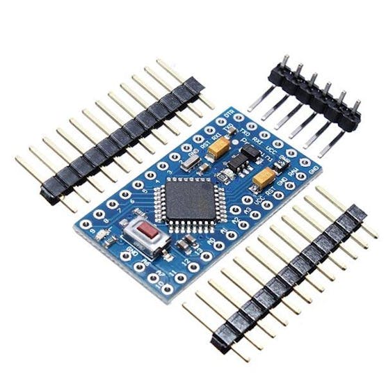
The Arduino Pro Mini is a microcontroller board based on the ATmega328 .
It has 14 digital input/output pins (of which 6 can be used as PWM outputs), 6 analog inputs, an integrated resonator, a reset button, and holes for mounting pin headers. A six-pin header can be connected to an FTDI cable or a Sparkfun breakout board to provide USB power and communication to the board.
The Arduino Pro Mini is designed for semi-permanent installation on objects or exhibits. The board comes without pre-mounted headers, allowing the use of various types of connectors or direct soldering of wires. The pin layout is compatible with the Arduino Mini.
There are two versions of the Pro Mini. One runs at 3.3V and 8 MHz, the other at 5V and 16 MHz.
hc-05 modules
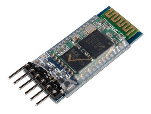
- Works as a bluetooth master and slave device
- Configurable via AT commands
- Bluetooth V2.0+EDR
- Operating frequency: 2.4 GHz ISM band
- Modulation: GFSK (Gaussian Frequency Shift Keying)
- Transmit power: <=4dBm, Class 2
- Sensitivity: <=-84dBm @ 0.1% BER
- Security: Authentication and encryption
- Bluetooth profiles: Bluetooth serial port.
- Distance of up to 10 meters in optimal conditions
- Operating Voltage: 3.6 VDC to 6 VDC
- Current Consumption: 30 mA to 50 mA
- Chip: BC417143
- Version or firmware: 3.0-20170609
- Default Baud: 38400
- Supported baud rates: 1200, 2400, 4800, 9600, 19200, 38400, 57600, 115200.
- Interface: Serial TTL
- Antenna: Integrated into the PCB
- Security: Authentication and encryption (Default password: 0000 or 1234)
- Working temperature (Max): 75°C
- Working temperature (Min): -20°C
- Dimensions: 4.4 x 1.6 x 0.7 cm
Stepper motor 28BYJ-48
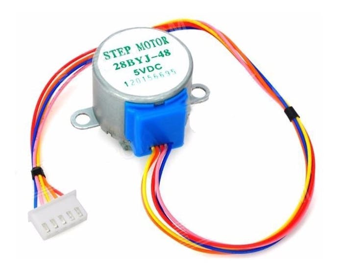
The parameters of this stepper motor are:
- Model: 28BYJ-48 – 5V
- Nominal voltage: 5V (or 12V, value indicated on the back).
- Number of phases: 4.
- Speed reducer: 1/64
- Step angle: 5.625° / 64
- Frequency: 100Hz
- DC resistance: 50Ω ±7% (25°C)
- Frequency with traction: > 600Hz
- Non-traction frequency: > 1000Hz
- Traction torque: >34.3mN.m (120Hz)
- Self-positioning torque: >34.3mN.m
- Torque with friction: 600-1200 gf.cm
- Torque drag: 300 gf.cm
- Insulation resistance > 10MΩ (500V)
- Electrical insulation: 600VAC/1mA/1s
- Insulation grade: A
- Temperature rise: < 40K (120Hz)
- Noise: < 35dB (120Hz, no load, 10cm)
ULN2003APG
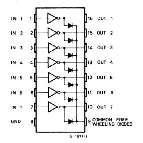
Main specifications:
- 500 mA nominal collector current (single output)
- 50V output (there is a version that supports 100V output)
- Includes output flyback diodes
- TTL and 5-V CMOS logic compatible inputs
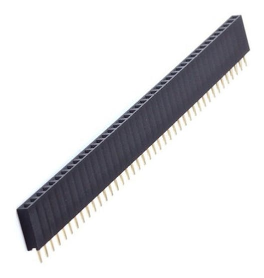
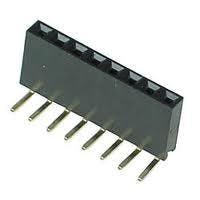
Female pins
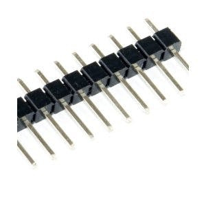
Male pins
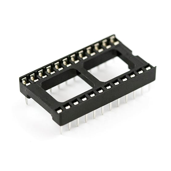
A socket for arduino mini pro
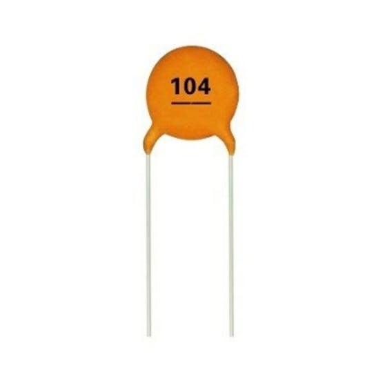
A 100 nF ceramic disc capacitor
90 degree female pins
PCB
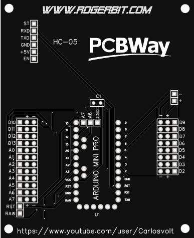
Download gerber file –> pcb stepper motor bluetooth
Application
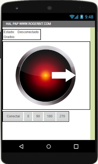
Download app and source file app inventor–> app bluetooth stepper motor
#define pin2  2

#define pin3  3

#define pin4  4

#define pin5  5

#define retardo 2

char caracter;

String cadena;

float pasos = 0;

int datos_serial = 0;

void setup() {

  pinMode(pin2, OUTPUT);

  pinMode(pin3, OUTPUT);

  pinMode(pin4, OUTPUT);

  pinMode(pin5, OUTPUT);

  Serial.begin(57600); //Velocidad del módulo bluetooth

}

void loop() {

  while (Serial.available()) {

    delay(3);

    char c = Serial.read();

    cadena += c;

  }


  if (cadena.length() >0) {


   Serial.println(cadena.toInt());

    datos_serial = cadena.toInt();


  }

  while(datos_serial>pasos){


         atras();

         delayMicroseconds(40);

         pasos = pasos + 1;


  }

 while(datos_serial<pasos){


          adelante();

          delayMicroseconds(40);

          pasos = pasos - 1;


  }


  if (cadena == "SET"){

    pasos = 0;

    datos_serial = 0;

    }


  cadena="";

}

void paso1(){

  digitalWrite(pin2, HIGH);

  digitalWrite(pin3, HIGH);

  digitalWrite(pin4, LOW);

  digitalWrite(pin5, LOW);

}

void paso2(){

  digitalWrite(pin2, LOW);

  digitalWrite(pin3, HIGH);

  digitalWrite(pin4, HIGH);

  digitalWrite(pin5, LOW);

}

void paso3(){

  digitalWrite(pin2, LOW);

  digitalWrite(pin3, LOW);

  digitalWrite(pin4, HIGH);

  digitalWrite(pin5, HIGH);

}

void paso4(){

  digitalWrite(pin2, HIGH);

  digitalWrite(pin3, LOW);

  digitalWrite(pin4, LOW);

  digitalWrite(pin5, HIGH);

}

void pasoApagado(){

  digitalWrite(pin2, LOW);

  digitalWrite(pin3, LOW);

  digitalWrite(pin4, LOW);

  digitalWrite(pin5, LOW);

}

void adelante(){

  paso1();

  delay(retardo);

  paso2();

  delay(retardo);

  paso3();

  delay(retardo);

  paso4();

  delay(retardo);

}

void atras(){

  paso3();

  delay(retardo);

  paso2();

  delay(retardo);

  paso1();

  delay(retardo);

  paso4();

  delay(retardo);

}