Stellating 3D Models in Inventor
by rotormind in Design > Software
4250 Views, 12 Favorites, 0 Comments
Stellating 3D Models in Inventor

In my last Instructable, I showed how to construct polyhedra and their duals in Autodesk Inventor without any math. Unfortunately Inventor's constraint system breaks down when it comes to the 20-sided icosahedron, the most complicated of the Platonic solids.
Here we're going to make an icosahedron with only a teeny bit of math, using a neat geometric trick based on the Golden Ratio. The trick here is to use three rectangles that intersect at right angles -- a natural match for Inventor's Euclidean basis planes. It turns out that if these rectangles are "golden rectangles" and centered on each other, their 12 corners are the vertices of an icosahedron!
Making and Scaling a Golden Rectangle
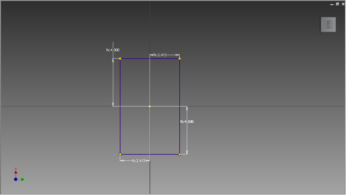
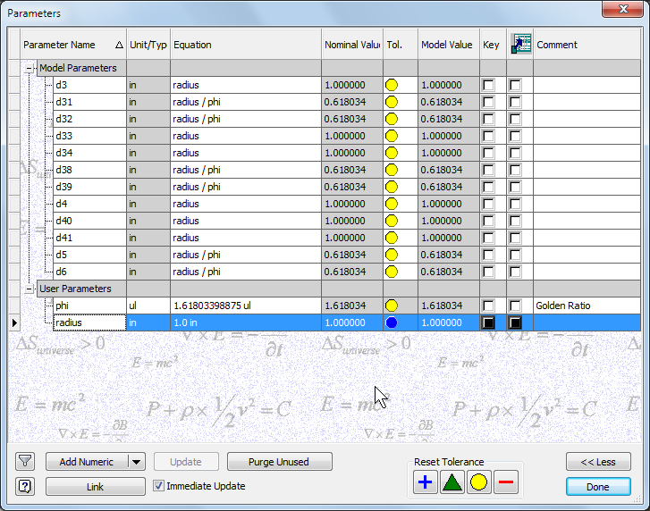
So the first thing you want to do is to make a golden rectangle: this is a rectangle with the ratio 1:φ, where φ is the Golden ratio φ = 1.6180339887498948482...
Because we want to be able to change the size of the icosahedron, we want to make our three rectangles the same size and proportional to the longest edge, which is roughly the "diameter" of the icosahedron. So we will set the rectangle dimensions to the user parameters "radius" and "radius/phi" (choose ℱx from the mini-menubar). This gives us a rectangle with dimensions 2*radius by 2*radius/φ; if we change the user parameter "radius" all the rectangles, and thus our icosahedron, will scale along with it, and the rectangles will remain in the proper proportion.
Finishing the Rectangles
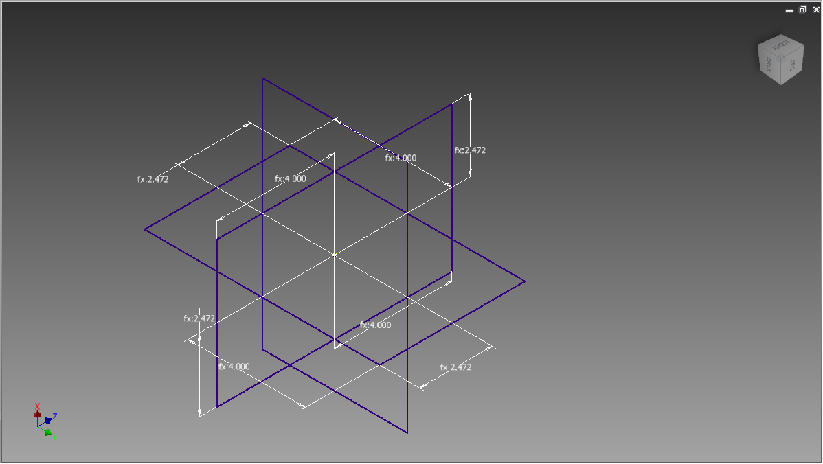
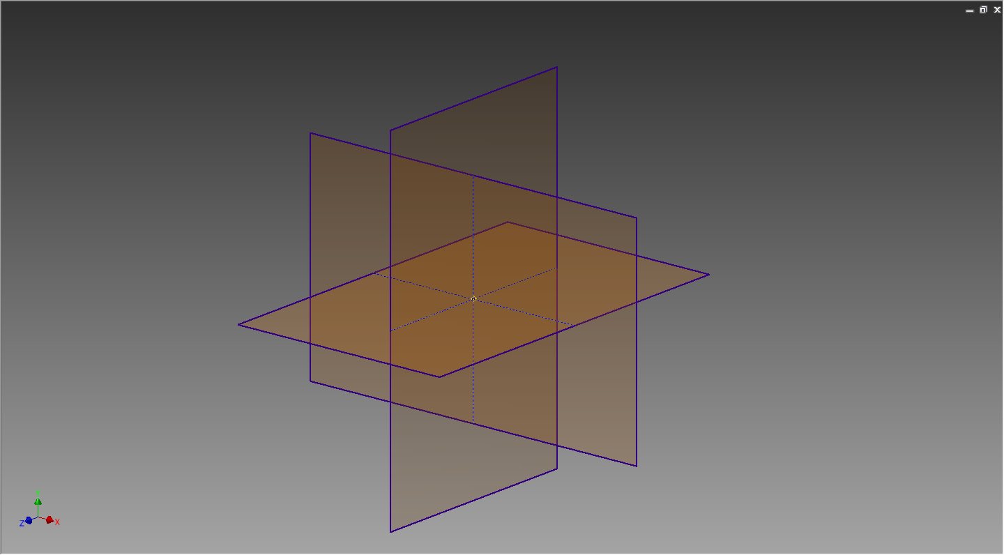
So once you have created the rectangle on one coordinate plane (say xy), make two more rectangles with the same dimensions on the other two coordinate planes (yz and xz). Note that there is only one way to make a rectangle on a plane so the edges don't intersect the rectangles in the other planes: do it that way! Also be sure to Project the origin onto all of your rectangles so everything stays centered and aligned when we change the rectangle size.
Making the Icosahedral Edges
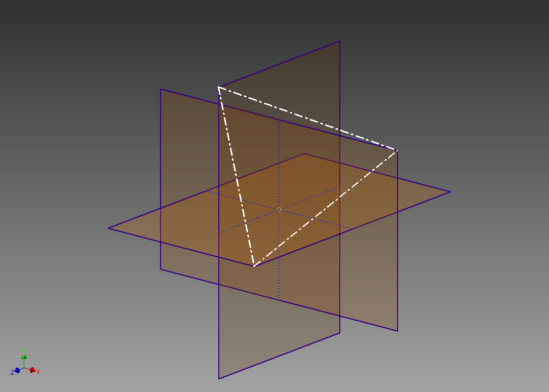
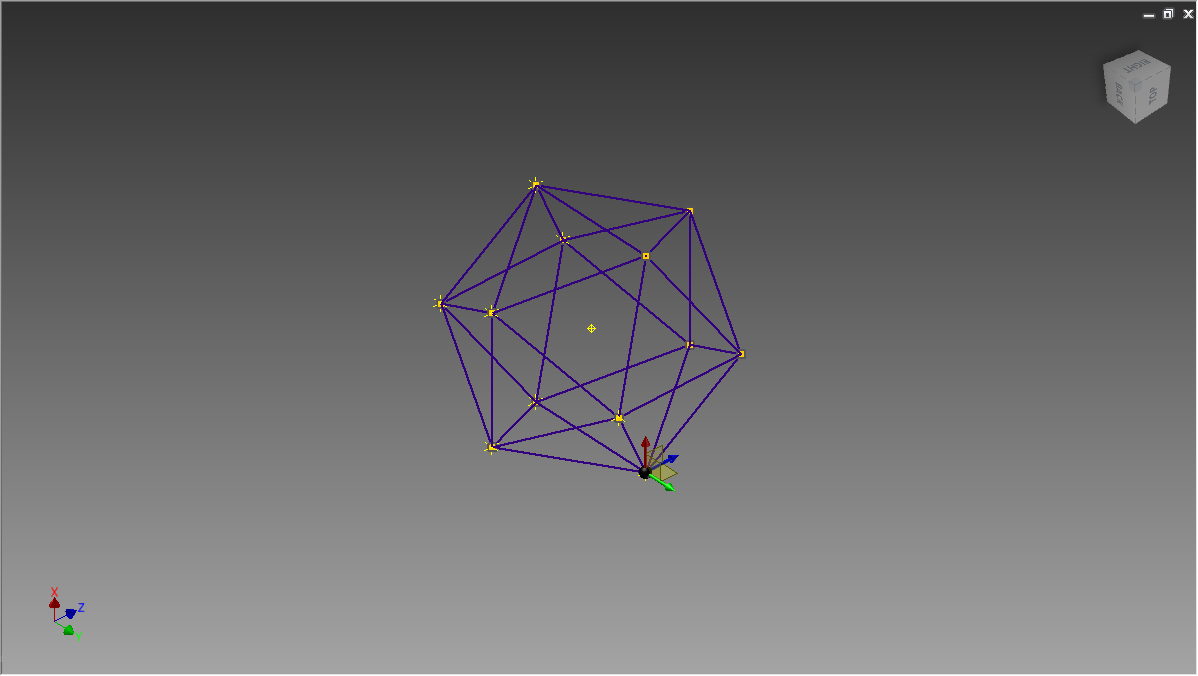
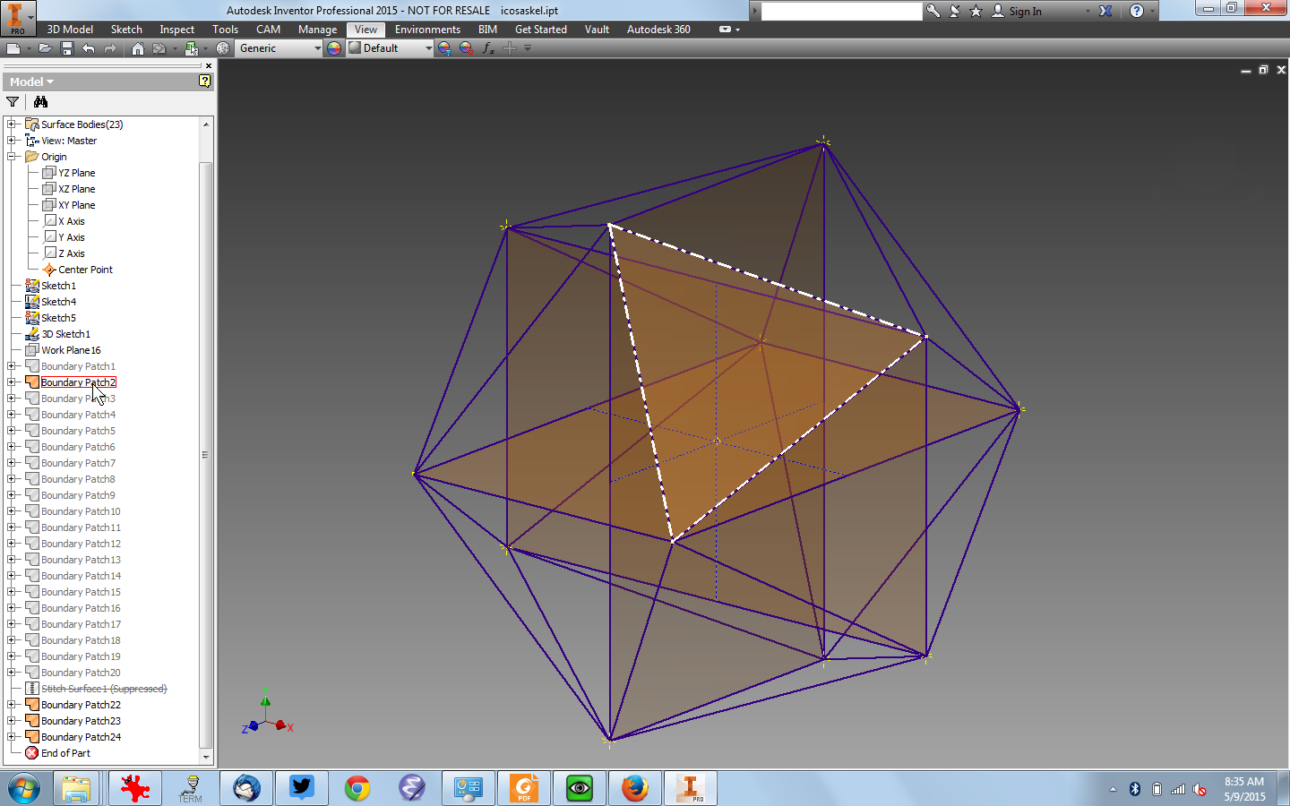
Though it may not look like it, the four corners of the three planes give you all twelve vertex (corner points) for the icosahedron. Start an new 3D sketch, and add lines between all the corners: a icosahedral side will be an equilateral triangle, and each corner point will have five neighbors. If you goof and connect across the icosahedron it's OK, just delete the line you connected.
Making the Icosahedral Surface
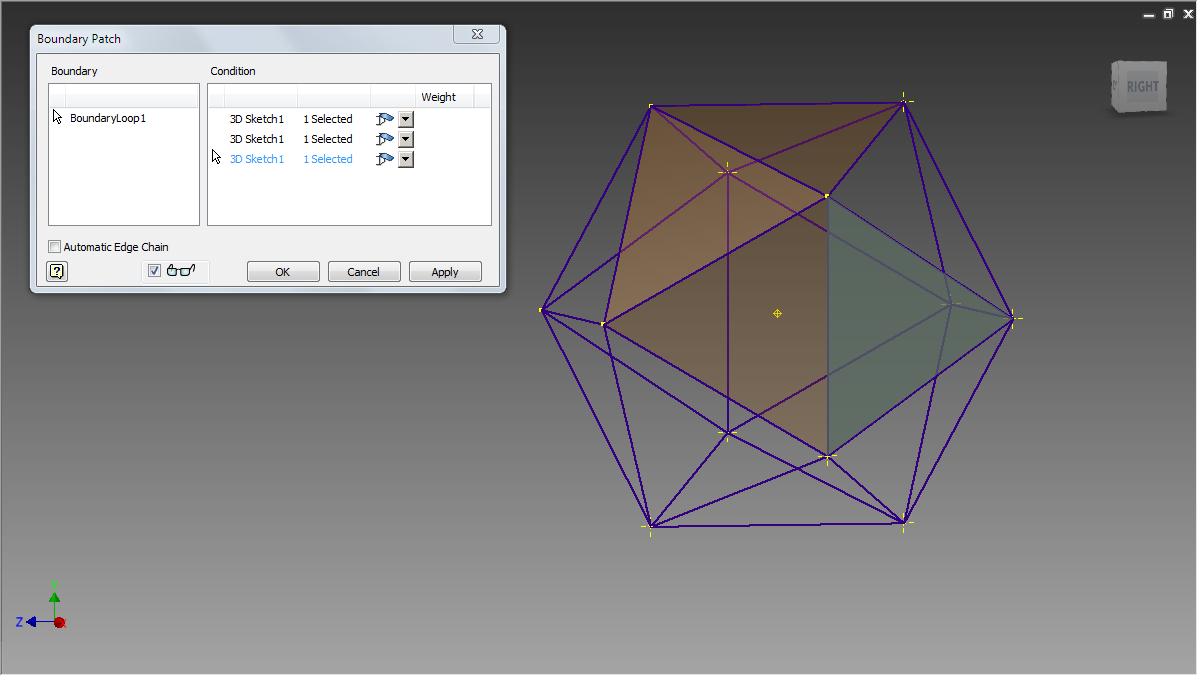
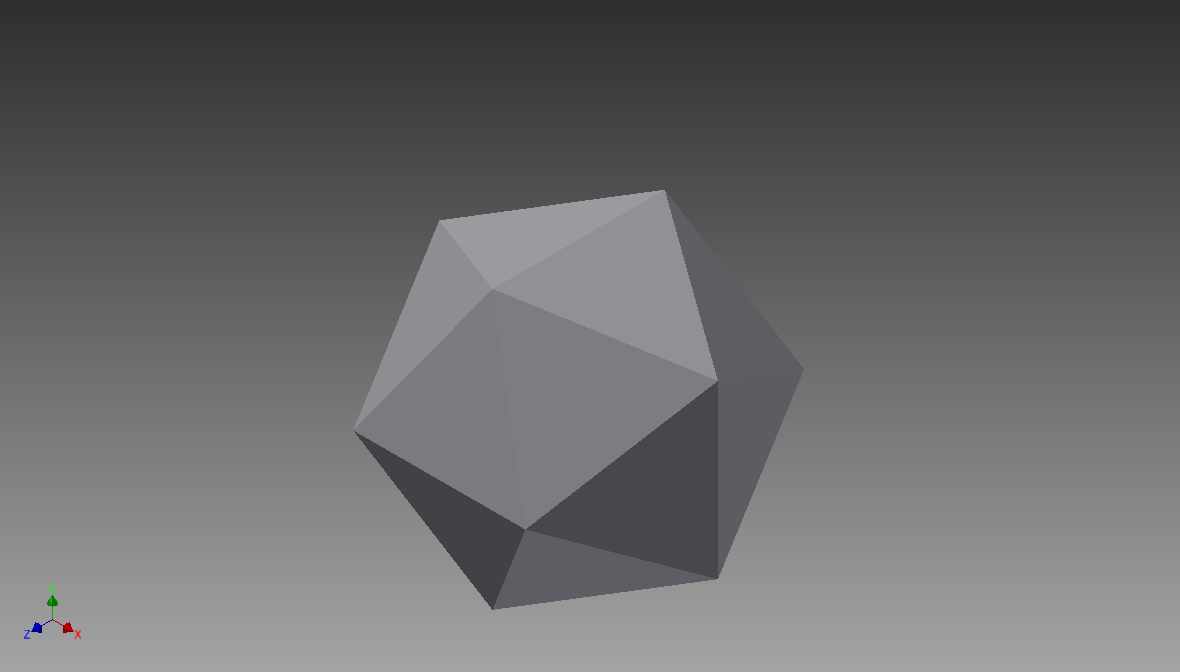
Once you have the edges in a 3D sketch, you can build the surface. Select Patch from the 3D Model menu, and select three edges of a face to form a Patch for that face (unchecking the "Automatic Edge Chain" box makes that a little easier). Do that for all twenty faces; you will need to rotate around your model, and it's probably a good idea to turn off the visibility of your golden rectangle sketches.
Once you have all the face Patches created, you can Stitch them together into a solid by choosing Stitch from the 3D Model menu. Select all your Patches and click "OK" to stitch them into a solid.
Making a Generic Face
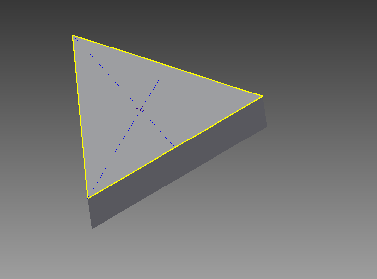
Once you have your icosahedral solid, you can make a face. This is a triangular-shaped solid that we will save as a part .ipt file. We will assemble an icosahedron out of twenty duplicates of this part; any changes we make to the part will be replicated icosahedrally, so we can make some crazy stellations as you will see.
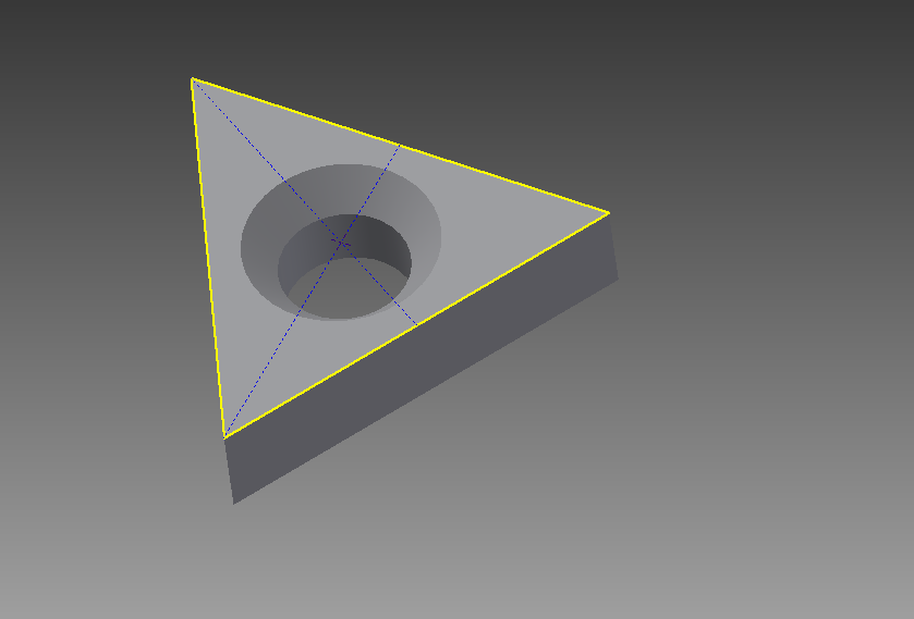
Start with a new Assembly, and Place Grounded your icosahedral solid you made. Start a new Part (.ipt), and start a 2D sketch on any face then Project Geometry the three side of the face onto the sketch. You can then Extrude that triangle into a solid face. I will suggest using the same trick to put a countersunk hole into the face so you can tell which side is out (it matters!). Drop a point at the intersection of some perpendicular construction lines if you want the hole centered (it may not matter).
Assemble the Faces
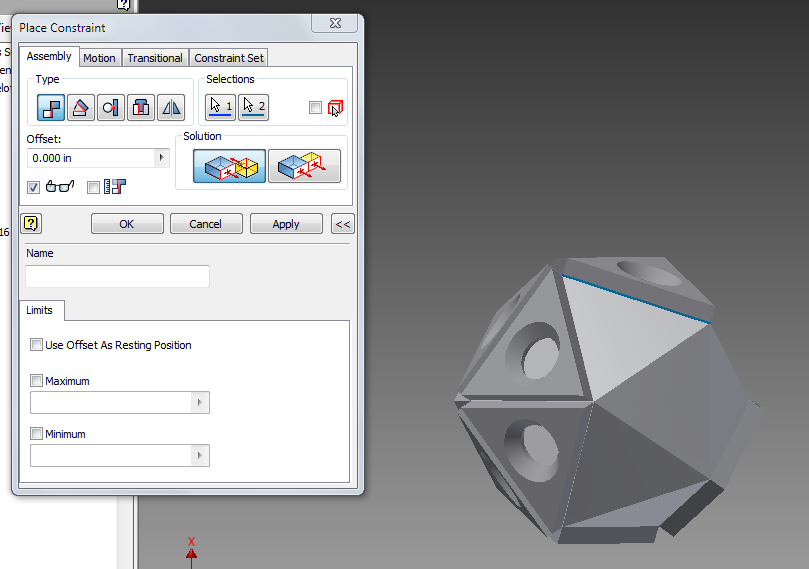
Go back to your assembly, and using the icosahedral sketch (or solid) as a skeleton, Place 20 faces and Constrain them to edges in the skeleton. You only need to Constrain two edges but you can do them all if you are a completist.
STELLAAAAAATE!
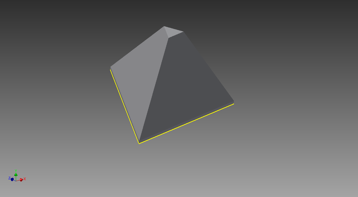
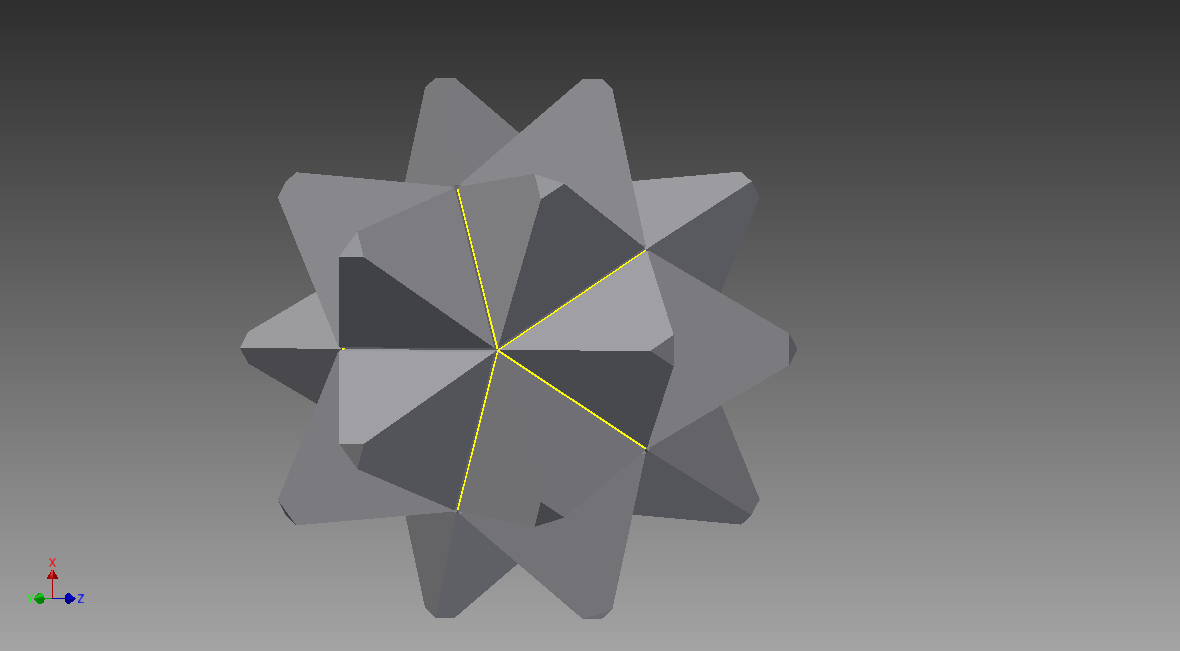
OK, here comes the cool part that justfies all the work: any changes you make to the face part gets copied with icosahedral symmetry in the Assembly! For example, let's Extrude the triangle face a little deeper, then Chamfer it into a pyramid. The assembly turns into a "stellated" icosahedron, which is pretty cool!
Stellating Sutro Tower
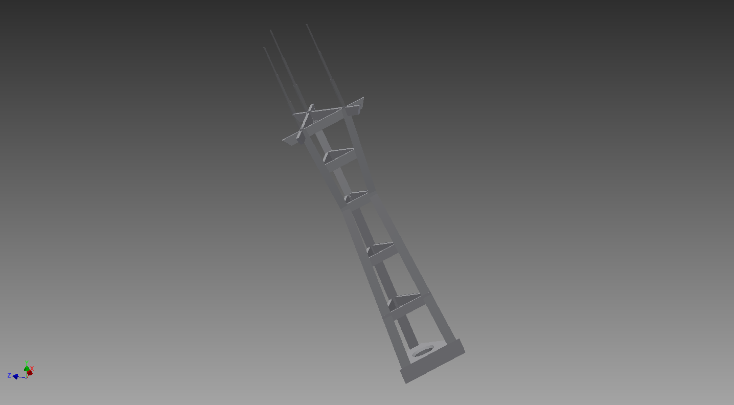
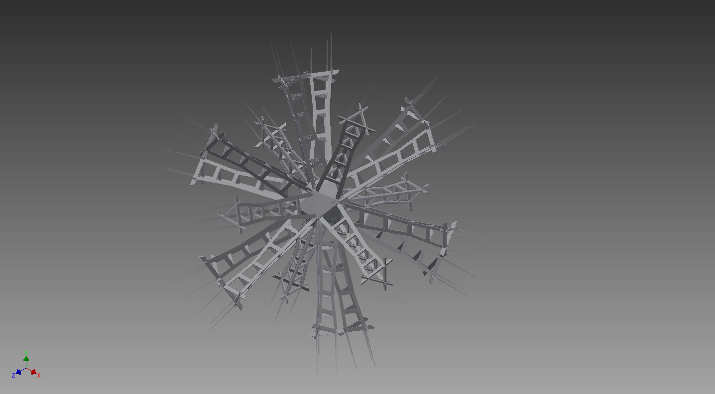
So as an example of the wild geometry you can do with this, I noticed that San Francisco's Sutro Tower is a tripod, and sits neatly on the triangular face of an icosahedron. I found a 3D model of Sutro Tower on Thingiverse, and stellated it by importing it into the triangular face part and aligning the base.
This is where I would share the STL but Inventor refuses to export the parts that were derived from the mesh, so sorry about that!
Downloads
Stellating CODAME Hoodie Person
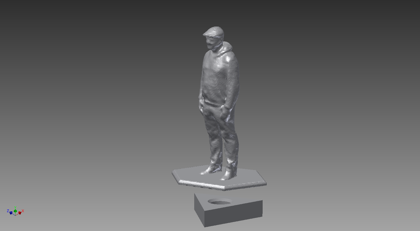
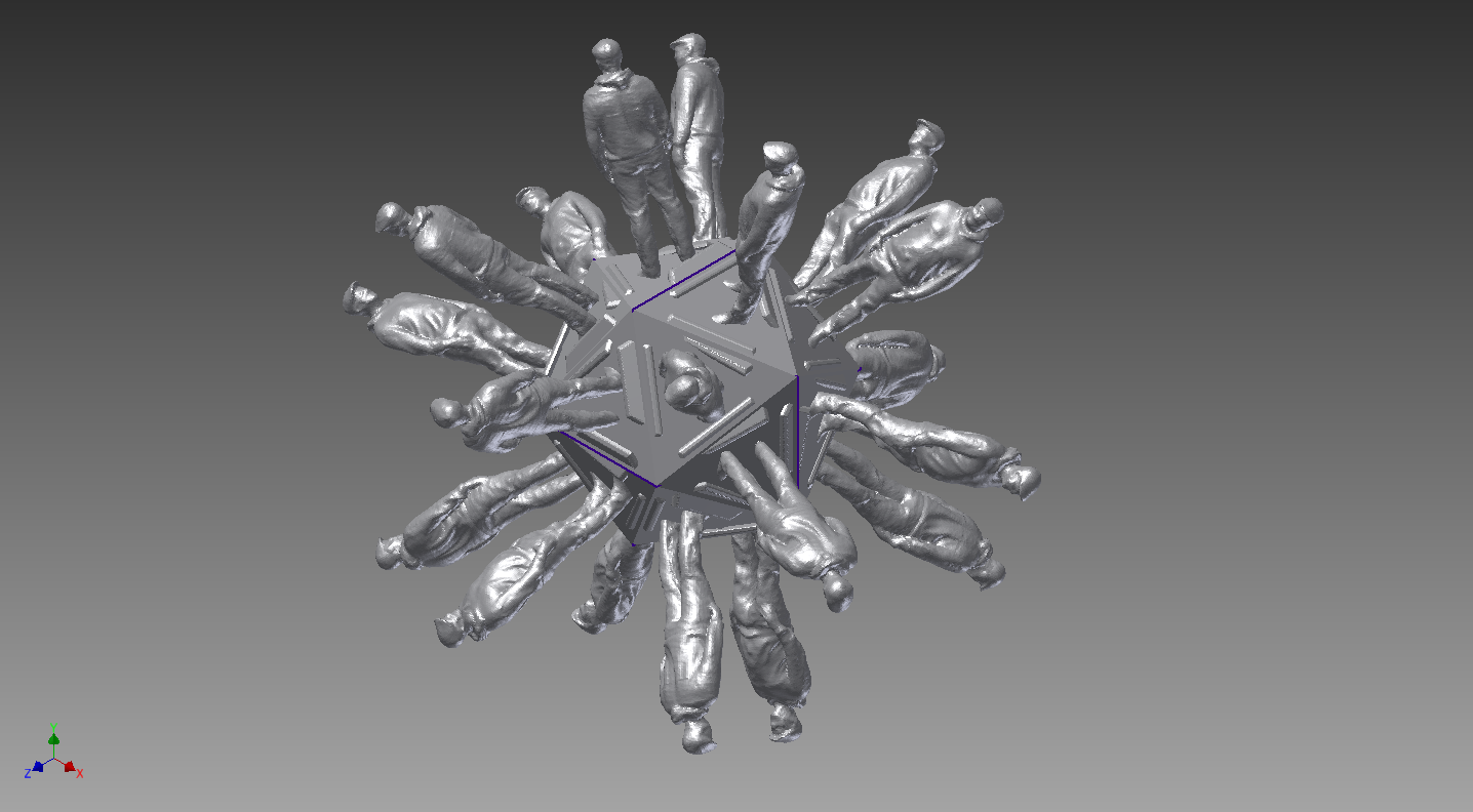
Here's another example, where I grabbed a 3D model of hoodie person by ModBod3D from the CODAME asset jam and stellated them. I stood the model some ways above the icosahedral face so the bases would kind of tile.
This, unfortunately, shows the limits of Inventor when it comes to meshes. Not only does it fail to export any mesh-derived geometry to the STL, but there's no way to clip the bases so the model stands on a plain icosahedron. Finally this Assembly even breaks Autodesk Showcase so I couldn't even get a decent rendering. So as far as meshes and Inventor: I think it's (╯°□°)╯︵ ┻━┻ time for me.