Standalone Arduino 3.3V W/ External 8 MHz Clock Being Programmed From Arduino Uno Through ICSP / ISP (with Serial Monitoring!)
by Habino in Circuits > Arduino
1162 Views, 5 Favorites, 0 Comments
Standalone Arduino 3.3V W/ External 8 MHz Clock Being Programmed From Arduino Uno Through ICSP / ISP (with Serial Monitoring!)
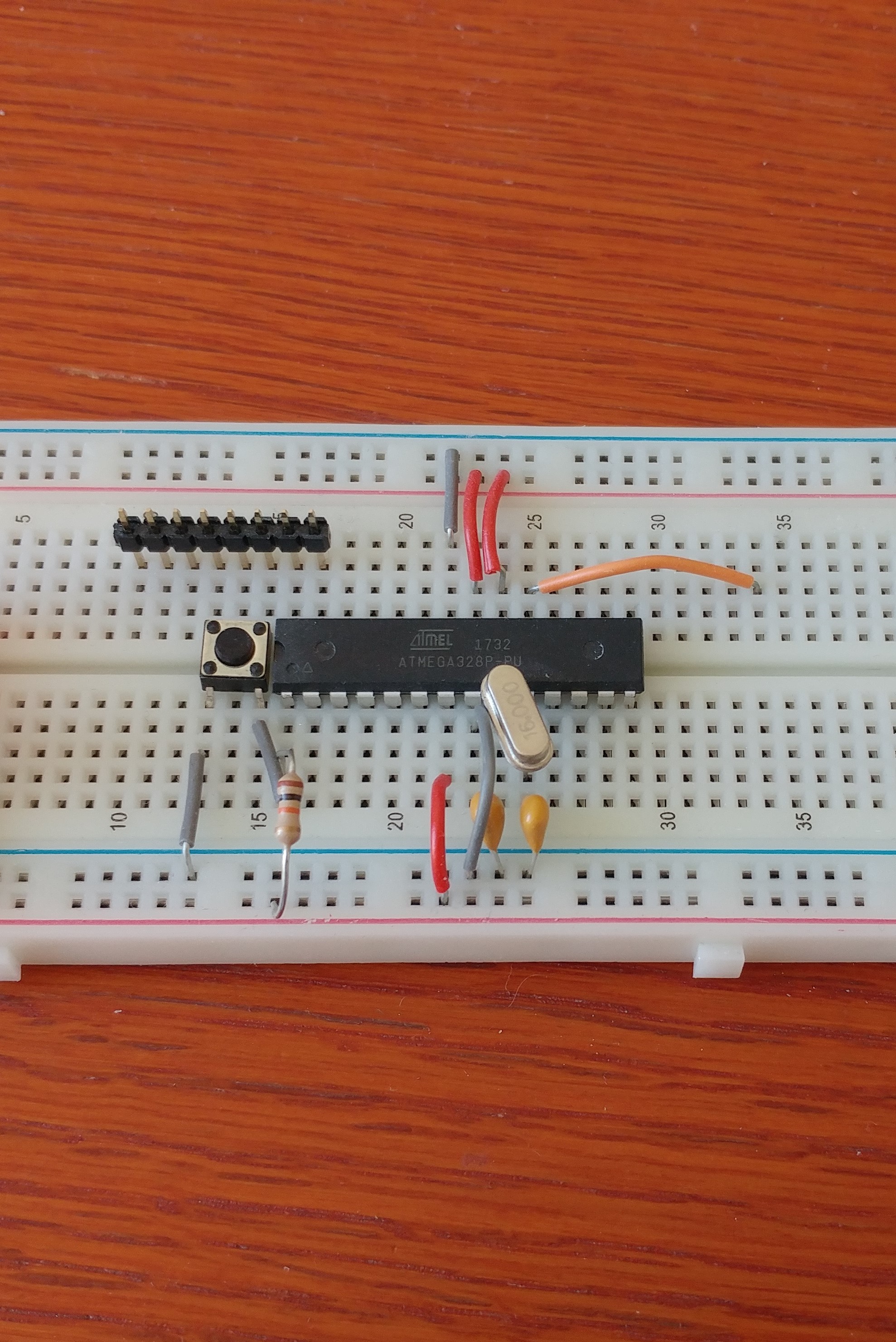
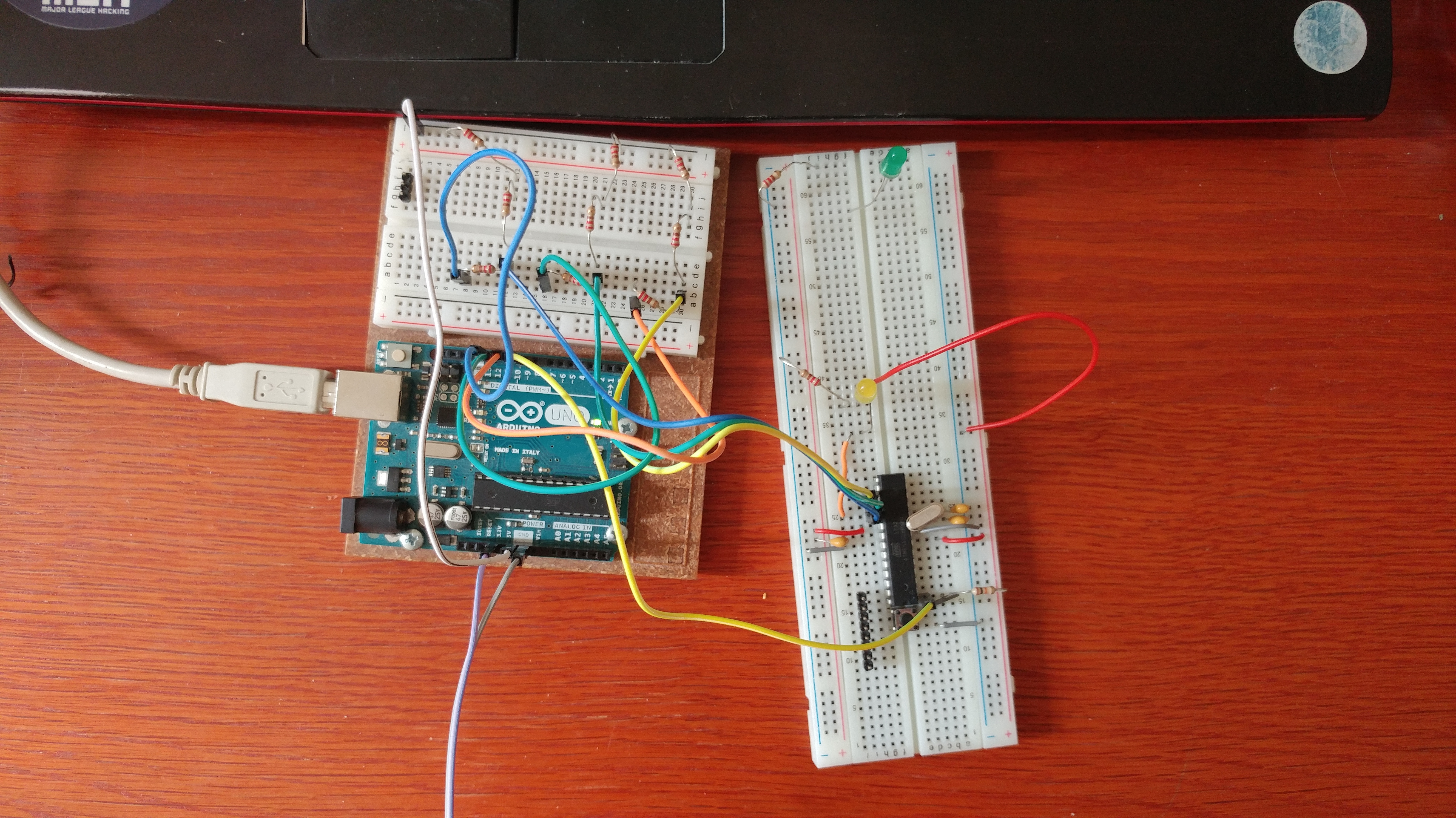
Objectives:
- To build a standalone Arduino that runs on 3.3V off an 8 MHz external clock.
- To program it via ISP (also known as ICSP, in-circuit serial programming) from an Arduino Uno (running at 5V)
- To edit the bootloader file and burn the bootloader (via ISP)
- To be able to read serial information from the standalone Arduino via FTDI cable
- To be able to read serial information from the standlaone Arduino without the FTDI cable
Preamble:
I was trying to build my standalone project but didn't see any comprehensive guides on running, programming, and monitoring a Standalone Arduino - particularly one running off an 8Mhz external clock and 3.3V and programmed by an Arduino UNO. I've pieced together a number of separate guides and I've tried to reference where I got the information from to give credit where credit is due. This guide is the result of many days looking for solutions and finding parts of it at a time while I was building my own project.
Also, I've linked several useful products that would come in hand not because I'm affiliated with any of the companies, but because it is relevant to include the specific items I am referring to.
Common questions before we start:
- Why do you need to program it with ISP and monitor via FTDI? Why can't you just program it via FTDI?
We'll have to change the fuse settings by burning a new bootloader in and you can't do that via serial communication. You must burn the bootloader via ISP. This is also useful for those who don't have a pre-bootloaded ATMEGA328 chip.
- Why don't I just use an ISP cable with serial monitoring, like this one?
Perhaps, like me, you just happen to not have one and rather than waiting for one to be shipped you' like to use what you have! I happen to have an FTDI cable (although you'll find ultimately you don't even need it: it just makes your life easier).
- Don't I need a logic level shifter from the Uno to the standalone Arduino?
Yes, you do, but I'll show you how to make one yourself. Like the ISP cable, I happen to not have one.
- I want to run it off of external power. How do I do that?
There are plenty of guides that show how to run a standalone Arduino off of battery power. I will write how I did it and link it here [will insert later].
THE GUIDE
Building the Standalone Arduino

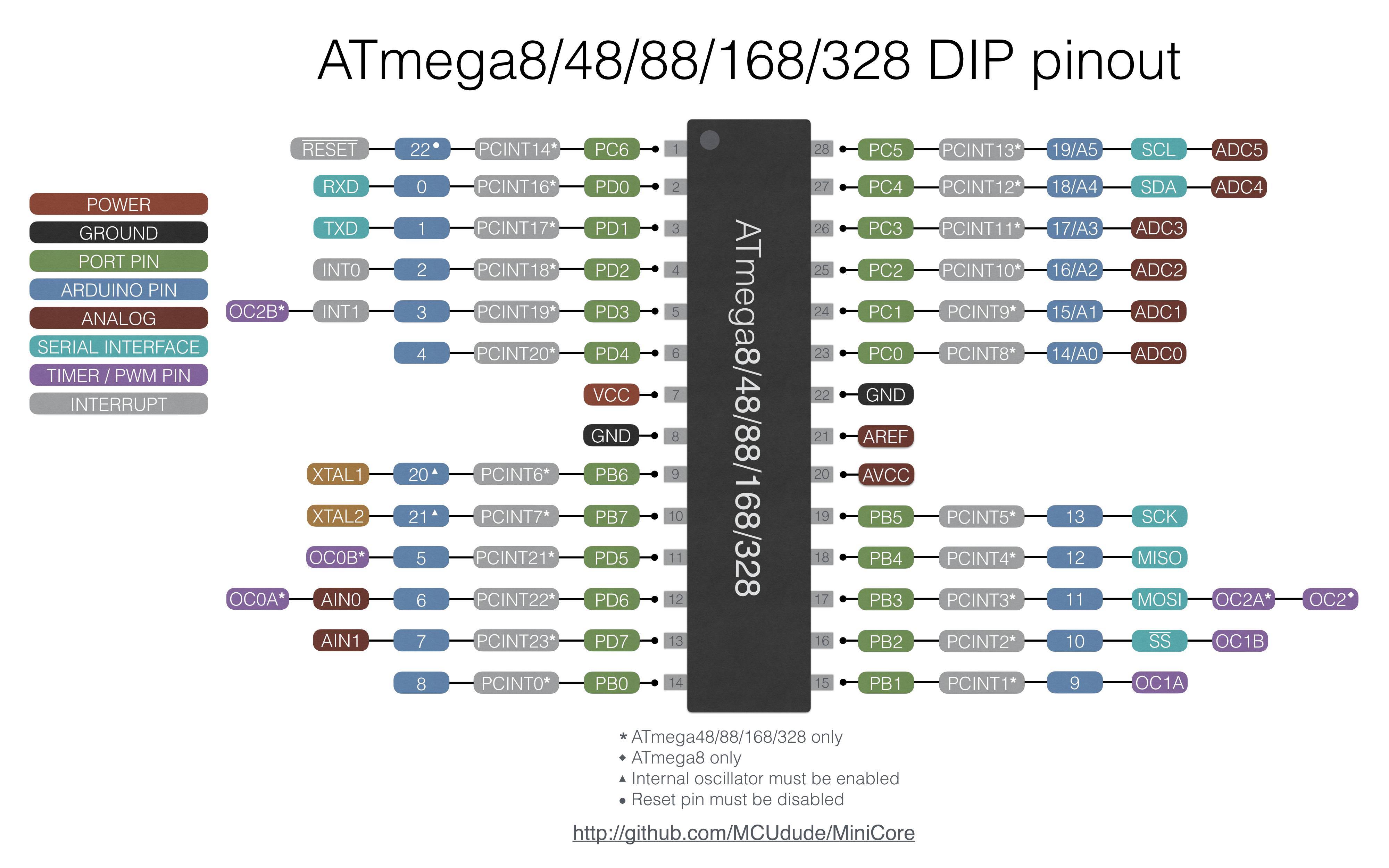
1) Build the standalone Arduino from this link. The only part of the guide you need is the "ATMEGA8/168/328 Basics".
- you can power the standalone Arduino from the 3.3V out of the Arduino Uno. (You can skip the first section of the tutorial titled "Adding circuity for a power supply."
- Substitute the 16 MHz clock with an 8 Mhz clock.
- Add 0.1 uF caps between: VCC and Gnd (both sides) VRef and Gnd.
- I don't have these included in the picture but I do have them in my projects!
- I know it's a 16 MHz oscillator in the photo. I took the photo before I figured out everything I did in the guide!
ATMEGA328p pinout image source here.
Common Troubleshooting Tips
- Ensure you have reset set high via a 10k resistor from VCC to pin 1
of the ATMEGA. If the pin is grounded or floating it will not work. - Double check that you've inserted wires and the oscillator correctly.
- Ensure you use 22pF capacitors for the 8 MHz oscillator. It will not work otherwise.
- Ensure the device is powered.
The ISP Wiring
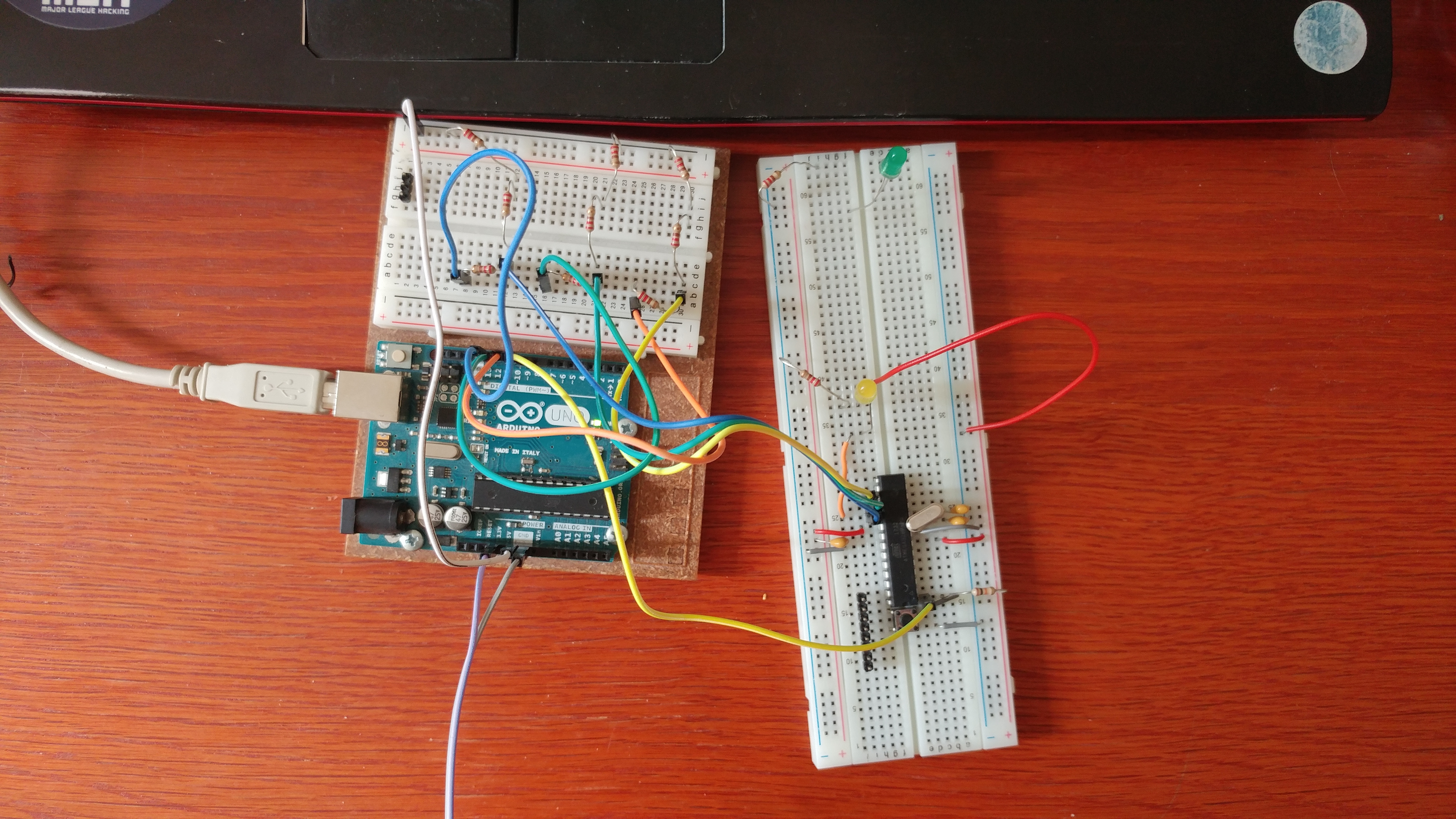
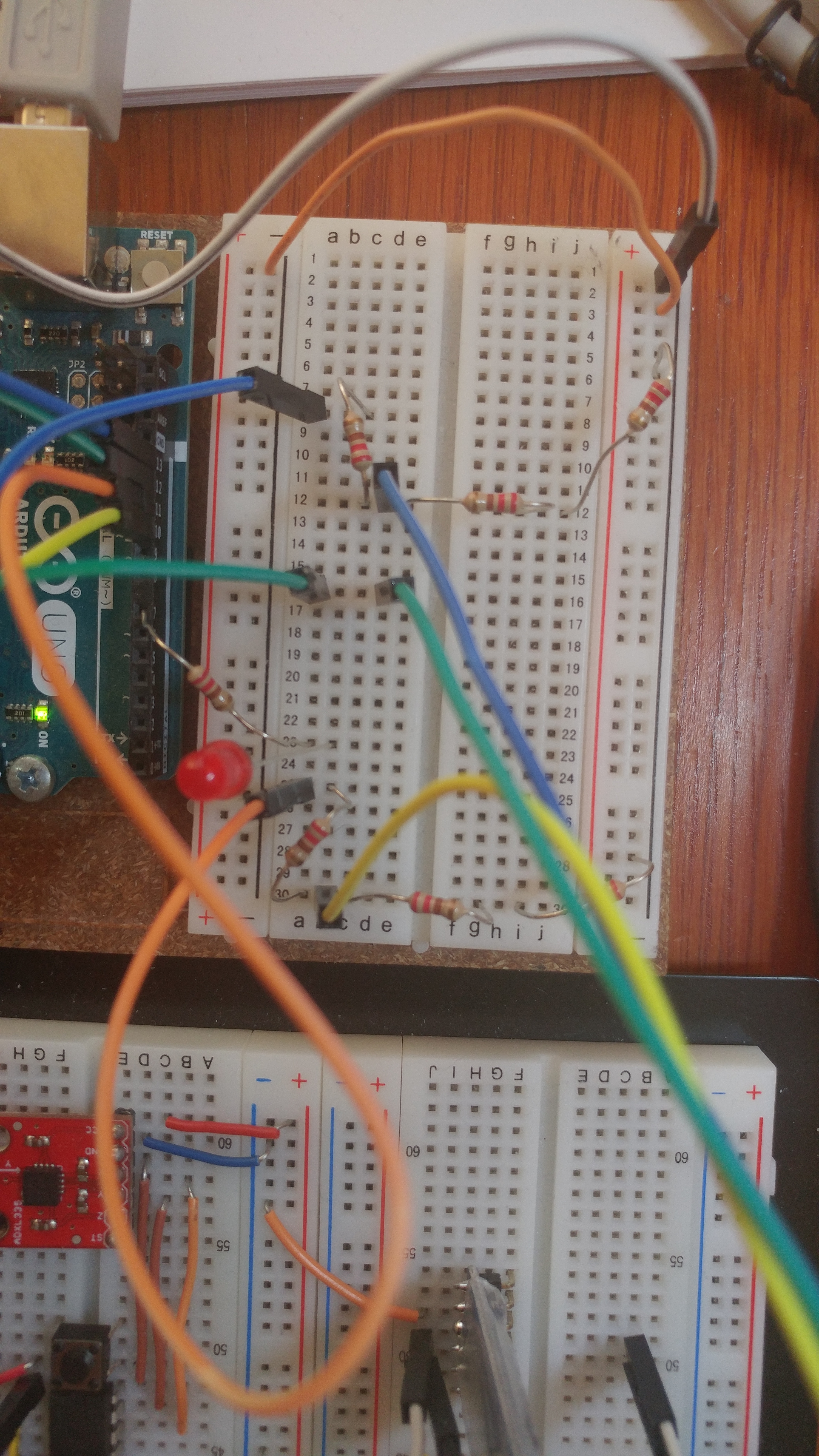
2) Create the ISP portion.
You'll be following this guide here with a small but very important step.
The reason you can't just follow the guide is because you're missing a crucial portion: you cannot program a 3.3V device directly from the 5V connections. (At least, I couldn't: it wouldn't work until I did this). You need to insert a logic level shifter that shifts the 5V signals from the UNO to the 3.3Vstandalone Arduino.
If you don't have a logic level shifter board, you can make one using resistors. All a logic level shifter really is (so long as you're shifting down) is a voltage divider. You'll need 6 of the same resistors, nothing too high or too low. I used 220 ohm resistors, but I'm sure even 10k resistors would work.
For SCK (digital pin 13) and MOSI (digital pin 11), use a voltage divider to cut the voltage by one third. In essence you're going to have one Uno SCK and MOSI, then a resistor (220 ohm), then SCK and MOSI connected to the standalone Arduino and 2 resistors (440 ohm total) to ground.
So, read the guide linked at the beginning of this section, but include voltage dividers in between SCK and MOSI.
Remember, SCK, MISO, MOSI, and RESET are pins 13, 12, 11, and 10 on the Uno but are pins 19, 18, 17, and 1 on the standalone Arduino!
Common Troubleshooting Tips
- CHECK THE WIRING
- If you're getting a device signature of
all 0's when trying to write program, then your wiring is almost certainly off,or the standalone Arduino is not getting power. - Also, ensure that you've got the reset wire from 10 on the Uno to 1 on the standalone Arduino
- If you're getting a device signature of
- CHECK THE VOLTAGE DIVIDERS
- Ensure you've got voltage dividers with a ratio of 1:2 (high side: low side) for the resistors for both SCK and MOSI. E.g. a 220 resistor on the +5v side and then 2 220 ohm resistors (440 ohm total) towards ground with the signal towards the standalone Arduino in the middle.
Edit the Bootloader File, Burn the Bootloader, and Upload Your Sketch
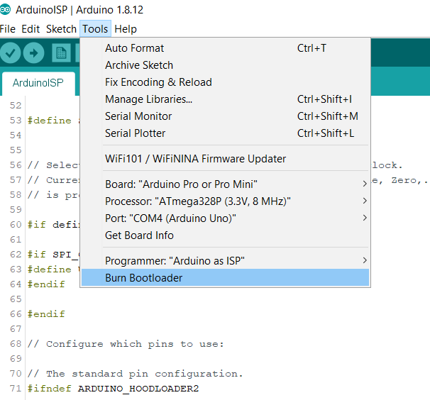
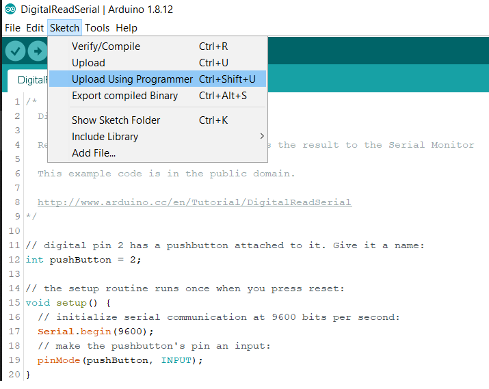
3)Edit the bootloader (boards.txt) file and burn the bootloader to the standalone Arduino. Upload your sketch.
Editing the bootloader file
In order to get the standalone Arduino running, you'll have to edit the brownout fuse settings of the bootloader. Otherwise, you'll be able to burn a bootloader on it but won't be able to run any sketches.
You can remove the brownout detection completely, but I wouldn't recommend it. Instead, we're going to lower it from 2.7V (what came on my chip as default) and replace it with 1.8V. Ultimately, however, you can choose what brownout settings you want by using the fuse calculator here.
My boards file was in the following location:
C:\Program Files (x86)\Arduino\hardware\arduino\avr
However, you may have more than one boards.txt file in your hardware folder other than /arudino/. You're going to be editing the boards.txt file in the /arduino/ location because you're going to be modifying the ATMEGA328p (3.3V, 8 MHz) section.
You may lose the edited boards.txt file if you reinstall or update the Arduino IDE (according to this post). This means that if you update Arduino IDE, you'll have to change these settings again if you want to create another of the same standalone Arduino.
In the boards.txt file, scroll down or search for "Pro Mini". The section is titled "pro.name=Arduino Pro or Pro Mini". Scroll down to the subsection "pro.menu.cpu.8MHzatmega328=ATmega328P (3.3V, 8 MHz)".
Look for the line that says "pro.menu.cpu.8MHzatmega328.bootloader.extended_fuses=___"
Change the settings to xFE. (pro.menu.cpu.8MHzatmega328.bootloader.extended_fuses=0xFE).
Save and exit.
Burning the Bootloader
Once you've done this, you can follow the "Instructions" section on the ISP guide from steps 1 to 5.
Some things to clarify:
- When you are uploading the "Arduino as ISP" sketch, you need ensure you have the correct COM port and processor selected.
- In this case, it means that you've selected the COM port of your Arduino in Tools->Port: COM X (Arduino Uno) and the board is Arduio Uno.
- Select the correct programmer: under Tools->Programmer->Arduino as ISP.
- NOT ArduinoISP or ArduinoISP.org
- Before burning the bootloder, change the board "Pro or Pro Mini" and Processor to "ATMEGA328p (3.3V, 8 MHz)".
- You won't see the processor section until you select the correct board type.
Burn the bootloader onto the standalone Arduino BEFORE you attempt to write sketches on it.
Uploading the sketch
This is very important. You are now able to program either Arduino: the Uno and the Standalone. If you do not upload to the correct device, you have to repeat the section above and rewrite Arduino as ISP program on the Uno.
When you upload your sketch, ensure you click Tools -> Upload using programmer OR click Ctrl+Shift+U. You can also hold shift and click the arrow icon, but do not click the arrow icon without holding shift.
Common Troubleshooting Tips
- Turn on verbose output for troubleshooting.
- "The device signatuere is all 0's!" [This one is very likely to occur.]
- see ISP Wiring section. Either you've wired the standalone Arduino incorrectly or it is not being powered on.
- Ensure you've selected the correct COM port and board / processor. When you are burning the bootloader, you MUST ensure you are burning the Pro Mini 3.3V 8 MHz bootloader on it or the fuses won't set correctly.
- "I've edited the boards.txt file but don't see the edits"
- Ensure you've edited the correct boards.txt file. Try updating Arduino IDE if the edits aren't working, or remove other folders in your /hardware/ folder temporarily.
- "I can't find the pro mini section of boards.txt!"
- You're not looking in the right boards.txt file. Check the Arduino//hardware/arduino/ folder.
Serial Communication
You can really do this via 2 methods, so if you don't even have an FTDI cable / breakout board it's not the end of the world. And remember, the sketch you uploaded to the standalone Arduino must have Serial.print statements for you to read: if you didn't write it in the program, you won't see anything!
If you don't have an FTDI cable
After you've burnt the bootloader and written the program you want, you can (very carefully and remembering which orientation it goes back in) remove the ATMEGA328 DIP chip from the Arduino Uno. I recommend using a flathead for this.
You can connect the standalone Arduino's RX to Uno's RX and TX to TX. Yes, it's normally the opposite, but you can think of the Uno as "forwarding" the info to the IDE's serial monitor. That's why you don't connect RX to TX and TX ro RX in this case. When you're running your program, ensure you have the Arduino Uno's COM port chosen and open up serial montor. You'll be able to see the standaone Arduino's serial output.
(This solution is credited to Robin2 here.)
If you do have an FTDI cable / board
(I'm using Sparkfun's FTDI board which I've converted to 3.3V using the solder pad on the back)
Simply connect the breakout board's GND to the standalone Arduino's ground and connect the breakoutboard's RX to the Arduino's TX and TX to RX. (If you are JUST serial monitoring and are not writing anything back, you can just connect the breadoutboard's RX to Arduino TX).
Keep in mind at this point you have the option of powering the standalone Arduino via the Uno OR the FTDI Cable. Do not connect both power sources at the same time! Note that you'll have to change the COM port since it's going to be different than the Arduino Uno COM port.
Common Troubleshooting Tips
- "I'm not seeing anything!"
- Check if you have the correct COM port enabled.
- Check if you have the most recent FTDI drivers.
- ENSURE GROUND IS CONNECTED.
- "All I see is garbage output in the serial monitor!"
- You're getting something which is a good sign.
- However, check the voltage of the FTDI board.
- The standalone Arduino is outputting 3.3V on it's TX and the FTDI board may not pick it up if it's expecting 5v.
- Check the baud rate.
- Ensure you have ground connected and only one power source connected! (I.e. don't power the standalone Arduino from the Uno AND your FTDI board.