Spider Robot DIY (Quadruped)
by xprobyhimself in Circuits > Robots
2986 Views, 22 Favorites, 0 Comments
Spider Robot DIY (Quadruped)
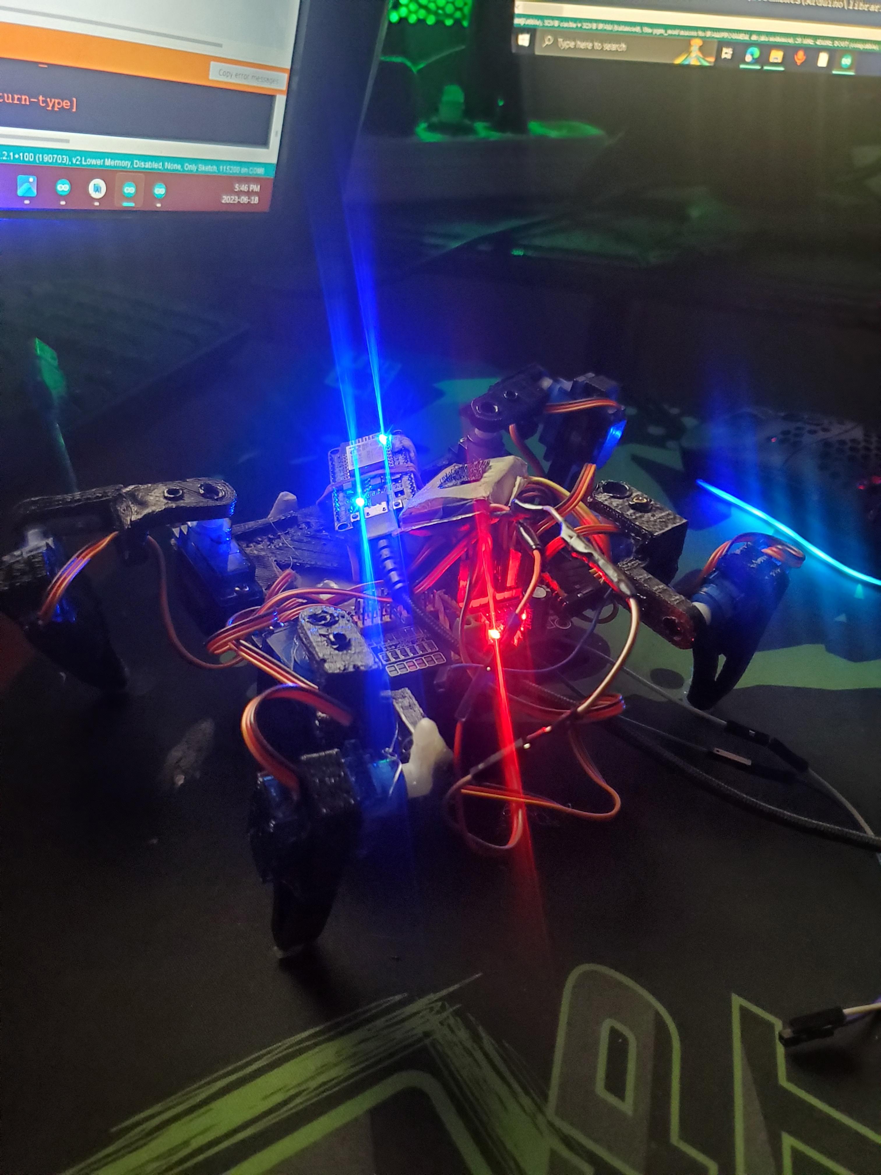
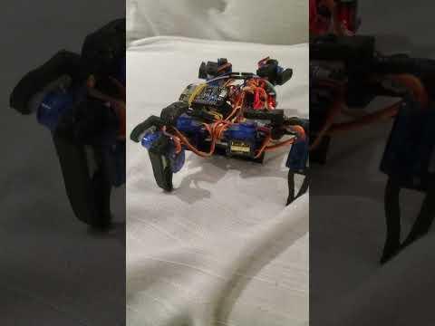
This is a simple quadruped spider robot, fully 3D printed and powered by an ESP8266 microcontroller (You can use any microcontroller, such as Arduino or Raspberry Pi...). It uses 8 servo motors for movement and is designed for easy assembly. The robot's compact design makes it a great project for beginners.The ESP8266 enables wireless control, offering endless possibilities for upgrades. For advanced users, this opens the door to taking the robot to the next level with enhanced features and capabilities.
The next version will feature wireless control through a phone app, advanced inverse kinematics, a Ultrasonic distance sensor, and a gyroscope for improved balance. Stay tuned for these exciting upgrades!
Supplies
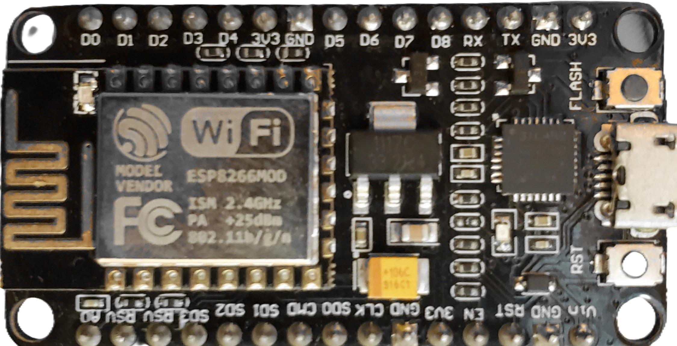
ESP8266 (You can use any board, such as Arduino, Raspberry Pi, etc.)
- Servo Motors (I used 8 Micro Servo SG90)
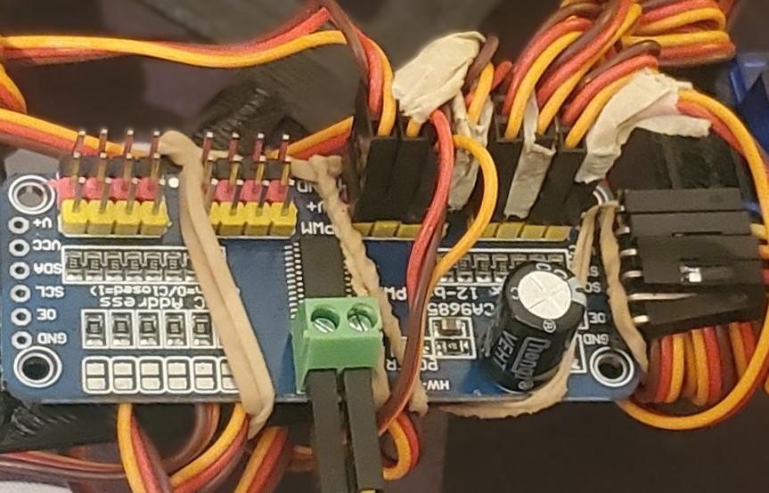
- Servo Driver PCA9685
- Jumper Wires (7 pieces)
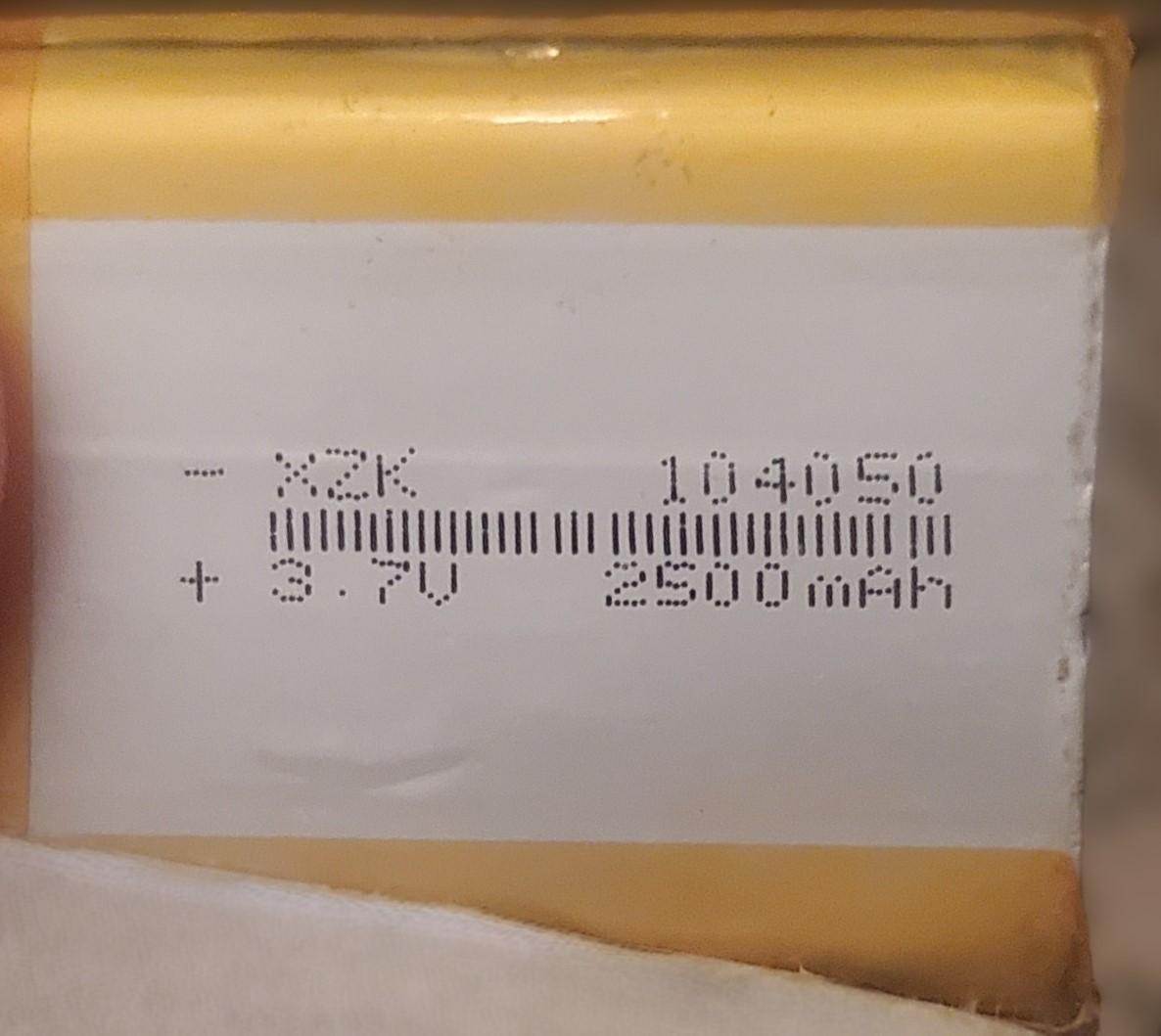
- Battery (I used a 104050 2500mAh 3.7V battery)
- 3D Printer
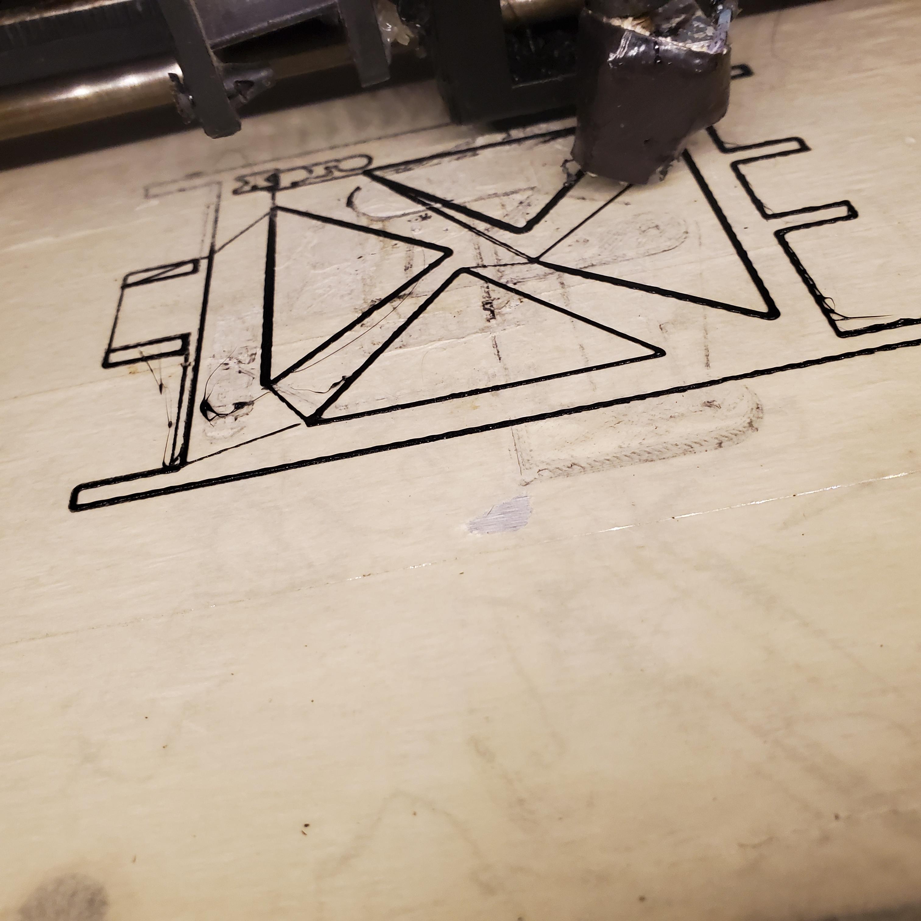
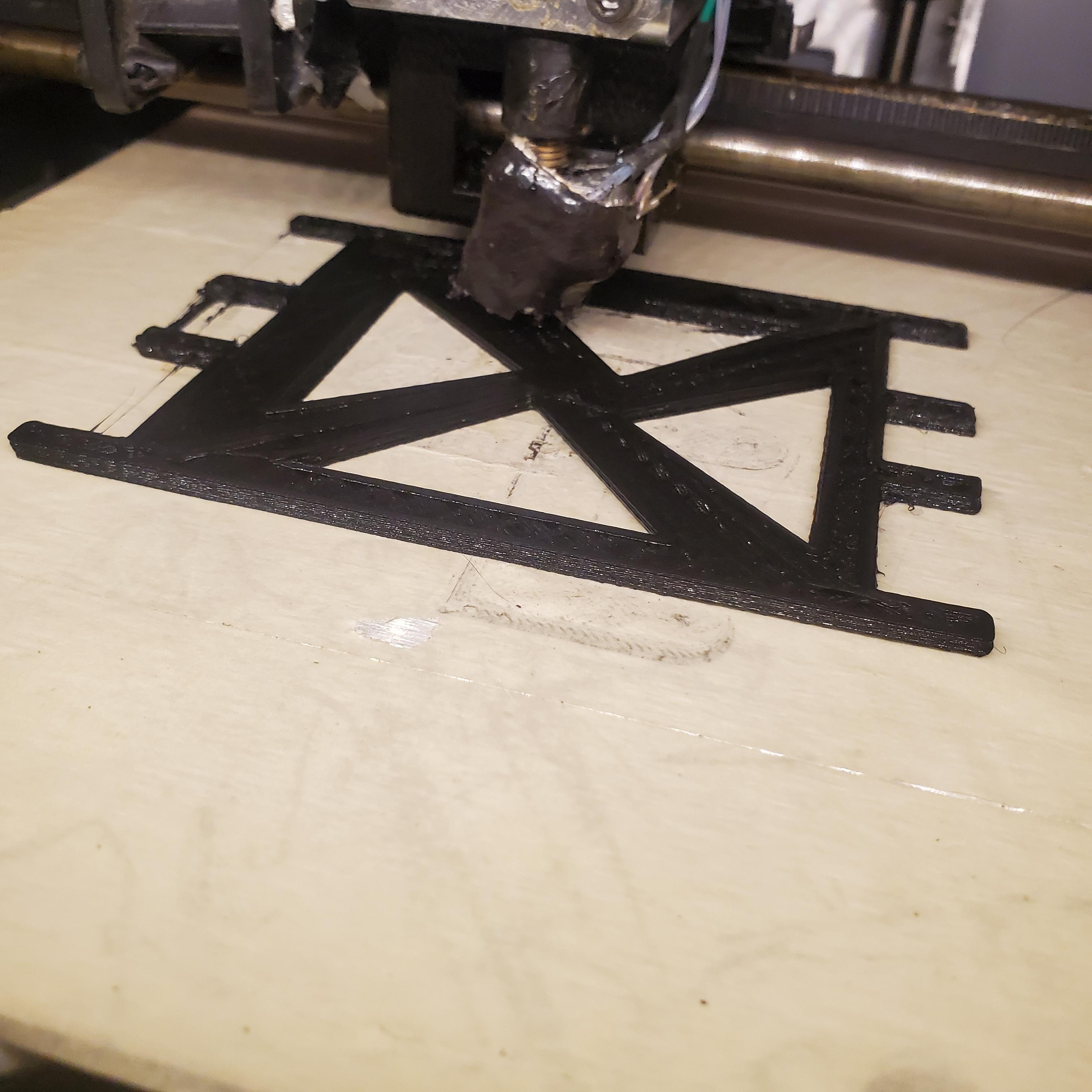
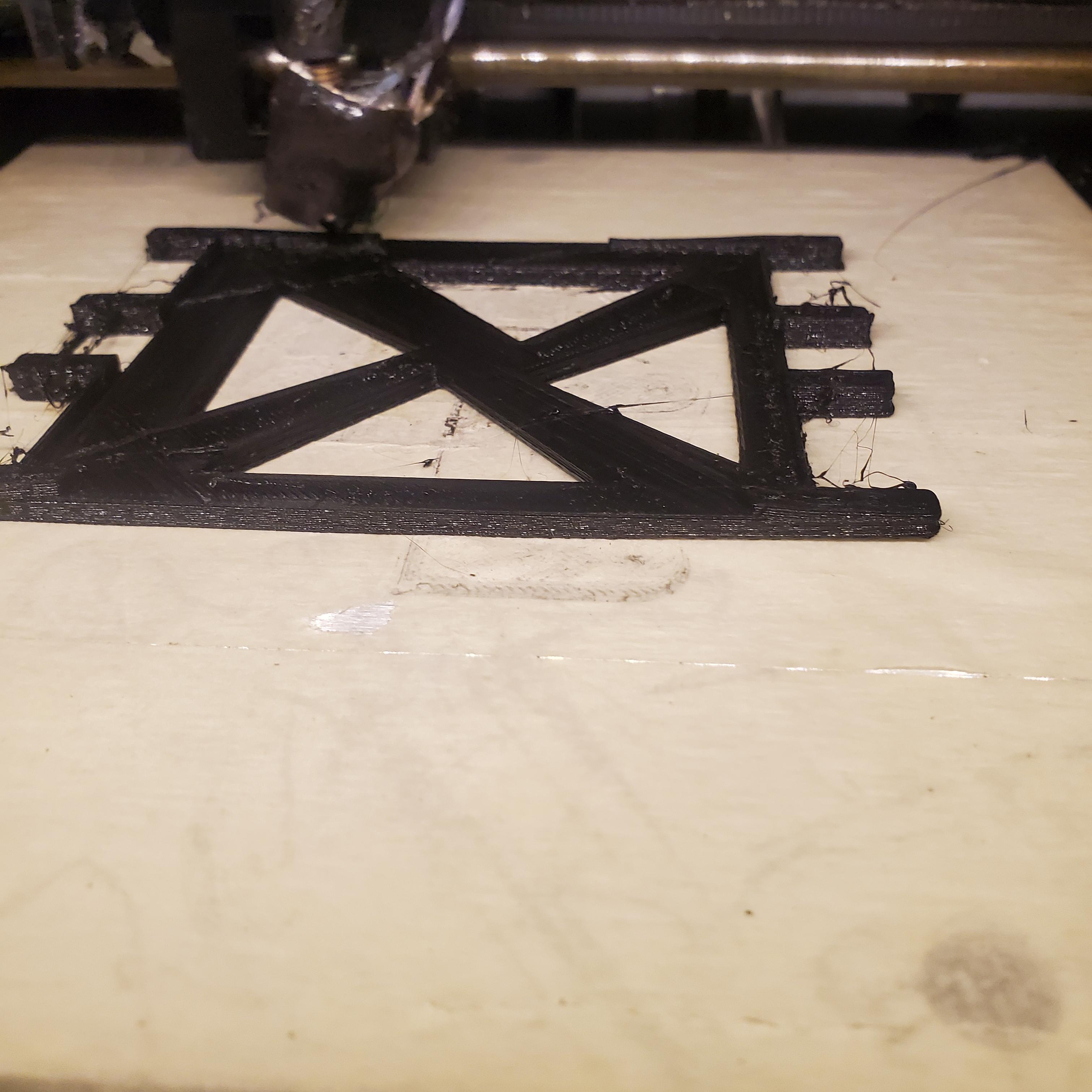
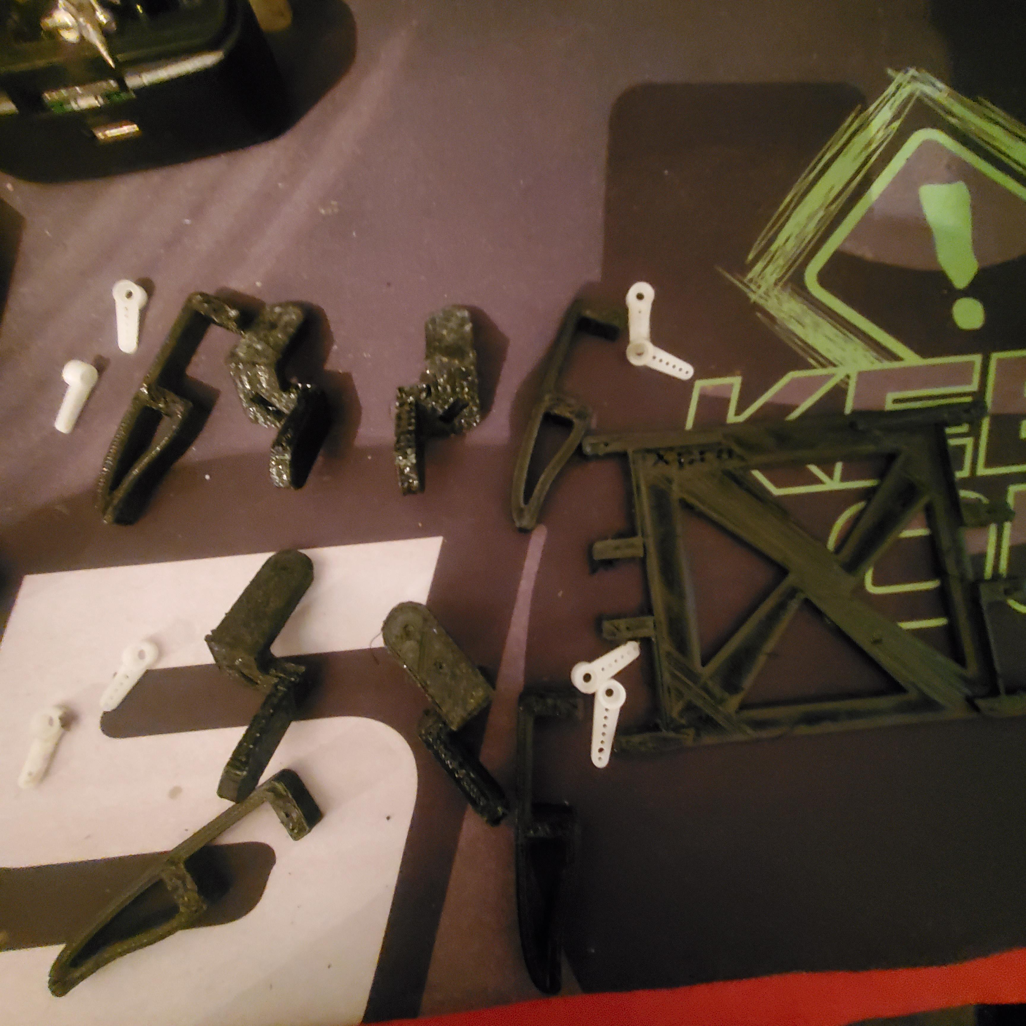
3D Printing
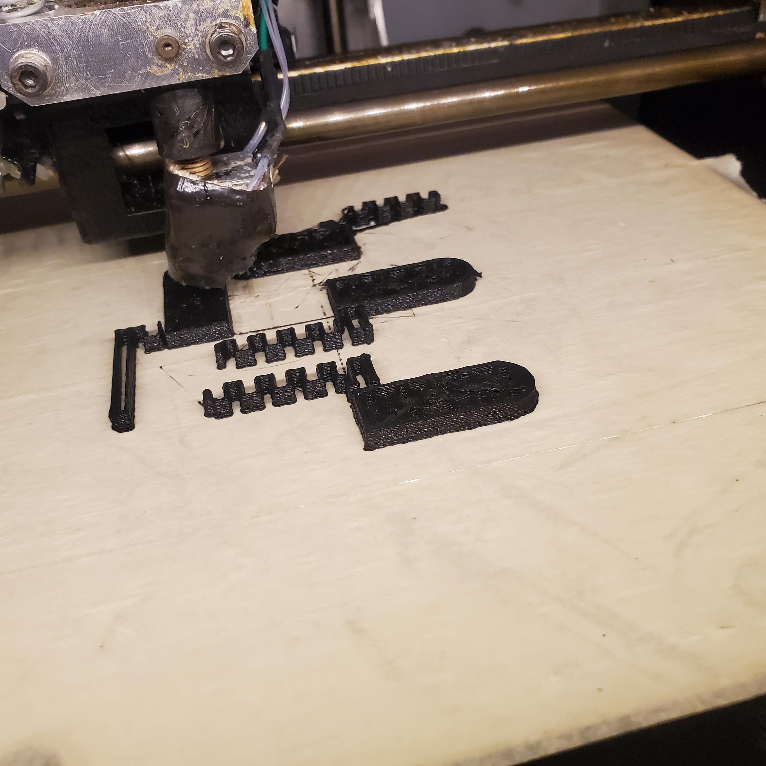
Slice the Models
- Import into Slicer Software: Load each 3D model into slicing software like Cura, PrusaSlicer, or similar.
- Adjust Settings: Set the correct print settings, such as layer height, infill density, print speed, and support structures.
- Layer Height: Choose a lower layer height (e.g., 0.1-0.2mm) for smoother surfaces.
- Infill Density: A 20-30% infill is often sufficient, but for more strength, you might go higher.
- Supports: Enable supports for overhanging parts, especially for complex geometries like the legs.
- Orientation: Position each part for optimal printing, ensuring minimal use of supports and better adhesion.
Start the Print
- Preheat and Load Filament: Ensure your 3D printer is preheated to the correct temperature for the filament you're using (e.g., PLA, ABS) I'm using PLA.
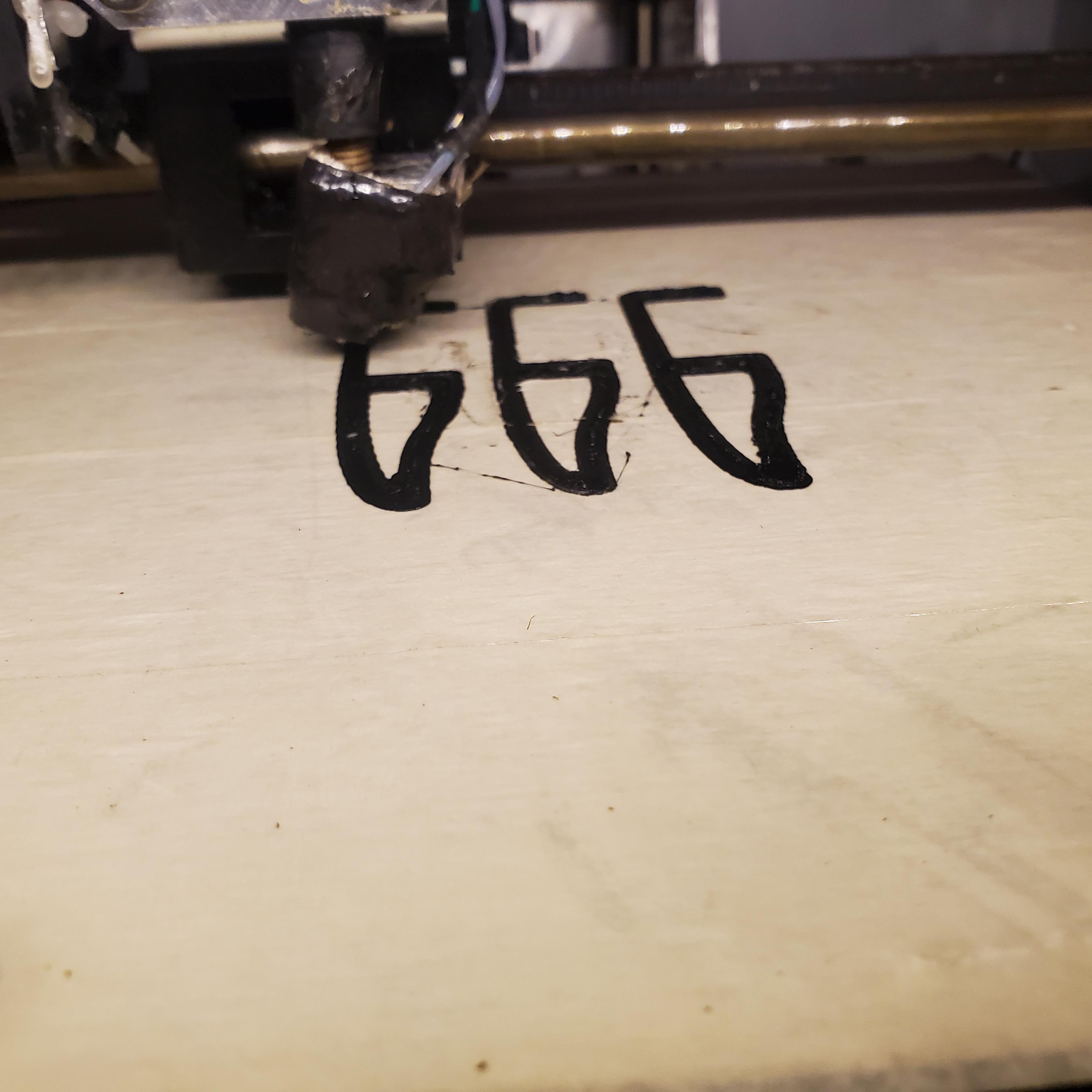
- Print the Body: Begin by printing the body since it's typically the largest part. Ensure the printer is functioning correctly before leaving it unattended.
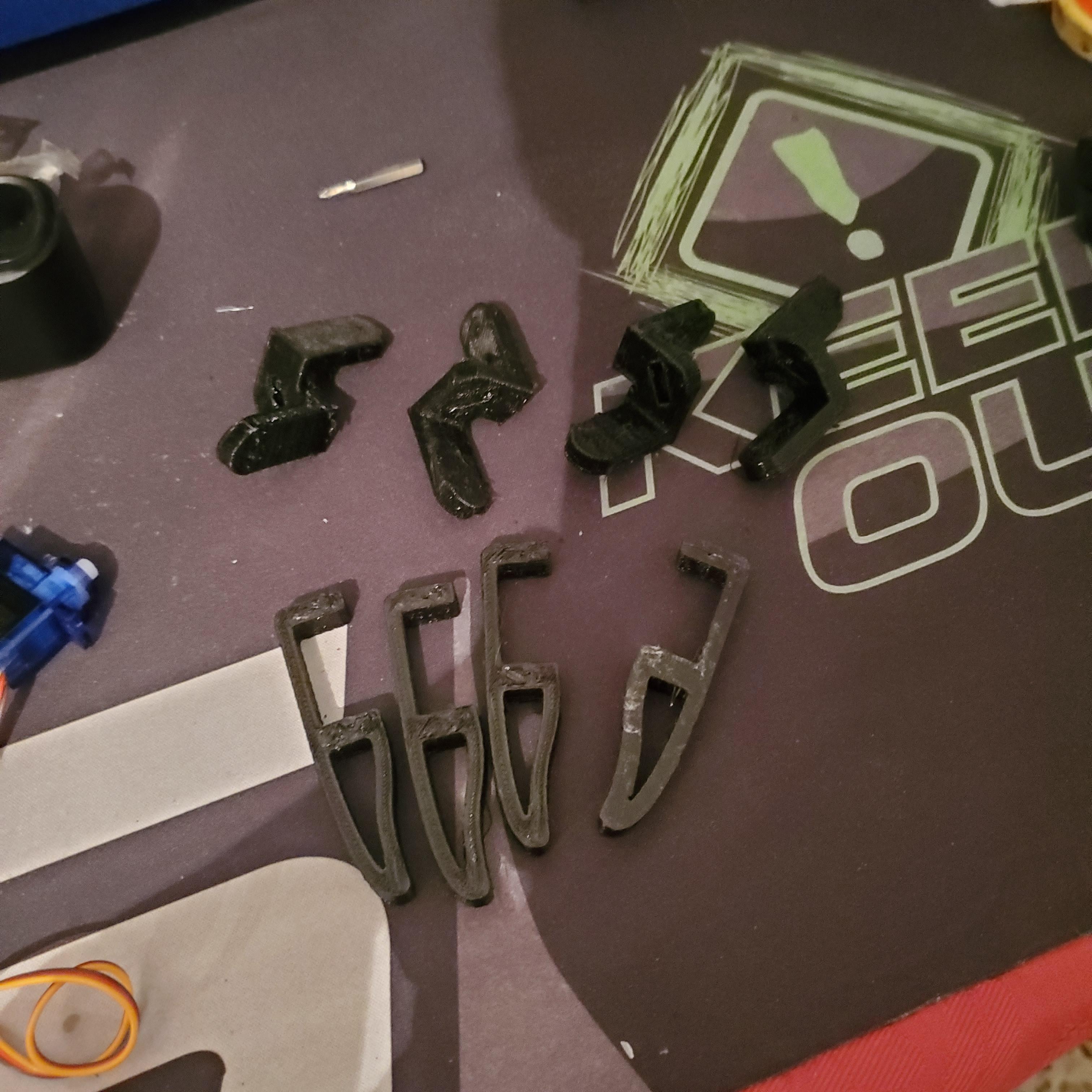
- Print Upper Leg 1 and Upper Leg 2: Once the body is done, proceed to print the upper leg components.
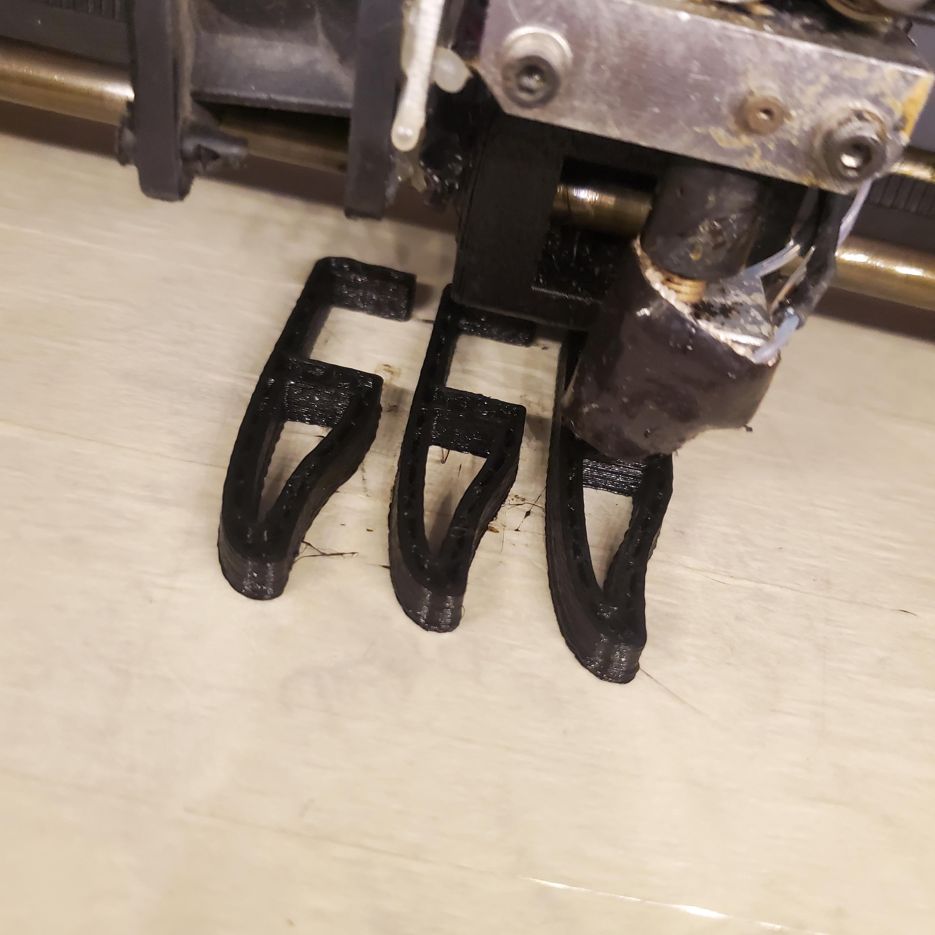
- Print Leg 1 and Leg 2: Finally, print the lower leg parts.
Post-Processing
- Remove Supports: Carefully remove any supports after printing using pliers or cutters.
- Sand the Parts: If needed, lightly sand the parts to smooth out rough edges or imperfections.
- Fit Check: Test the fit of the parts together to ensure they align and function as intended.
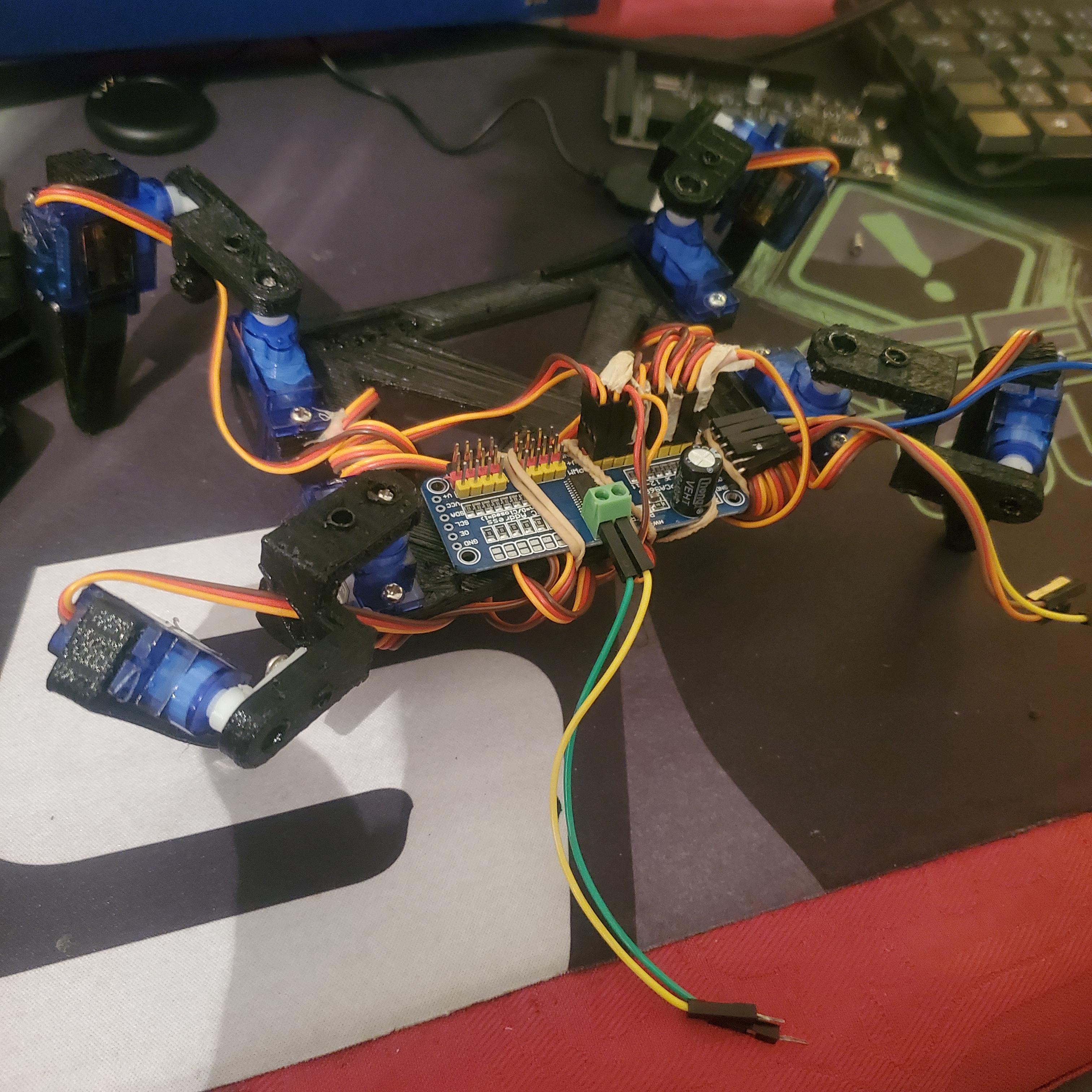
Assembling
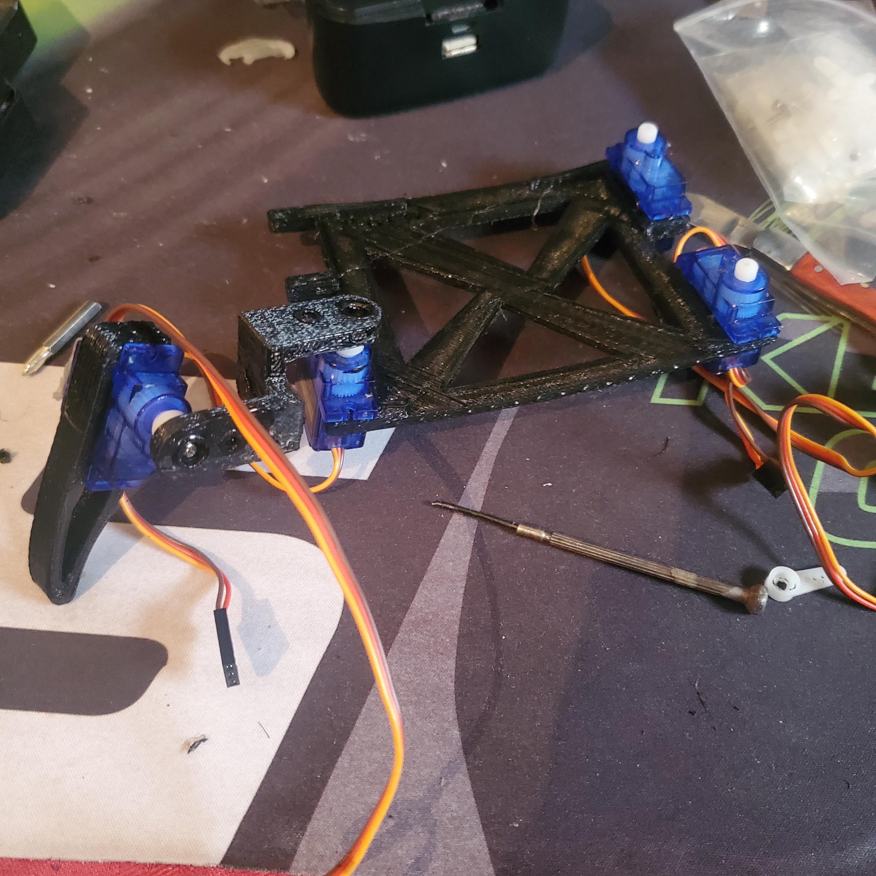
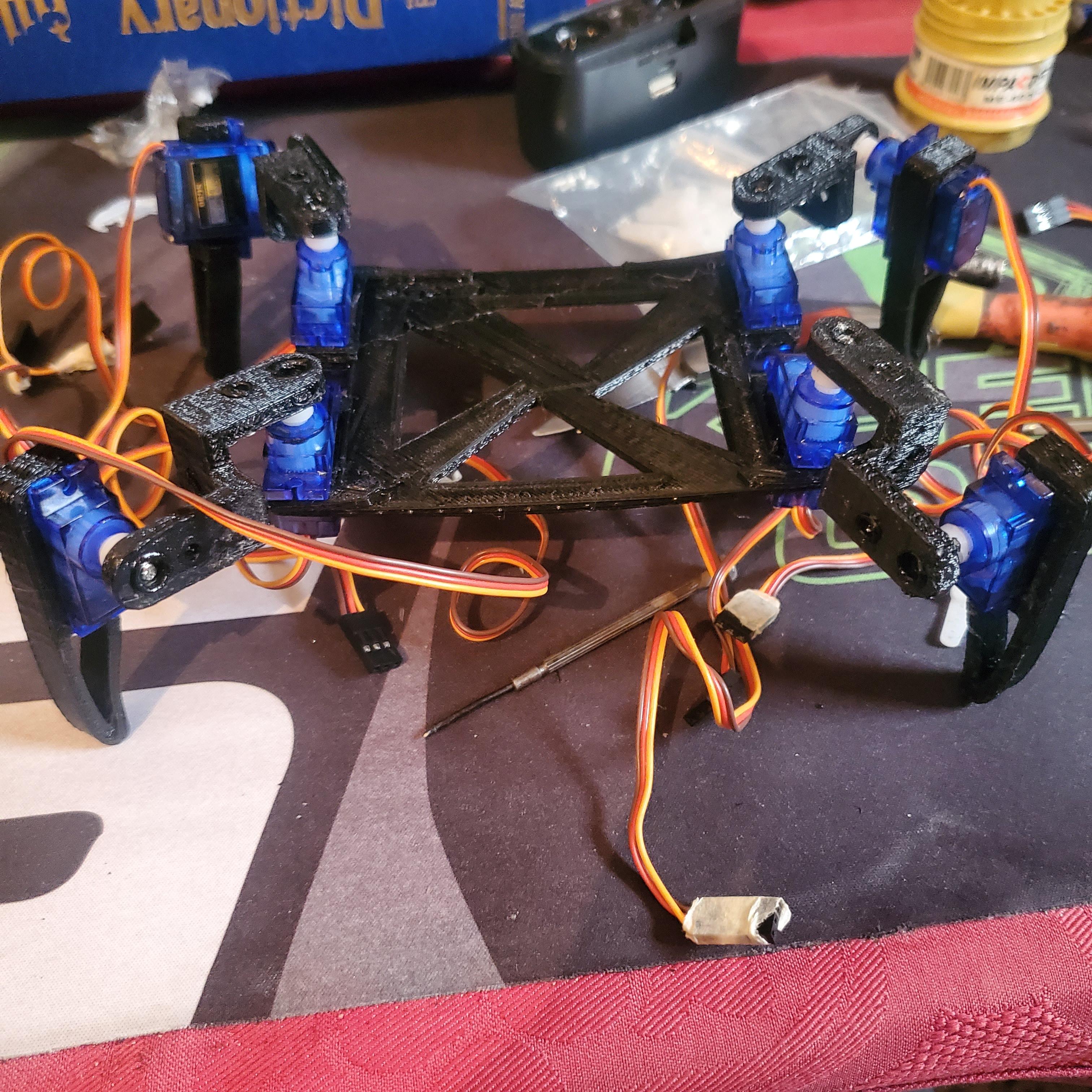
you can use the 3D module provided as guide to assemble those parts easily
1. Gather Your Components:
- 3D-Printed Frame and Legs: Ensure all 3D-printed parts are ready, including the main body, leg joints, and feet.
- Servo Motors: You need eight servo motors, two for each leg.
- Screws and Nuts: To secure the servos to the 3D-printed parts.
- Wires and Connectors: To connect the servos to the control board.
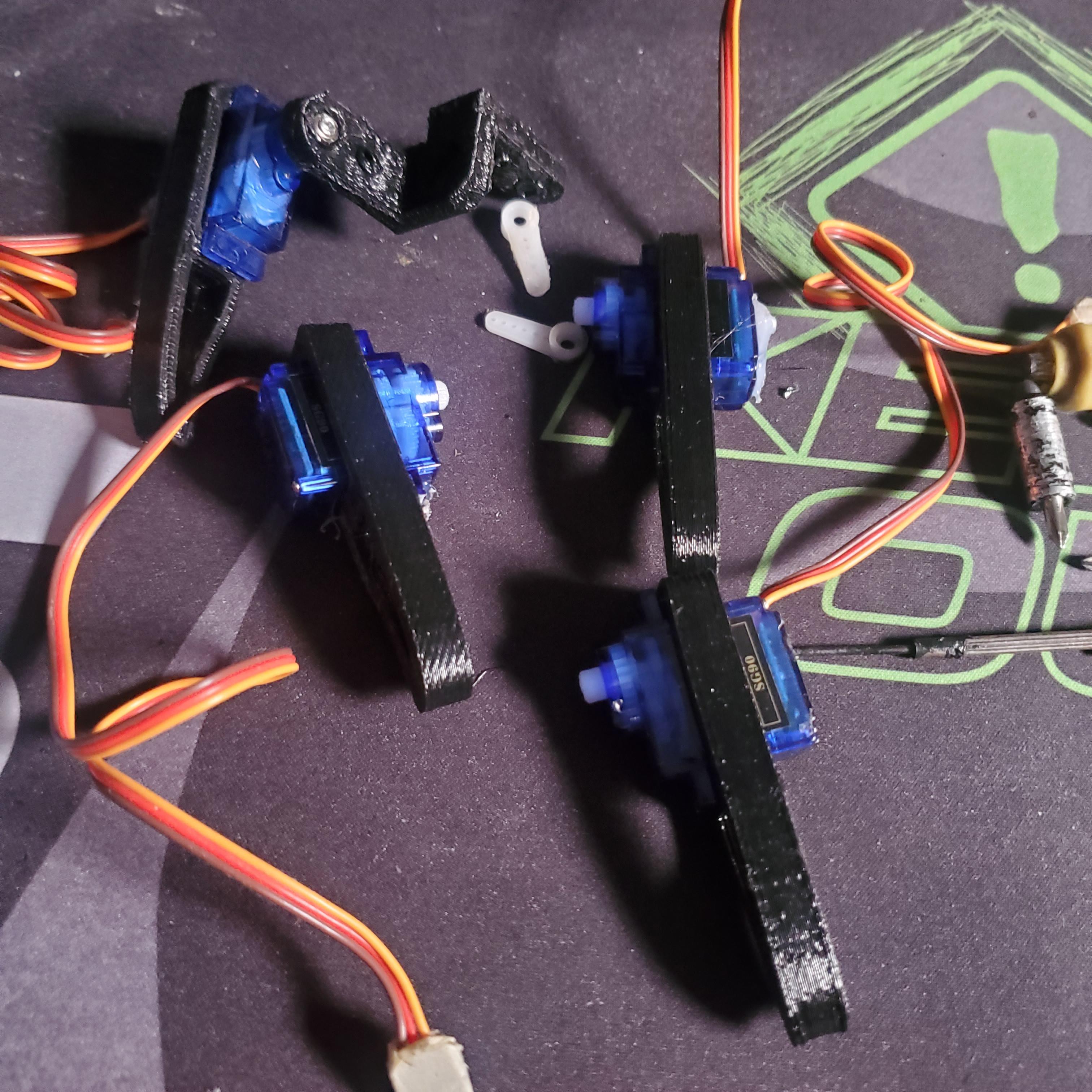
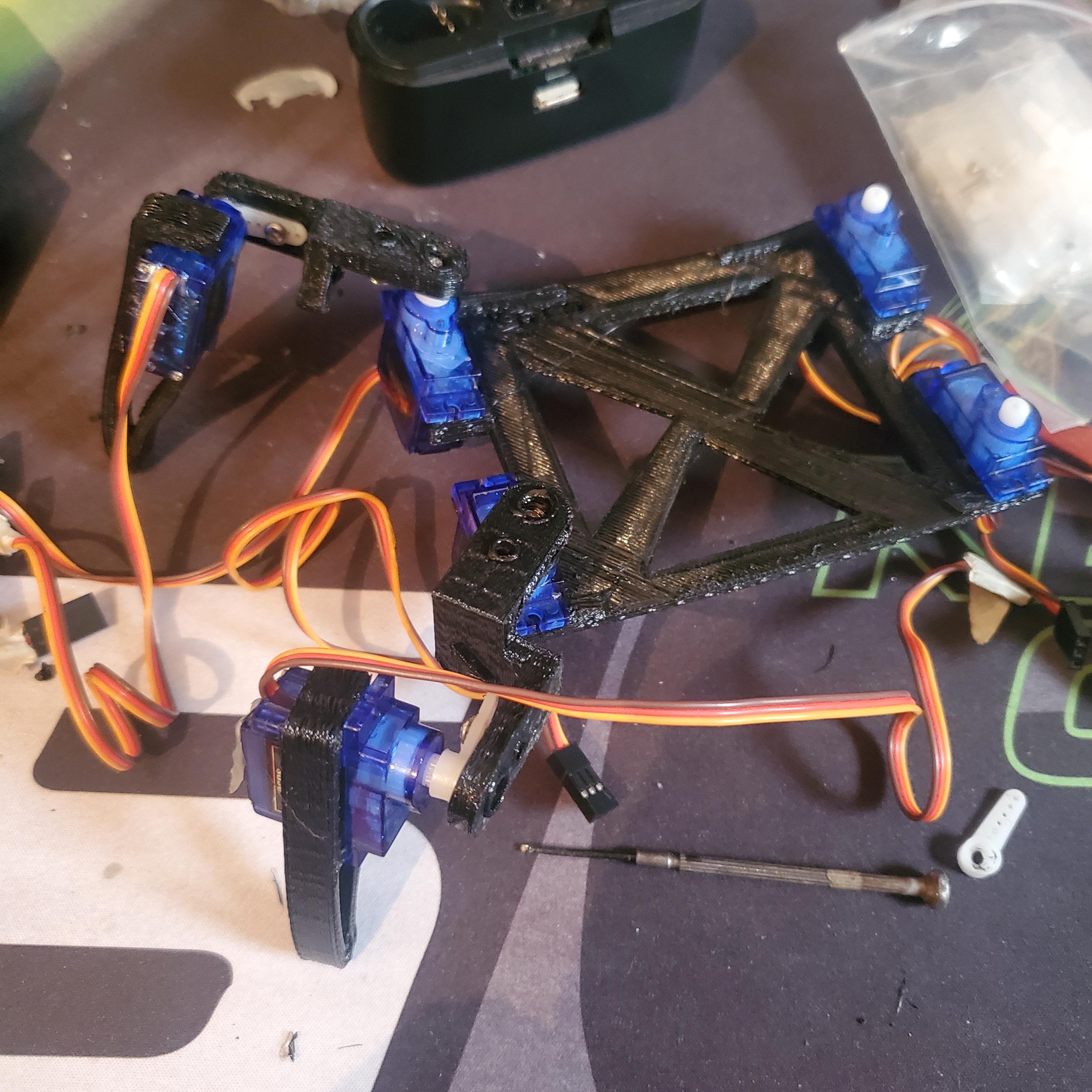
2. Attach Servos to the Legs:
- Leg Joints: Attach one servo to each leg's upper joint and another to the lower joint. The upper servo will control the leg's up-and-down movement, while the lower servo will control forward and backward movement.
- Feet Assembly: Secure the lower part of each leg, which is the foot, to the second servo motor.
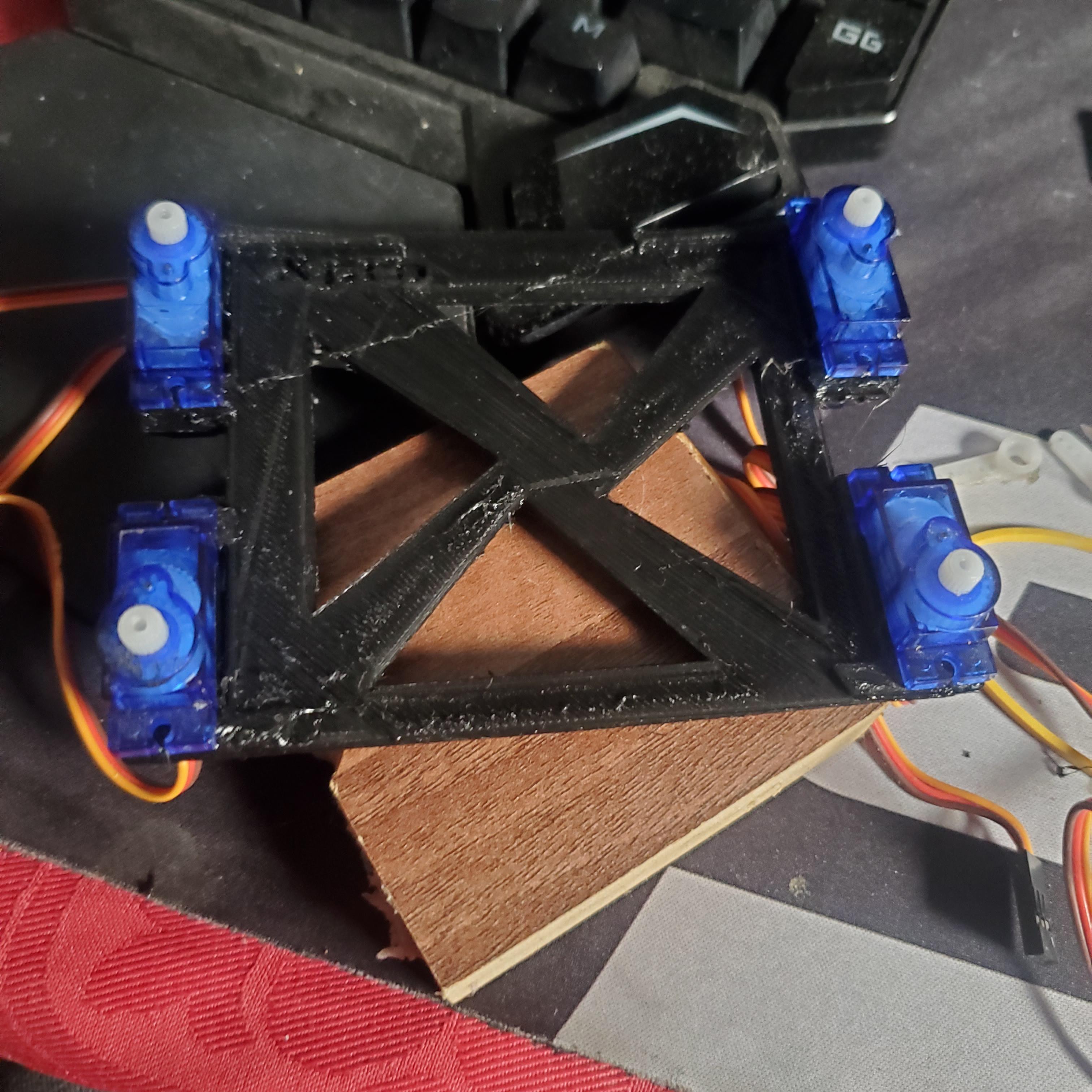
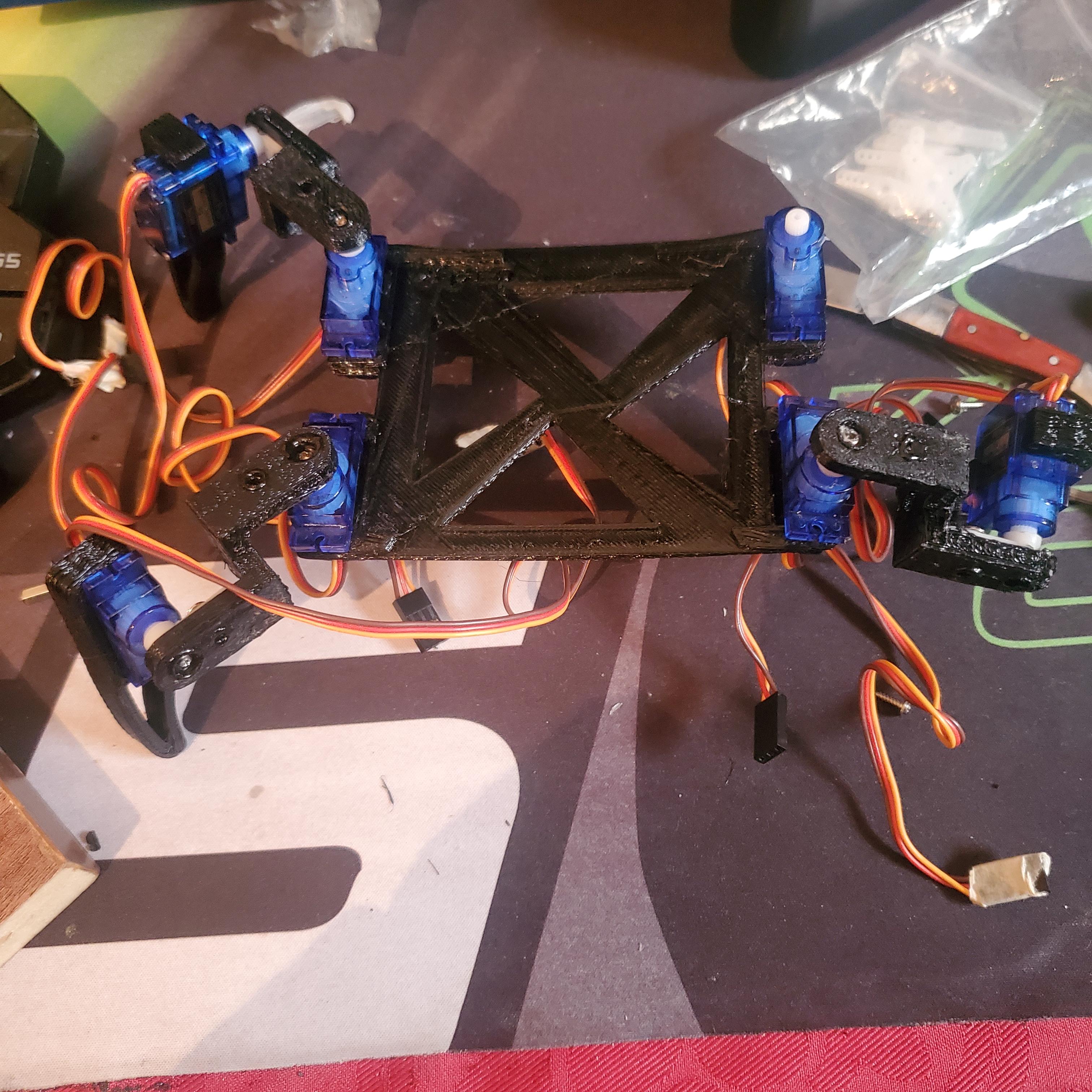
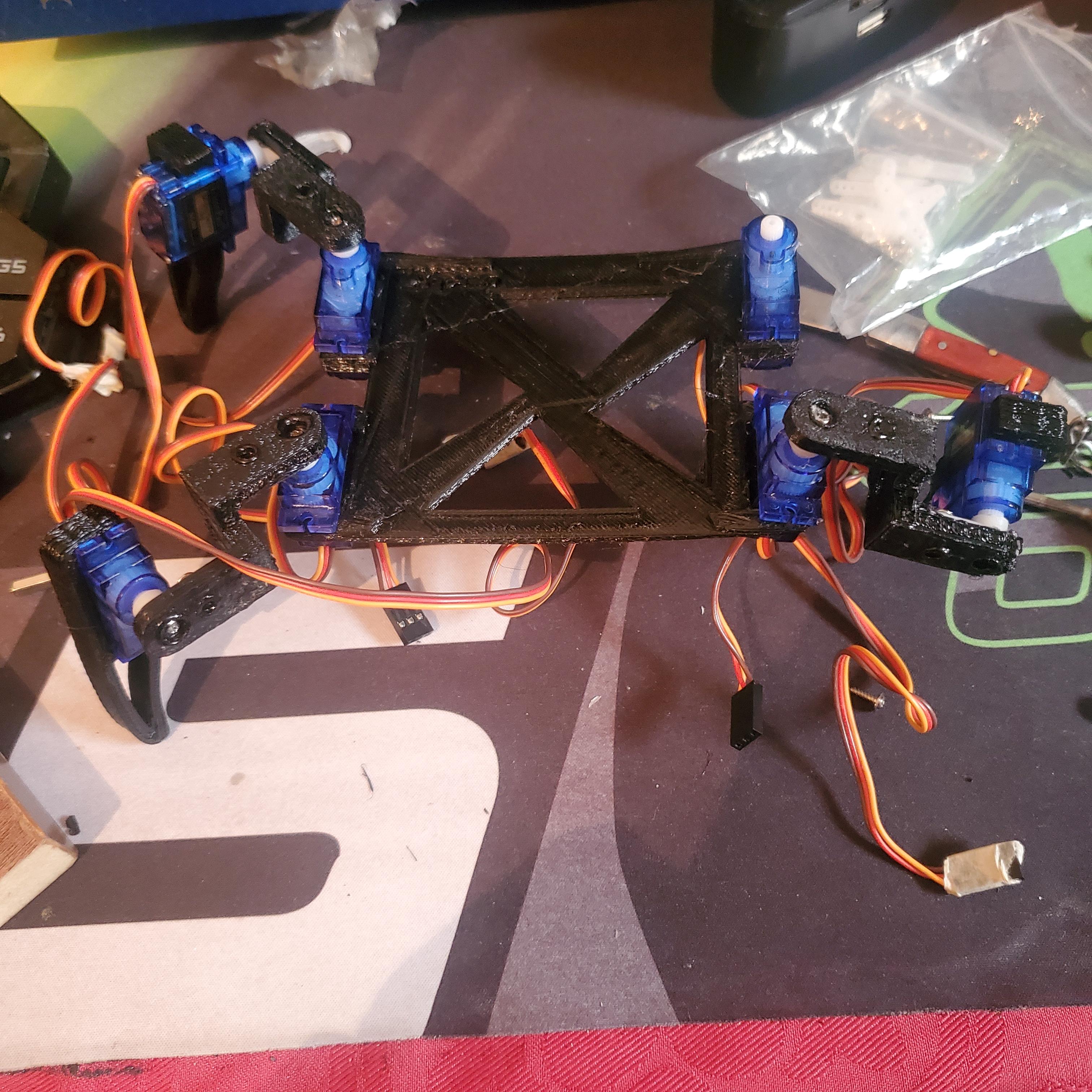
3. Connect Legs to the Main Frame:
- Upper Servo Placement: Attach the legs to the frame by securing the upper servo motors to the designated slots on the 3D-printed frame.
- Ensure Proper Alignment: Make sure the legs are aligned properly so that they can move freely without obstruction.
4. Wiring the Servos:
- Route the Wires: Carefully route the servo wires from the legs to the central area where your control board (e.g., ESP8266) will be placed.
- Secure Wires: Use small ties or clips to secure the wires, preventing them from getting tangled during movement.
5. Final Assembly:
- Test Movements: Before finalizing the assembly, manually move the legs to ensure that all parts are moving as expected.
Downloads
Wiring
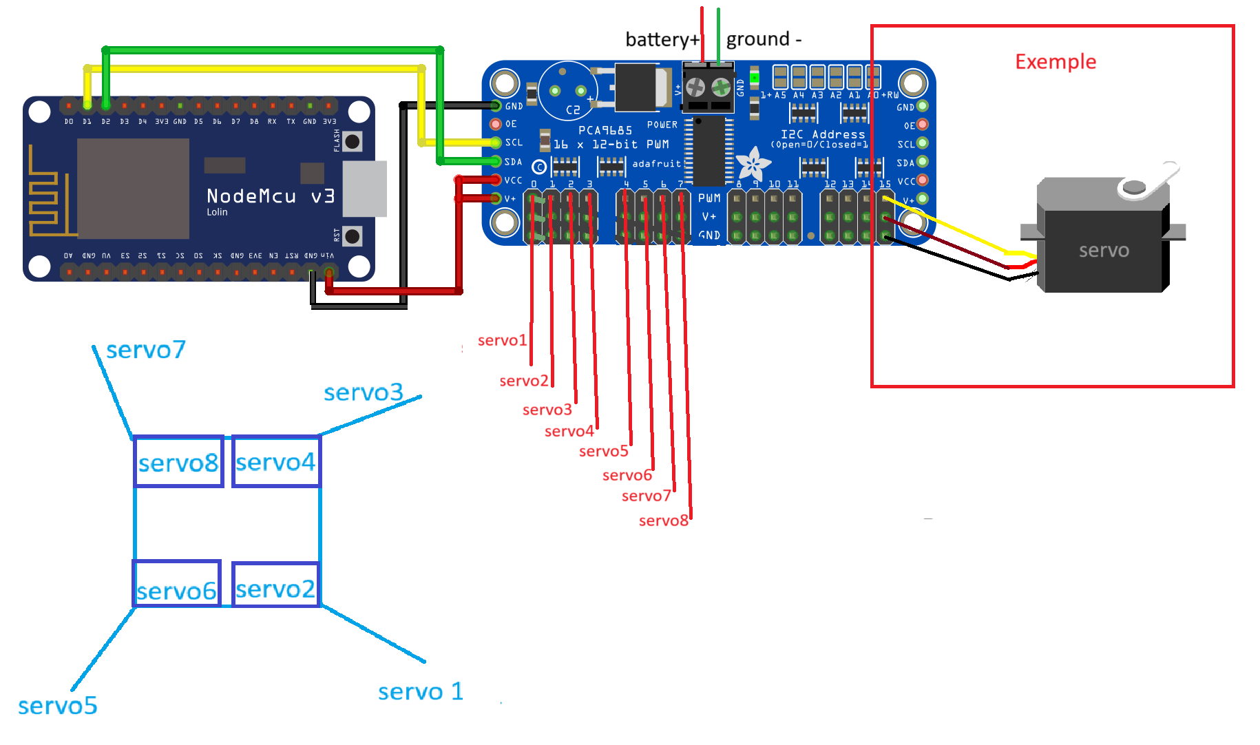
Connect the NodeMCU to the PCA9685:
- SCL Connection:
- Connect the SCL pin on the NodeMCU (D1) to the SCL pin on the PCA9685.
- SDA Connection:
- Connect the SDA pin on the NodeMCU (D2) to the SDA pin on the PCA9685.
- VCC Connection:
- Connect the 3.3V pin on the NodeMCU to the VCC pin on the PCA9685.
- GND Connection:
- Connect the GND pin on the NodeMCU to the GND pin on the PCA9685.
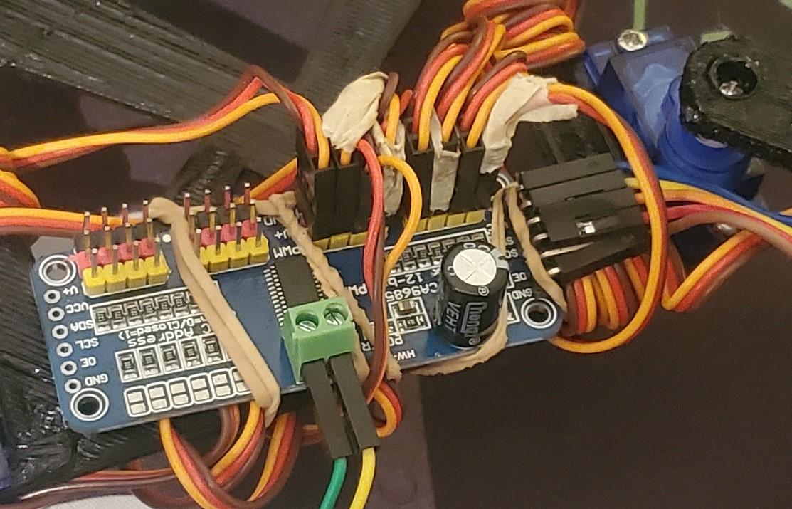
Connect the PCA9685 to the Servos:
- PWM Output to Servos:
- Connect each servo's signal wire (usually yellow or white) to the corresponding PWM output pins on the PCA9685.
- Example: Connect Servo1's signal wire to the PWM output 0 on the PCA9685, Servo2 to PWM output 1, and so on up to Servo8.
Power the PCA9685 and Servos:
- Battery Pack Connection:
- Connect the positive terminal of the battery pack to the V+ terminal on the PCA9685.
- Connect the negative terminal of the battery pack to the GND terminal on the PCA9685.
- This will power the servos through the PCA9685.
Final Checks:
- Double-Check Connections:
- Ensure all connections are secure and correct according to the wiring diagram.
- Verify that the SCL, SDA, VCC, and GND connections between the NodeMCU and PCA9685 are correctly placed.
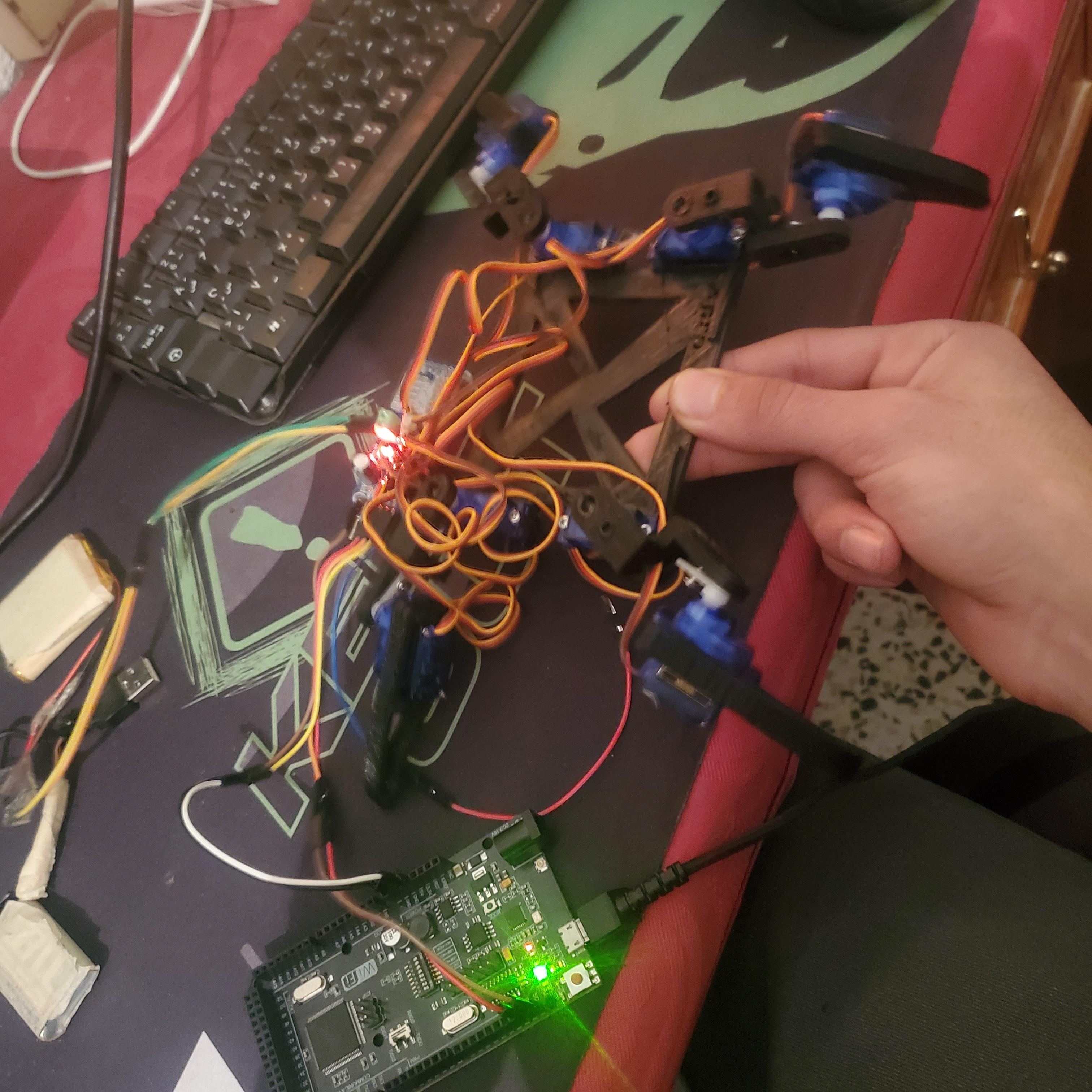
- Test Servo Movement:
- Power up the NodeMCU and test the servo movements to ensure everything is functioning as expected.
Upload and Test the Code
Upload Code:
- Use the Arduino IDE or another suitable platform to upload the control code to the card.
"Make sure to install the necessary libraries, such as Wire.h and Adafruit_PWMServoDriver.h."
Test Movements:
- Test each servo to make sure it moves correctly in response to commands from the card.
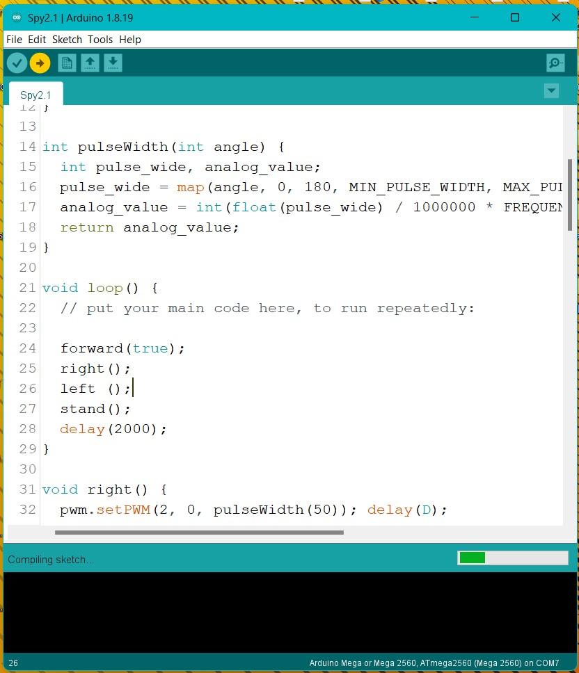
Movement Functions:
- right(): Moves the robot to the right by sequentially setting different servos to specific angles.
- left(): Moves the robot to the left in a similar fashion.
- stand(): Positions all servos so the robot is in a standing position.
- forward(): Continuously moves the robot forward while the condition x == true is met.
. Key Points:
- Each movement function (right, left, forward) sets specific servos to calculated PWM values that correspond to desired angles, thereby controlling the robot's legs.
- The sequence of servo movements in each function is crucial for the correct locomotion of the robot.
- The delay (delay(D)) between each servo movement allows the servos to reach their positions before the next command is executed, ensuring smooth motion.
Next Steps:
- Testing: Upload the code to the card and observe the robot’s movements to ensure the functions perform as expected.
- Adjustments: Modify the D value to change the speed of movements or tweak the angles in the pulseWidth() function for different gait styles.
- Further Development: Add more functions for additional movements or refine the current ones for smoother operation.