Sphero Gauntlet
Materials:
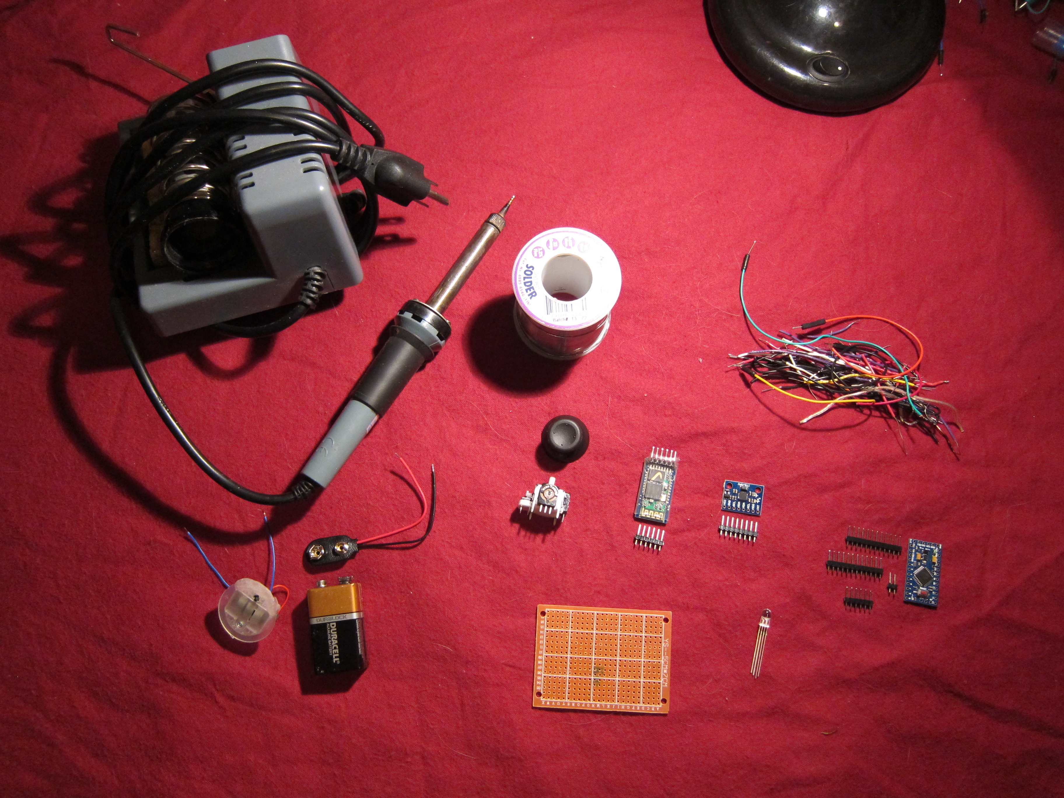
Sphero (note: testing was done with a Sphero Original; code has not yet been tested with Sphero 2.0)
Ardunio ProMini + FTDI cable (Nano should work but you'll need to modify the layout) + 6 extra header pins
1 Thumbstick/Joystick switch + Thumbstick cover
1 RGB LED + resistors to balance colors (I used a 5mm common anode LED with 2k(R), 10k(G), 5.1k(B))
1 GY-521 gyro/accelerometer
1 HC05 bluetooth module (mine had six pins in the order: LED, KEY, Rx, Tx, Gnd, Vcc. Not all HC05 modules are laid out the same, so either make sure you get one laid out as above, or take care to modify the wiring to match the different pins)
1 small perfboard. Should be able to fit it on the back of your hand (I used a 2"x2.75" with 18x24 holes)
1 9V battery + connector + on/off switch
Soldering iron, solder
Wire
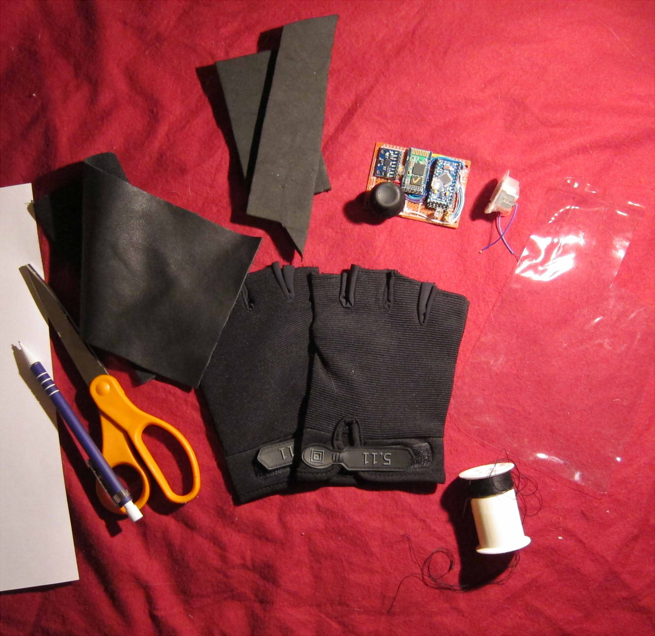
1 glove
Craft foam or other padding
Leather, vinyl, or other material to form housing
Clear, flexible plastic sheet (optional)
Small piece of velcro, or a snap fastener
Scissors, pencil, paper
Glue gun+hot glue
Needle & thread (you might be able to hot glue this together, but sewing will be way more durable)
Downloads:
Jeff Rowberg's I2Cdev and MPU6050 libraries
Paul Stoffregen's AltSoftSerial library
Gauntlet code pack (includes code from Cruz Monrreal's Arduino Sphero Libraries) - Zip file attached
Downloads
Step 1: Layout
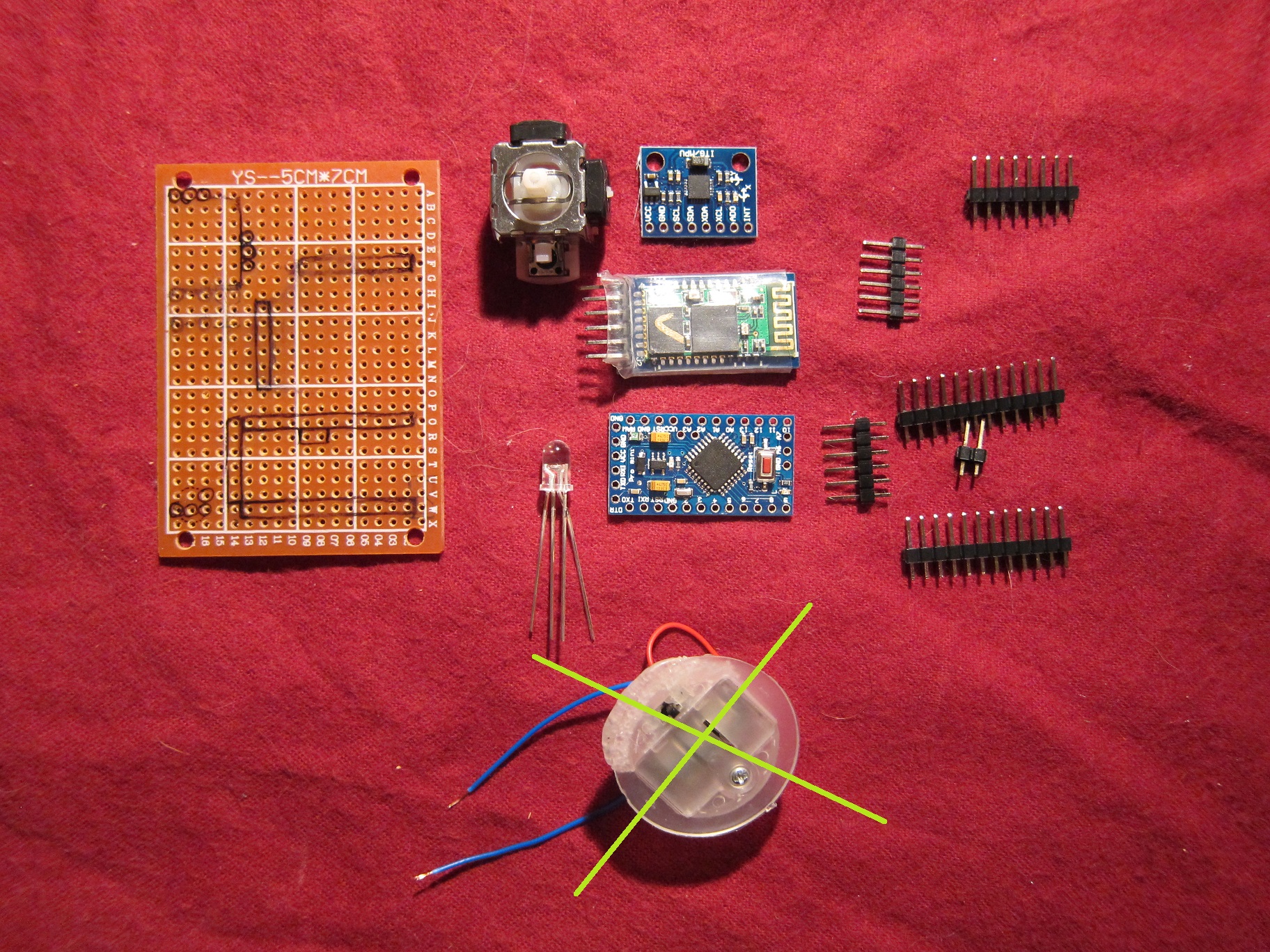
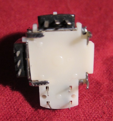
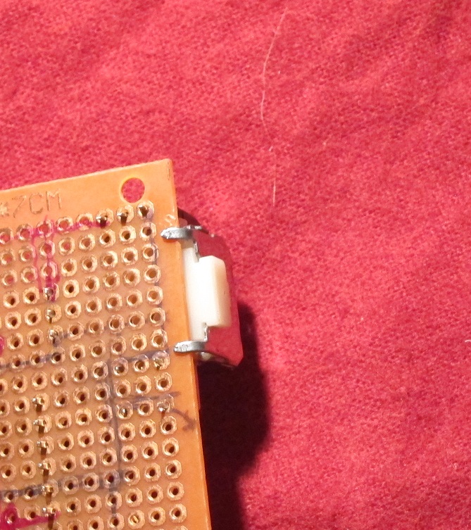
Place all your components. Draw markers for the header pins.
Notes on placing components:
If you're using an FTDI cable, add an extra row of pins next to the 6 pins used for programming. This way, you'll have something to attach the cable to after you've soldered in the Arduino
You'll need to cut, bend, or drill holes for the legs of the thumbstick switch to make it lie flat. I placed it so that the legs one side (the right side, from the bottom) hang over the side, to save space.
If you place anything very close to the thumbstick switch, put the cover on, swivel it around to check that it doesn't hit any nearby components.
If you use the above layout, place the LED farther up to leave room for resistors (better placement shown once I realized this, in step 4)
Step 2: Solder Headers
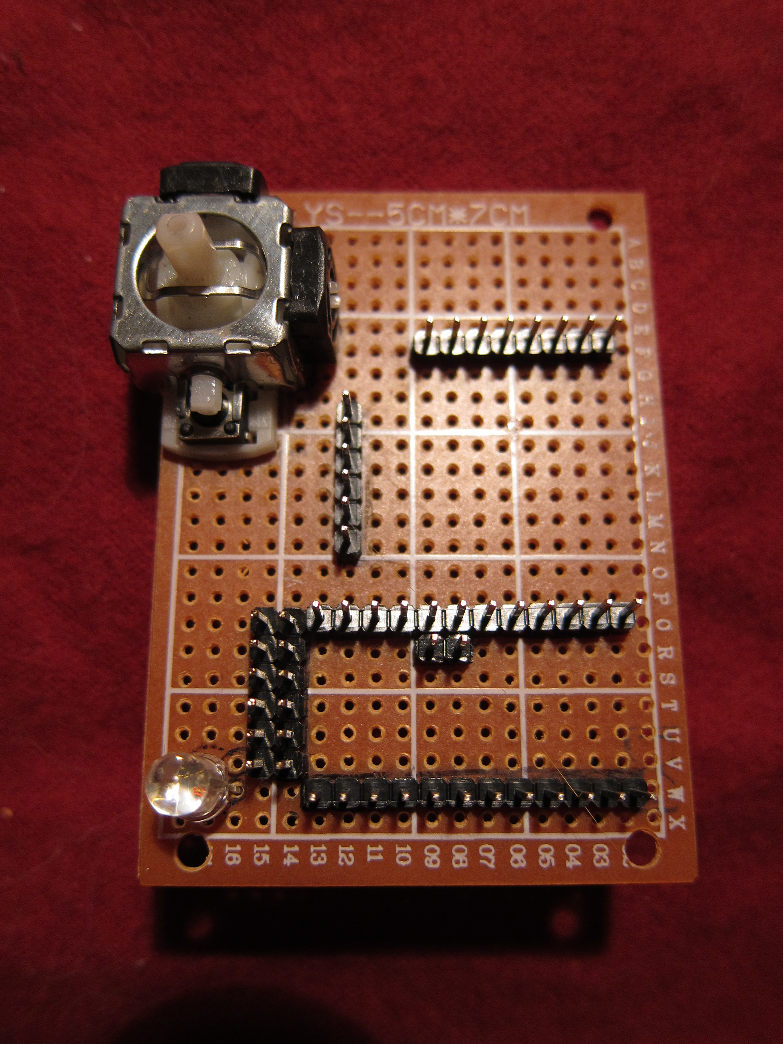
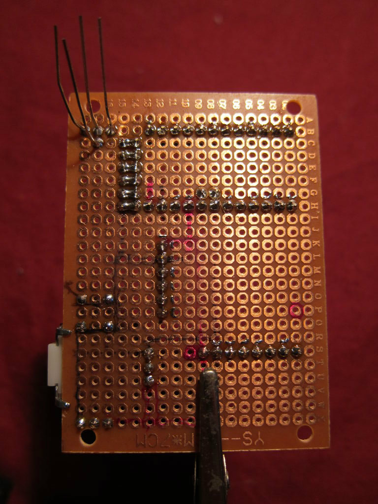
Double check your layout and solder those header pins
Bridge the programming headers to the extra headers. One side will be soldered to the Arduino directly, the other will be a connector for the FTDI cable.
Make sure to put headers for pins A4 and A5 of the Arduino; we'll need them for the I2C link to the accelerometer.
(Also I mentioned before, that LED is too low to leave room for the resistors, and should really be 3 or more pins higher)
Step 3: Solder Power and Ground Lines
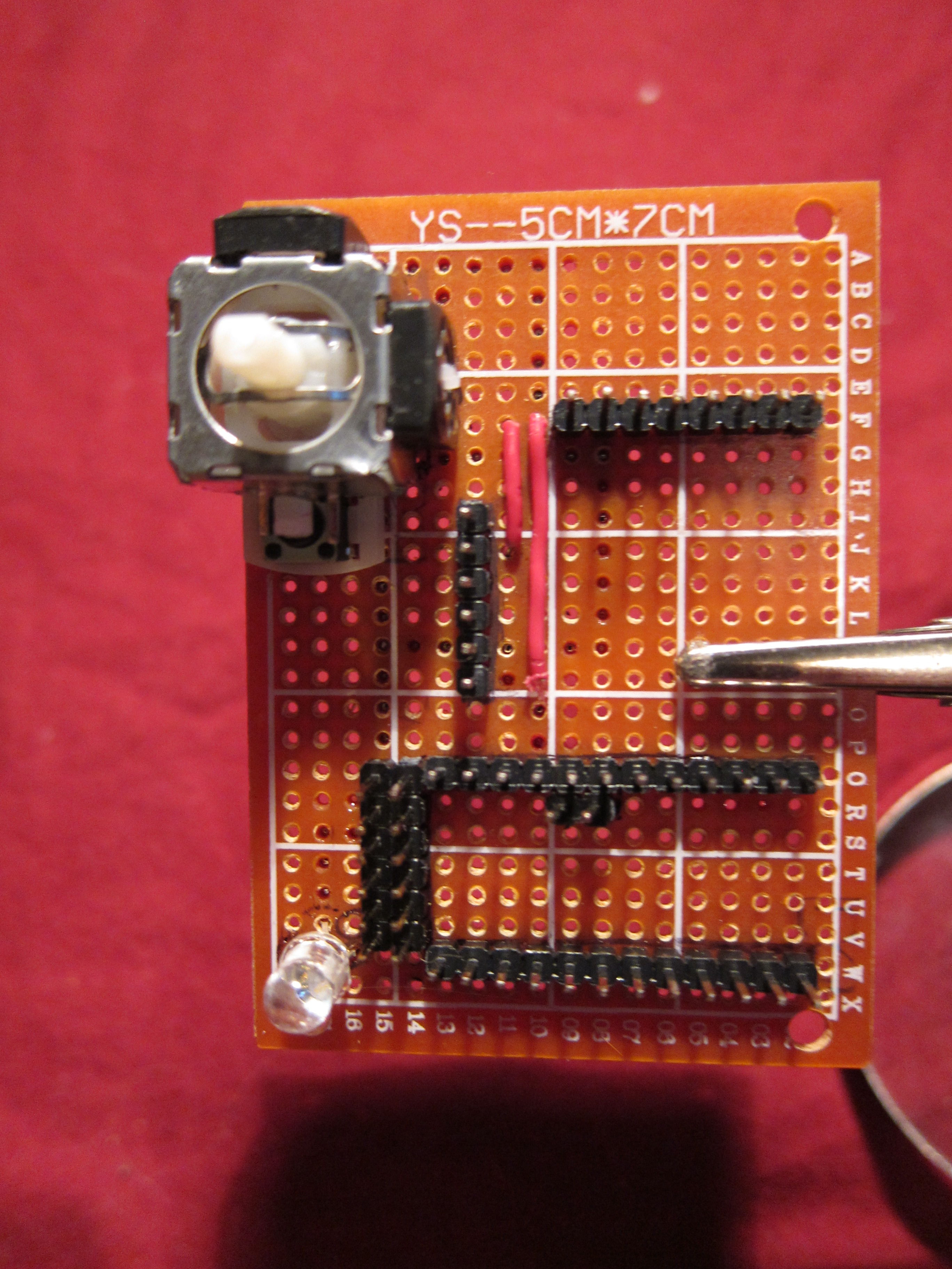
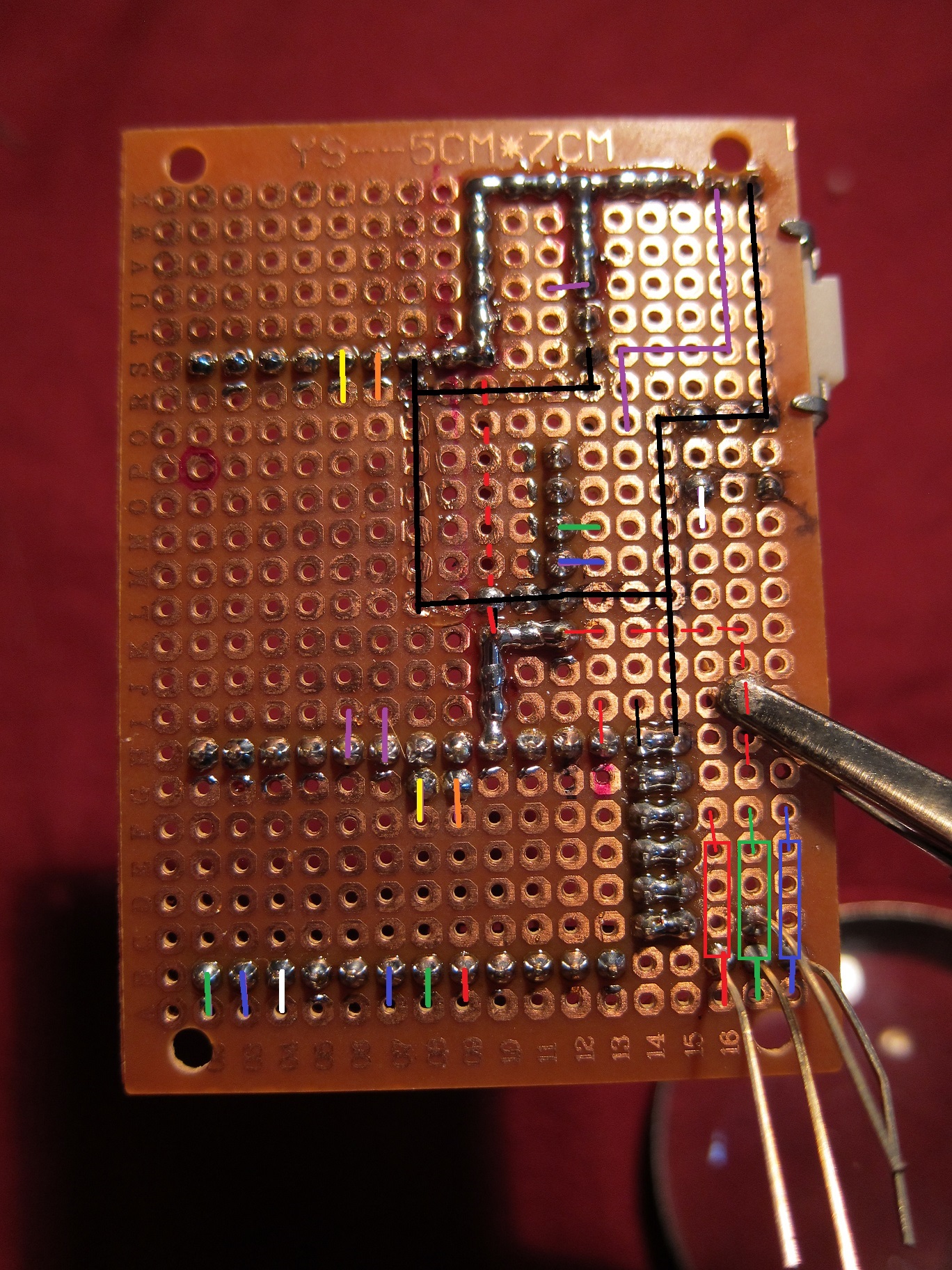
Solder all your power lines. Make sure that both joystick pots, the accelerometer, Bluetooth module, and LED anode are all connected to Vcc (as a side note, Vcc on the programming pins is not powered when the board is powered from the side-- don't connect anything important to it)
Next, solder your ground lines (drawn in black). Connect both joystick pots, the joystick button, accelerometer, Bluetooth module.
Step 4: Solder Signal Wires
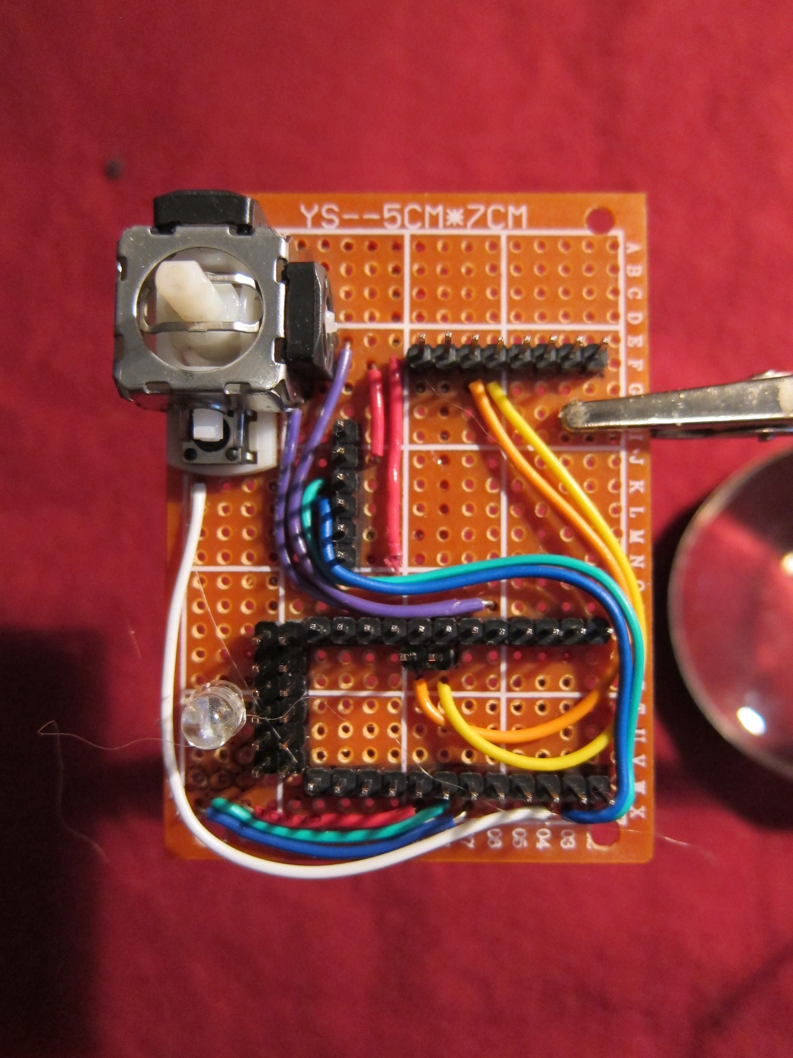
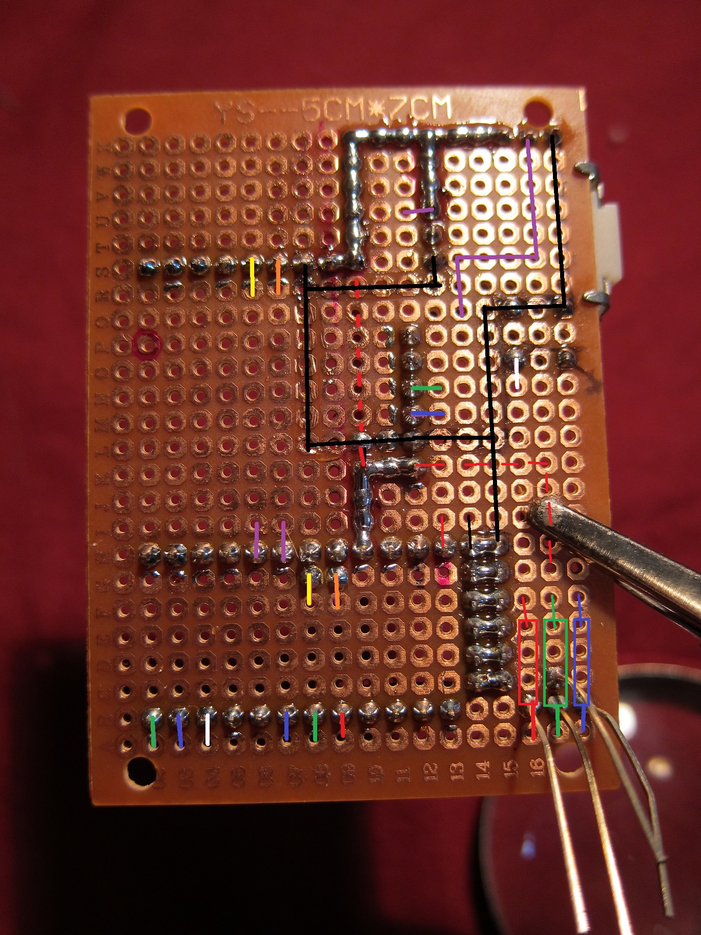
Wire the following connections (colors refer to wiring shown in the photos):
Accelerometer SCL to Arduino A5 (orange)
Accelerometer SDA to Arduino A4 (yellow)
Bluetooth KEY to Vcc (red)
Bluetooth Rx to Arduino D9 (blue)
Bluetooth Tx to Arduino D8 (green)
Joystick horizontal potentiometer signal to Arduino A1* (purple)
Joystick vertical potentiometer signal to Arduino A0* (purple)
Joystick button signal to Arduino D7 (white)
*vertical is on the side, horizontal is on the top. Don't worry about accidentally swapping them, you can swap the pin assignments in code.
Step 5: Solder LED
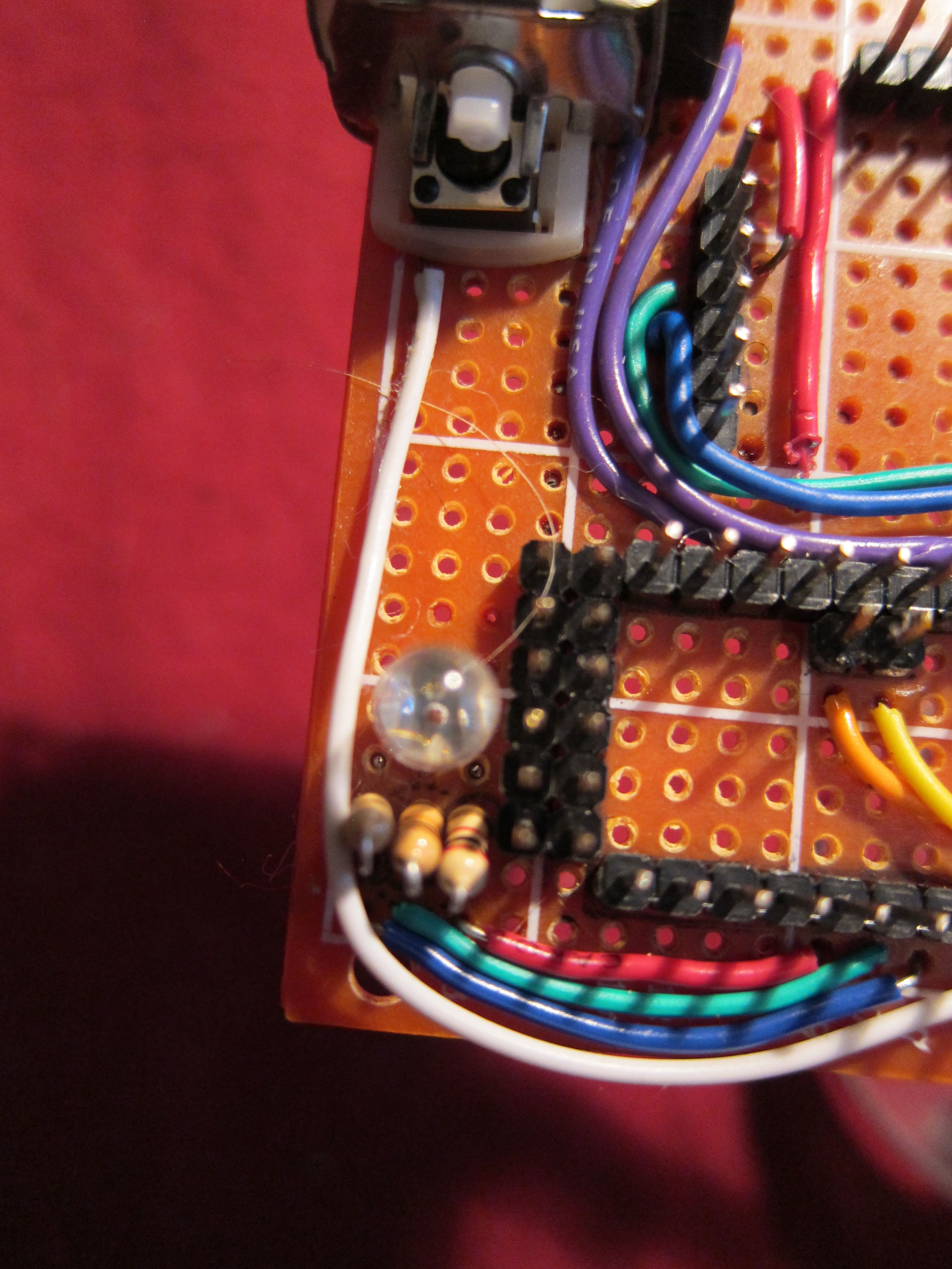
Find resistors to balance the colors of the RGB led such that you get clear intermediate colors (yellow, teal, purple) and white. My selections were 2k (red), 10k (green), and 5.1k (blue). Solder the LED leads to the resistors, and wire the resistors to the following pins.
RGB Red to Arduino D2 (red)
RGB Green to Arduino D3 (green)
RGB Blue to Arduino D4 (blue)
Wire the LED anode to Vcc (the one on the side of the board).
Step 6: Solder Arduino to Headers, and Check Solder Connections
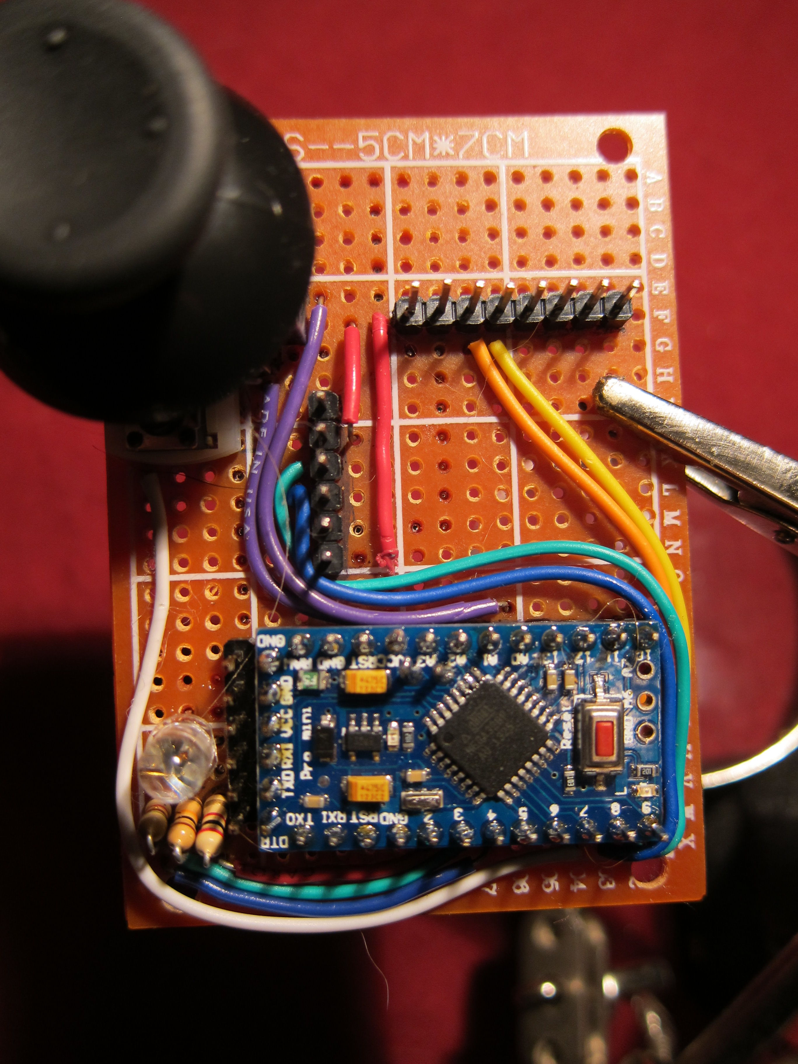
Solder Arduino pins to headers. Make sure you also solder pins A4 and A5.
Check all pin-to-pin connections. Check that power and ground are not bridged.
Step 7: Begin Testing Software, Calibrate the Joystick
Download and place I2CDev, MPU6050, AltSoftSerial, and the contents of Gauntlet_Pack in your Arduino libraries folder. (links are on the first page of this instructable)
Open or restart the Arduino IDE.
From the Sphero examples, select JoystickRaws.
Connect your circuit and upload the program. Open the serial window and set the baudrate to 9600. The program will first test your connections on the three connected pins (two analog, one digital). If all is well, the program will proceed to print out any uncommented raw values, which you can use to calibrate.
To calibrate:
Uncomment the "getAngle()" function, disable the rest
Upload the program.
First, move the toggle until you find 0. The target is a zero response when the toggle is pushed to the right. If your zero is up or down, go into the Gauntlet_Joystick.cpp file and swap the pins for HORIZONTAL_POT and VERTICAL_POT. Save and re-upload the program.
Find 0 again. If it is on the left side instead of the right, go into Gauntlet_Joystick.cpp and set the HORIZONTAL_SWAP boolean to "true".
Now find 90. If it's to the bottom, go into Gauntlet_Joystick.cpp and set the VERTCAL_SWAP boolean to "true". Save and re-upload the program.
At this point you should get 0/359 to the right, 180 to the left, 90 up, and 270 down.
Now, from the Sphero examples, select JoystickEvents and upload it. Open the Serial window.
If everything was working in the previous step, the program should echo your actions in text.
Step 8: Check RGB LED
Select Sphero example RGBdebug and upload it. Open the Serial window.
If your LED is connected correctly, you should be able to select between the primary and secondary colors, white, and off by entering a capital letter corresponding to the color. If you have a common cathode LED, you'll need to change the color definitions from 0-7 to 7-0 (WHITE = 7, YELLOW = 6, etc.)
When all the solid colors are displaying properly, try blinking the LED by entering lower case 'b', or flashing the last three colors entered by entering 'f'. The latter is used in the main program to display the Sphero's three-color-id, while the former is used to indicate certain state transitions.
Step 9: Solder and Check Accelerometer
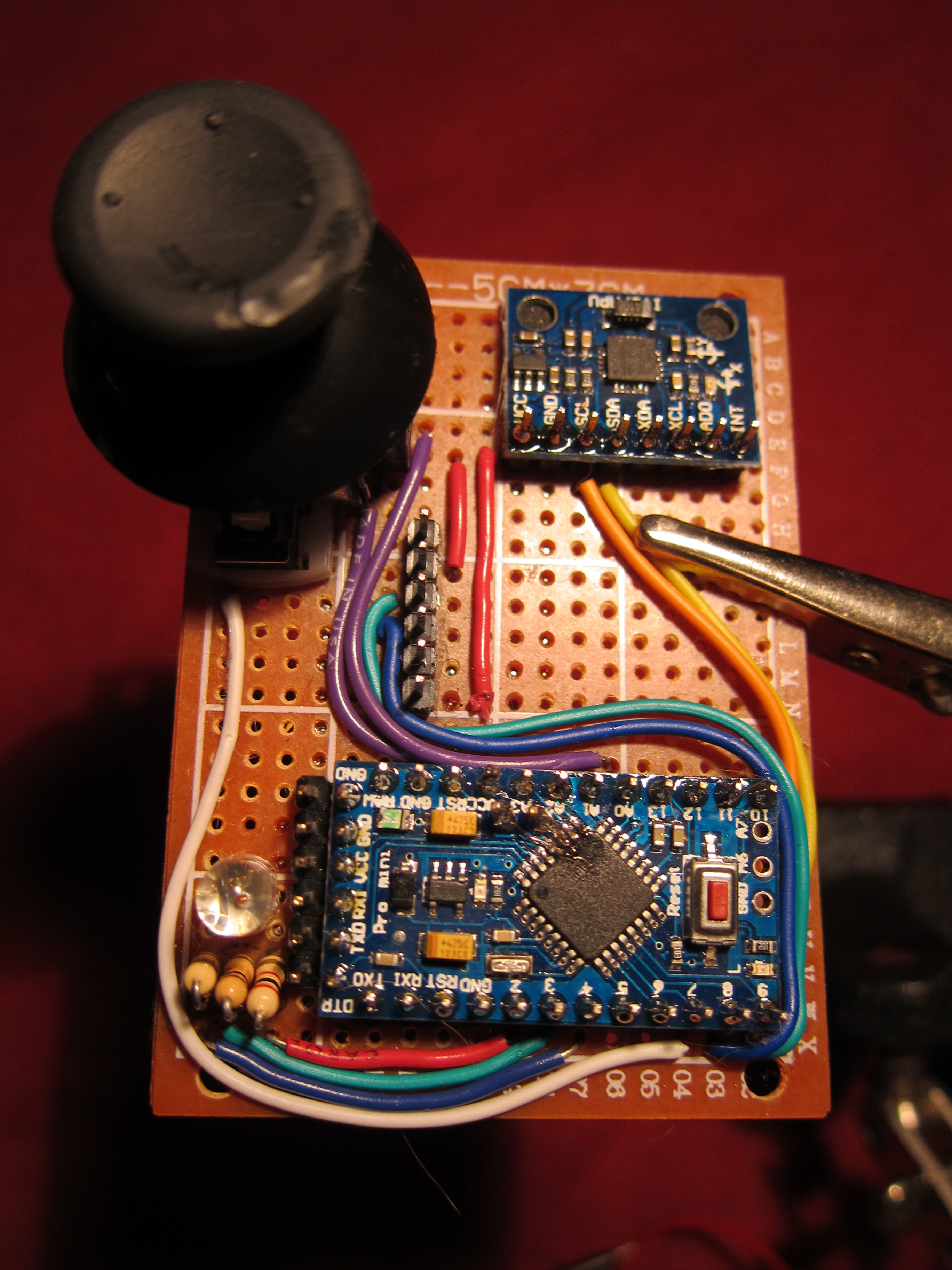
Solder accelerometer such that the pins are closer to the bottom of the board and the x axis is pointing to the top of the board.
In the Arduino IDE, open the "MPU6050_raw" program from the MPU6050 example menu. Change the Serial.begin(baudrate) in the sketch to 9600. Upload the program and open the Serial window.
The accelerometer and gyroscope data will print continuously. If you get all zeros, check your connections.
Once you're get proper sensor data, upload the "AccelerometerTilt" example from the Sphero menu.
The speed is calculated by the x-y-z tilt, where the speed is zero when the x-y plane is parallel to the floor. The heading is calculated using the y tilt/roll about the x axis, so that the Sphero is directed forward when the fingers of the glove are pointed down, to the side when the glove is sideways, and back toward the user when the fingers are up. Sphero's zero is forward (heading will be zero when fingers are down) and runs clockwise from there (heading = 90 when glove is tipped to the right, 180 when tipped back, and so on).
You can also enable the LED feedback block, to display colors as the heading changes (RED = forward, BLUE = back, YELLOW = right, GREEN = left)
Step 10: Solder and Check Bluetooth
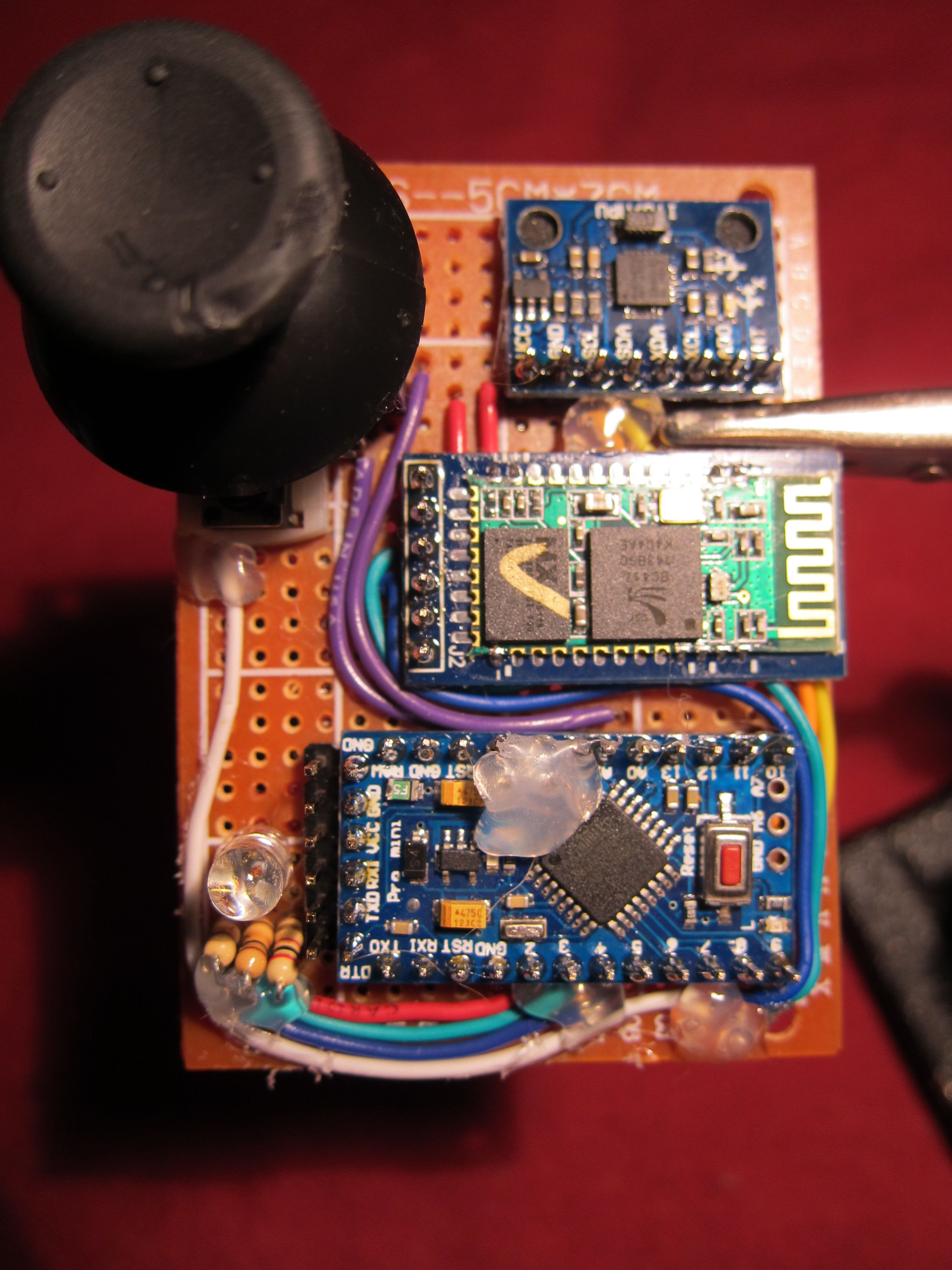
Solder Bluetooth module to board.
Run HC05_TransparentDebug example. Open Serial window. Set line ending to "Both CR & NL"
Type in "AT". Response should be "OK"
You can try other commands, but if the Bluetooth responds with OK you're set to proceed.
For more AT commands, see the HC05 instruction manual.
It is possible to link to the Sphero from this program using the AT+LINK=[address] command, but you will not be able to disconnect unless you cut power to the Bluetooth module, or upload the "AutoSleep" program.
Step 11: Test Sphero Connection
This step is to test some pieces of the main program individually. Note that the latter four require that the Sphero be connected to the gauntlet. (Sphero will remain connected over reset cycles, but will disconnect if the HC05 loses power)
AutoConnect: (modified from Cruz Monreal's AutoConfigBluetoothForSphero example) Automatically configures HC05 and connects to first Sphero it finds
SpinMeRightRound: (modified from Cruz Monreal's SpinMeRightRound example) Tests the gauntlet's ability to send commands. Sphero backlight should light up, and should begin to rotate.
Ping: Tests the gauntlet's ability to receive a simple response.
YawToHue: (modified from Cruz Monreal's YawToHue example) Tests the gauntlet's ability to collect and respond to asynchronous data packets. Sphero should change color according to its heading (by manually rotating the Sphero).
AutoSleep: sends the bytes for a 'sleep' command directly over the AltSoftSerial line. If sphero is linked to the gauntlet, uploading this program should turn it off even if other programs aren't working.
Step 12: Test Full Program
Upload SpheroGauntlet program.
LED colors/patterns indicate the following states:
Yellow: Initializing Device (cannot be interrupted)
Purple: Pinging Sphero. (Checks to see if Sphero is already connected. Cannot be interrupted)
Red: No devices found. (Click to scan)
Teal: Scanning. (Usually takes <10 seconds. If it's taking too long, click to retry)
Flashes 3-color ID: Device Found. (Click to select)
Blue Flash 3x: Attempting to connect to device.
Red Flash 3x: Connection attempt failed. (will return to 3-color flash/selection state. Click to retry)
Solid Blue: Rolling state/Connection established. (Click once to enter calibration state, twice to change Sphero color)
Green: Calibration state. (Use joystick to change heading. Click once or twice to re-enter Rolling State)
White: Color Select state. (Use joystick to change color. Click once or twice to re-enter Rolling State)
Flash Purple 3x: Disconnecting. (To get to this state, click and hold the joystick button for >3 seconds while in any of the previous three states)
Some parts of the connection sequence may take a few tries. If things aren't working, resetting or switching the gauntlet off and back on may fix it. Once the Sphero is connected, as long as you don't cut power to the bluetooth module the gauntlet will automatically enter the Rolling state if it's reset.
Step 13: Add Power Supply
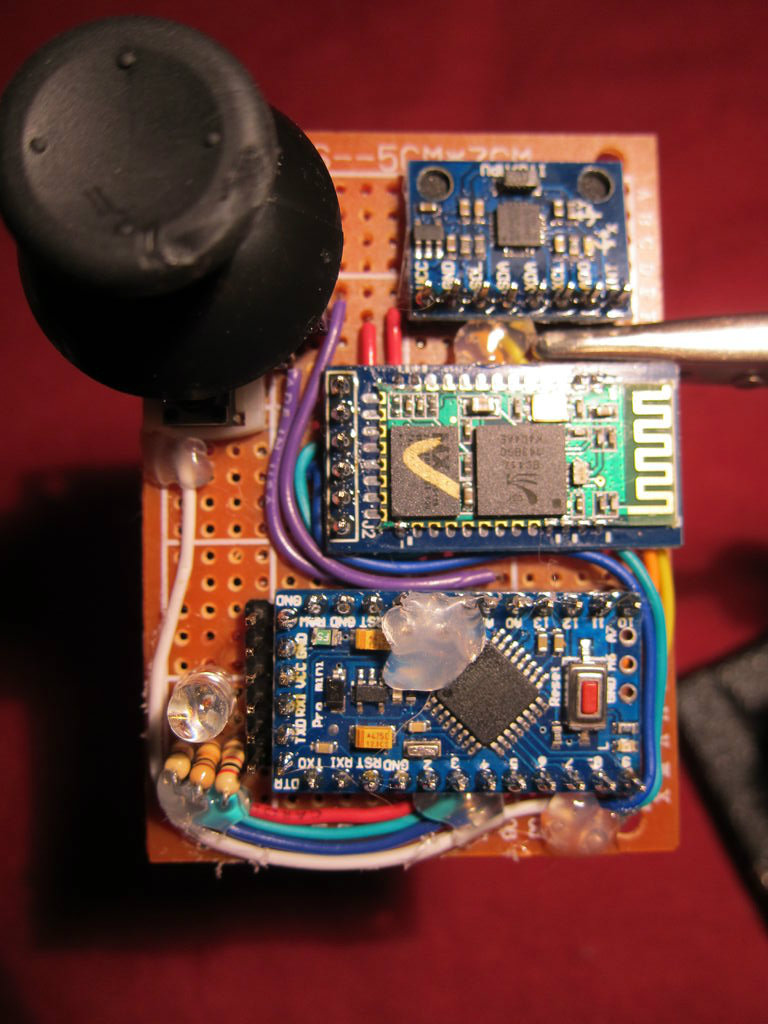
Connect switch to 9V battery. Connect 9V(+) directly to RAW pin of Arduino. Run through the program again, to make sure that things are still working as expected. (It should be fine with a 9V battery; I had trouble-the Bluetooth became unreliable when I tried to use coin cell batteries as a power source.)
At this point, assuming your circuit is working and you won't be making any changes to the wiring, you may want to use hot glue to reinforce connections or areas where the wires will be under stress.
Step 14: Collect Materials for Gauntlet
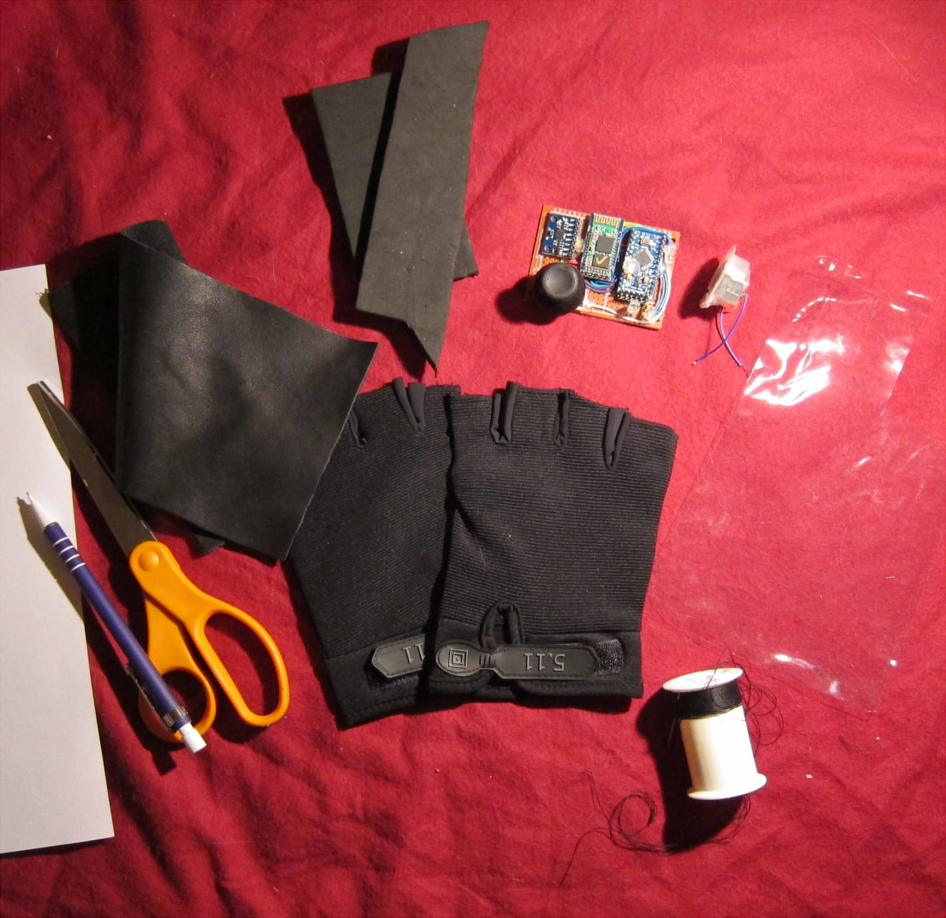
Moving on the the crafting part of this project, you'll need:
1 gauntlet circuit
1 glove
Craft foam for padding
Leather, vinyl, or other material to form housing
Clear, flexible plastic sheet (optional)
Scissors, pencil, paper
Velcro or snap fastener
Needle & thread (you might be able to hot glue this together, but sewing is advised as it will be more durable)
Step 15: Attach Circuit to Glove
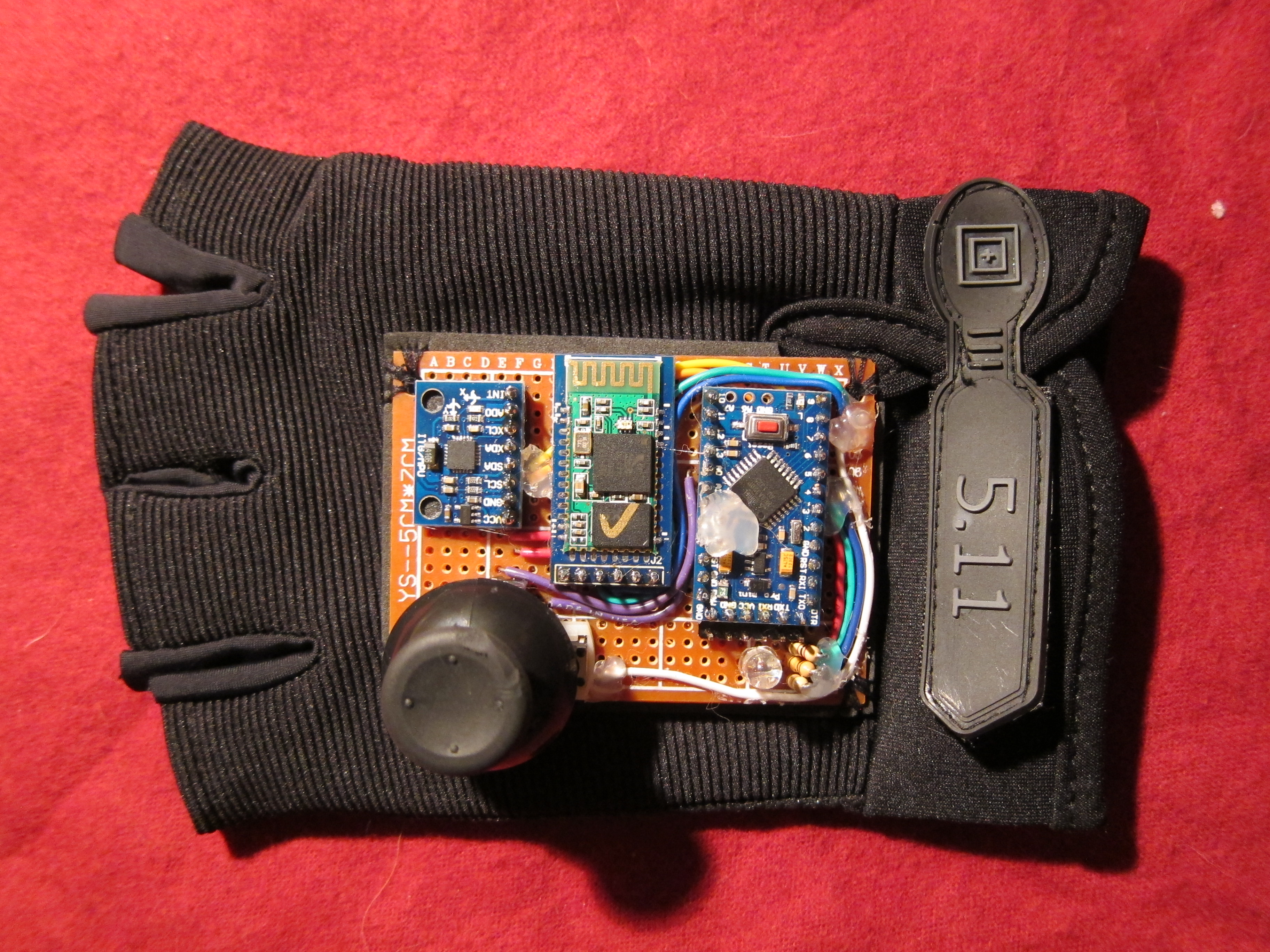
Place the circuit. You may want to place it while wearing the glove so it will sit comfortably.
Cut a piece of craft foam the size of your board and place it between the board and the glove.
Sew corners of circuit board firmly to glove.
Step 16: Make a Pattern for Circuit Housing
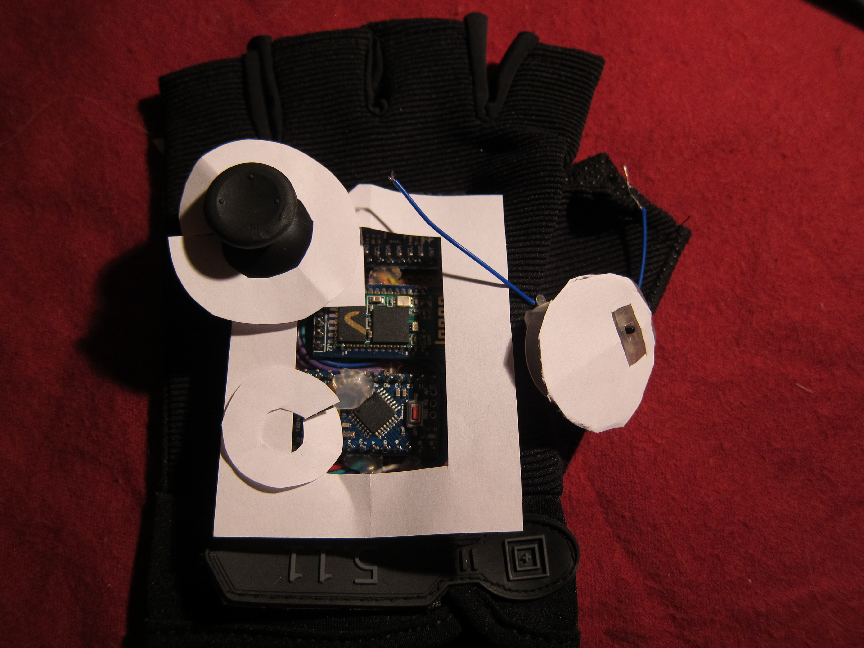
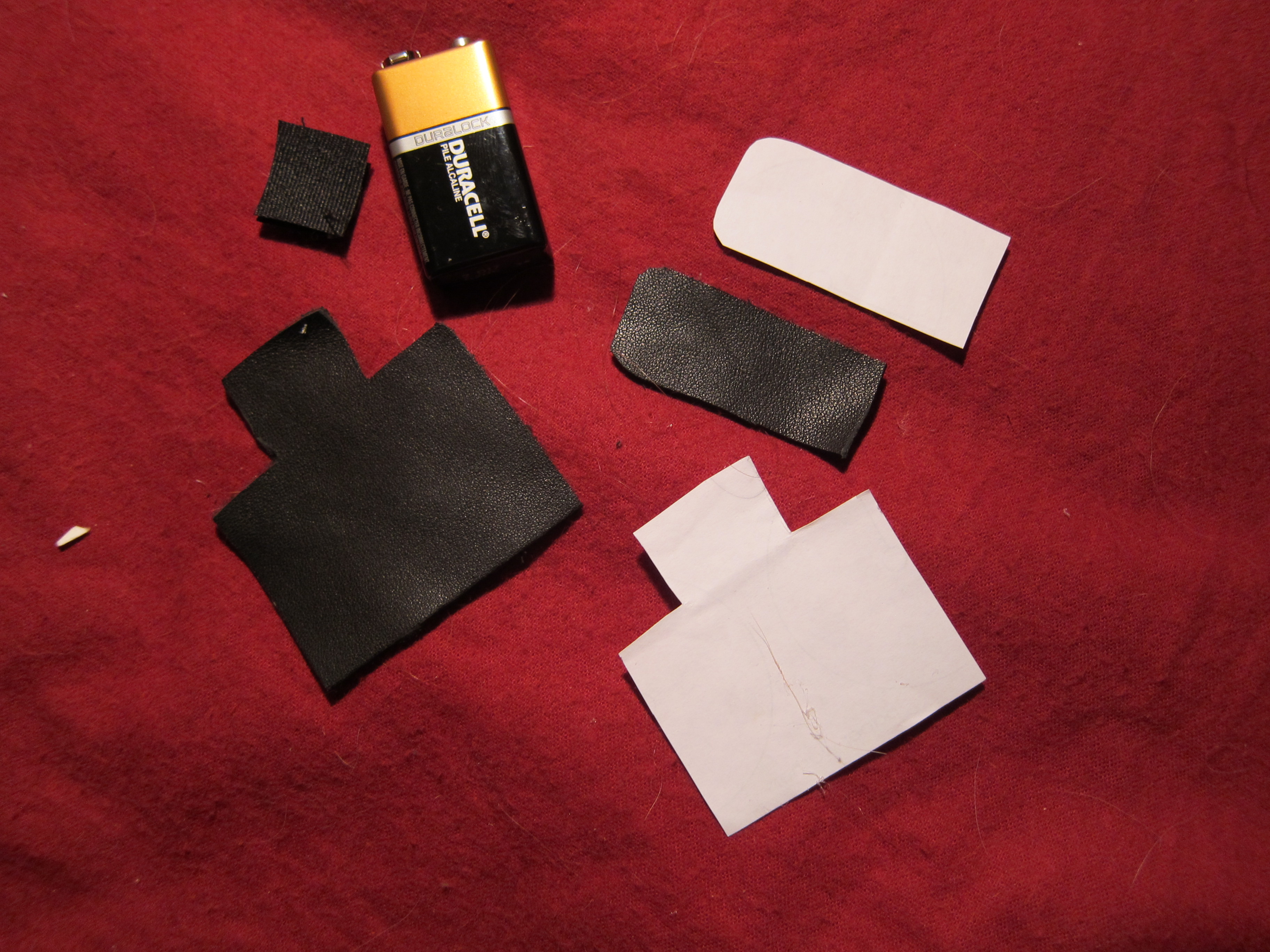
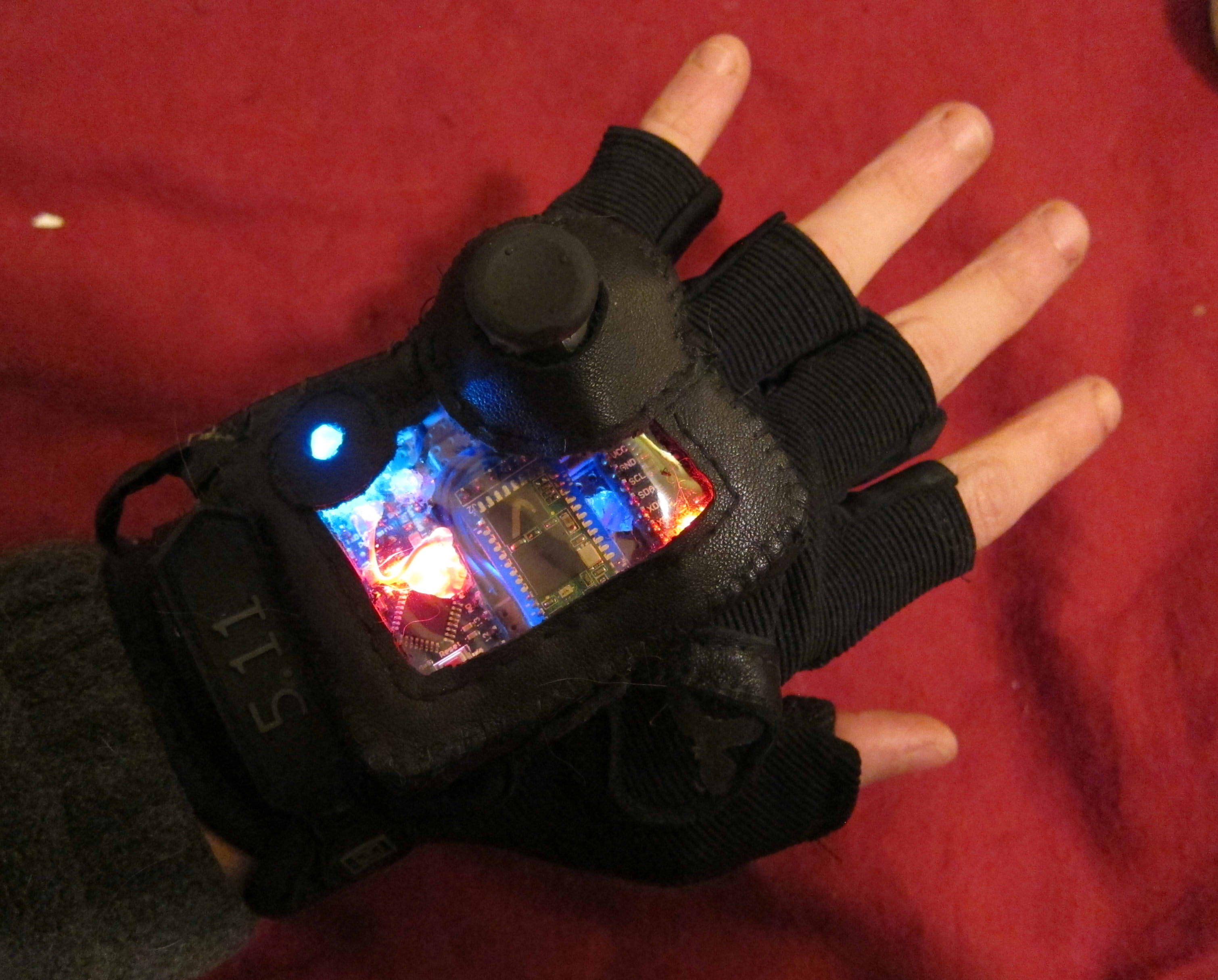
Figure out how you want to lay out your housing and create a paper template. I wanted a viewing window so I have a rectangular border for the main board, a circle for the LED and a circle for the Joystick. You will also need a long strip about 1/2" wide to form the walls of the housing. The battery pack will sit in a sleeve on the underside of the glove, with a flap and velcro to hold it closed.
Cut out your leather/vinyl pieces.
Step 17: Sew Top and Side Pieces of Housing
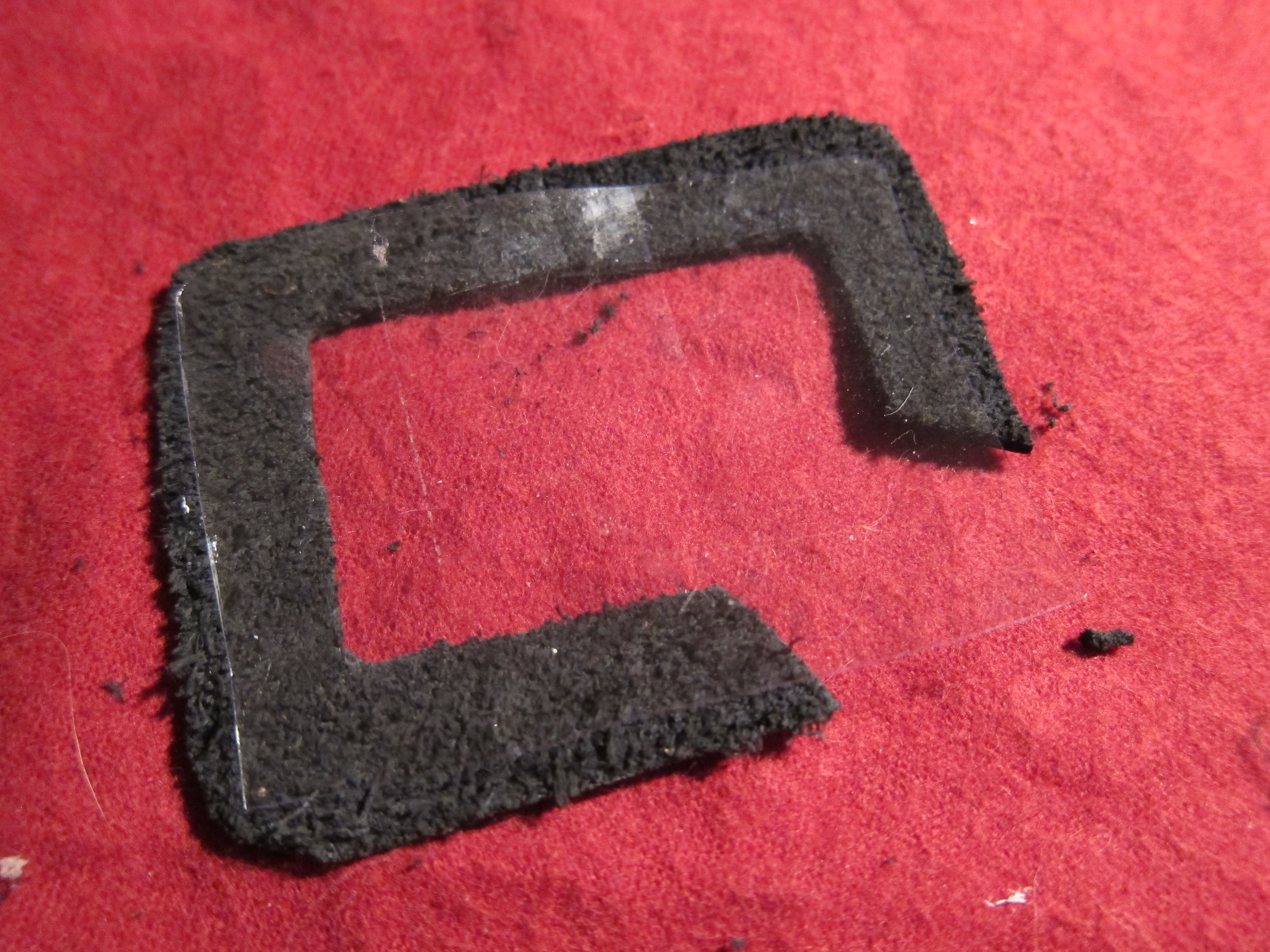
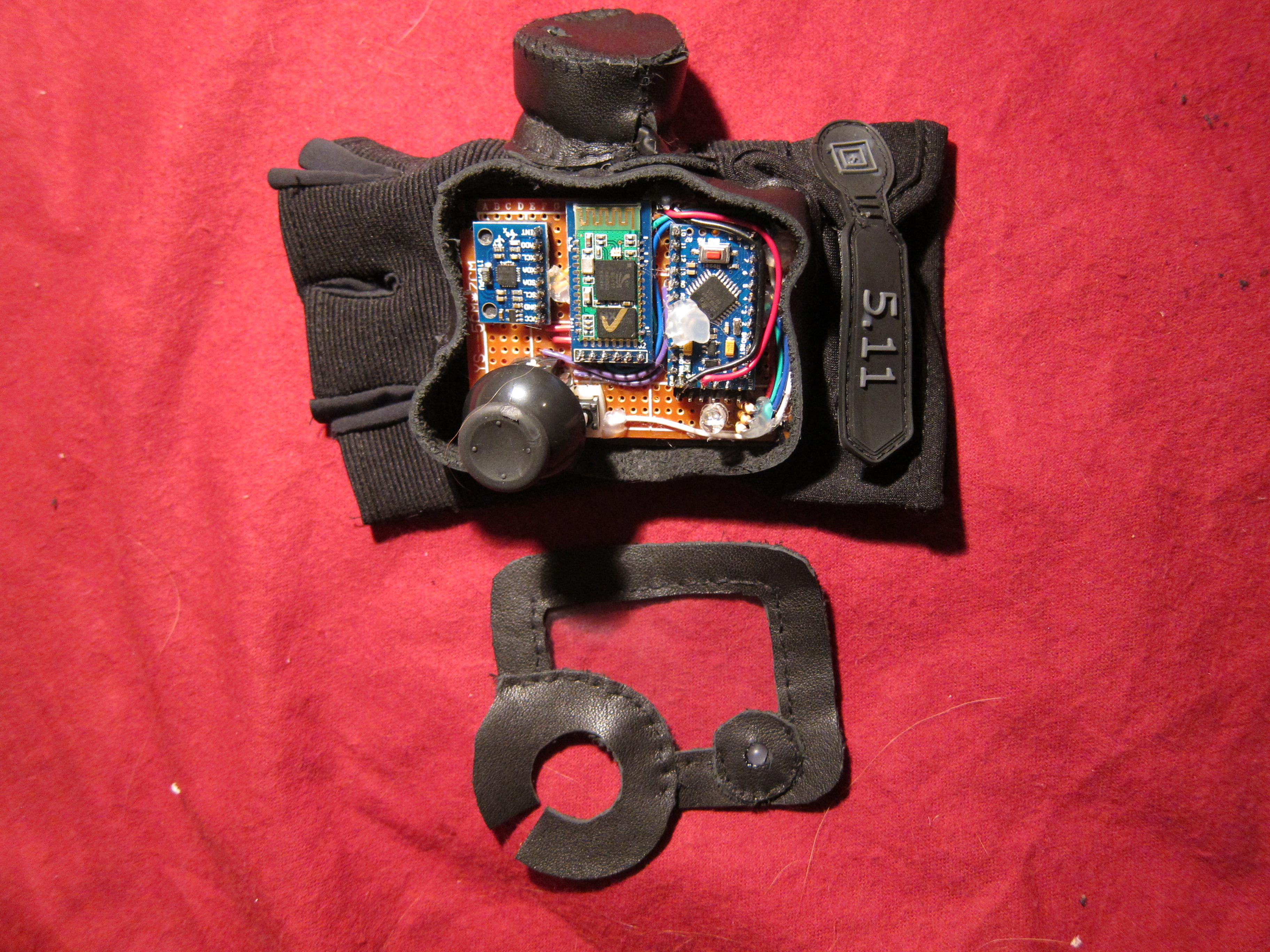
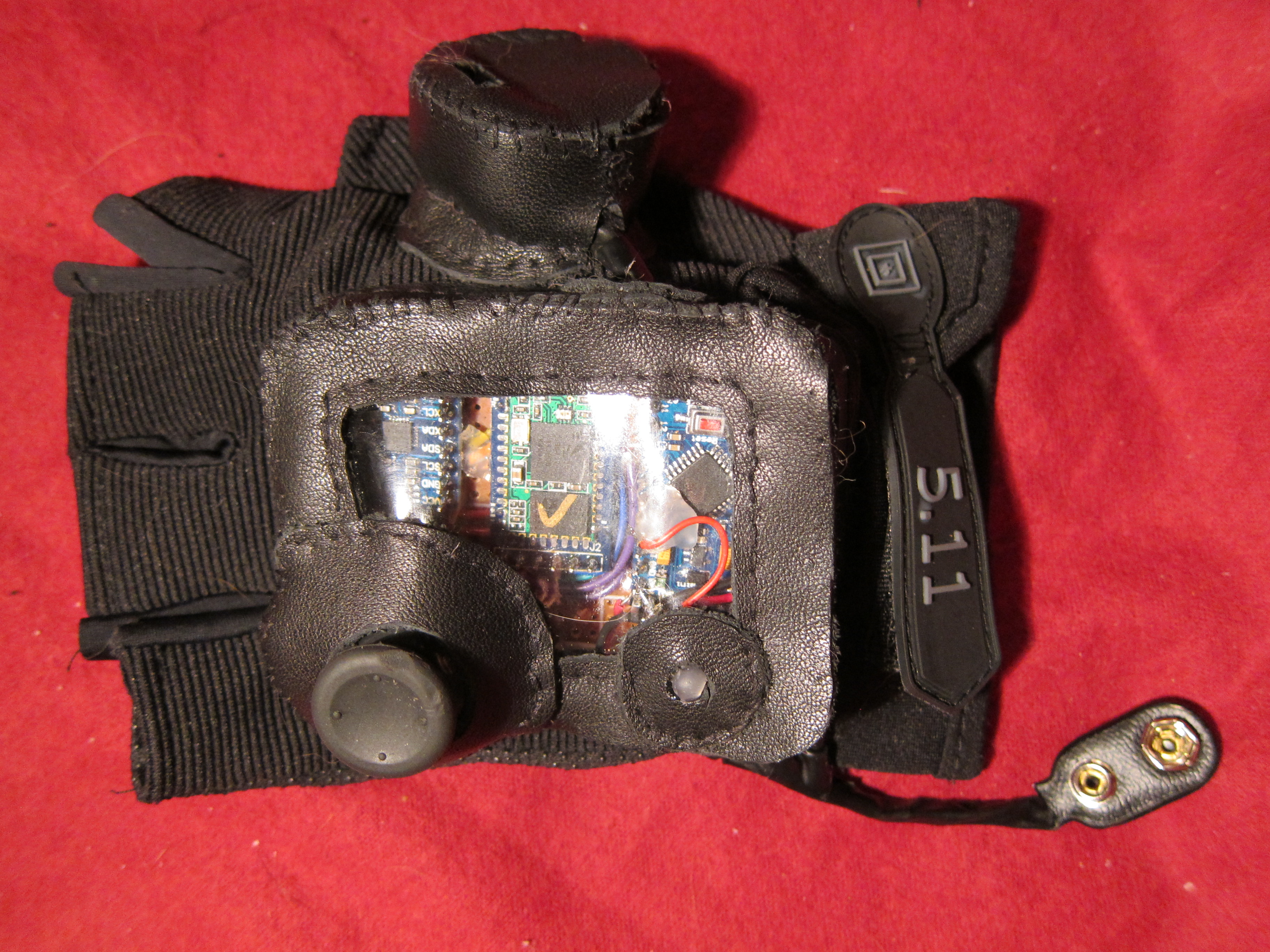
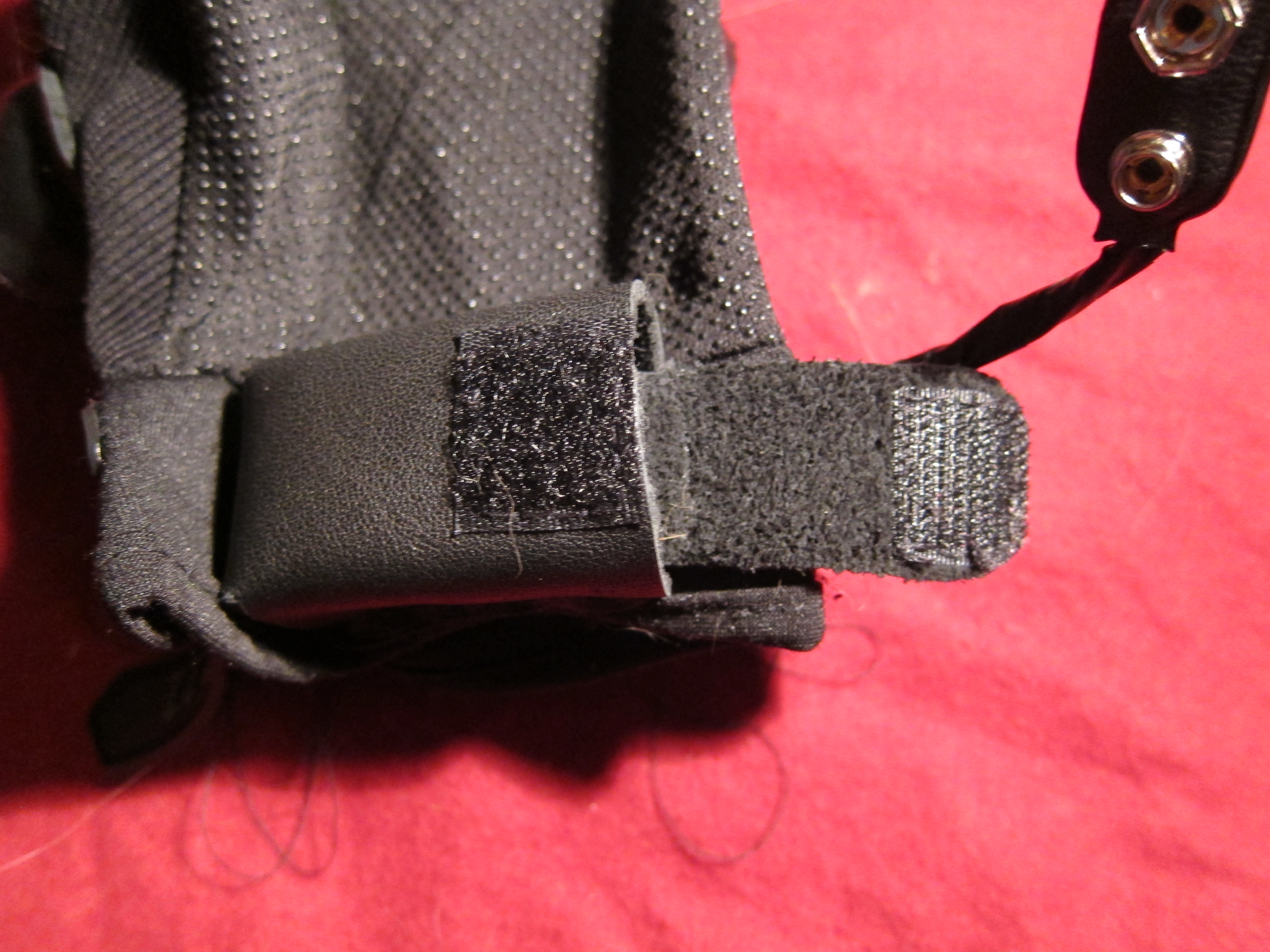
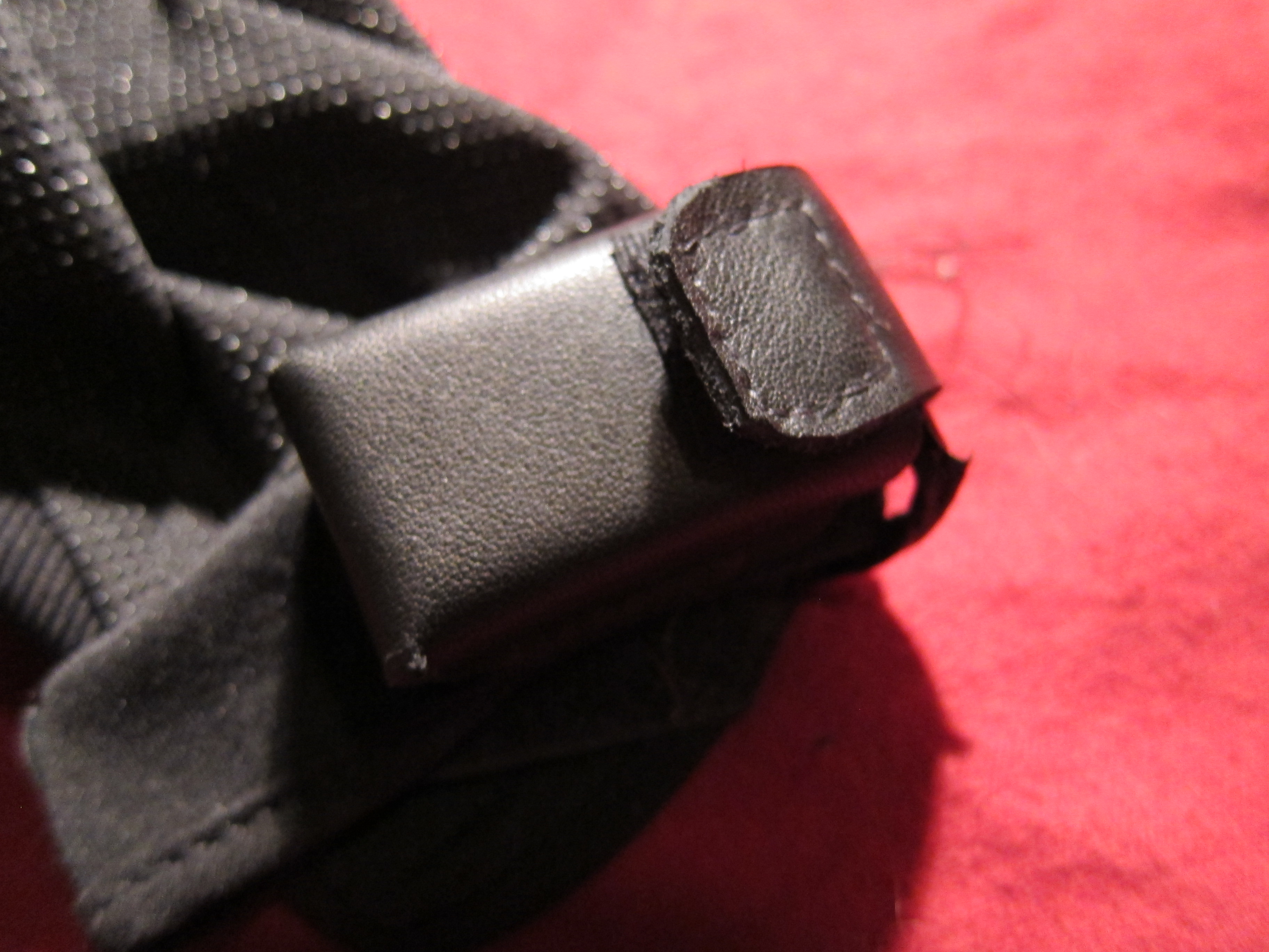
If you're using a viewing window, cut out a piece of the flexible plastic that is slightly smaller than the frame it'll be sitting in. Sew or hot glue along the edges.
Add the rings for the joystick and LED. Cut out any material (leather or plastic) that blocks the inner hole of either ring.
Make sure the strip for the side wall is exactly as long as the perimeter of your top piece.
Sew or glue the housing face to the side wall, then sew or glue the side wall to the circuit. (I did it in the opposite order and it was way more difficult than it had to be)
For the battery holder:
Sew velcro onto the cut pieces.
Sew holder and strap onto glove. Make sure that the velcro pieces meet up.
You're Done!
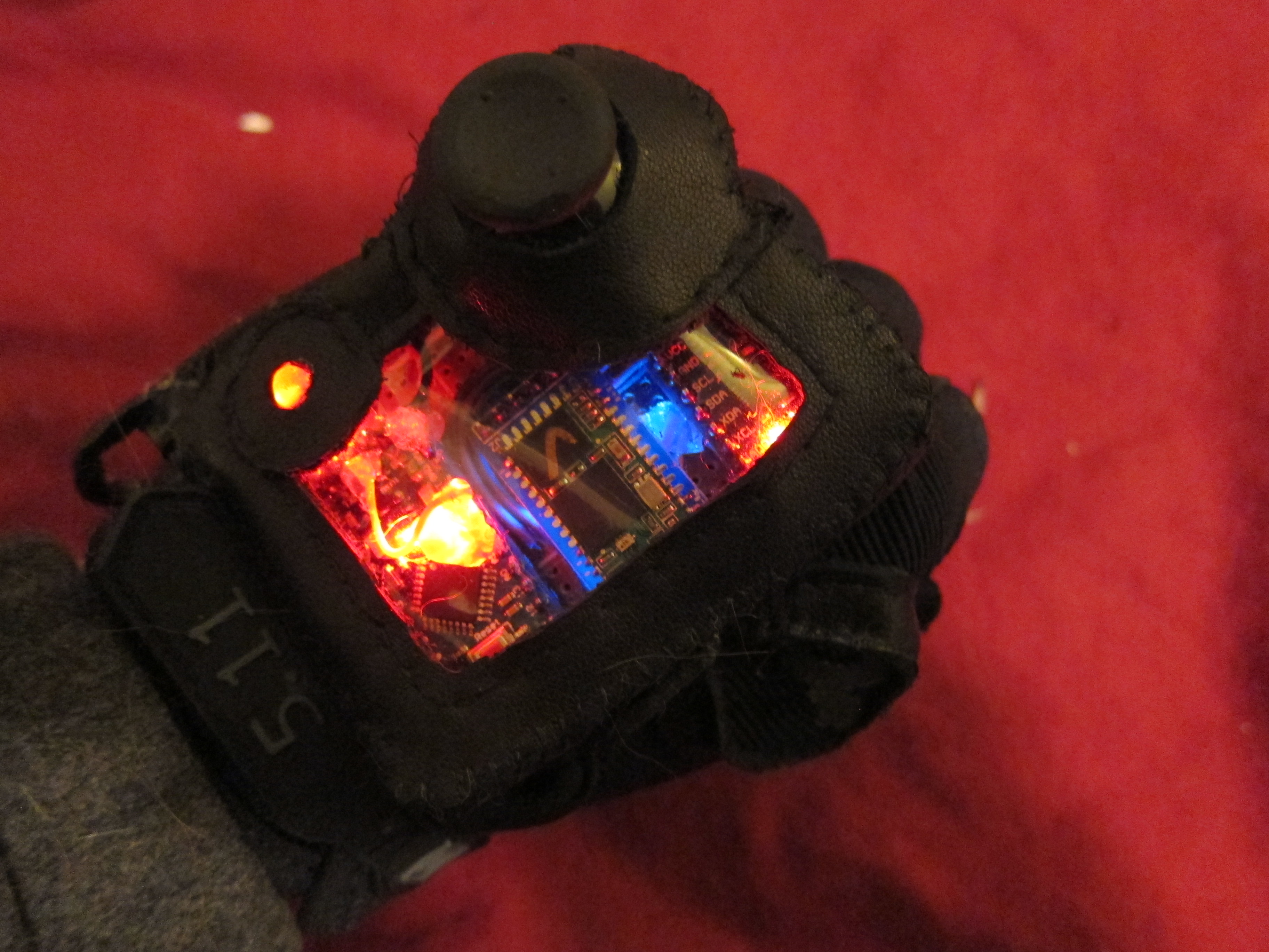
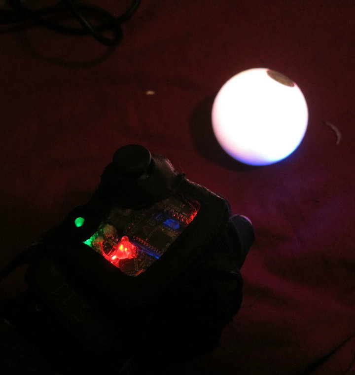
Go be a cyborg.