SpaceBall 4000 Serial to USB Adapter
6097 Views, 17 Favorites, 0 Comments
SpaceBall 4000 Serial to USB Adapter
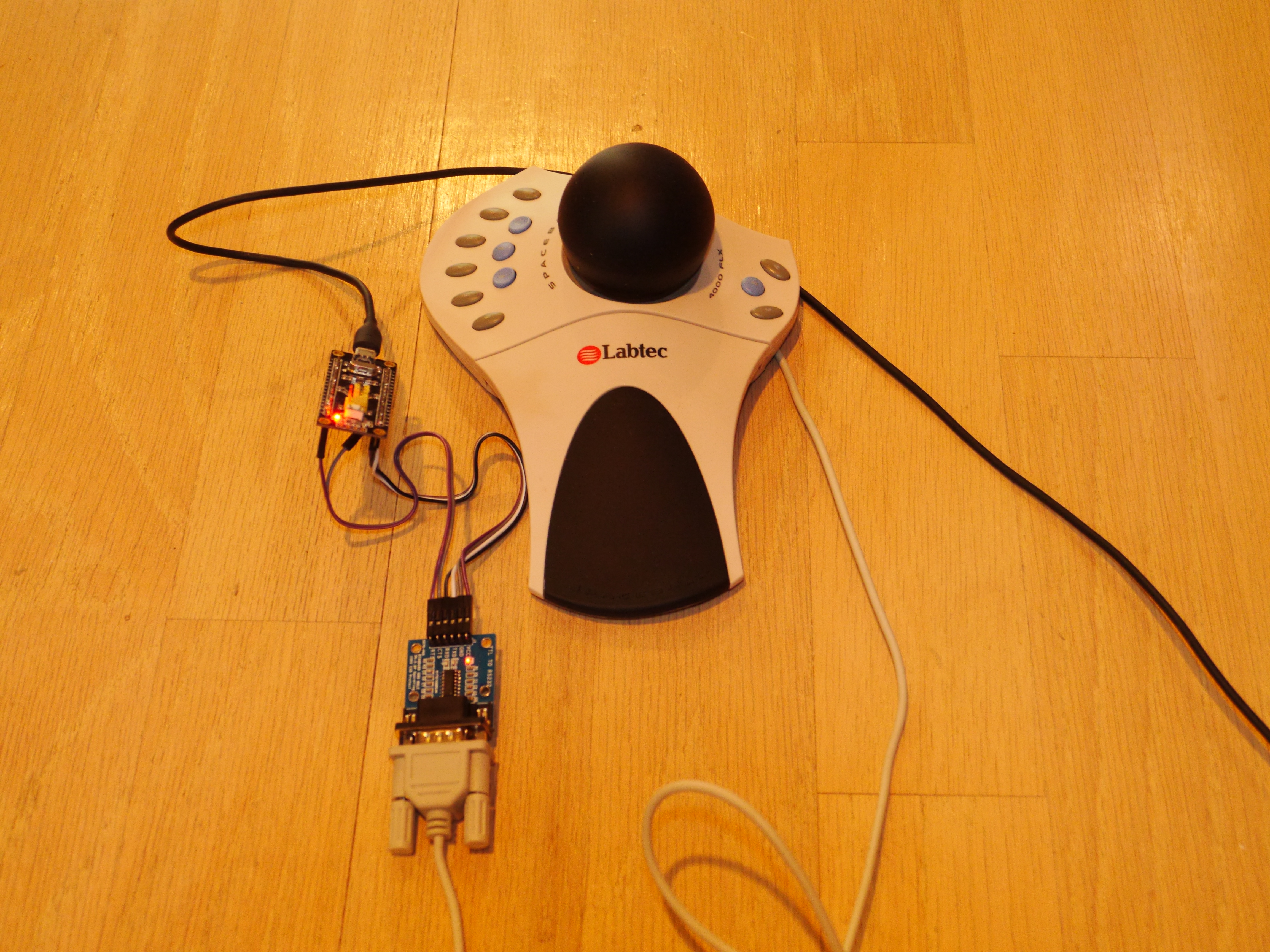
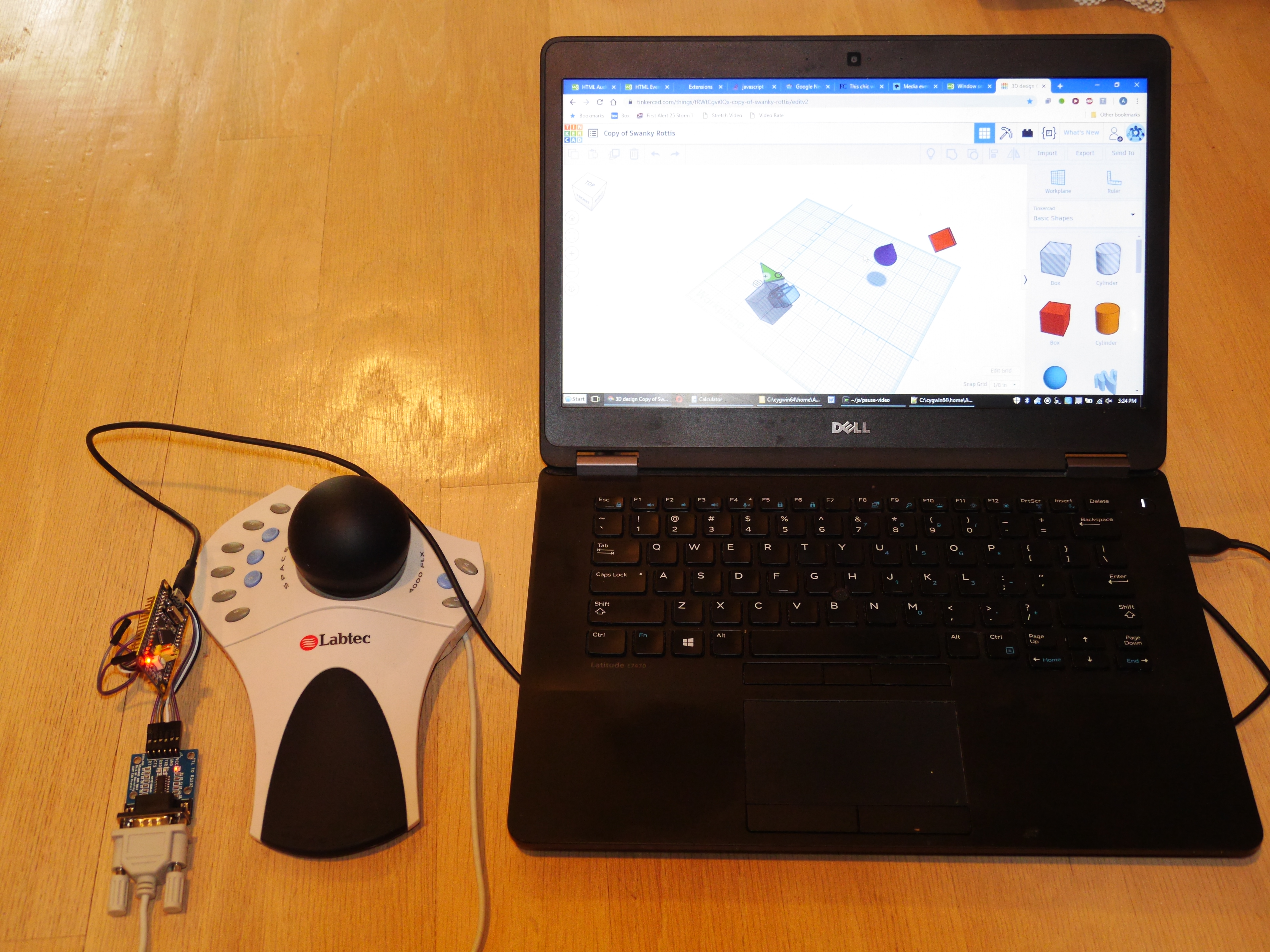
The SpaceBall 4000 (equivalent to the 5000FLX, but not the 5000) is a serial-based 3D mouse with 12 buttons that you can buy on ebay for under $20. These are nice for doing 3D graphics design, as you can move models along three axes and rotate them just by moving a ball. I recently made a Chrome extension that lets you use it in TinkerCAD, for instance. Or you can use it as a six-axis 12-button joystick (the adapter has a switchable mode that lets you activate that mode) in games like Descent.
I will show how for $5 you can build a USB adapter for the SpaceBall that makes it emulate most of the functionality of a much newer SpaceMouse Pro, so you can use it with the latest 3DConnexion drivers.
Parts for project:
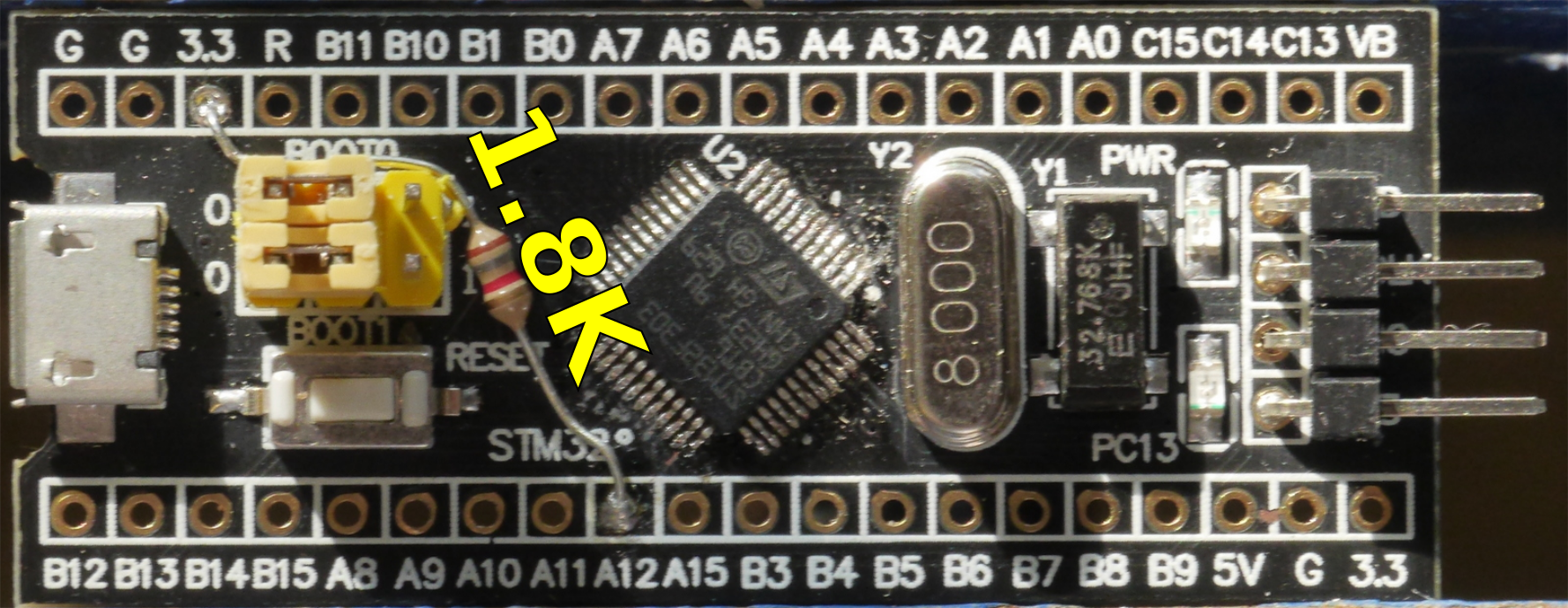
- STM32F103C8T6 minimum development board: either a black pill like this one ($1.90 shipped) or a blue pill like this one ($1.94 shipped); if you use the blue pill, you will probably need to solder an extra resistor (probably 1.8K); if you use the black pill, there is a potential (but it didn't happen when I tried it with the SP3232 board) that you will have some power supply problems and will need to solder a wire directly to a diode on the board.
- An SP3232 TTL to RS232 DB9 male board like this one (ebay $3.09).
Tools:
- USB to UART adapter for loading the bootloader on the development board. If you have one sitting around, you can use an Arduino for this, or one of the many USB to UART adapters on aliexpress for around $1
- soldering iron
- computer for running the Arduino IDE.
Load Bootloader and Prepare Arduino Environment
Follows steps 1 and 2 in this Instructable to load the bootloader on the board and prepare the Arduino IDE for the board (you can skip the GameControllers library, though).
If you have a blue pill, measure the resistance between PA12 and 3.3V. If it's significantly more than 1.5K, put a resistor between these two pins to parallel the existing resistance and bring it down to 1.5K. If you measured 10K, you should put a 1.8K resistor in. (Note that some boards that have the blue pill layout are black in color. The way to tell them apart is that the blue pill layout includes a 5V line.)
Connect Serial Board
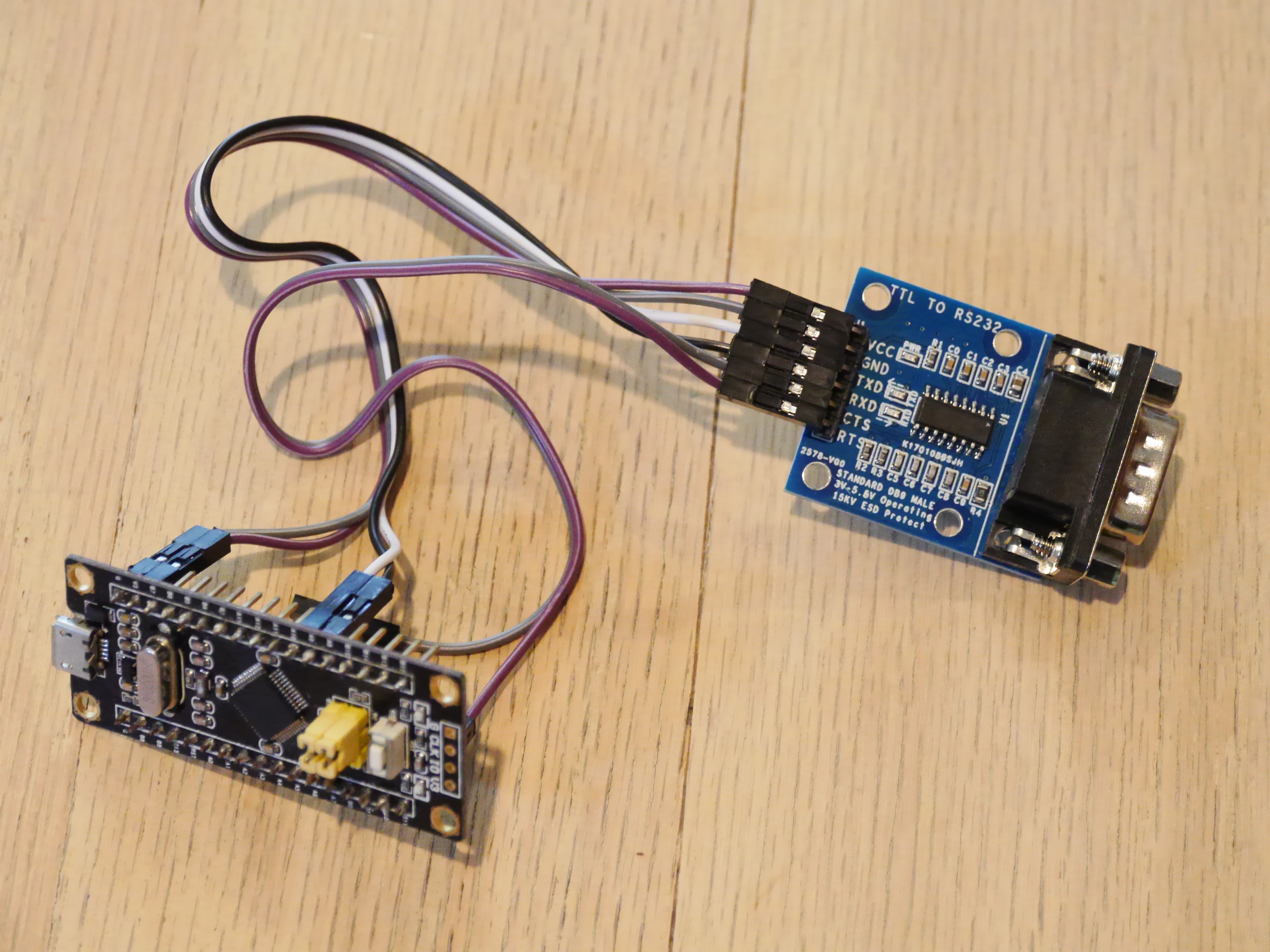
Make the following connections between the RS232 adapter and the pill:
- VCC - V3
- GND - G
- TXD - A10
- RXD - A9
- RTS - B11
Connect the SpaceBall to the RS232 adapter. Plug the pill into a USB port. Wait a few seconds. If all goes well, the SpaceBall will emit two beeps. This shows that the electrical connections are good. If you have trouble, see the "What to do if it's underpowered?" step.
Load the Sketch Onto the Board
Load my Mouse3D sketch into Arduino. If you have a Blue Pill, edit the LED line to be PC13 instead of the Black Pill's PB12.
Plug the pill into your computer.
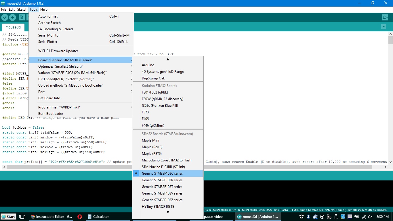
Go to Tools | Board and scroll down to select Generic STM32F103C series.
Press the Upload (right arrow) button in the Arduino IDE.
That's all. You now have an adapter. Unplug it and plug it back in to use it. I recommend you download the latest 3D Connexion drivers for it. Your adapter makes the device pretend to be a SpaceMouse Pro, except that it's missing the last three of the SpaceMouse Pro's buttons.
You can also run the SpaceBall as a generic USB joystick (calibrate with Win-R joy.cpl on Windows). To switch to USB joystick mode, press the 4, 5, 6 and 2 buttons at the same time. To switch back to SpaceMouse Pro, either reset the adapter (unplug and re-plug, or press the reset button on it) or press the 4, 5, 6 and 1 buttons.
What to Do If It's Underpowered?
If you're unlucky, you may find that the SpaceBall 4000 is underpowered and either doesn't beep initially. Another symptom is sending button presses (you can view them with joy.cpl on Windows) but not ball movement.
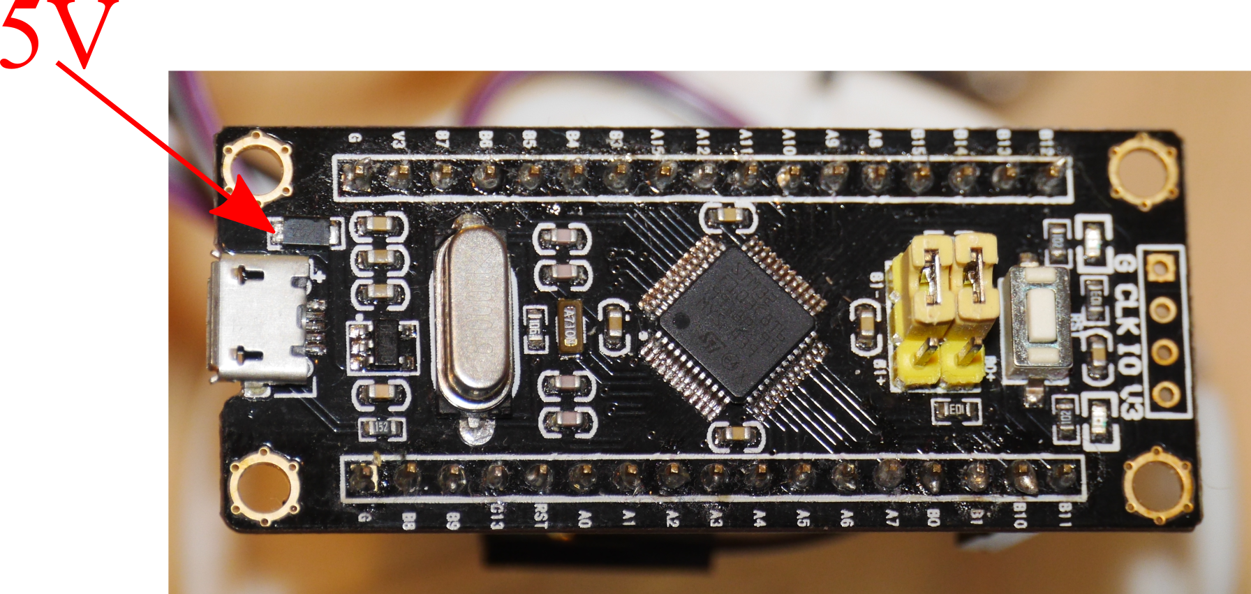
In that case, you want to change the power supply to the UART-to-RS232 converter board from 3.3V to 5V. If your STM32 board has a 5V pin (blue pills have it), that's easy: just connect that to the converter board's VCC instead of 3.3V. If the board doesn't have a 5V pin (black pills don't have it), you'll need to solder the power line to the diode on the board.