Space Shuttle : Printing and Assembly Guide
by Kmobrain in Workshop > 3D Printing
7776 Views, 27 Favorites, 0 Comments
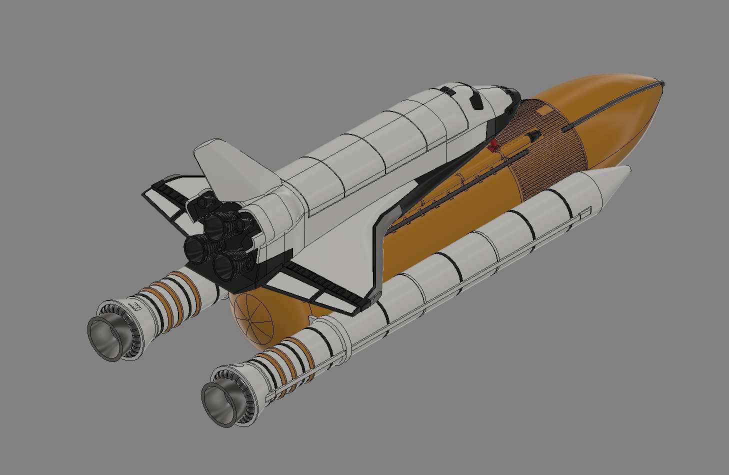
Space Shuttle : Printing and Assembly Guide
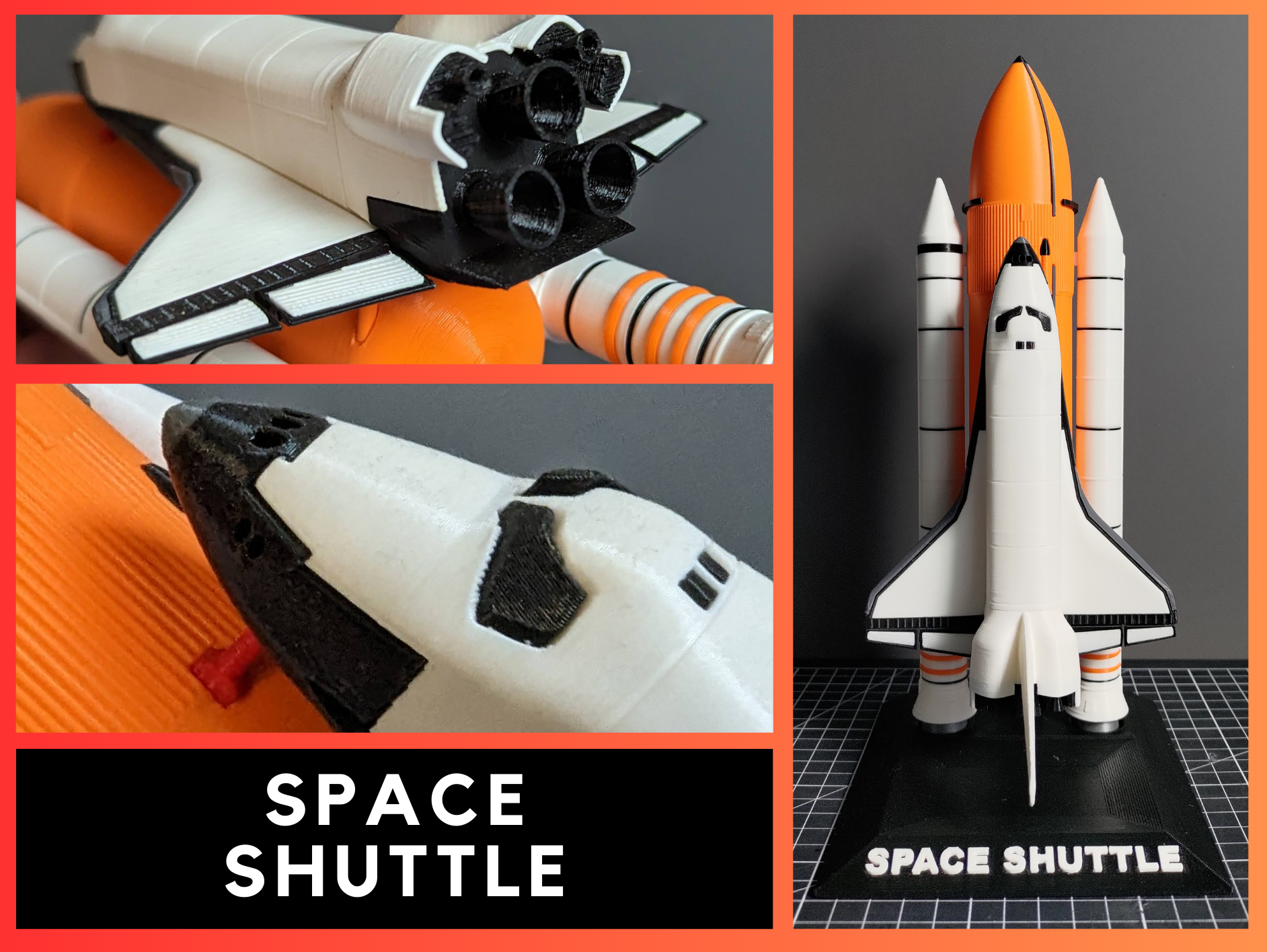
Here's a guide to printing my model of the Space Shuttle.
In this guide you will be guided through the correct positioning of the parts on the board, the settings in the Slicer and the assembly of the model.
Supplies
Here's the material used in this guide.
- 3D Printer
- 3D Slicer
- 3D files of my Space Shuttle model available on Printables.
- Black Filament
- Grey Filament
- Orange Filament
- White Filament
- Red Filament
- Glue
Choix De Configuration
Before continuing, you'll need to choose the configuration of your Space Shuttle.
Choosing your Solid Rocket Booster (SRB)
- The Cut-Booster Kit (CB)
- 🔼For small printers, pieces with a maximum height of 13cm.
- 🔼Easy to print
- 🔽Many parts to print.
- 🔽Lower final rendering with top and bottom parts joined.
- The Full-Booster Kit (FB)
- 🔽For large printers, parts with a maximum height of 22cm.
- 🔼Fewer parts to print.
- 🔼Easy to print
- 🔼Very good final rendering without joins for top and bottom parts.
Choosing your Fuselage
- Cut Fuselage Kit (CF)
- 🔼For small printers, pieces with a maximum height of 13cm.
- 🔼Easy to print
- 🔽Large quantity of parts
- 🔽Less good finish
- Fuselage kit (F)
- 🔼For small printers, parts with maximum height of 13cm.
- 🔼Good finish
- 🔼Medium number of parts
- 🔽Medium printing difficulty
- Kit Full Fuselage (FF)
- 🔼For small printers, parts with a maximum height of 16cm.
- 🔼Excellent finish
- 🔼Small quantity of parts
- 🔽Major printing difficulties
The Slice
PRINCIPLE OF THE TABLE
I've divided the slice steps into 'blocks' corresponding to the stages of the rocket, but you can do the slice in any order you like.
In each slice step you'll find a table with my advice on a number of parameters.
- The Supports will be in green in the slicer images, and I'll also put a note in the image.
- The Rafts, Brim and HelpDisk will be selected according to your usual settings in case your parts come unstuck.
- The Top Fill pattern is for a prettier result, but you can choose whatever you like.
- Temperature and Speed can be modified for certain parts, but your usual settings may also be valid.
- Thin walls can be activated on certain parts, but as with temperature and speed, your usual settings may also be valid.
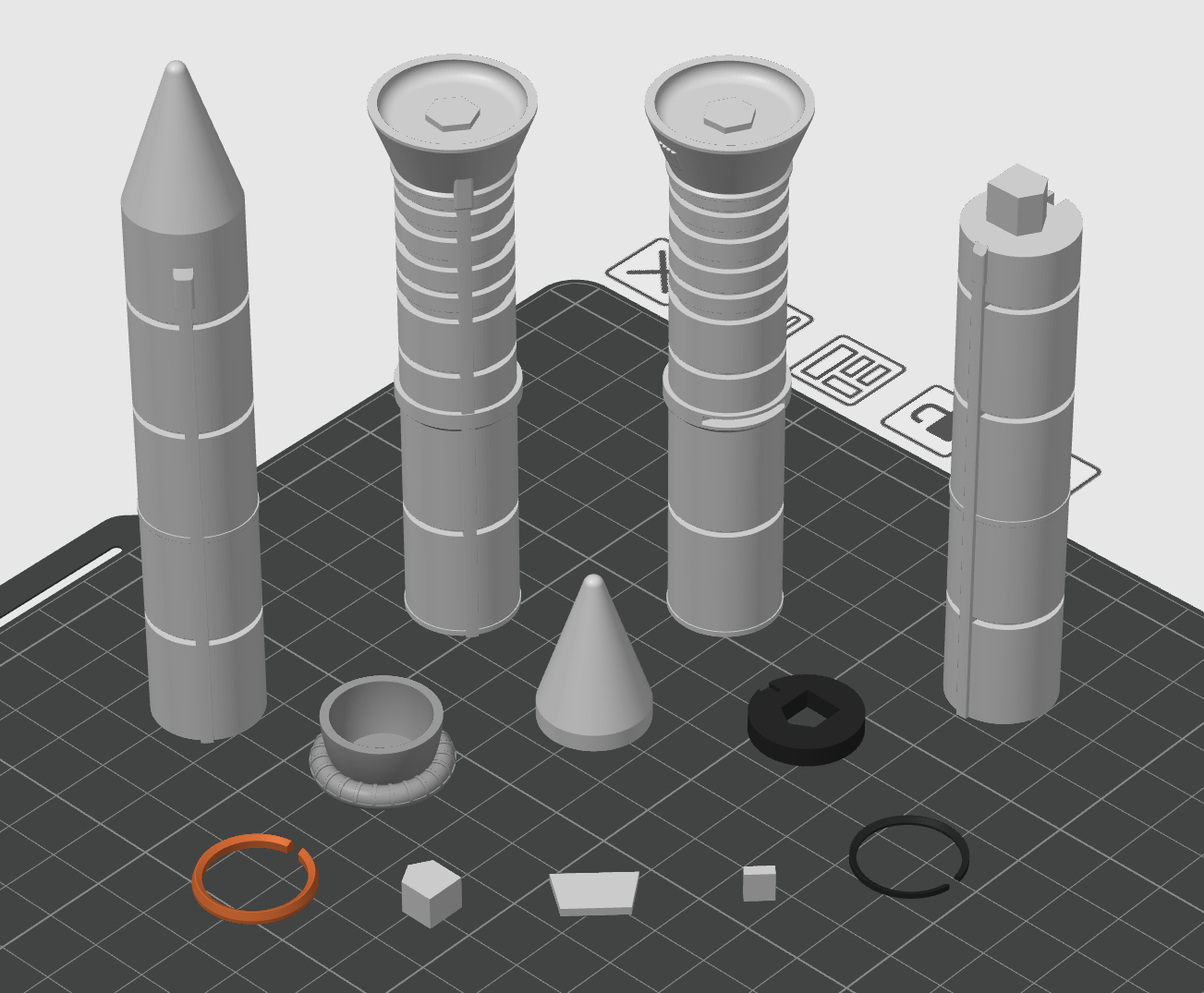
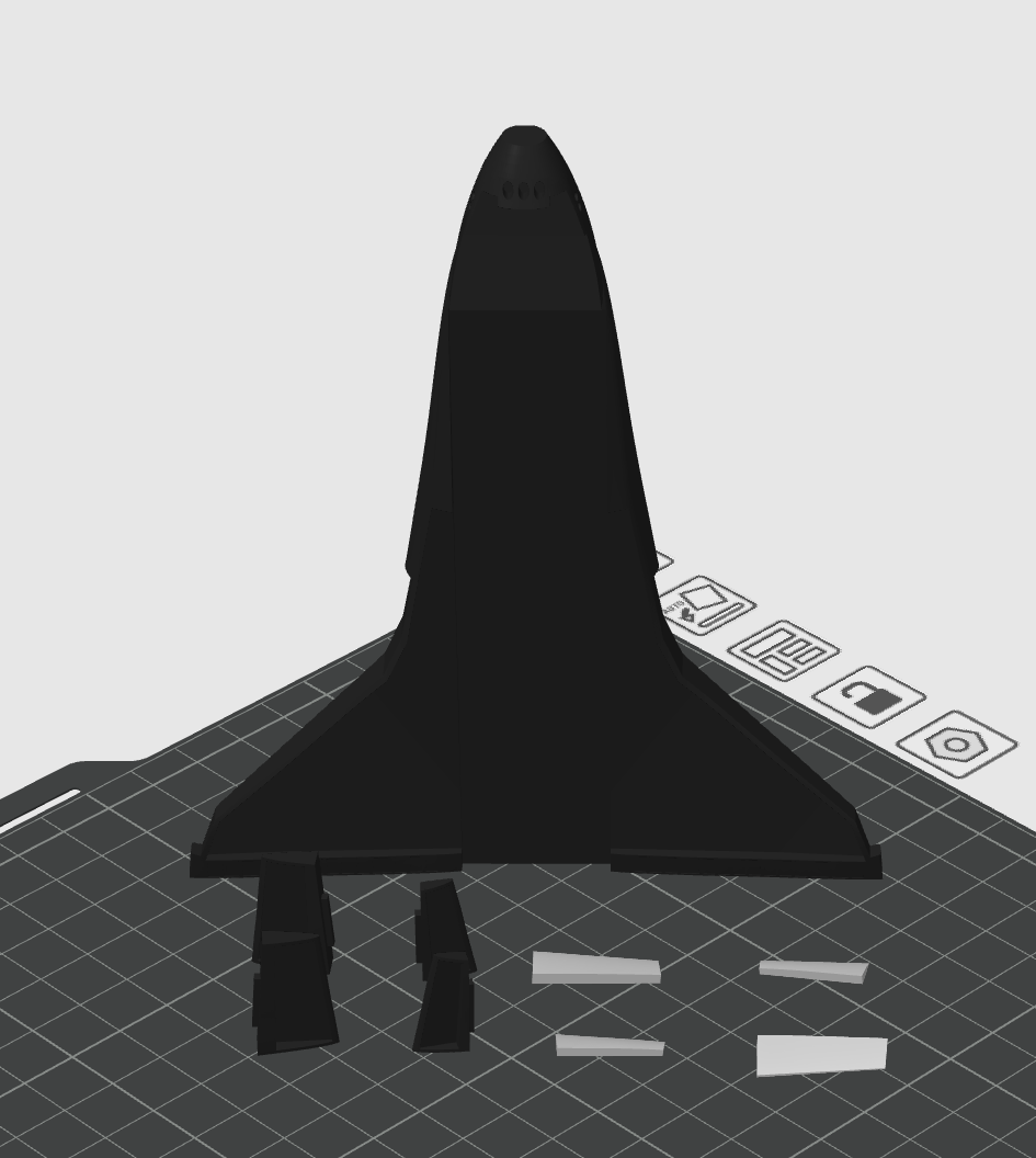
There's also a picture for the ideal placement of each piece. I only placed one piece of each, but it can be repeated for the quantity requested.
I also added annotations to some of the images.
IMPORTANT
For "Jonction" parts, I advise you to print as tightly as possible, adding 1% by 1% to the scale to ensure perfect assembly.
Slice External Tank (ET)
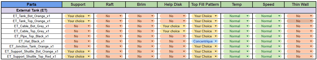
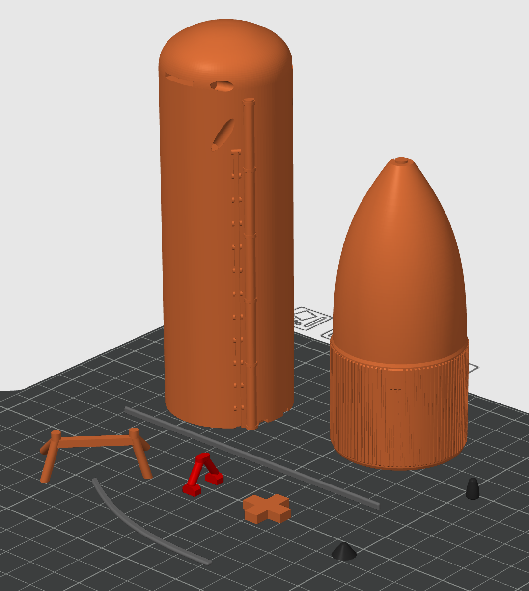
There are no specific settings for the External Tank block.
The supports are not required for the parts but can help in the case of printing problems.
You can put "Help Disks" on the "ET_Cable_Grey" if you can't print them without them.
Slice Kit Cut-Booster (CB) for SRB
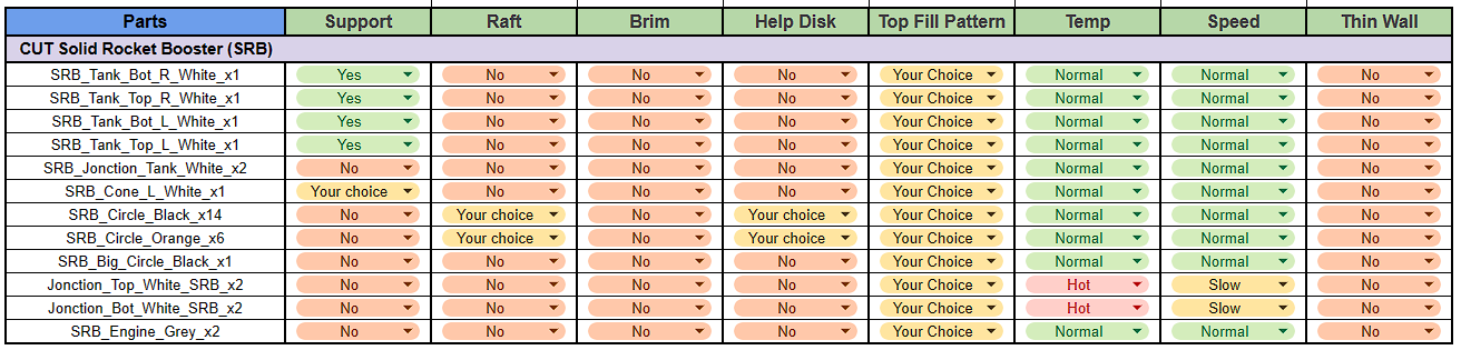
Slice for the Cut-Booster Kit
if you have chosen the Full-Booster Kit go to the next step.
For Solid Rocket Booster there are specific settings for speed and temperature only for "SRB_Jonction_Top/Bot" but you can try with normal settings first.
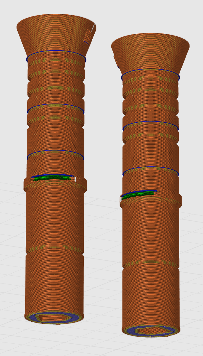
Same as last step for supports are required for "SRB_Tank" they are in green on the slicer pictures.
A "Raft" or "Help Disk" on the "SRB_Circle" if you can't print them without one.
Slice Kit Full-Booster (FB) for SRB
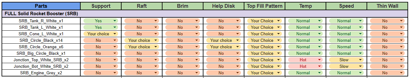
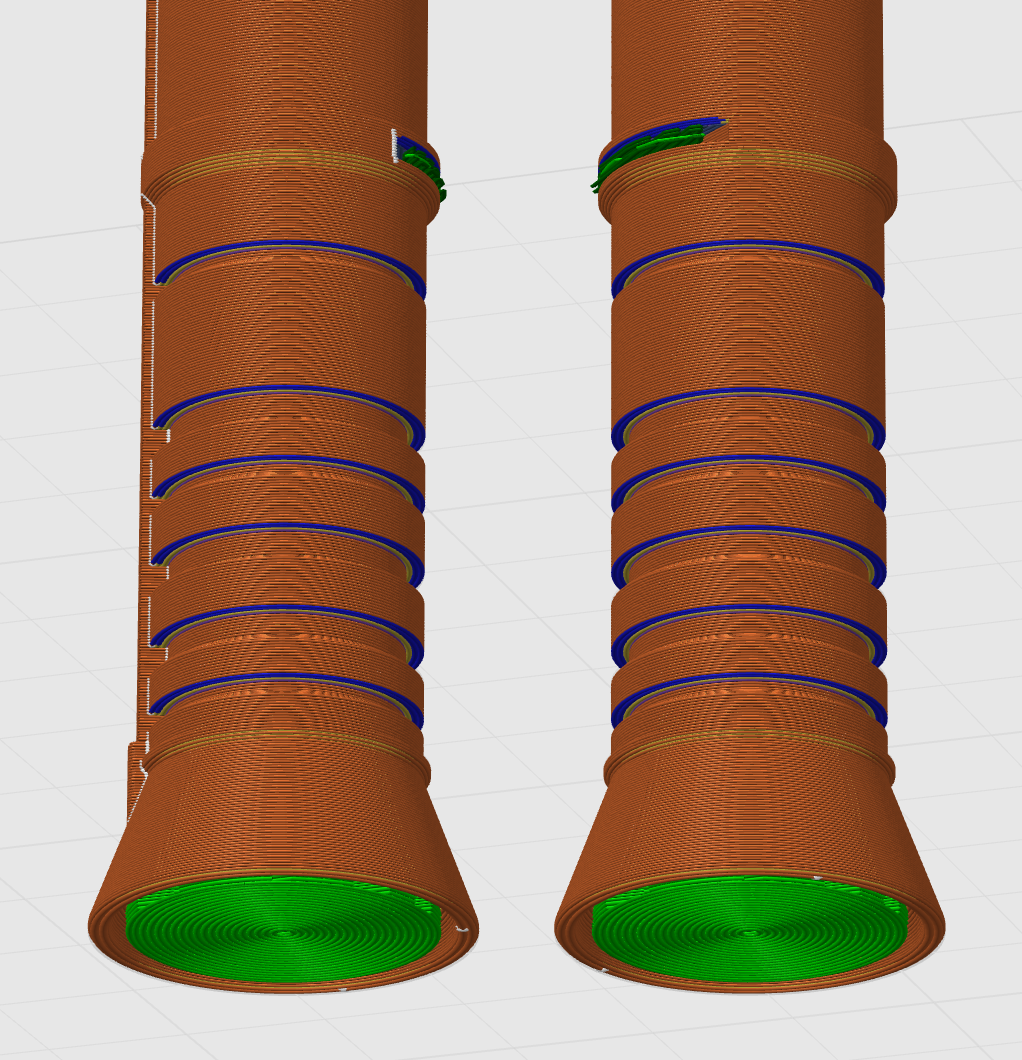
Slice for the Full-Booster Kit.
For Solid Rocket Booster there are specific settings for speed and temperature only for "SRB_Jonction_Top/Bot" but you can try with normal settings first.
Same as last step for supports are required for "SRB_Tank" they are in green on the slicer pictures.
A "Raft" or "Help Disk" on the "SRB_Circle" if you can't print them without one.
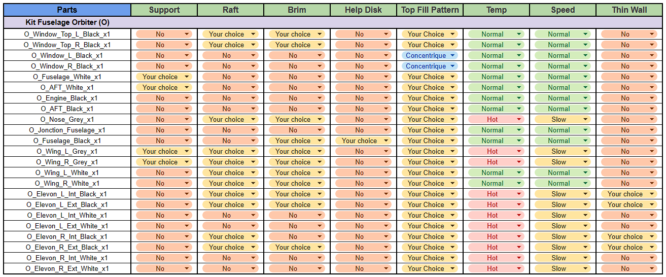
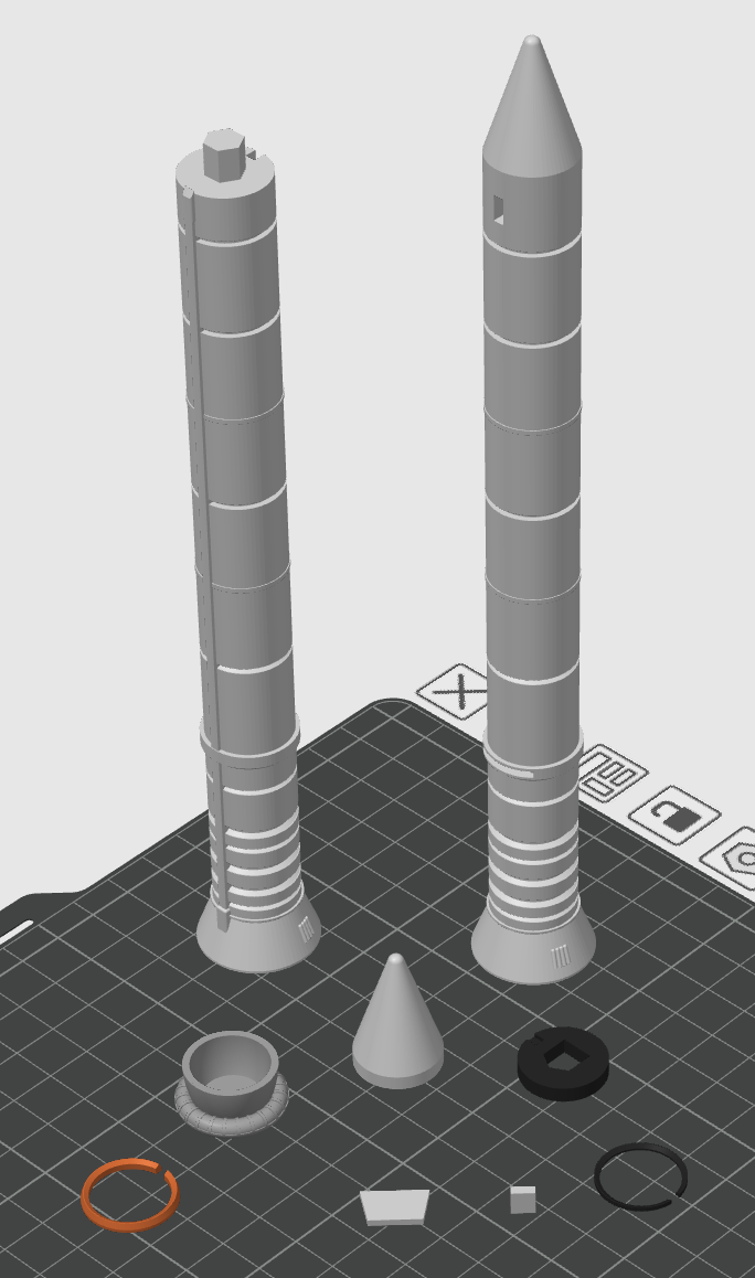
Slice Orbiter (O)
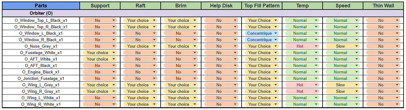
For the Orbiter there are specific speed and temperature settings only for the "O_Nose_Grey" and "O_Wing_L/R_Grey", but you can try the normal settings first.
Supports are not required for any part but can help for "O_AFT_White" and "O_Wing_L/R_Grey" as shown in green in the image above.
Raft and Brim can help in case of poor grip on small parts like "Windows" or "Wing".
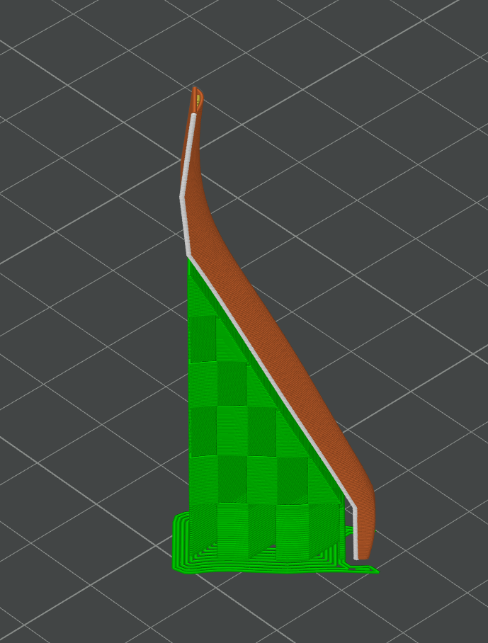
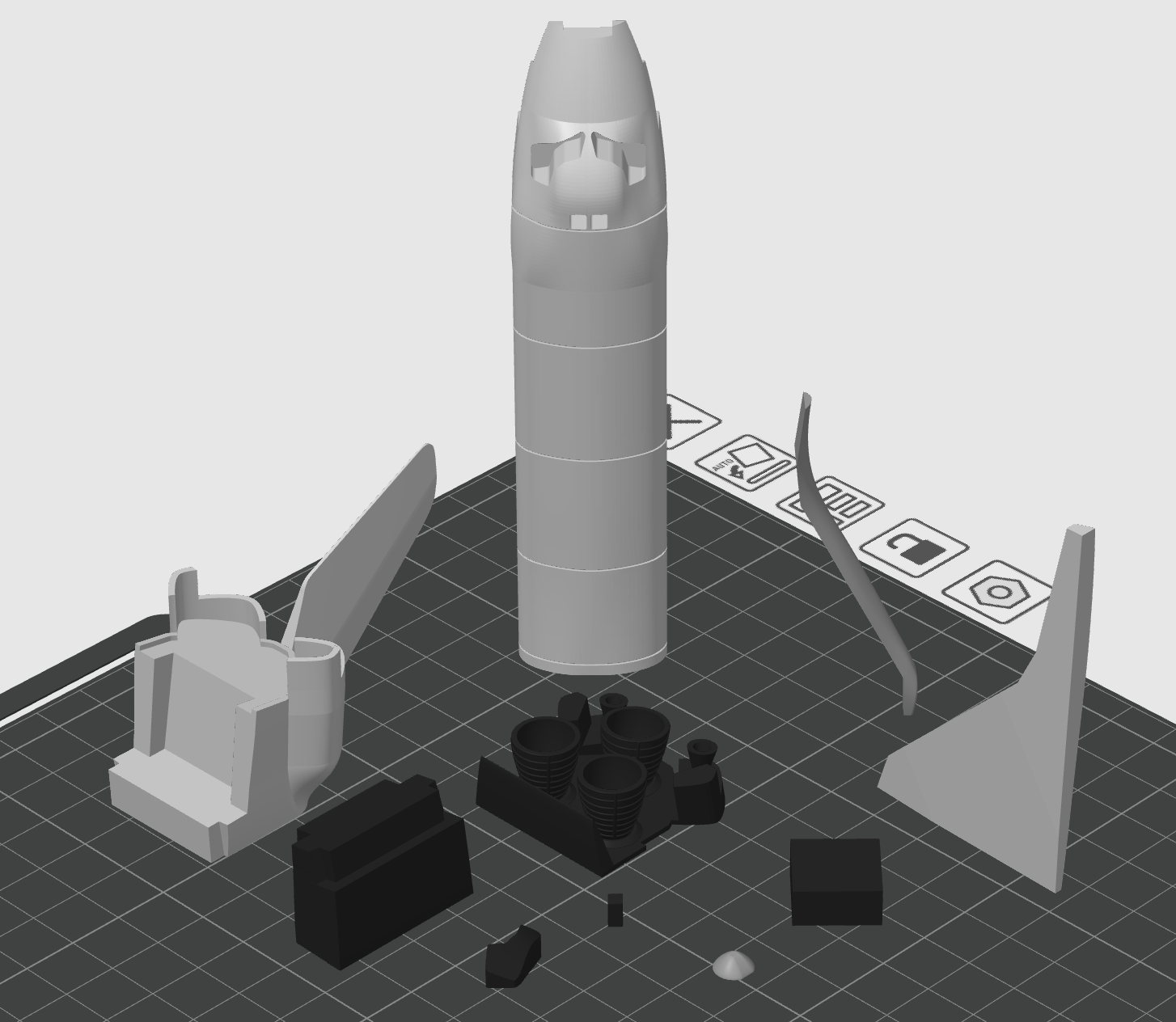
Slice Kit Cut-Fuselage for Orbiter
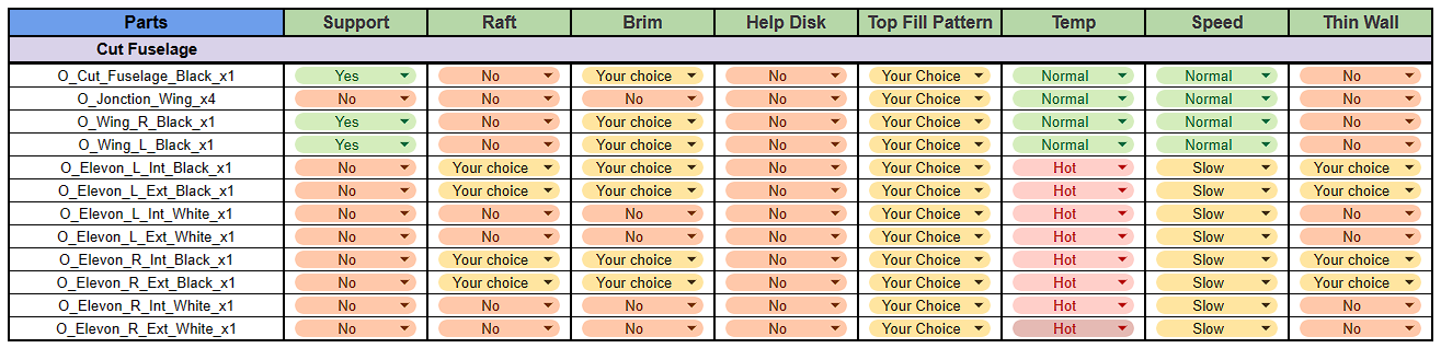
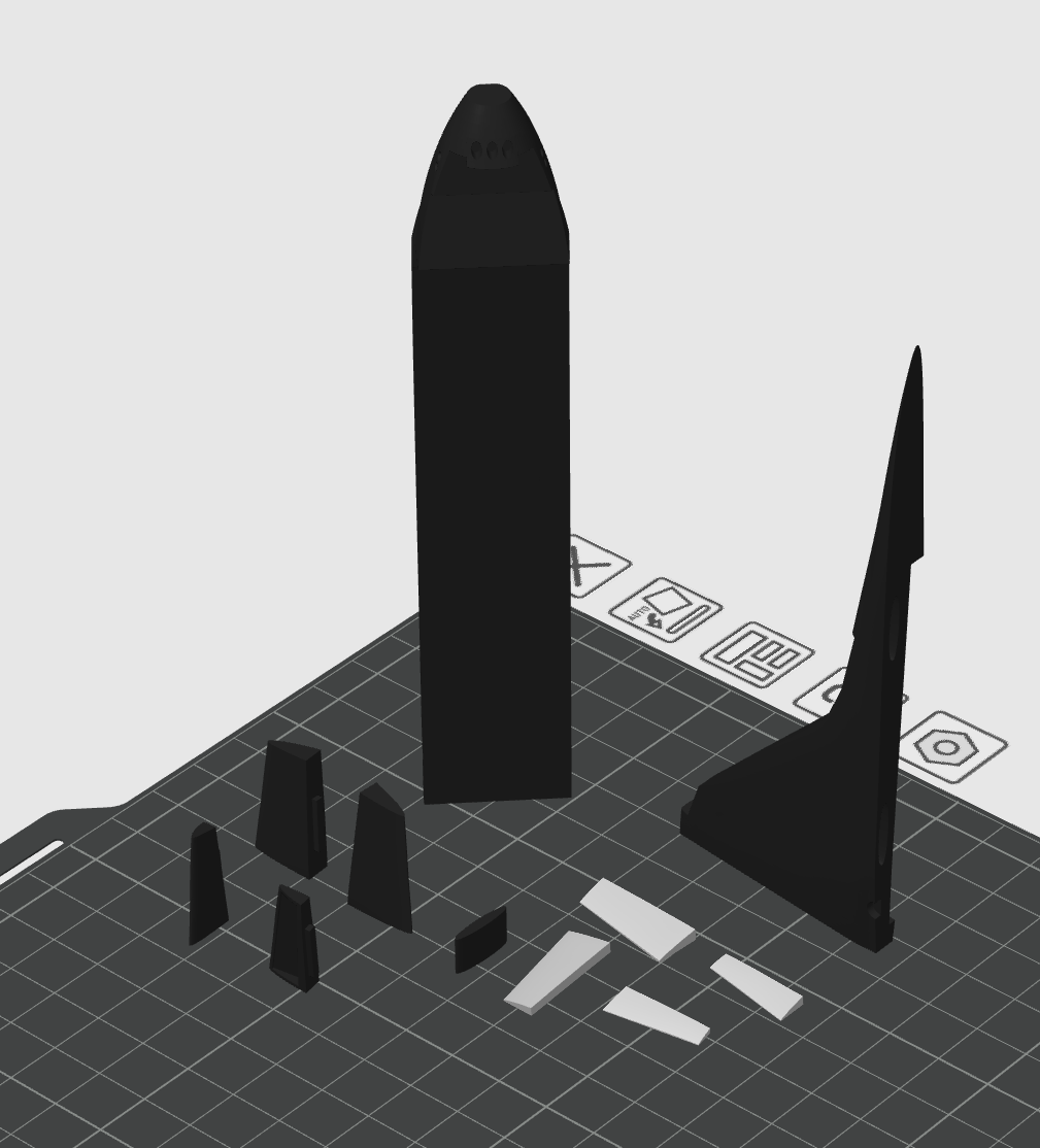
Slice for the Cut-Fuselage Kit.
There are specific speed and temperature settings for the "O_Elevon", but you can try the normal settings first.
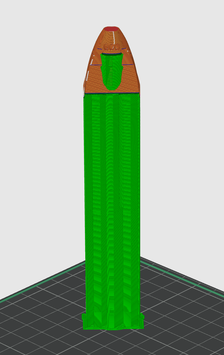
Supports are required for some parts, as shown in green in the image above.
You can use "Raft" or "Brim" for "O_Elevon_Black".
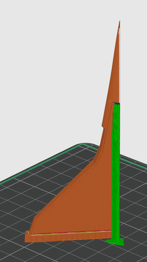
Slice Kit Fuselage for Orbiter
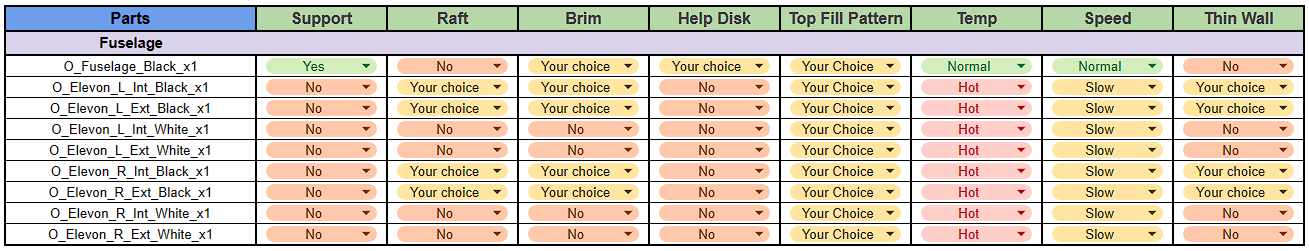
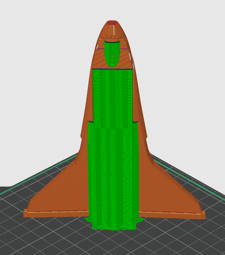
Slice for the Fuselage Kit.
There are specific speed and temperature settings for the "O_Elevon", but you can try the normal settings first.
Supports are required for the "O_Fuselage" as shown in green in the image above.
You can use "Raft" or "Brim" for "O_Elevon_Black".
Slice Kit Full-Fuselage for Orbiter
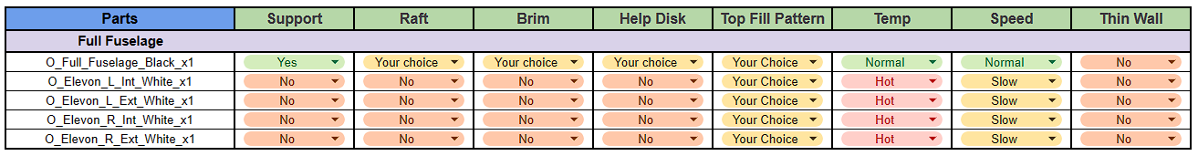
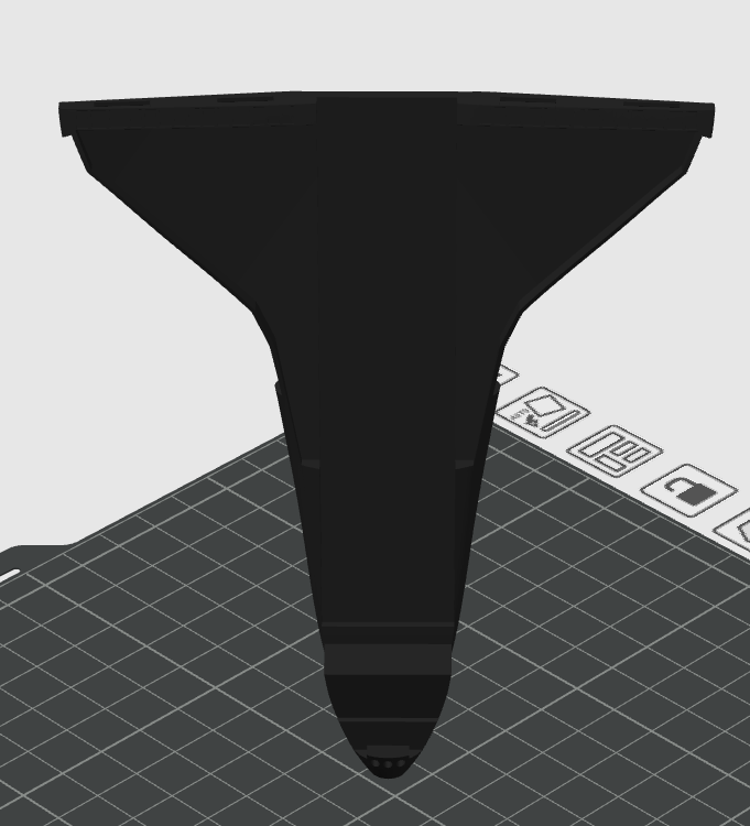
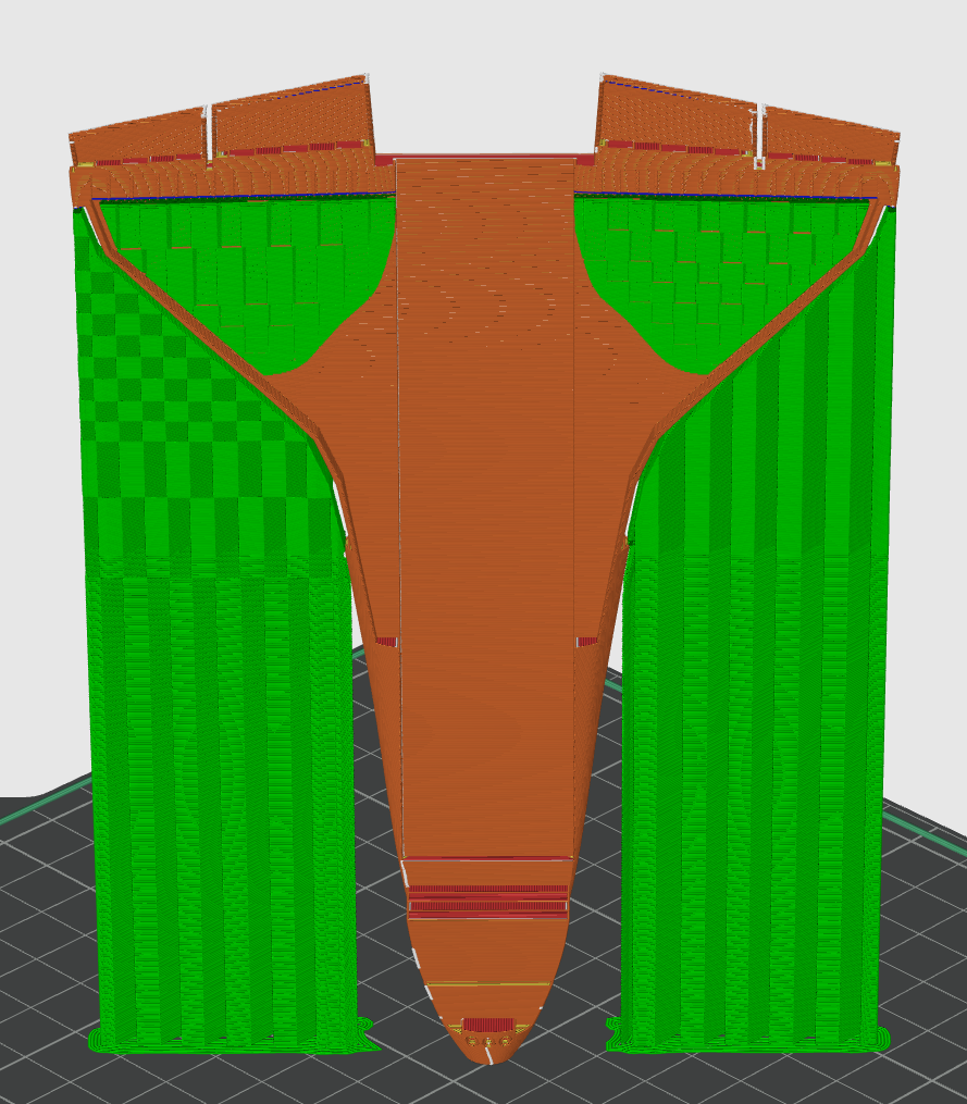
Slice for the Full-Fuselage Kit.
There are specific speed and temperature settings for the "O_Elevon", but you can try the normal settings first.
Supports are required for the "O_Full_Fuselage" as shown in green in the image above.
Slice Stand

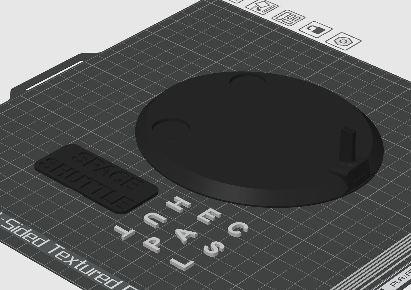

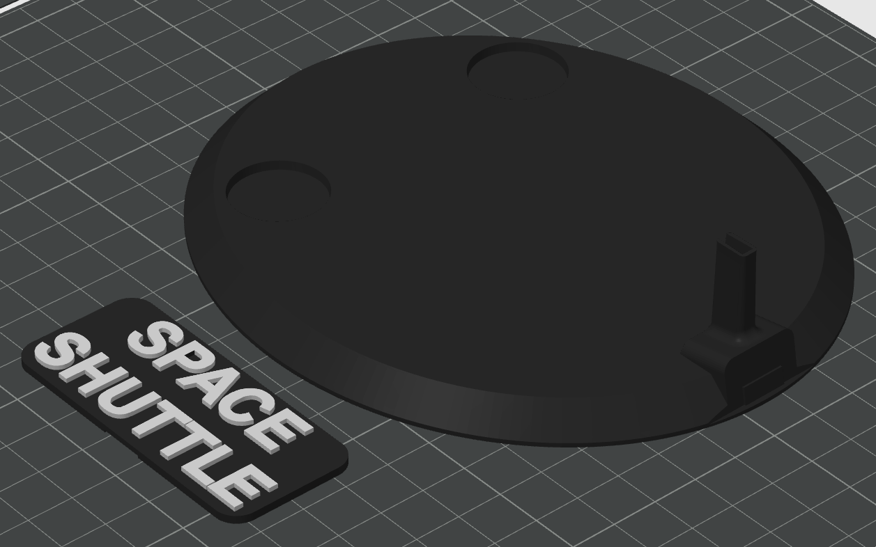
Slice for the Cut-Stand Kit (CS).
- No specific setting, you just need a "Raft" for the "Letters_White" if you can't print on the bed alone.
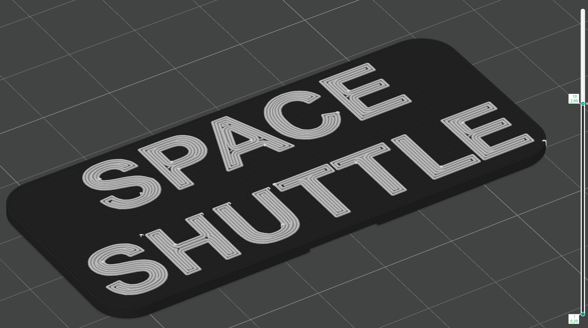
Slice for Full-Stand Kit (FS).
- For the "Full_Name" :
- If you have a multi-material printer, simply set the letters to white.
- If you don't have a multi-material printer, you'll need to make a layer 10 color change (see image above).
Assembly
The assembly steps will also be divided by Block, this time I advise you to follow the direction of the guide.
At the bottom right of each image there will be a step code, the letter for the Block and the number for the step, for example ET1 for step 1 of Block ET.
Assembly External Tank (ET)
Once the supports have been removed, you can begin assembly.
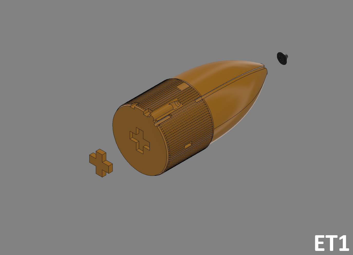
ET1
- Glue the "ET_Jonction_Tank_Orange" junction block to the bottom of the "ET_Tank_Top_Orange" tank, then glue the "ET_Cable_Top_Grey" nose to the top.
ET2
- Then glue everything onto "ET_Tank_Bot_Orange" (take care to align the "ET_Cable_Grey" inserts).
ET3
- Then glue the "ET_Cable_Grey" and "ET_Hat_Black" cables into the inserts provided.
ET4
- Last step, glue the obiter supports "ET_Support_Shuttle_Bot_Orange" and "ET_Support_Shuttle_Top_Red" in the holes provided.
Assembly Solid Rocket Booster (sRB)
Once the supports have been removed, you can begin assembly.
SRB1 (Kit Cut-SRB)
- Glue the "SRB_Jonction_Tank_White" junction blocks into the "SRB_Tank_Bot_L/R_White" bottom SRB, then glue the "SRB_Tank_Top_L/R_White" top SRB on top.
SRB Left
SRB L1
- Glue "SRB_Big_Circle_Black" on "SRB_Tank_L_White" then glue "SRB_Cone_White" on top.
SRB L2
- Then clip on the 7 "SRB_Circle_Black" and the 3 "SRB_Circle_Orange".
SRB L3
- Glue the "SRB_Engine_Grey" motor to the bottom of the "SRB_Tank_L_White".
SRB Right
SRB R1
- Then clip on the 7 "SRB_Circle_Black" and the 3 "SRB_Circle_Orange".
SRB R2
- Glue the "SRB_Engine_Grey" motor to the bottom of the "SRB_Tank_R_White".
SRB4
- Glue the "SRB_Jonction_Top_White" junction blocks to the top of both booster units, then the "SRB_Jonction_Bot_White" junction blocks to the bottom.
Assembly Orbiter (O) - Fuselage
Step only for Cut-Fuselage Kit
if you've made another choice, move on to the next step.
CF1
- Glue the "O_Jonction_Wing" connecting blocks to the "O_Cut_Fuselage_Black" main block, then glue the "O_Wing_R/L_Black" wings.
Assembly Orbiter (O)
O1
- Glue the junction block "O_Jonction_Fuselage" into the main obiter block "O_Fuselage_White", then glue the first part of the AFT block "O_AFT_White".
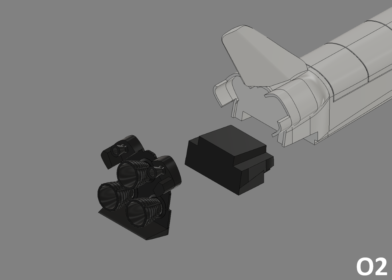
O2
- Then glue the second part of the AFT block "O_AFT_Black", followed by the engine block "O_Engine_Black".
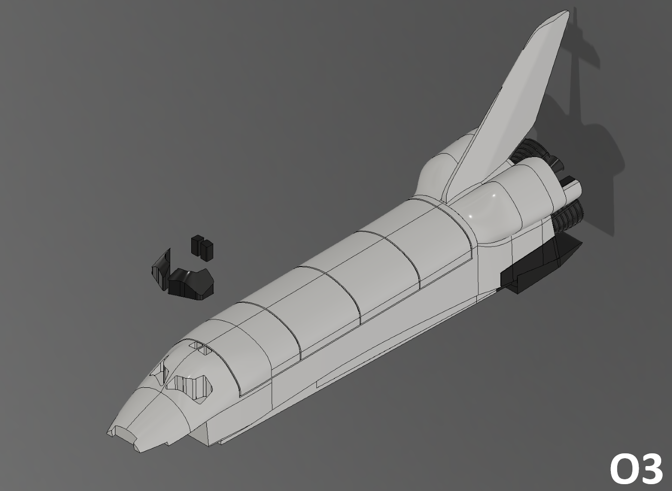
O3
- Add the main window "O_Window_L/R_Black" and the top window "O_Window_Top_L/R_Black", then lay the whole assembly to one side.
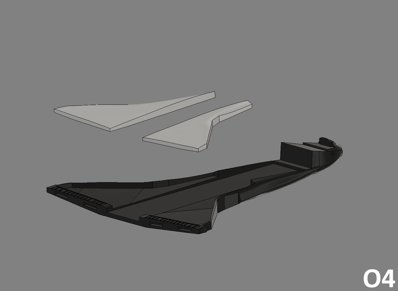
O4
- Then take the fuselage block according to your choice of kit "O_Fuselage_Black" and add the white wing parts "O_Wing_L/R_White".
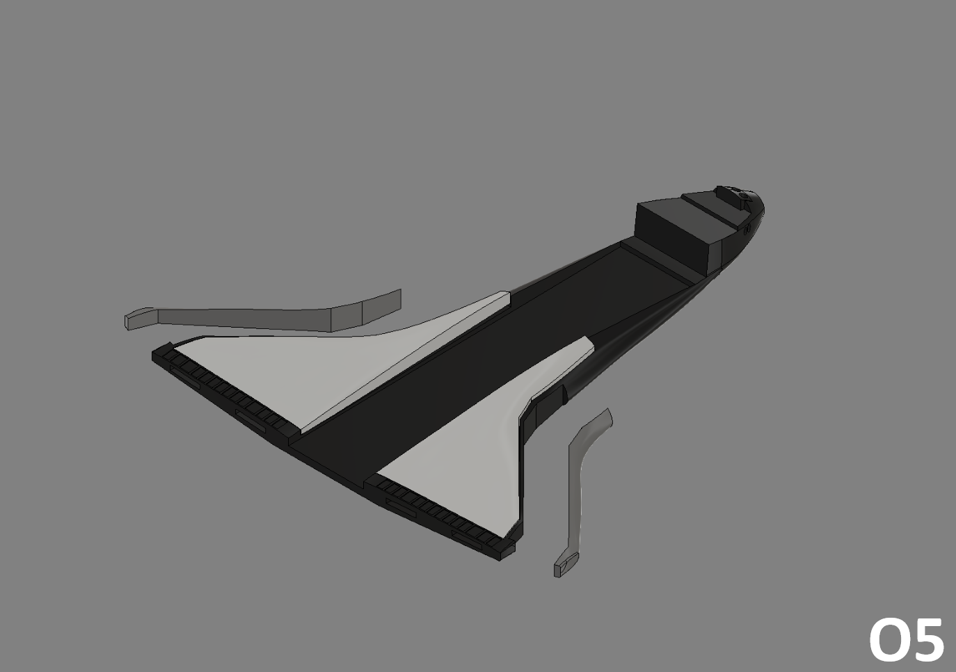
O5
- Then glue on the grey "O_Wing_L/R_Grey" wing sections.
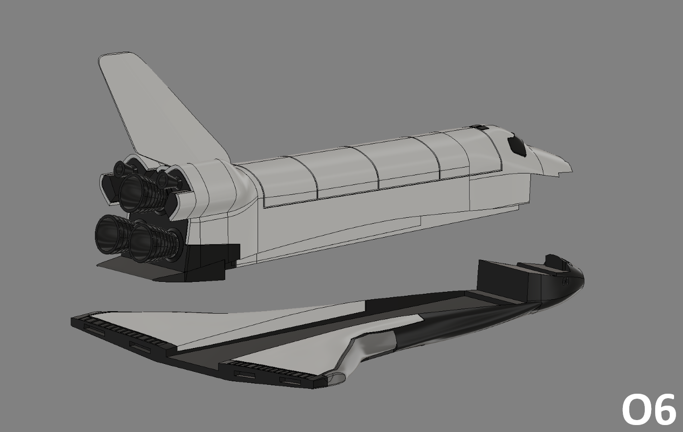
O6
- Take the first set of orbiter "O_Fuselage_White" then glue it onto the set of wings "O_Fuselage_Black".
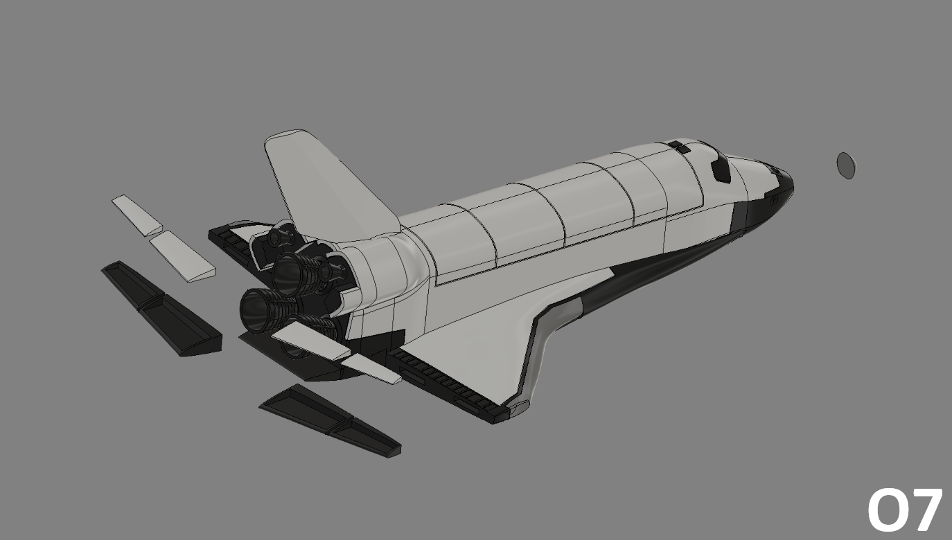
O7
- For the final step, simply add the Elevons. First glue the white parts "O_Elevon_L/R_Int/Ext_White" into the black parts "O_Elevon_L/R_Int/Ext_White".
- Then glue the elevons to the back of the fuselage wings "O_Fuselage_Black".
Assembly Stand
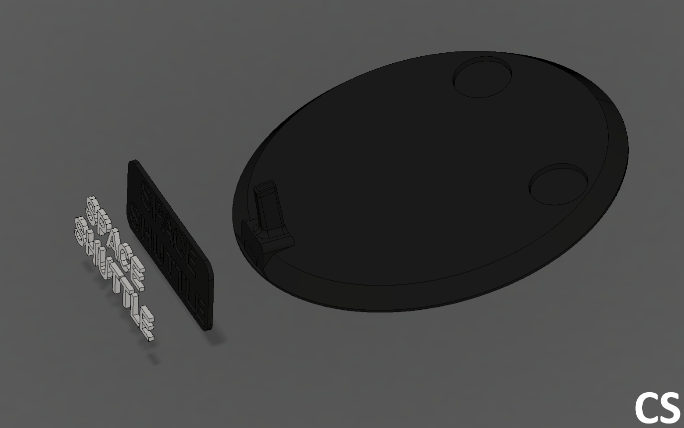
CS
- Glue the letters "S_Letters_White" in the "Stand_Name_Black" then glue the plate on the "Stand_Black".
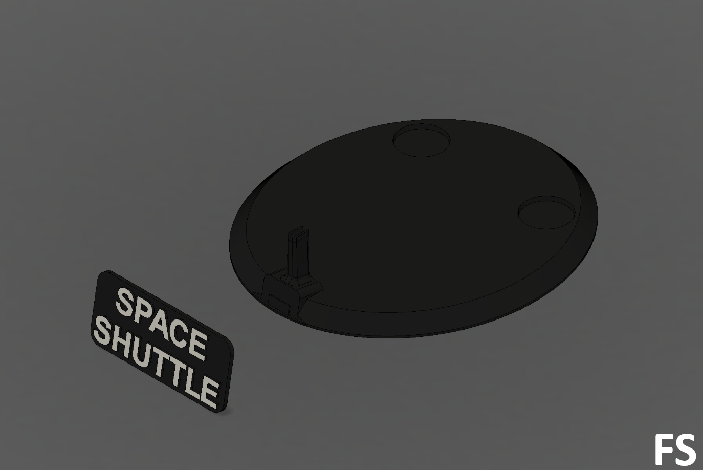
FS
- Glue the "Stand_Name" to the "Stand_Black" stand.
Final Assembly
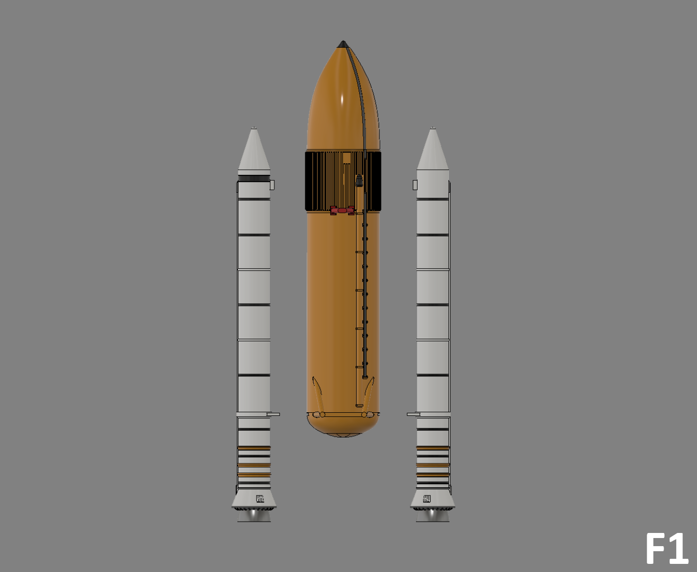
F1
- Glue the Solid Rocket Booster "SRB_Tank_L/R_White" to each side of the External Tank "ET_Tank_Orange".
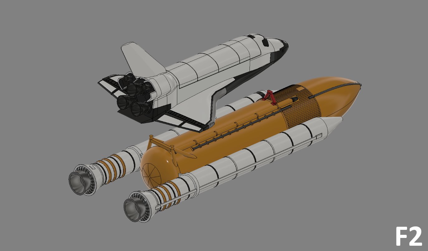
F2
- Glue the orbiter to the "ET_Support_Shuttle_Bot_Orange" and "ET_Support_Shuttle_Top_Red" brackets present on the "ET_Tank_Orange" External Tank.
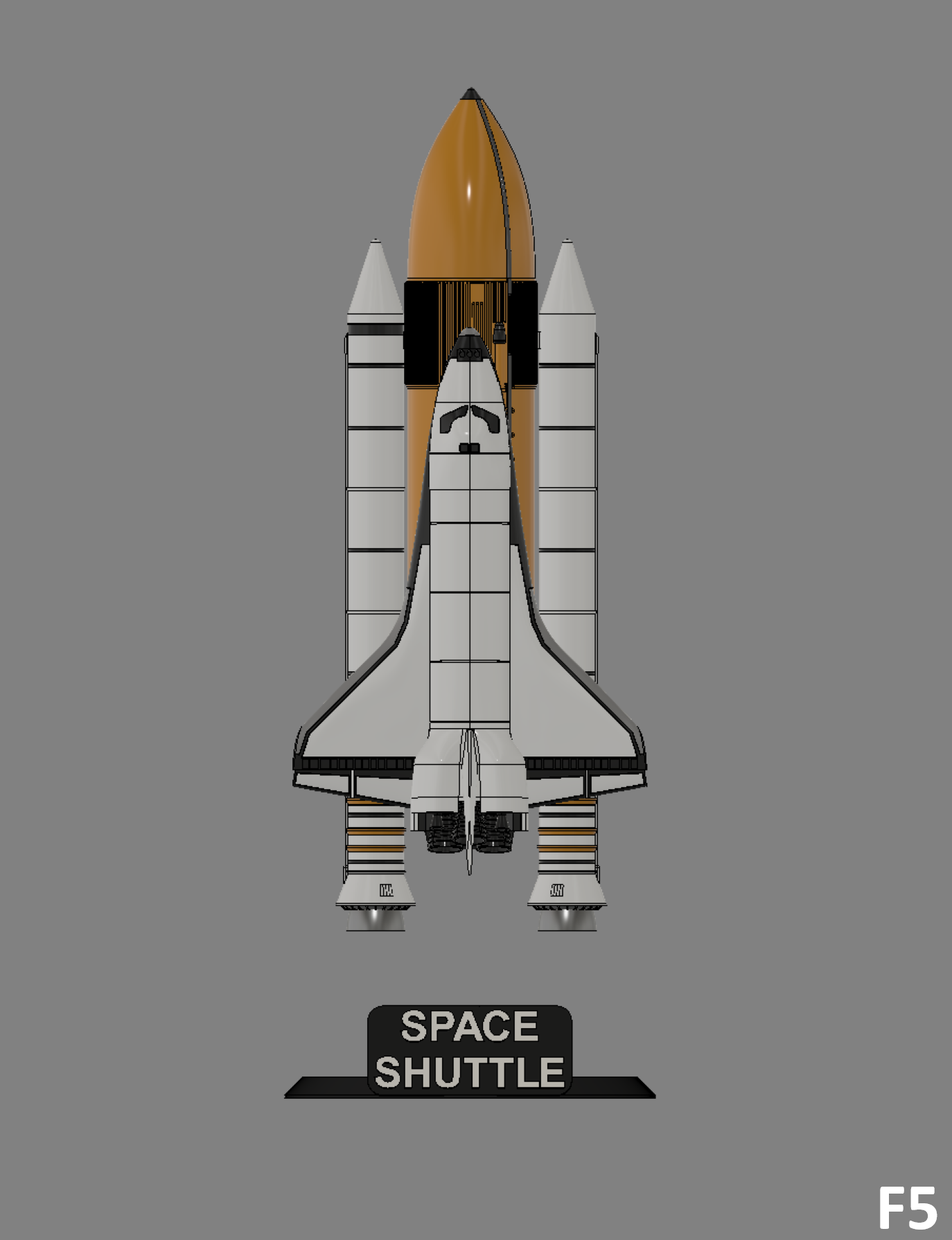
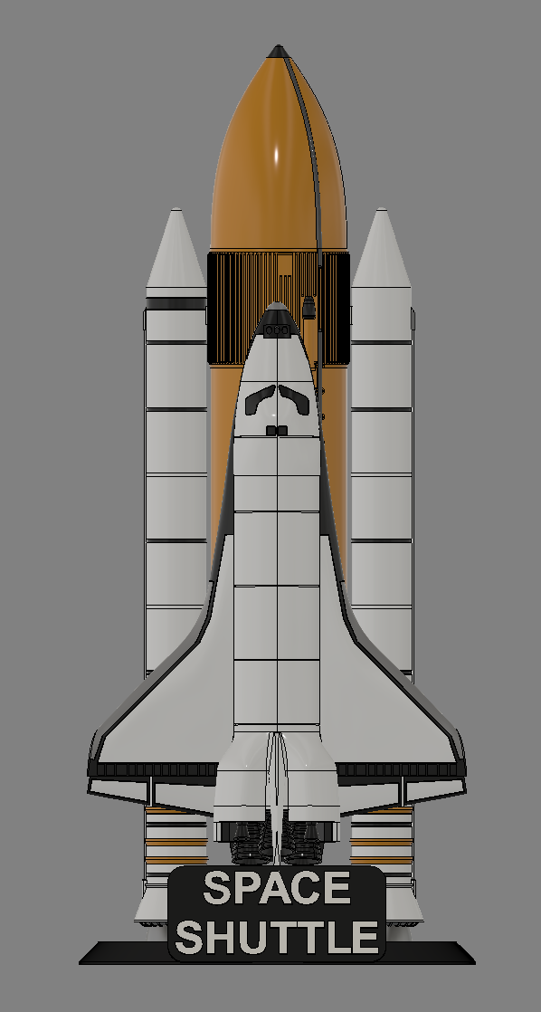
F3
- You can then put the shuttle on its "Stand_Black" stand.
Finish
Congratulations on finishing the printing and assembly of the Space Shuttle.