Animated Space Invaders Clock
by GeckoDiode in Circuits > Clocks
34611 Views, 585 Favorites, 0 Comments
Animated Space Invaders Clock
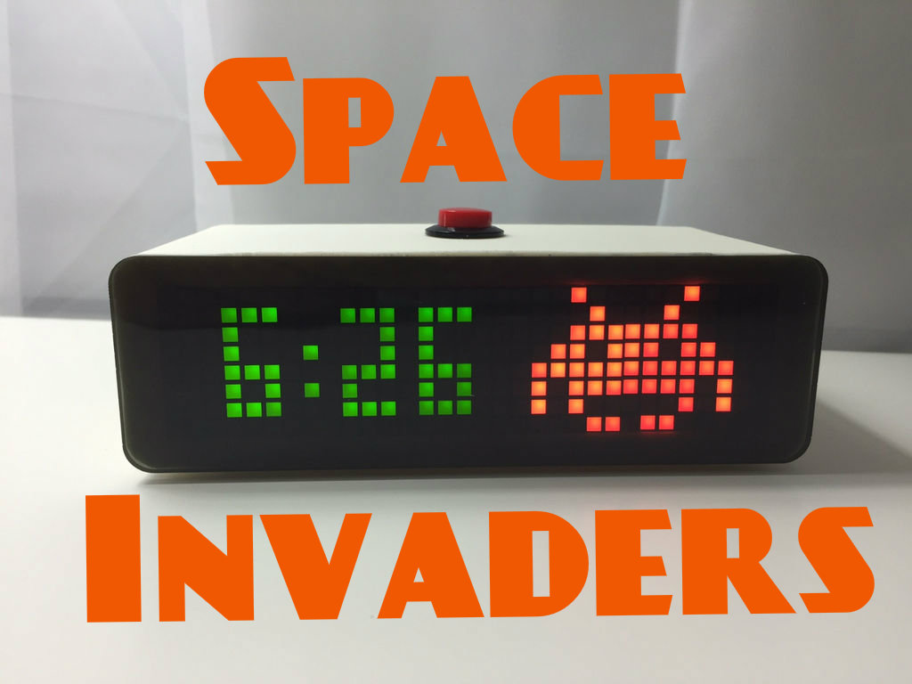
Many of us have played the classic arcade game Space Invaders. Here's a way to implement it into your daily life!
This nifty clock is packed with groovy animations and sound effects. It's perfect for your desktop, and will make work/study much more interesting.
Gather Materials
Parts and Components
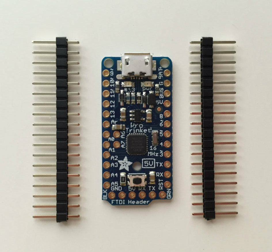
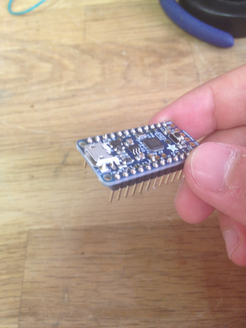
- Pro Trinket 5V (1)
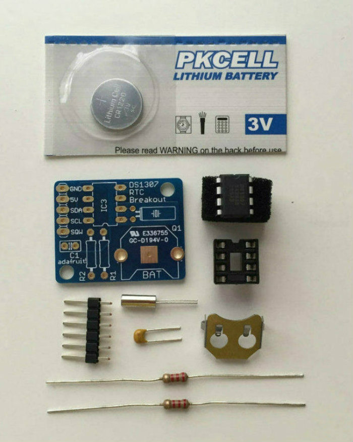
- DS1307 Real Time Clock Breakout Board (1)
- 8-Pin IC Socket (optional)
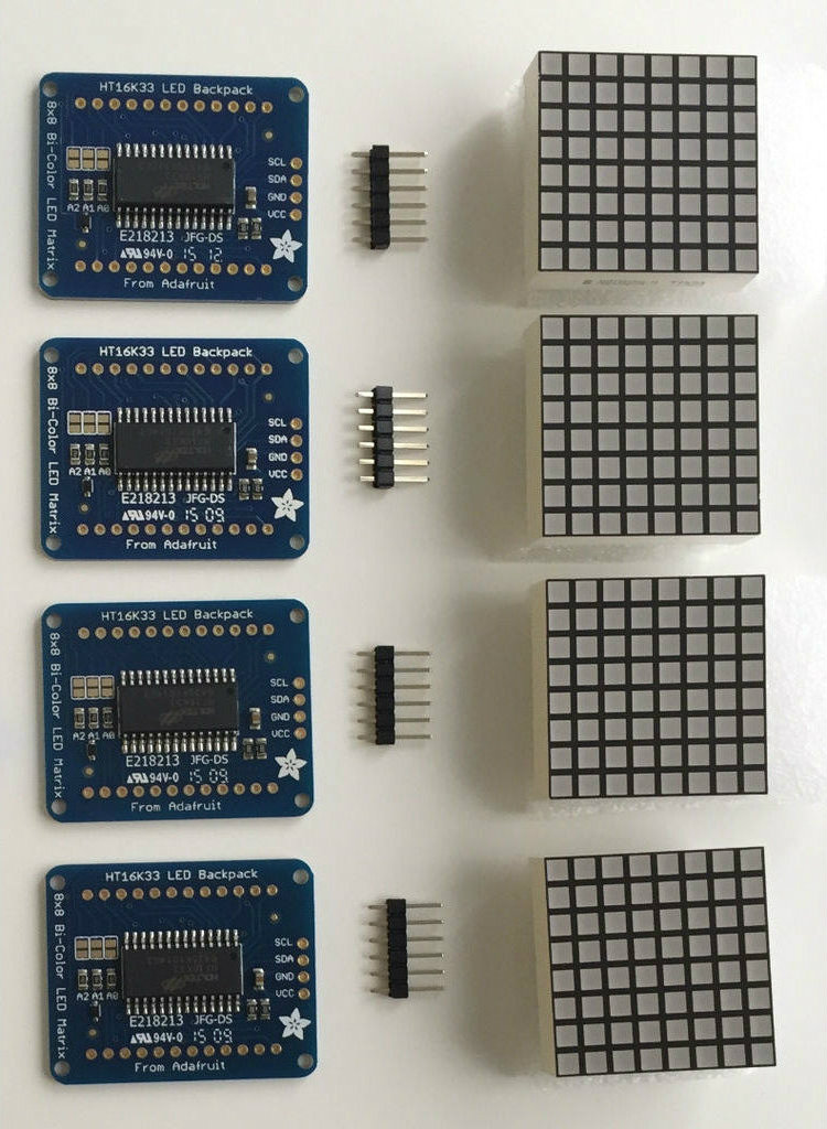
- Bicolor LED Square Pixel Matrix Backpack (4)
- 8Ω 0.5W Mini Speaker(1)
- Red Panel Mount Momentary Pushbutton (1)
- Assorted Heat-Shrink Tubing
- Panel Mount 2.1mm DC Barrel Jack (1)
- 5V Switching Power Supply (1)
- 20-22 AWG Hookup Wire
- Half-sized Perma-Proto Breadboard (1)
Note: You do not have to use Adafruit's Pro Trinket. Any Arduino-based 5V microcontroller should work as long as it has enough I/O pins and fits in the project enclosure.
Tools
- Soldering Iron (with solder of course)
- Helping Hands or PCB Vise
- Needle-nose Pliers
- Sand Paper
- File
- Hot Glue Gun
- Loctite 5-minute Epoxy
- Computer
- Micro USB Cable
Designing the Enclosure
In addition to the inner electrical workings, you will need a nice looking enclosure. This consists of three major parts: the clock body, the clock back, and the clock face. The body and the back are both 3D printed ABS (if you do not have a 3D printer, I highly recommend 3D Hubs). You will need to order the laser cut face with Ponoko; just upload the attached svg file and checkout.
Note: When ordering the laser cut acrylic from Ponoko, it is important that you select "Acrylic - Gray Tint" as the material, "3.0 mm" as the thickness, and "P1" as the size.
Prepare Software and Code
To begin with, make sure you have the latest version of the Arduino IDE.
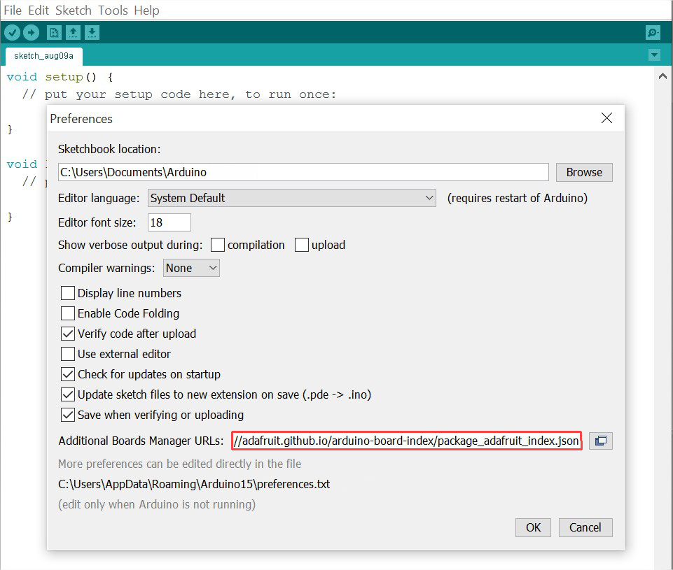
You must then install the proper software to support Adafruit microcontrollers (assuming you are using the Pro Trinket). Open up Preferences and paste the following link into the box for Additional Boards Manager URL:
https://adafruit.github.io/arduino-board-index/package_adafruit_index.json
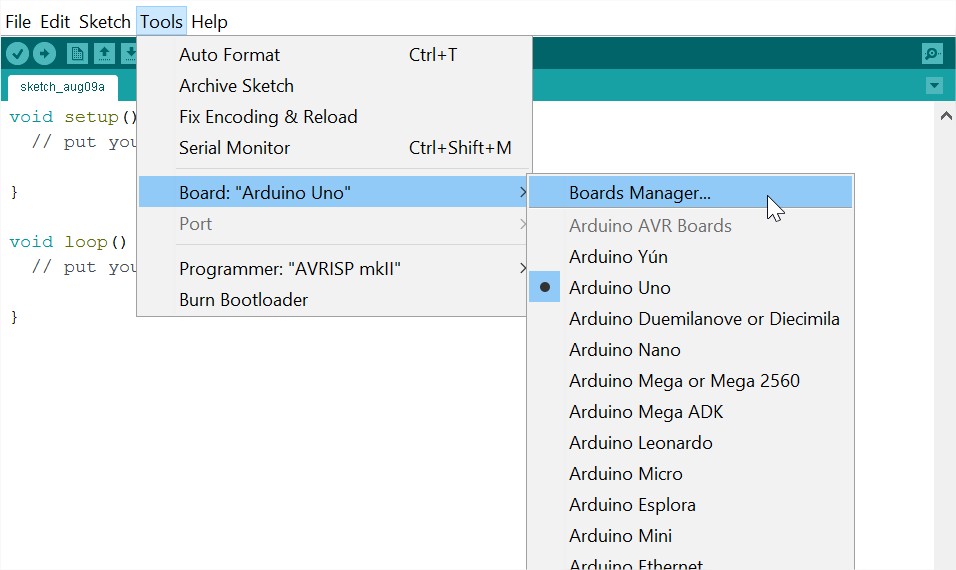
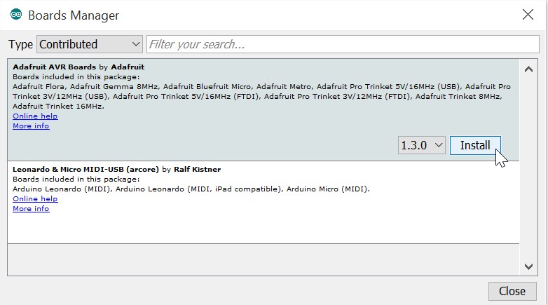
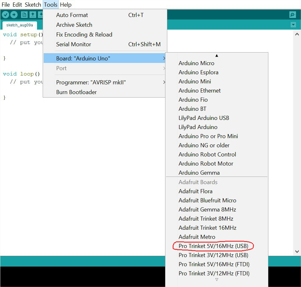
Go to Tools > Board > Board Manager and install "Adafruit AVR Boards" under Contributed. Now when you open Tools > Board, you should see a whole list of new Adafruit boards. Select the option for "Pro Trinket 5V/16MHz (USB)", then set Tools > Programmer to "USBtinyISP".
You will also need to install the following libraries through the library manager:
- RTClib
- Adafruit_LED-Backpack
- Adafruit_GFX
For more information on working with Arduino libraries check out this tutorial.
After you have properly set up the IDE, download the attached Arduino file and upload it to your Pro Trinket.
Note: To upload code to the Trinket, it must be in bootloader mode (indicated by a pulsing red LED). To put the Trinket into bootloader mode, simply press the reset button.
Downloads
Preparing the Breakout Boards
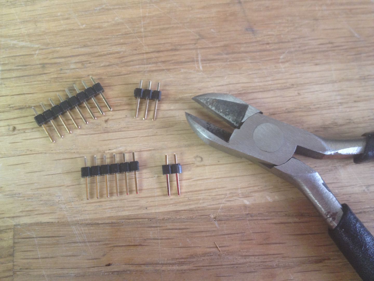
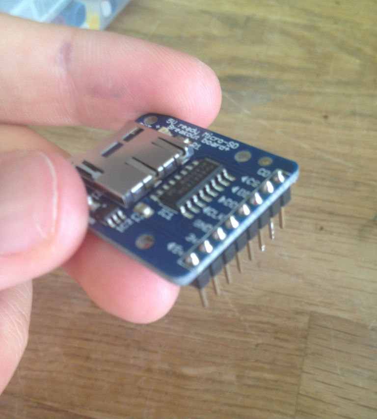
You will need your soldering supplies for the next three steps. While your iron heats up, start cutting off the number of header pins needed for each breakout, then solder them on. Using a breadboard helps a lot.
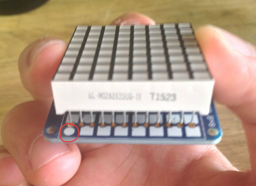
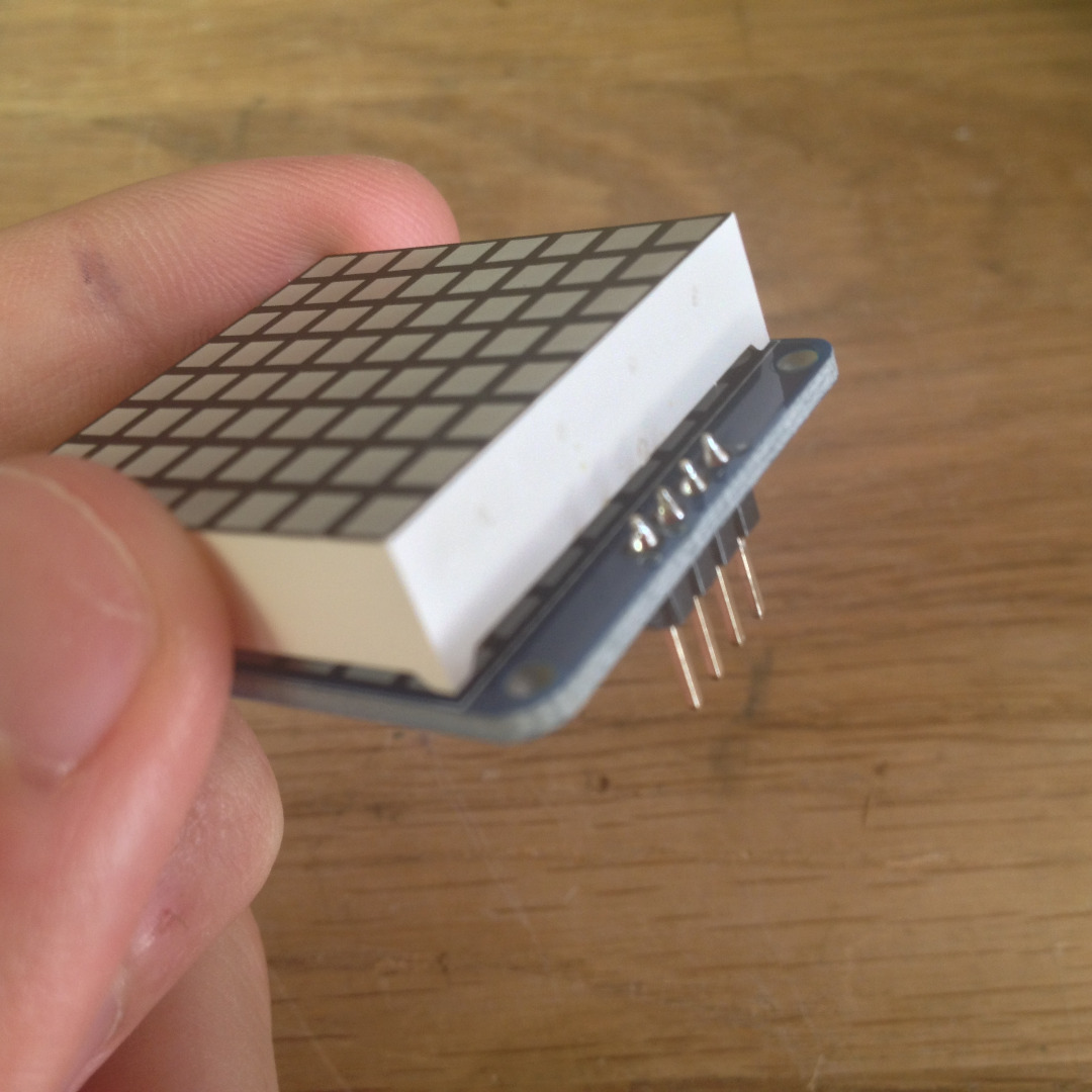
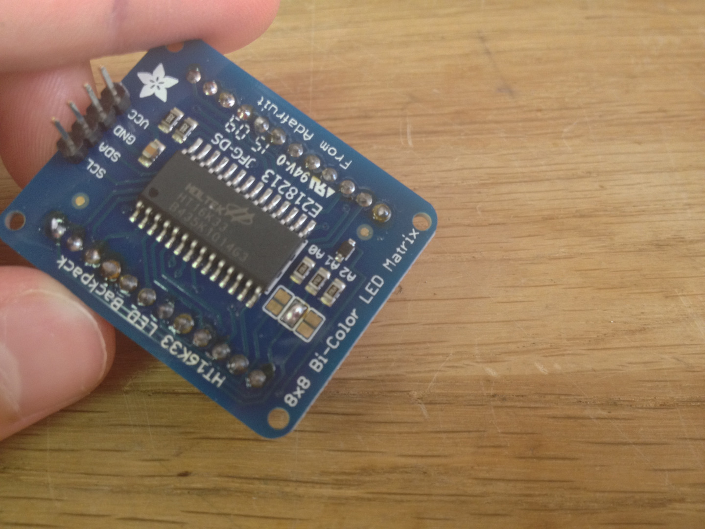
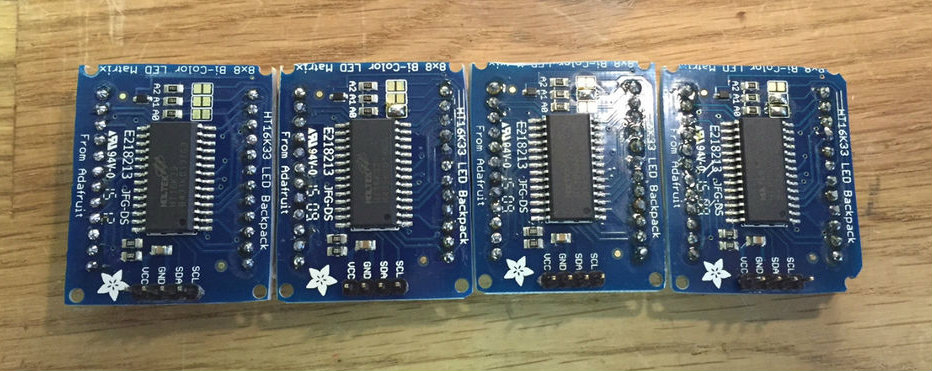
When soldering the LED matrices onto their backpacks, make sure the side with printed text is on the same side as the silk screen circle. On the back, short the I2C address pads as follows:
- A0 (address 0x71)
- A1 (address 0x72)
- A0 and A1 (address 0x73)
- None (address 0x70)
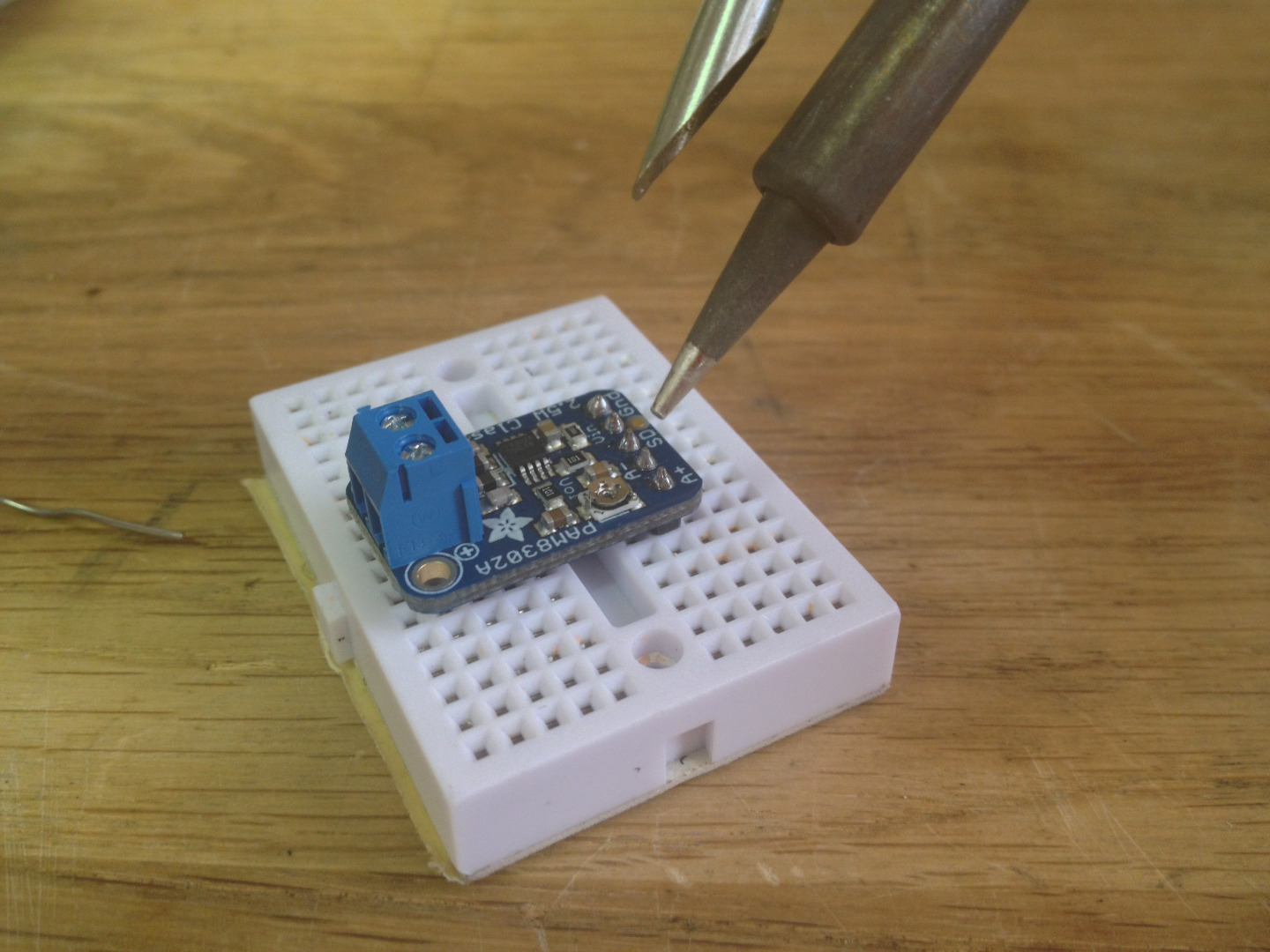
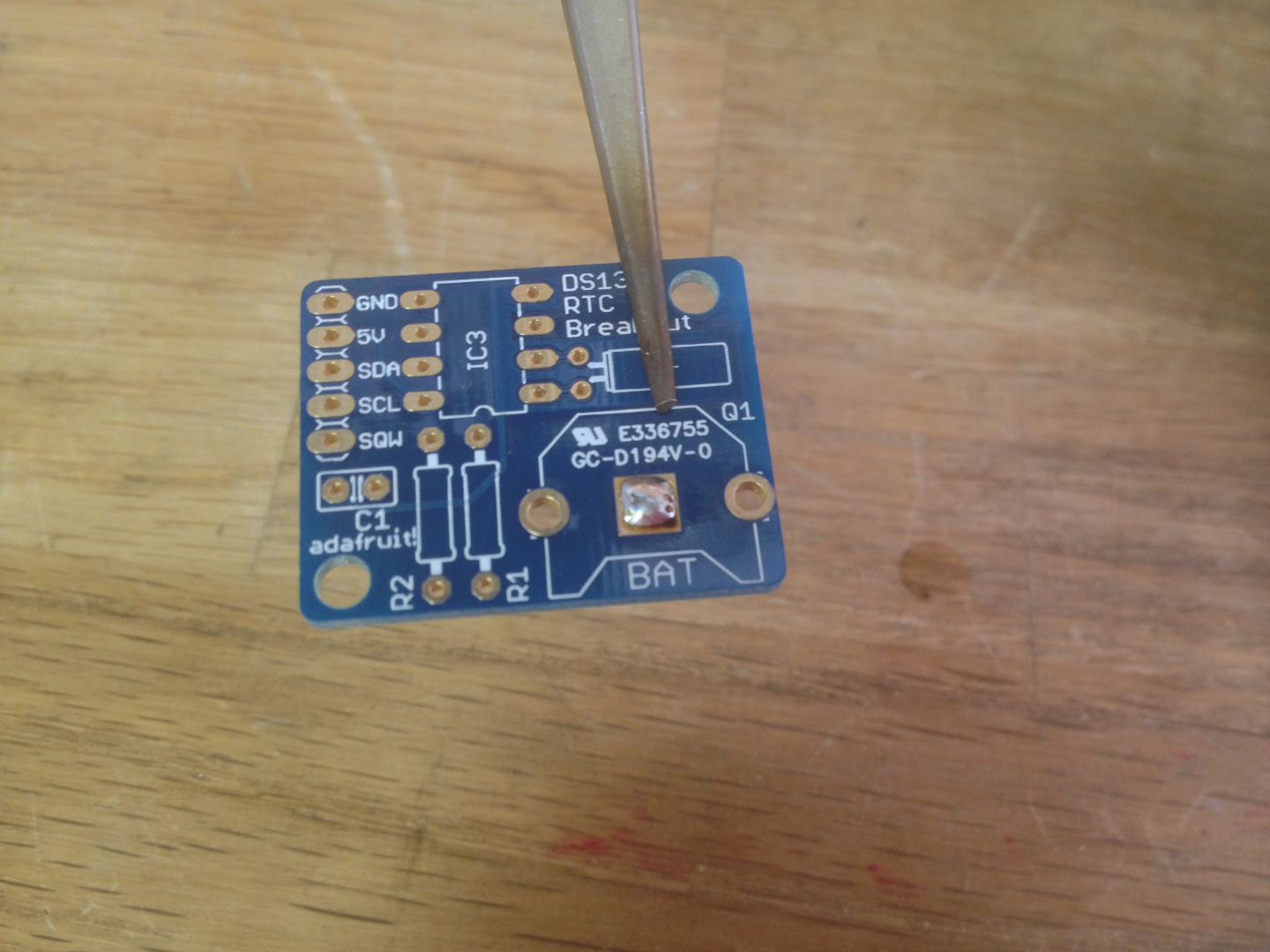
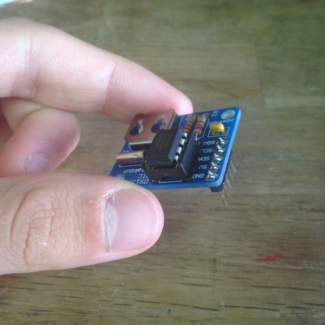
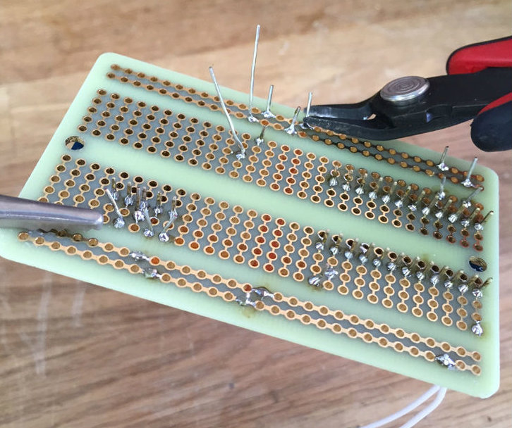
The Real Time Clock breakout requires some extra assembly. Start by melting a small lump of solder onto the battery holder pad (this will give the coin cell a nice and snug fit). Next, solder each component into their respective locations marked by the silk screen.
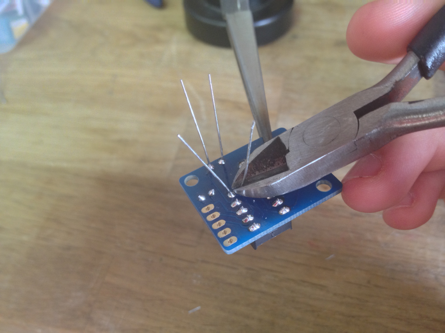
Don't forget to snip off any component leads.
Note: You may need to file down the sides of the backpacks so that the matrices sit flush next to each other.
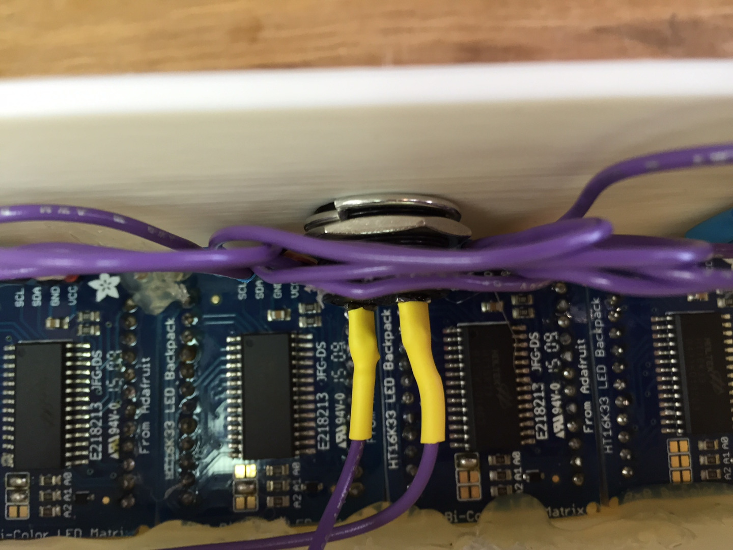
Solder Up the Display
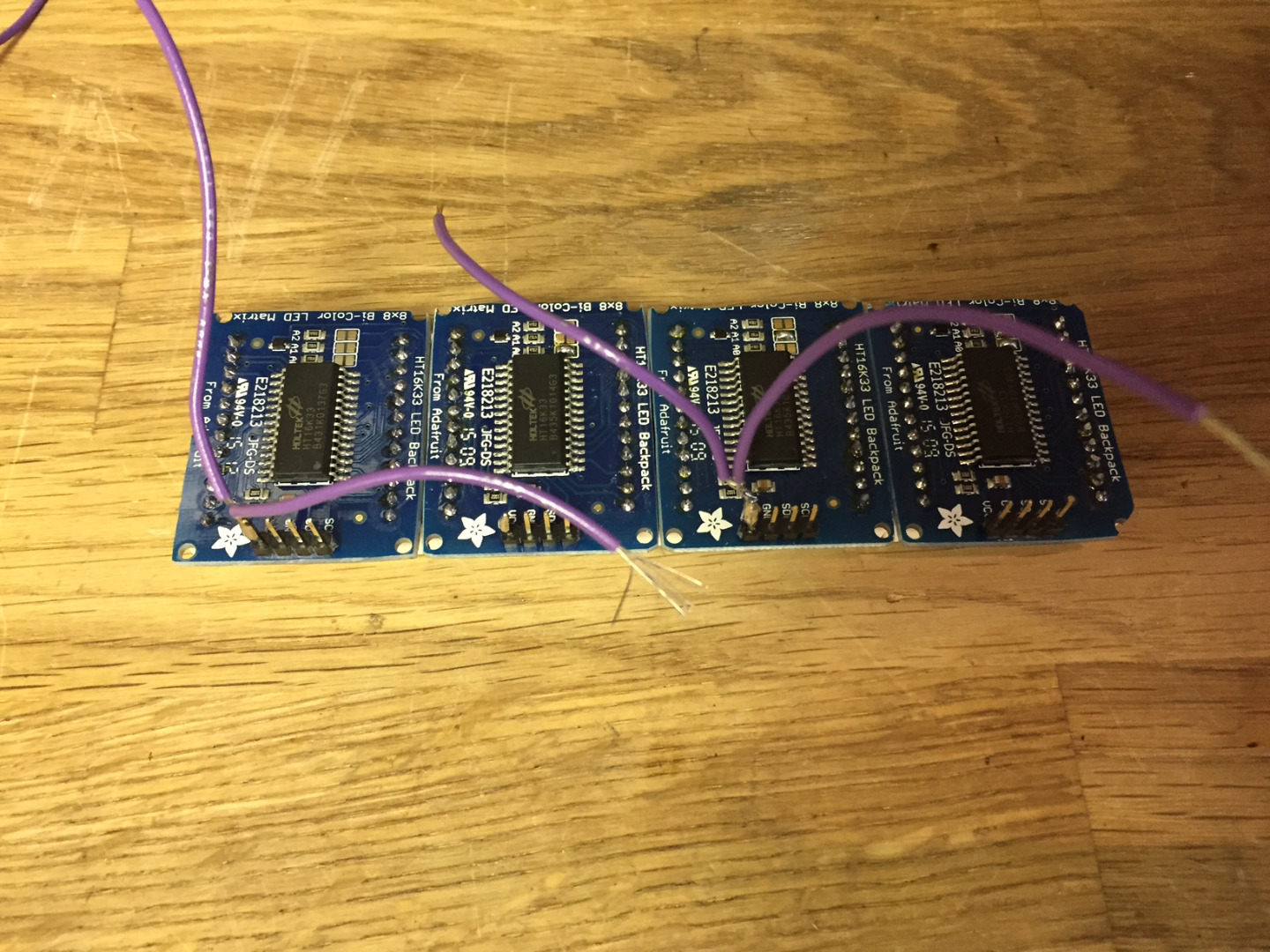
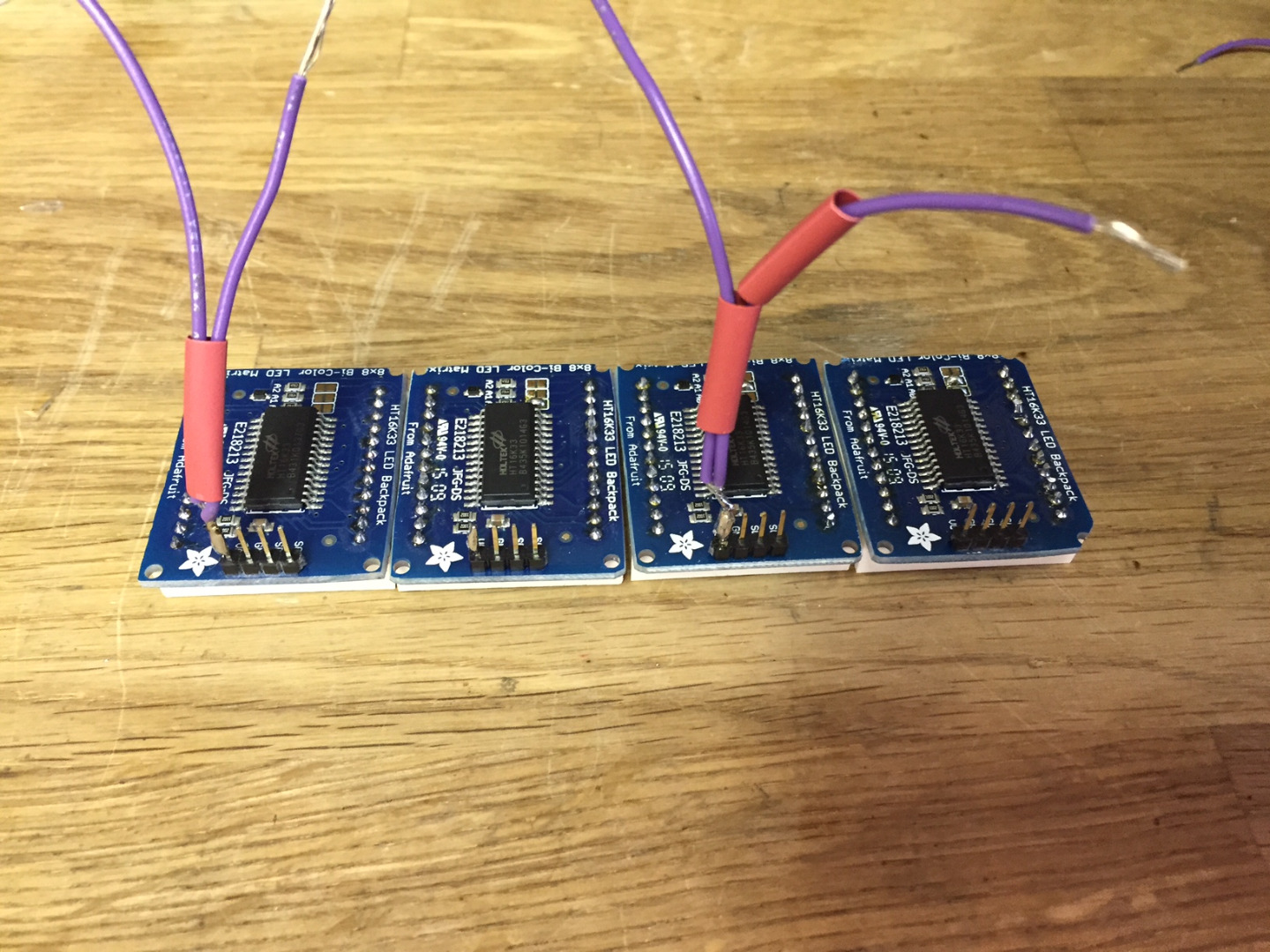
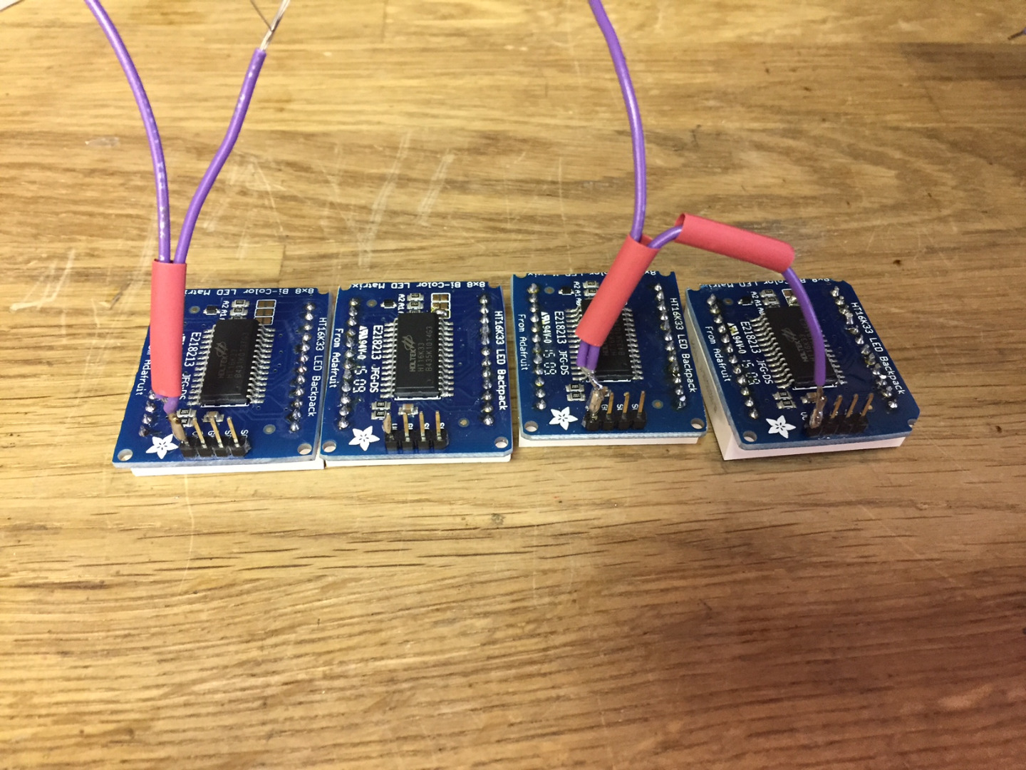
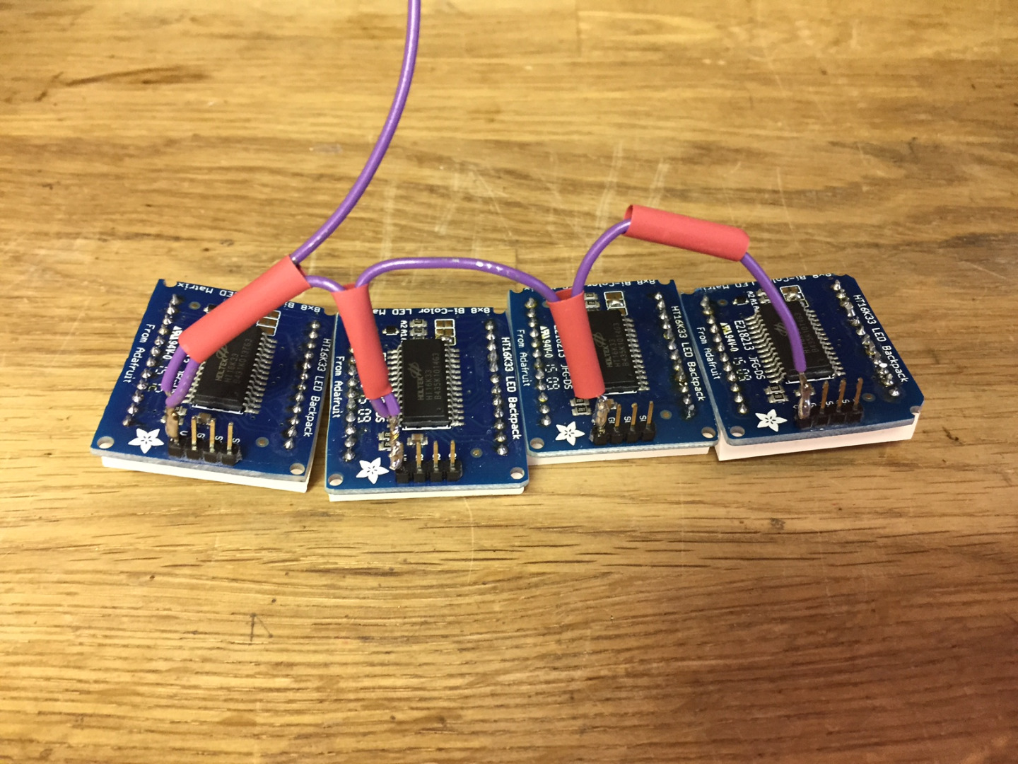
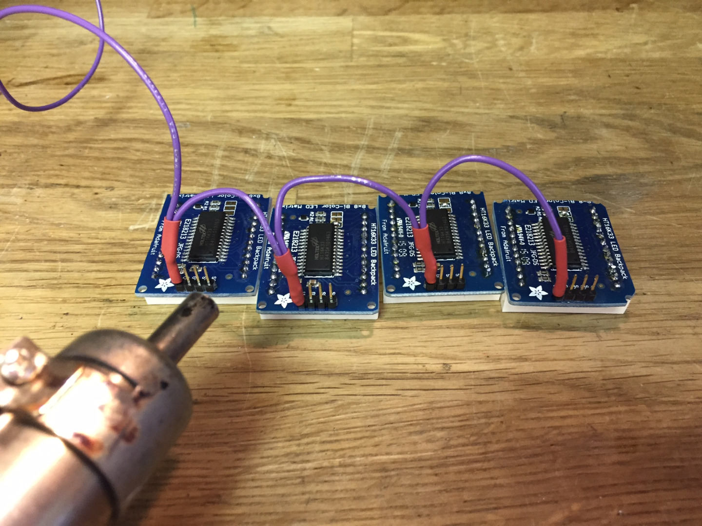
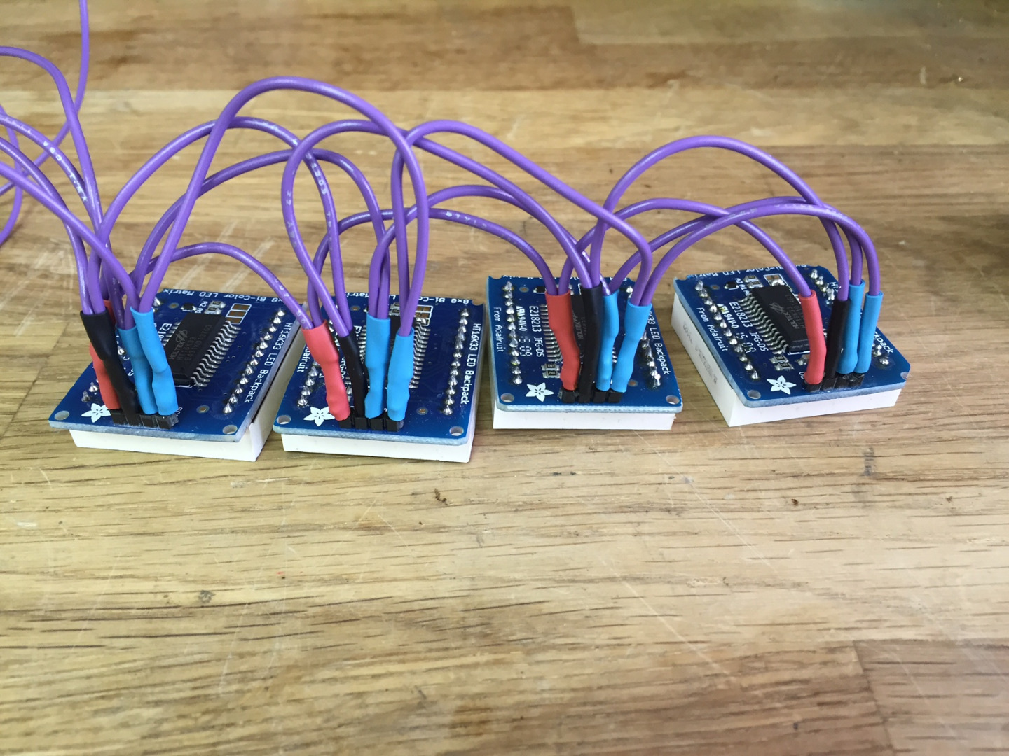
Lay the LED backpacks out from left to right so that the I2C addresses are in decreasing order. Solder up some hookup wire so that the Vcc pins of each backpack are all connected and a longer length of wire extends from the leftmost backpack. It is a bit tricky to get the the heat-shrink tubing on in the right order (see pictures above) so be very careful. Repeat for the GND, SCK, and SDA pins.
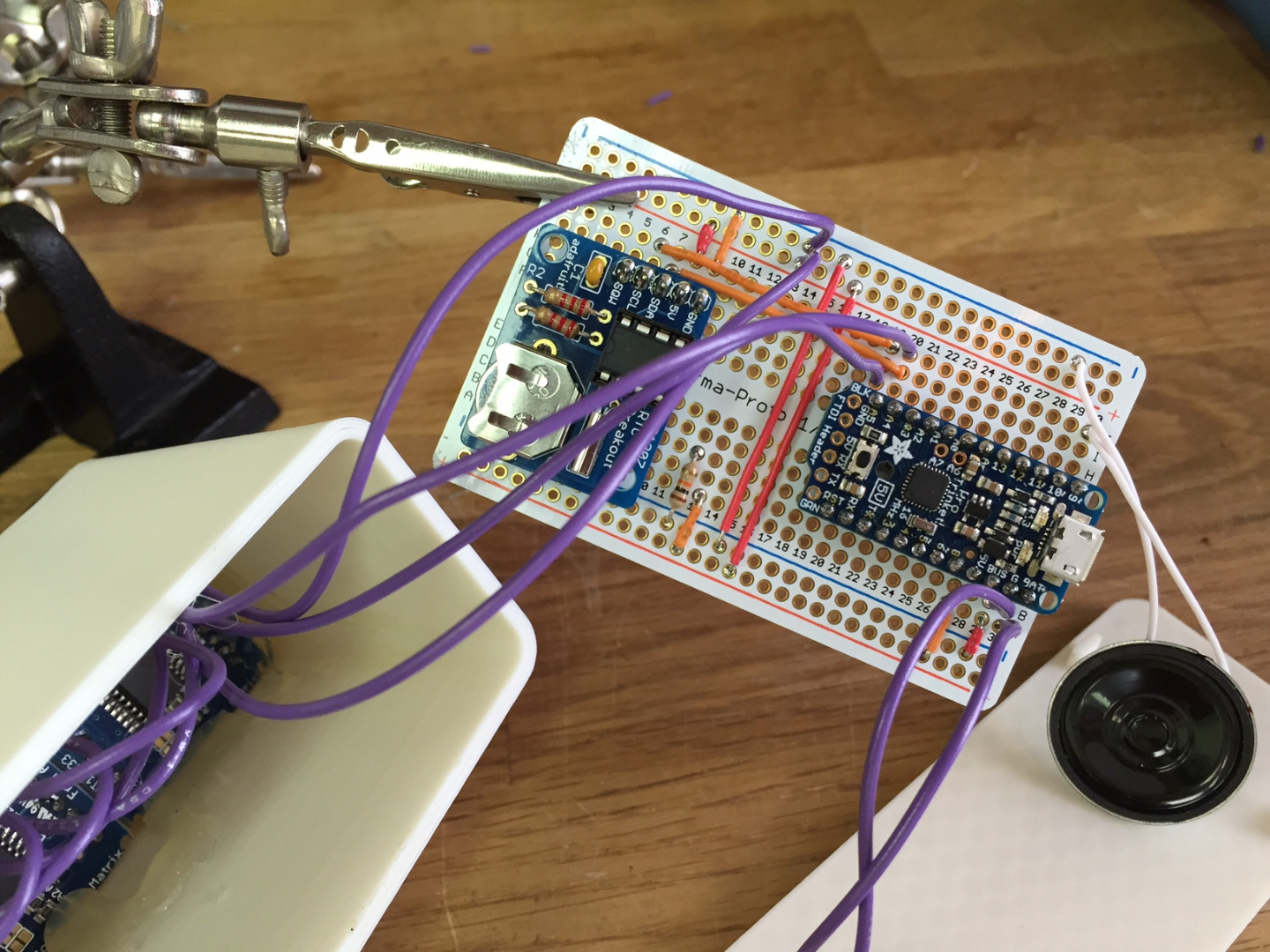
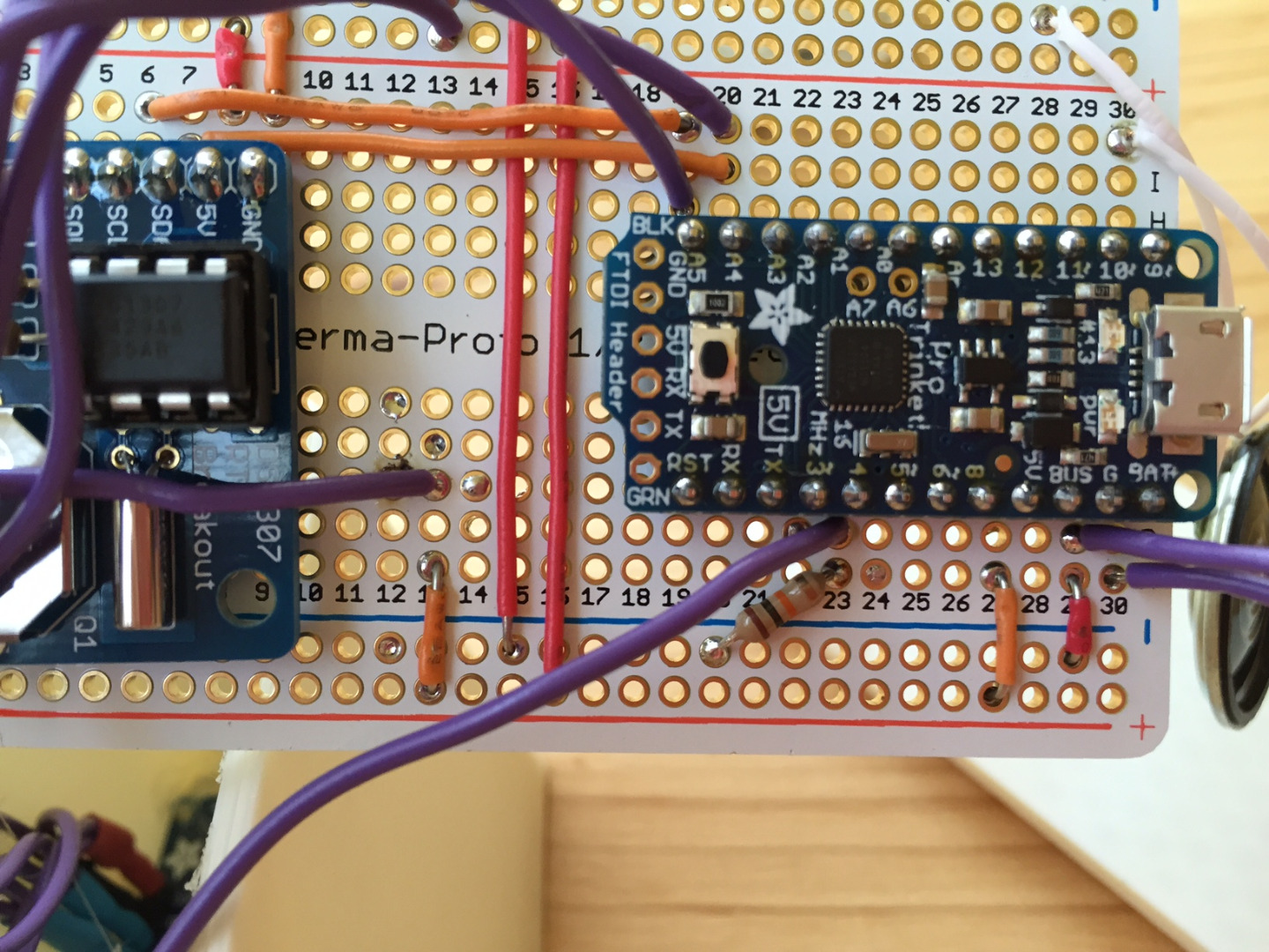
Solder Up the Main Board
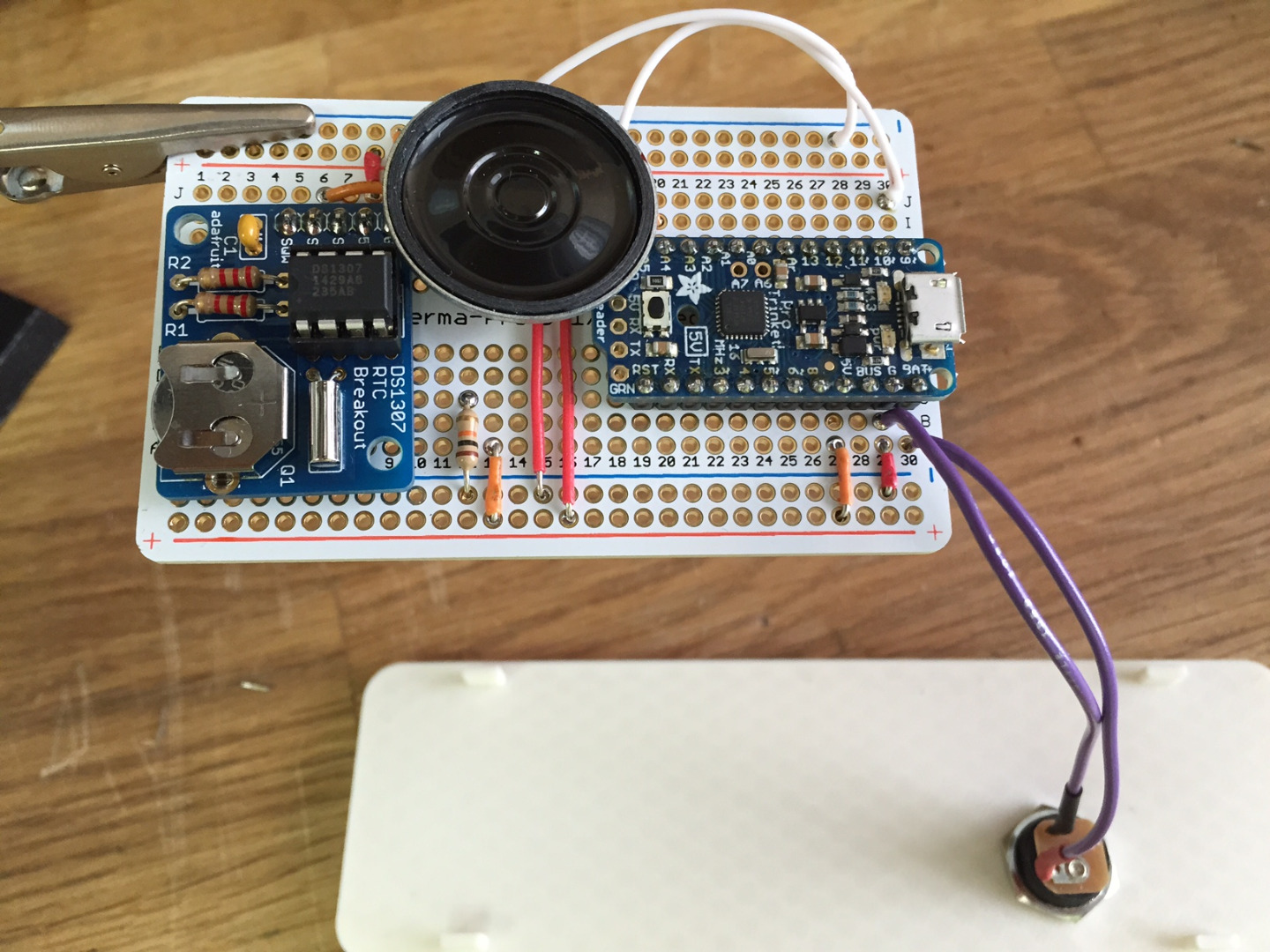
Now for the main circuit board.
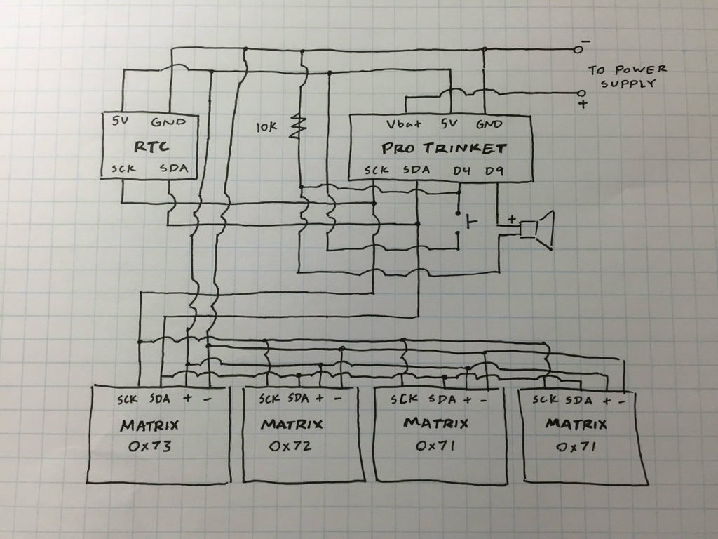
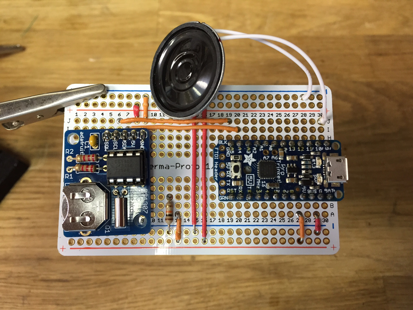
First, solder the Pro Trinket and RTC onto the proto-board. Then solder hookup wire to connect all 5V and GND pins. Also connect the I2C lines (SCK and SDA). Next add the speaker to digital pin 9 and the pull-down resistor to digital pin 4.
Once again, snip off any long leads.
Note: In some of the photos the placement of the pull-down resistor is erroneous. It should be connected to pin 4.
Putting It All Together
.JPG)
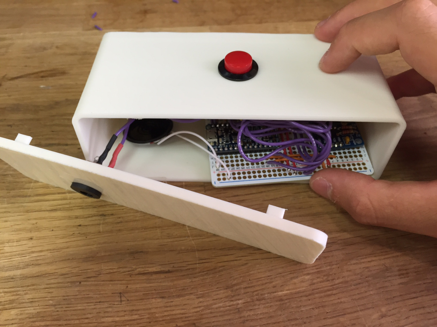
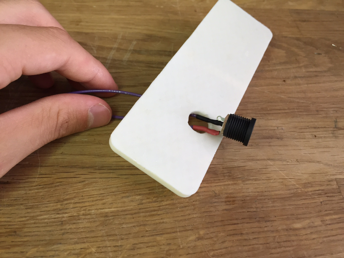
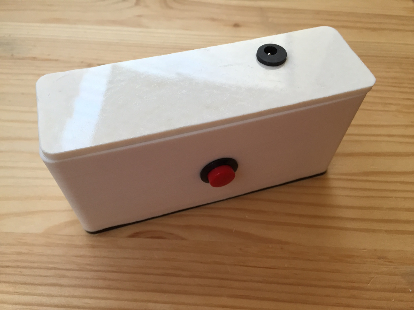
Fit the DC jack through the hole on the clock back and secure with the included nut. Then solder the leads to the Vbat and GND pins of the Pro Trinket.
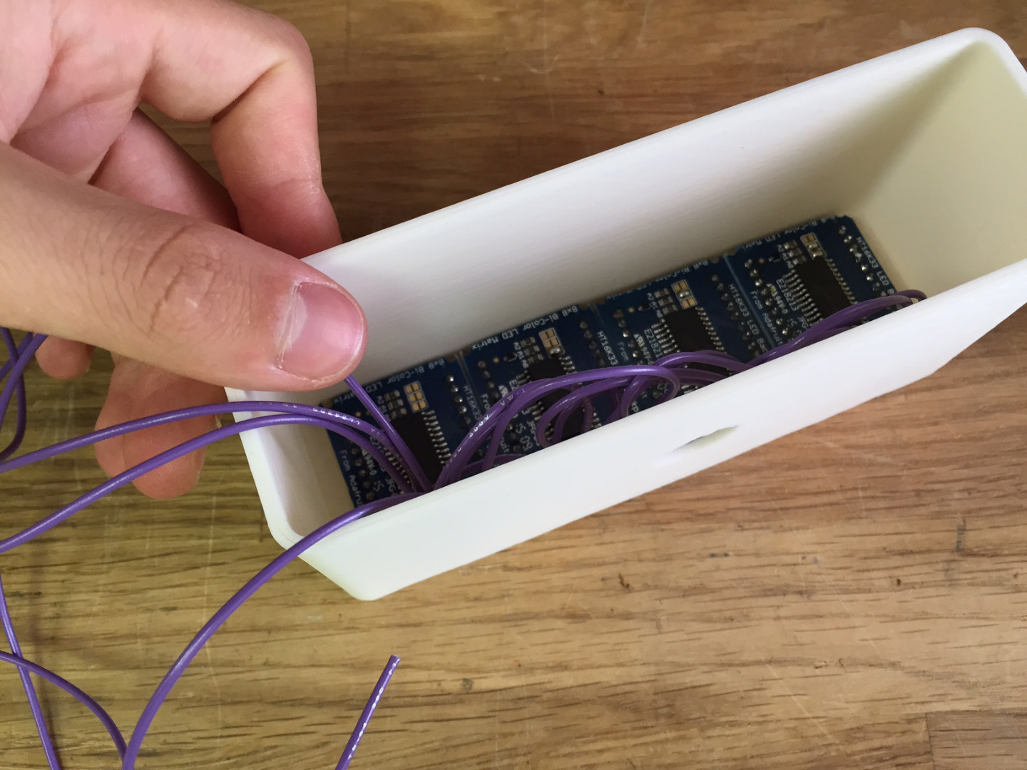
Use the glue gun to hot glue the LED matrices into the clock body (it will be a tight fit), and solder the four long wires to the 5V, GND, SCK, and SDA pins of the Pro Trinket.
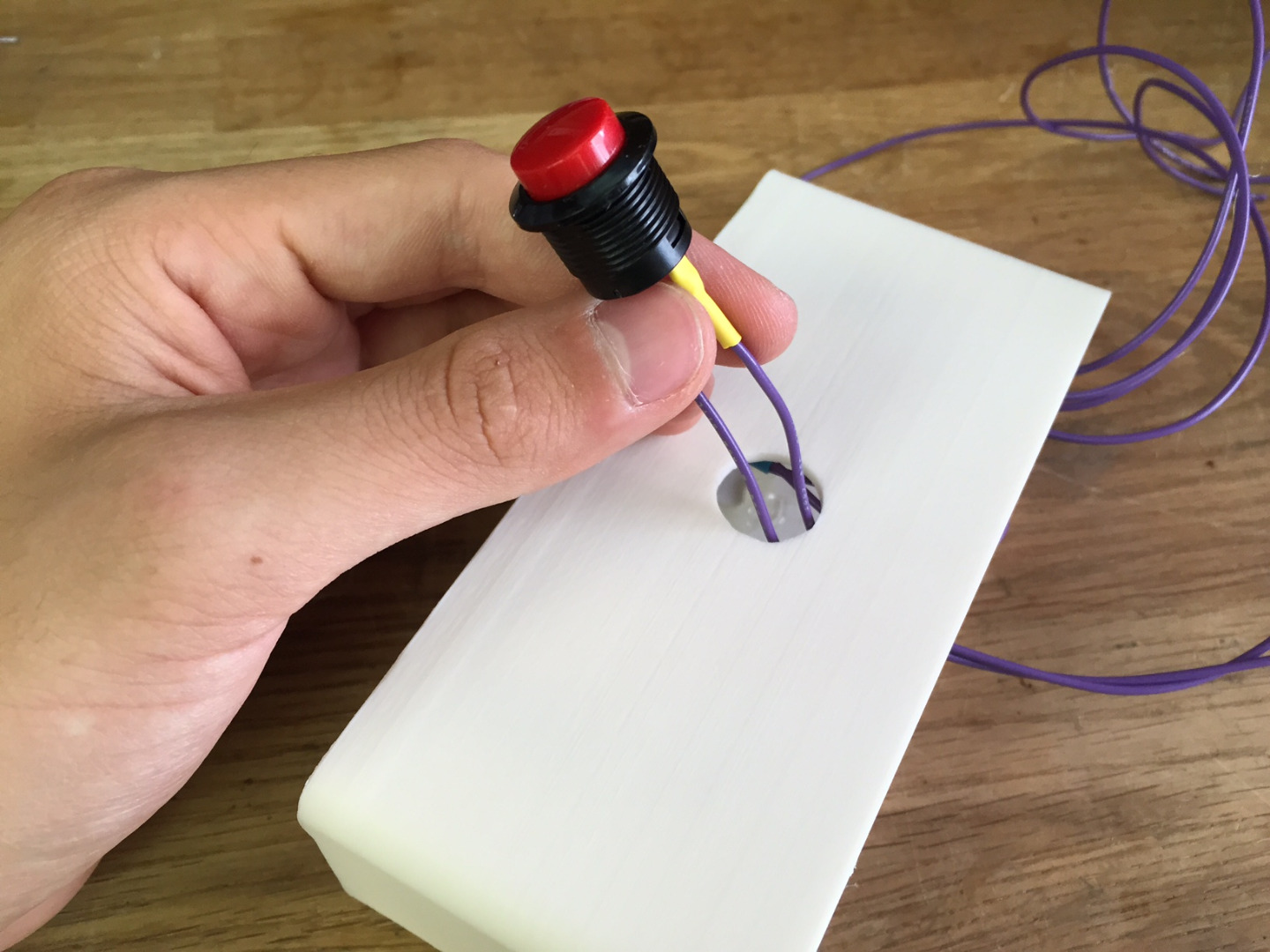
Install the button and secure it with the included nut. Solder one wire to positive power and the other to digital pin 4 of the Pro Trinket.
Finally, gently fit the proto-board and speaker into the clock body, snapping the clock back into place.
You have finished all the soldering for this project so take a quick break and grab a snack :)
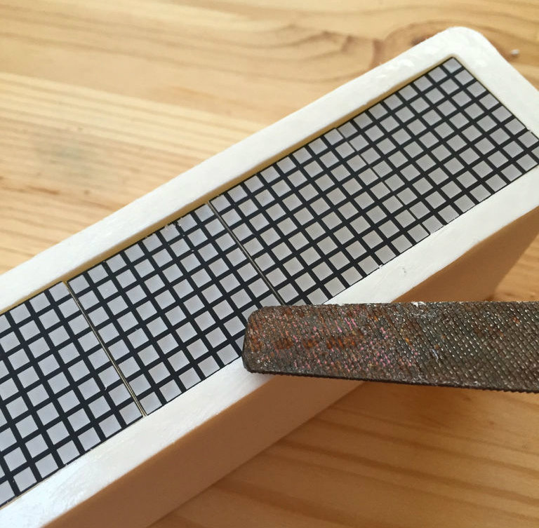
Final Touches
.JPG)
.JPG)
.JPG)
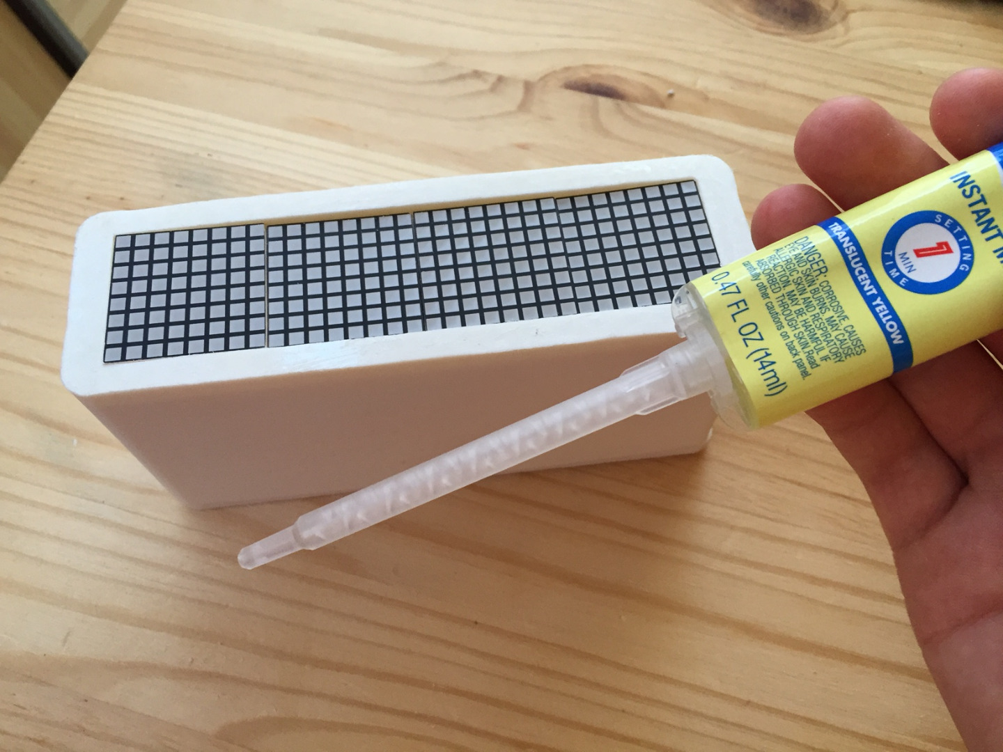
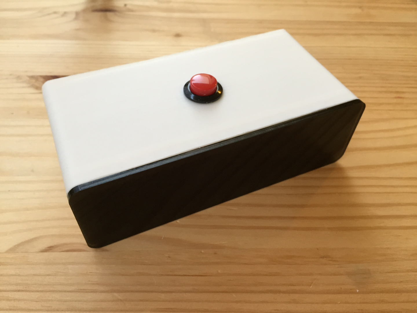
The last thing to do is to attach the clock face using some Loctite 5-minute Epoxy.
It helps to roughen up the area you will be gluing, which can be accomplished with a file.
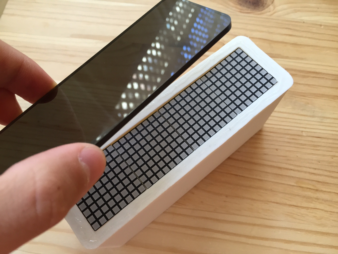
Following the directions on the bottle, apply a thin line of epoxy around the bevel of your clock. Carefully place the acrylic face on top, aligning the edges with that of the body. After the glue is set, you can lay the clock face down to dry.
Going Further...
Yoo hoo! You just built your very own Space Invaders desktop clock!
I hope you enjoyed this project, but don't stop there. I encourage you all to implement your own ideas and make this project even cooler!
In conclusion, I would like to give a special shout-out to the great Tomohiro Nishikado, designer and creator of the world's greatest arcade game.
EXTRA: I have added some modified files which should provide a better fit for the LED matrix backpacks. Keep in mind that they have not been physically tested yet, so their function is not assured.