Sound Activated Camera Flash
by Barely Painted in Circuits > Sensors
3045 Views, 17 Favorites, 0 Comments
Sound Activated Camera Flash
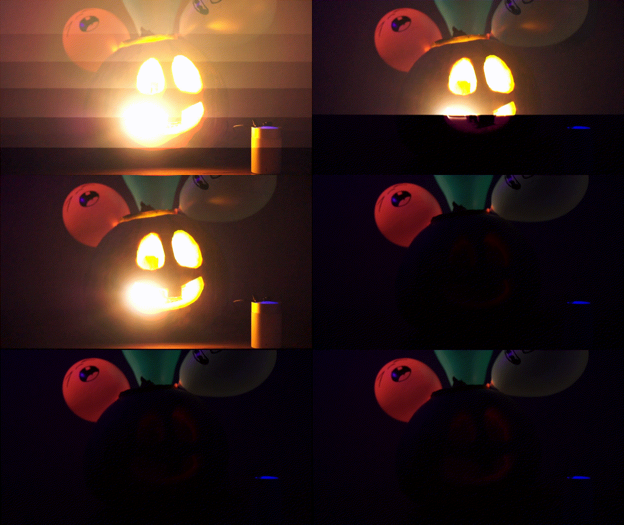
I show you how to make sound activated strobe light using Camera Flash. You can use this for Halloween party.
Watch Video
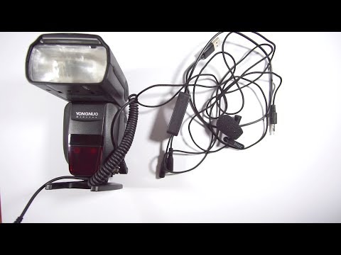
In this video you can see what result you’ll get in case if you decide make this project by yourself.
Timeline
- 0:07 - Preview
- 0:25 - Test Build
- 1:07 - Test
- 3:00 - Permanent Build
- 5:17 - Demonstration
Notice! Because frame rate and shutter speed limitations, video does not represent exact result, in real life this looks a tons better.
Prepare Components for Test Build
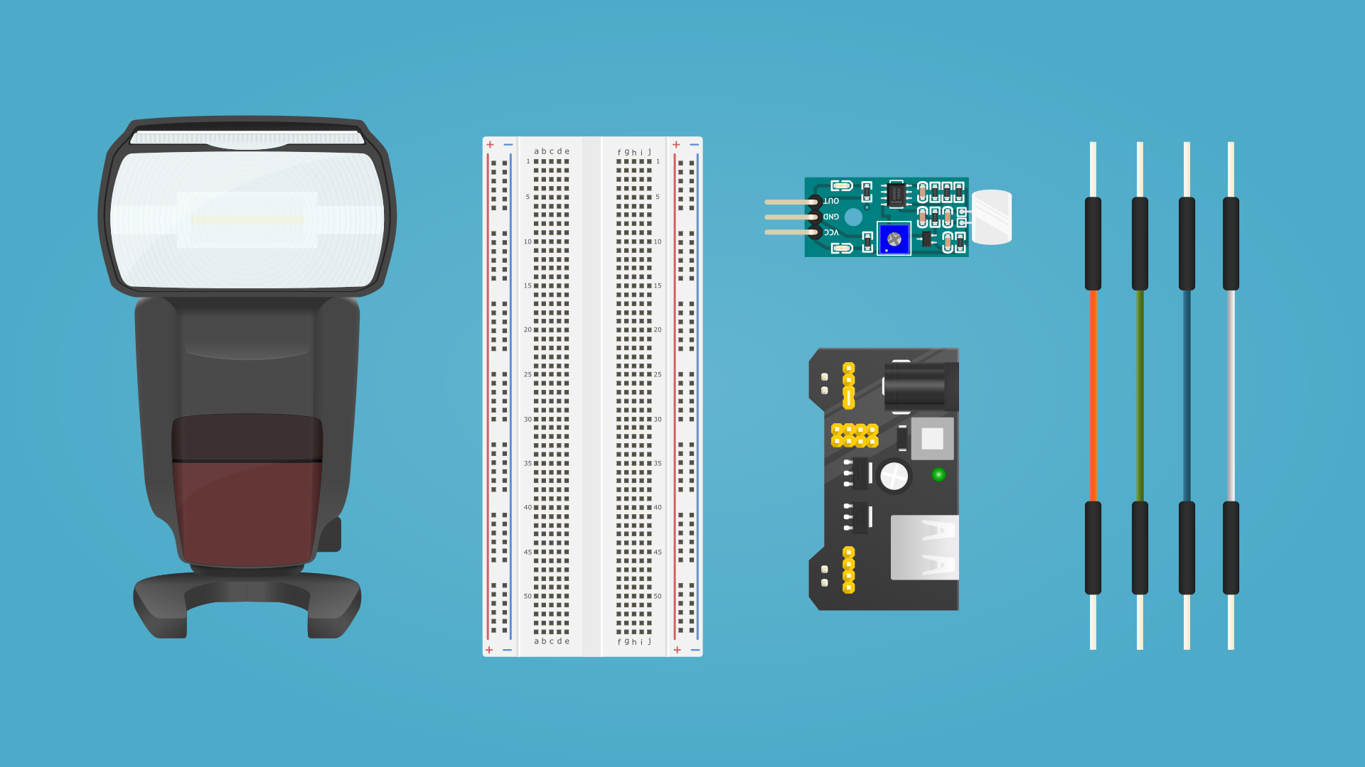
Components:
- On Camera Flash Light (you can use any flash light, for some flashes you’ll need additional adapter that allows connect trigger cable to 3.5mm socket) (x1)
- Breadboard (x1)
- Power supply for Breadboard (x1)
- Analog Sound Module (x1)
- Jumper (dupont) wires (x4)
- USB to Barrel Jack DC (5.5/2.1mm) Power cable (x1)
- Power Bank (any source of 5V DC) (x1)
Connect All Components
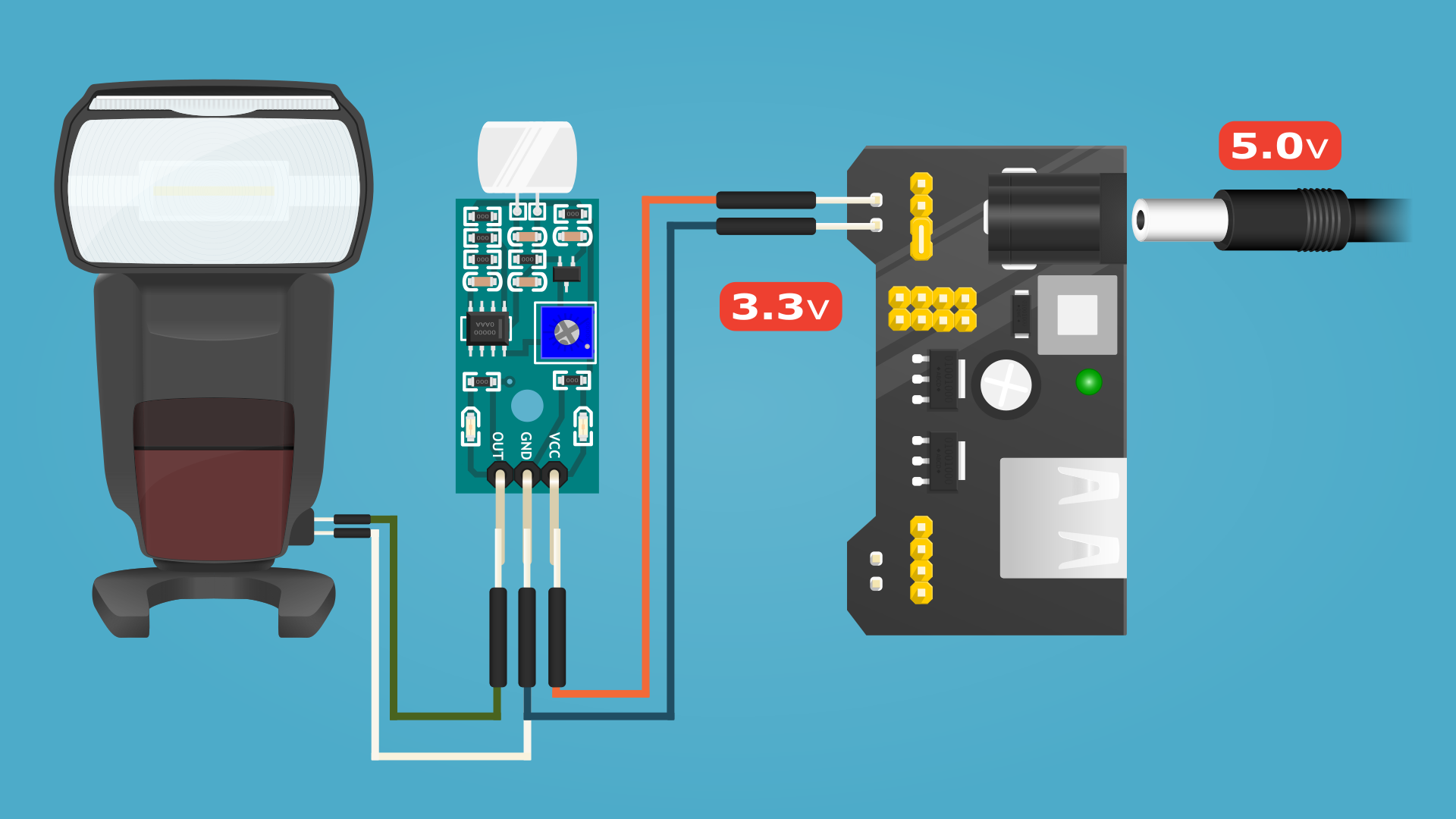
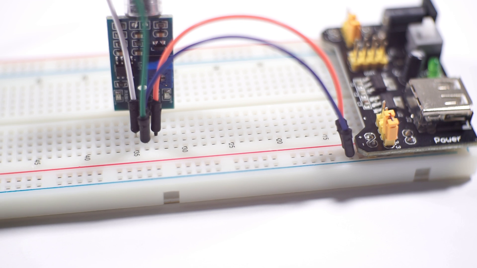
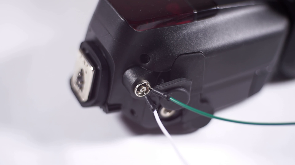
Connect all of this by using breadboard as you can see on the images above.
- Connect VCC input pin to the Positive out (Orange jumper cable on the image);
- Connect GND input pin to the Negative out (Blue jumper wire on on the image);
- Connect OUT pin to the Camera Flash Central (X-Sync/Trigger) pin (Green jumper wire on the image);
- Connect Negative org GND out to the Camera Flash Ground (White jumper wire on on the image);
- Connect 5V cable to the power supply board;
- Press On/Off switch on the power supply (Green LED should light up);
- Turn on Camera Flash.
In most cases by default, jumpers on the power supply, already setup on 3.3 volt out, but you can change this if your power supply board has 5.0v configuration.
Test
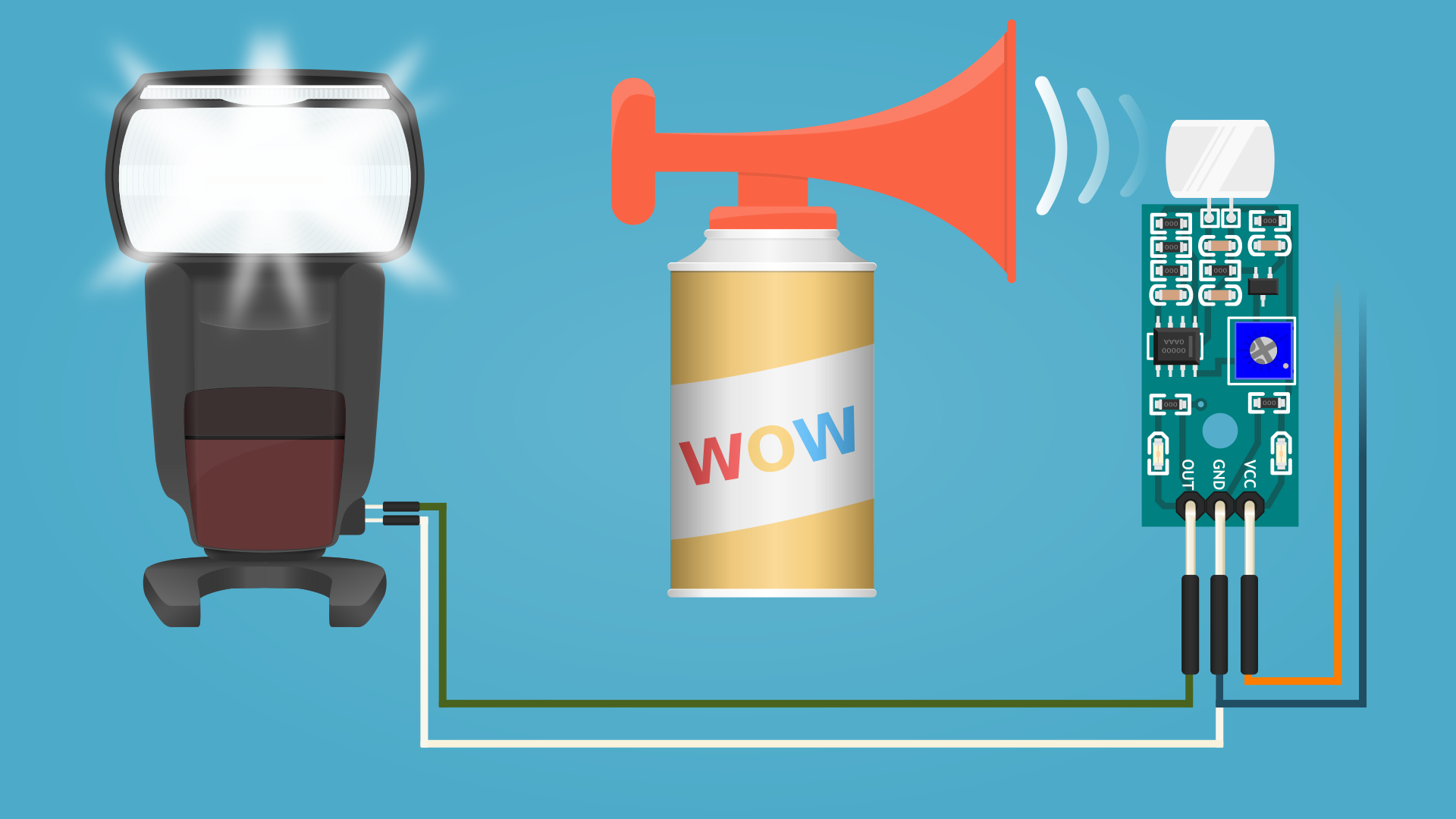
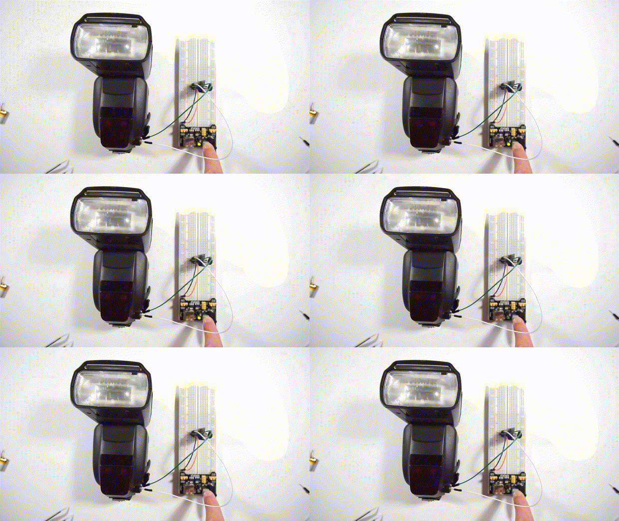
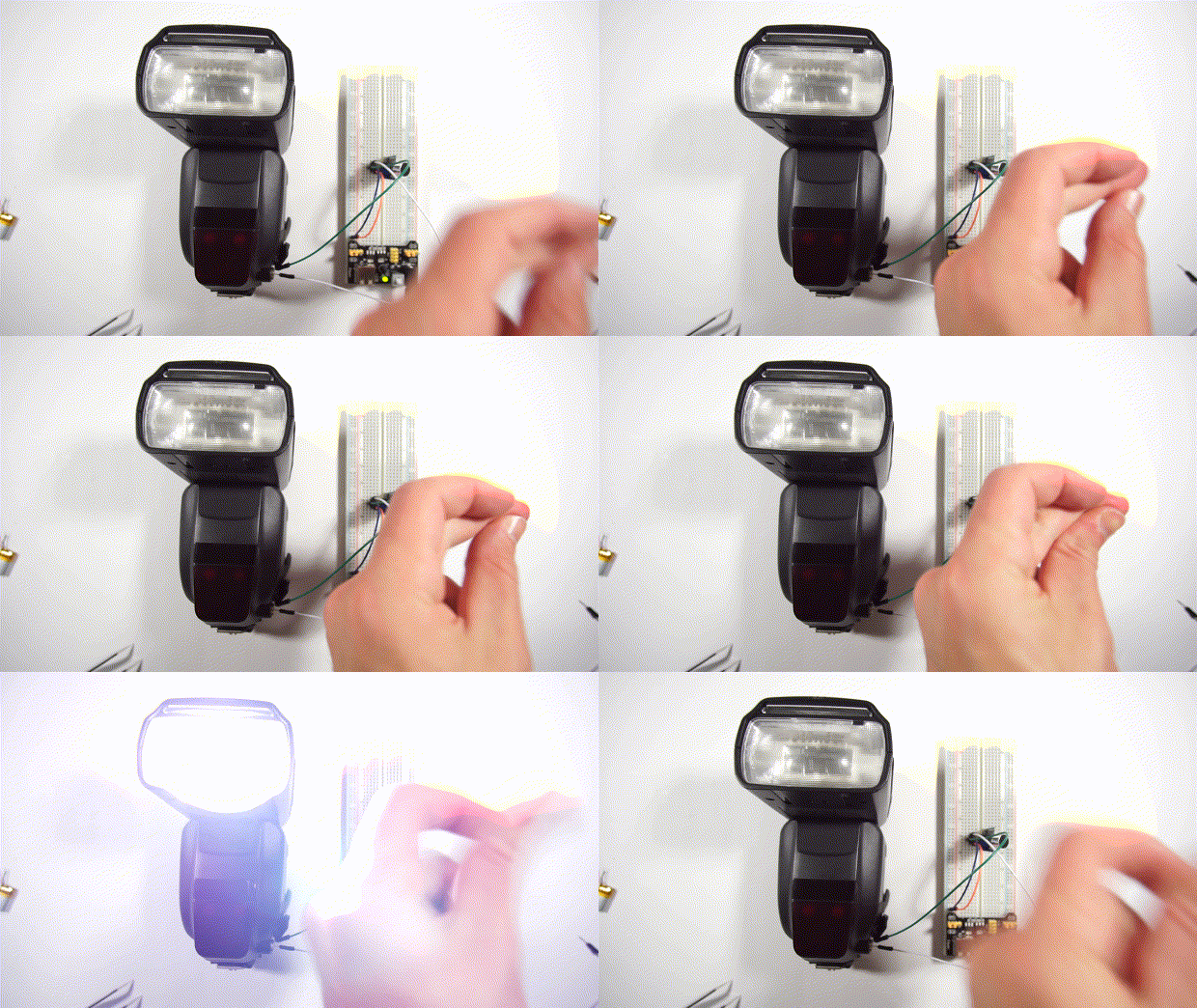
Make some noise (you can use air horn, fingers etc..). In case you don’t get any result, simply adjust potentiometer on the Sound Module.
Tools for this step: Cross Screwdriver.
Permanent Build
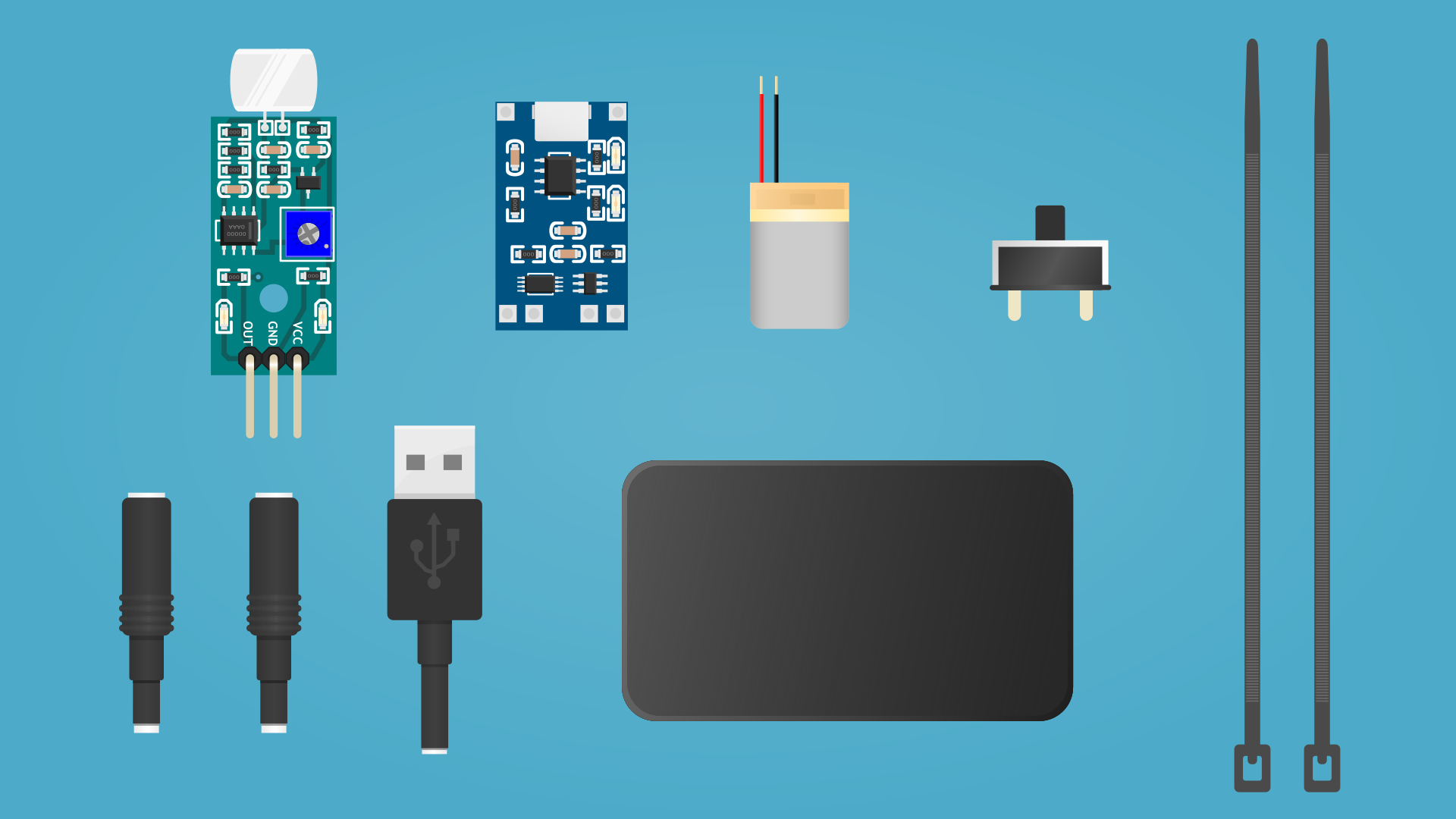
For permanent device additionally you’ll need:
Components
- Small SPST or SPDT Slide On/Off Switch (x1);
- 160 mAh 3.7 volt (approx 23Lx17Wx6.5H mm/0.9Lx0.7Wx0.3H in) LiPo Battery (x1);
- Micro USB 5V/1A LiPo Charging module (x1);
- Project Box (55Lx35Wx15H mm/3.93Lx2.36Wx0.98H in) (x1);
- Zip ties (3.6mm/0.14in wide) (x2);
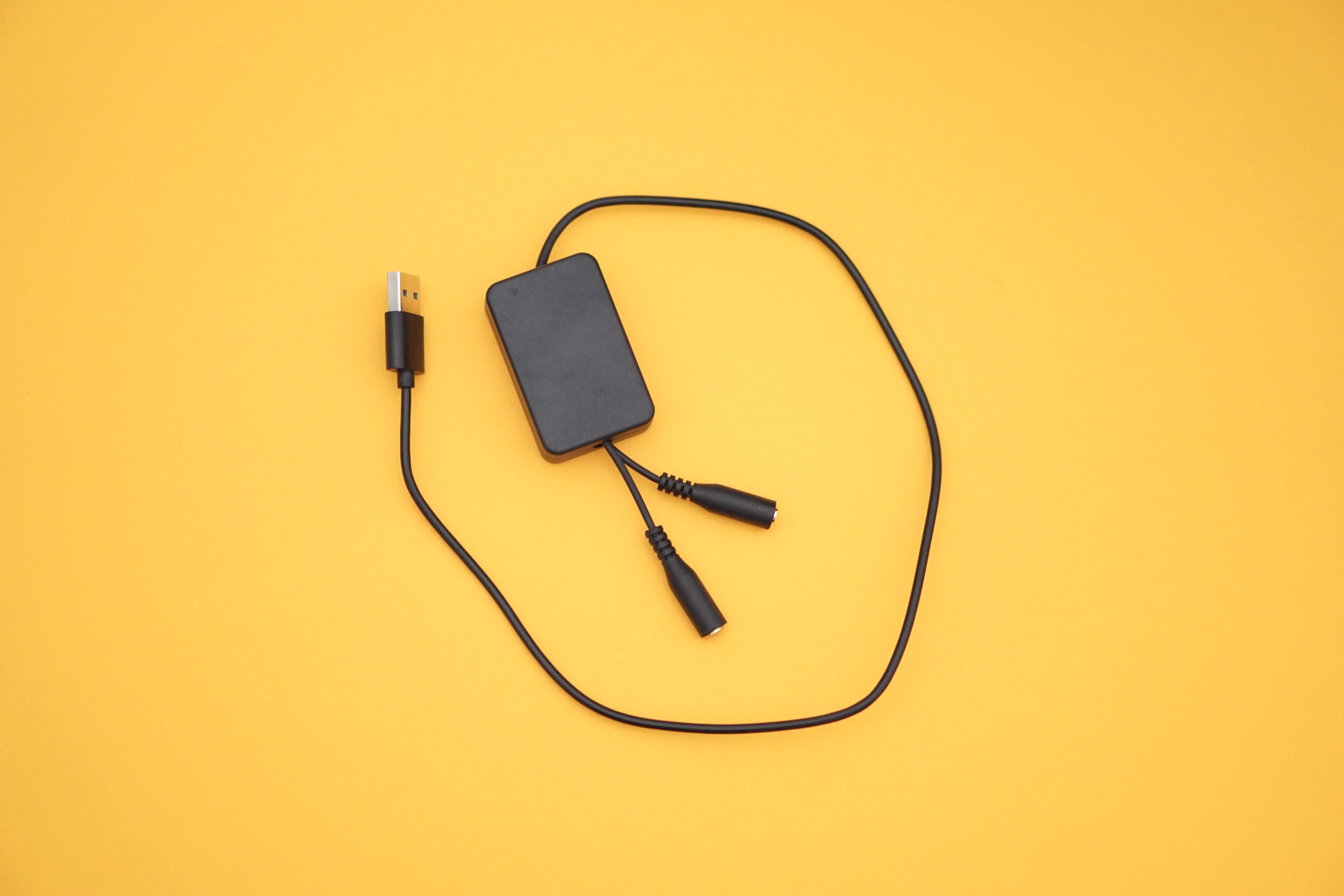
- USB Type A male cable 1m/0.3ft length (x1);
- Headphone splitter with two 3.5mm female jacks (approx 5cm/2in length) (x1);
- Wires (You can use wires from USB cable).
Tools
- Side Cutters;
- Soldering Iron (60W);
- Solder Wire;
- Flux Paste;
- Desoldering Wick;
- Helping Hand;
- Tweezers;
- Hot Glue Gun and Refills;
- Cross Screwdriver;
- Protective Gloves;
- Wire Strippers.
Remove Unnecessary Parts
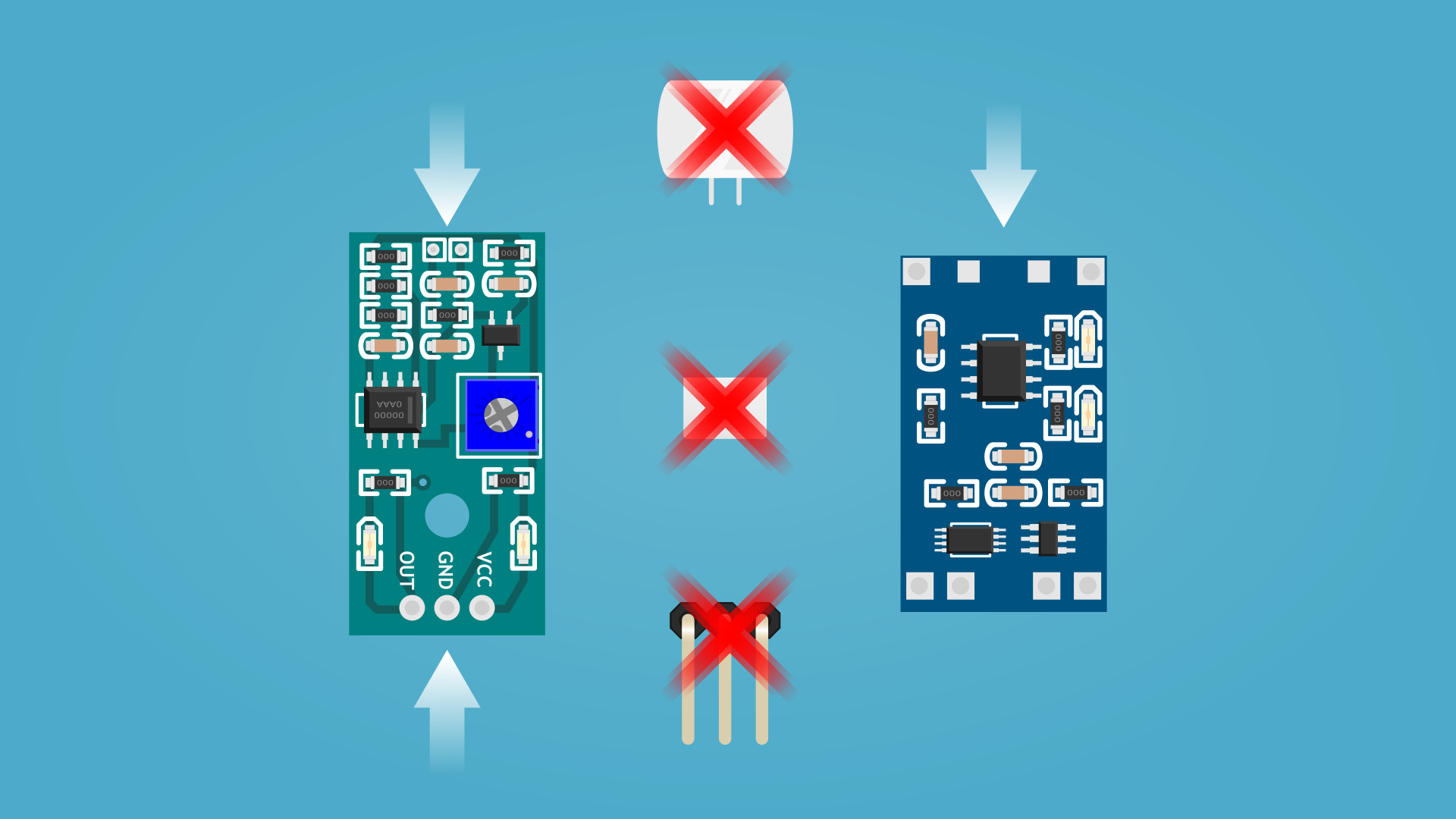
- Desolder microphone from Sound Module;
- Desolder connection pins from Sound Module;
- Desolder micro USB port from Charging Module (not necessary)
- Cut at least 15cm/6in USB cable with USB Type A male connector;
- Cut at least 5cm/2in (2x) 3.5mm female connectors headphone splitter cable.
Tools for this step: Side Cutters, Wire Strippers, Desoldering Wick, Protective Gloves.
Join All Components
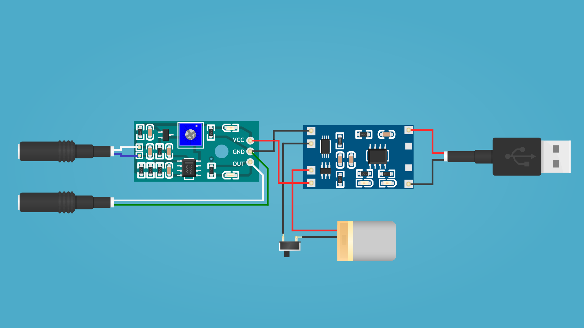
- Solder USB connector to the charging module
You only need black and red wires from USB cable (in this case red is positive, black negative).
- Solder 3.5mm Out jack for Camera Flash
From 3.5mm jacks we only need 2 wires, ground wire (wire without jacket “Bare Copper”, but coated in some sort of protective lack) and signal wire. Because our connector has 2 channels we should fiend only left channel, in most cases it has Green jacket. Also, you can fine right connector by using multimeter.
Solder one wire to the GND pin other to the OUT pin (in this case polarity does not matter).
- Solder 3.5mm Mic Input jack for External Microphone
Process the same as for Came OUT jack, simply solder two wires instead of built in Mic.
- Solder Battery
On the charging module you can found two point wit “B+ and B-” markings, this points intended for battery connection.
- Solder On/Off switch
You can solder On/Off switch between battery “Negative” out (in this case our device will not discharge battery while it not in use) but still should work by using USB connector.
- Solder Charging Module to the Sound Module
Solder negative out from the charging module to the GND pin on the Sound module and positive out to the VCC pin.
Tools for this step: Side Cutters, Soldering Iron, Solder Wire, Flux Paste, Helping Hand,
Tweezers, Protective Gloves.
Protect Cables
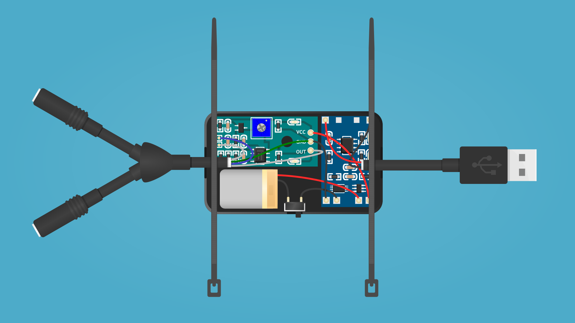
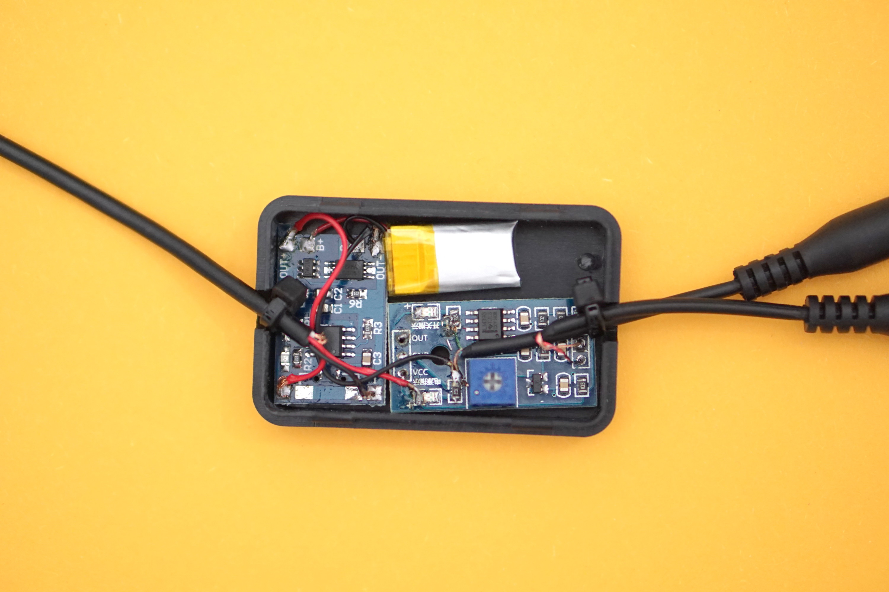
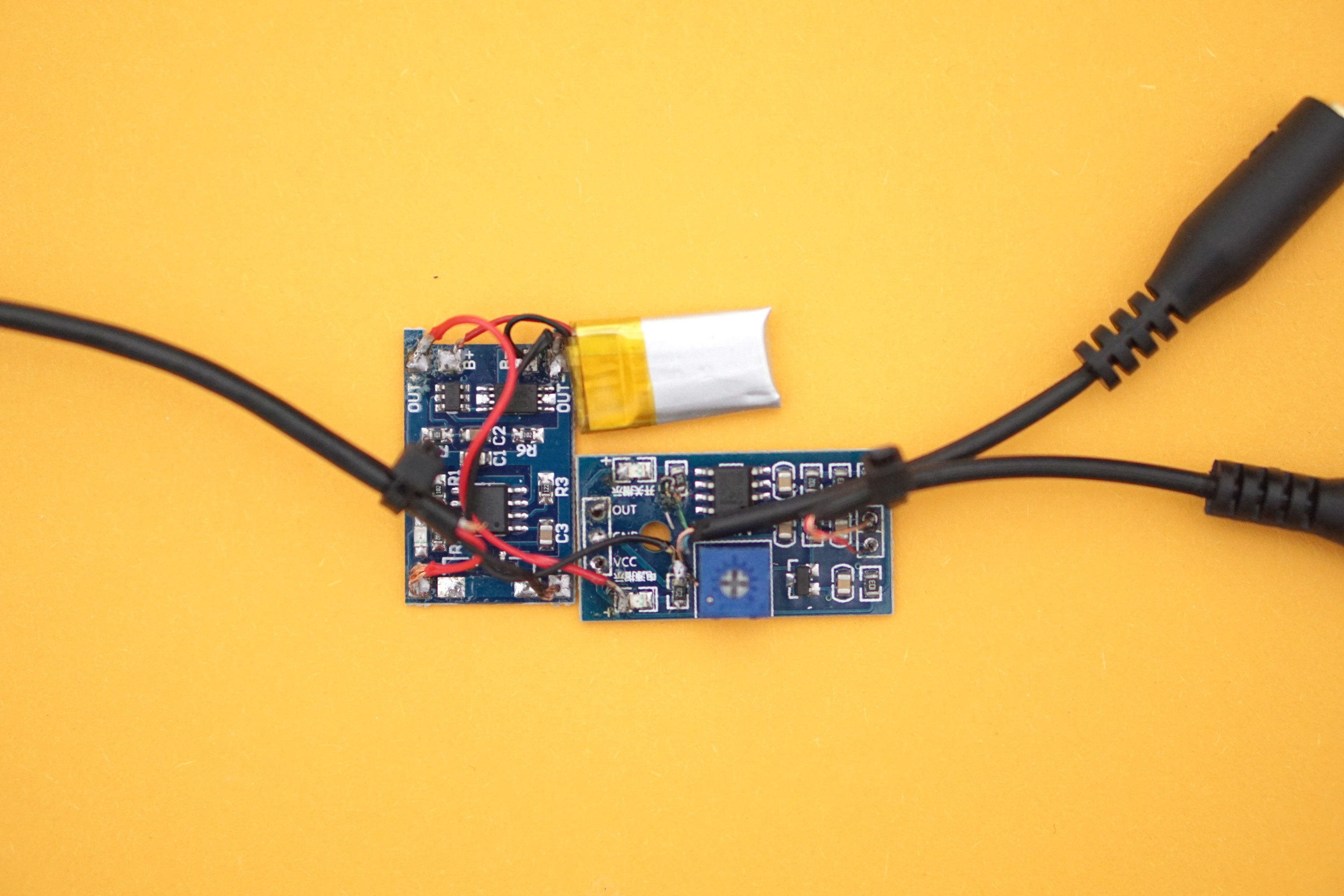
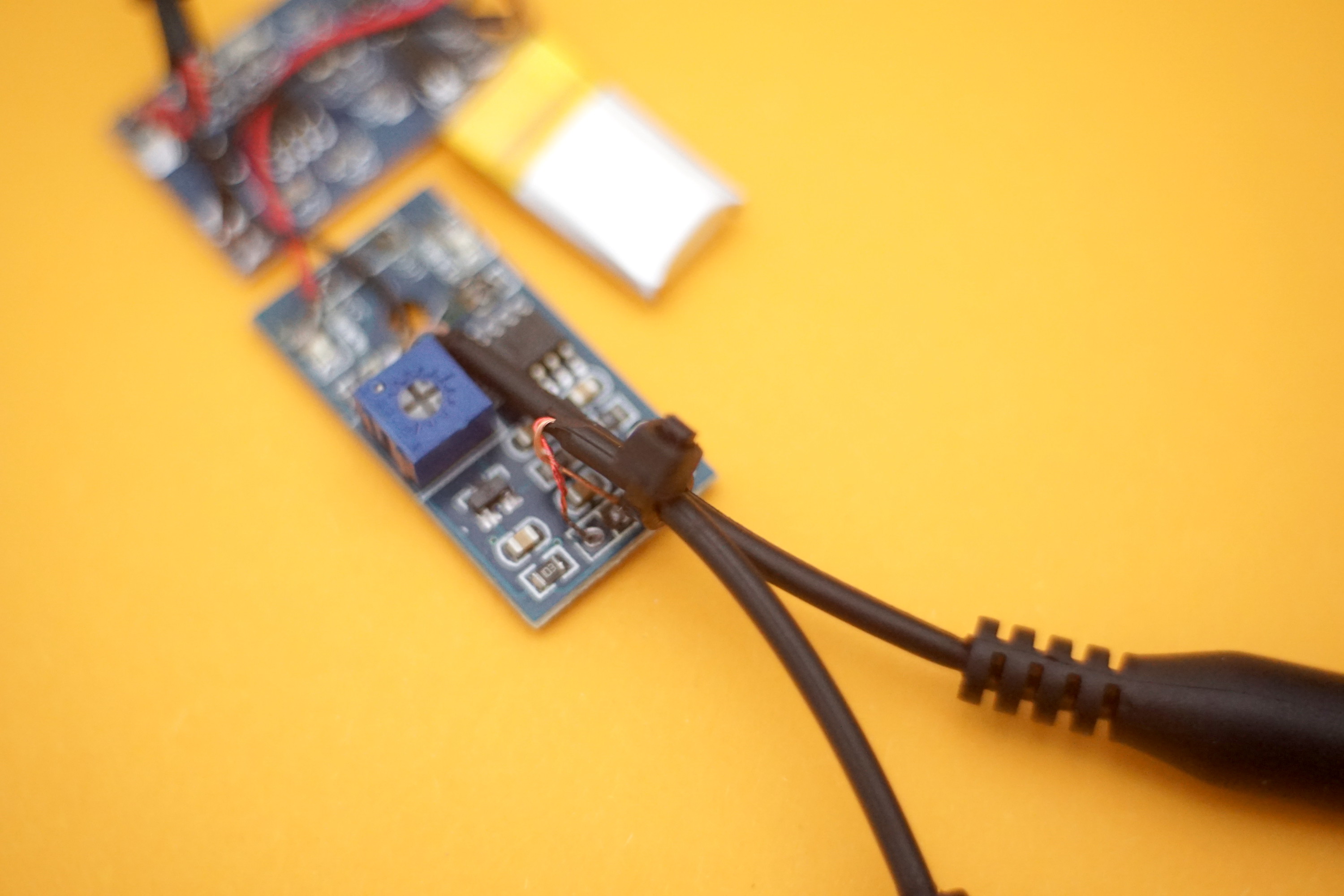
- Put your assembly in the Project Box;
- Make small hole for On/Off switch and glue it (you can skip this and simply leave switch inside the box);
- Tighten Cable Ties around USB and 3.5mm connectors cables;
- Cut excessive Cable Ties ends;
- Place cables inside the Project Box;
- Close Project Box, glue is not needed. On this step, permanent device is ready to use.
Tools for this step: Hot Glue Gun and Refills, Side Cutters, Protective Gloves.
Prepare Some Additional Parts
Now, when your device is completed, additionally you'll need:
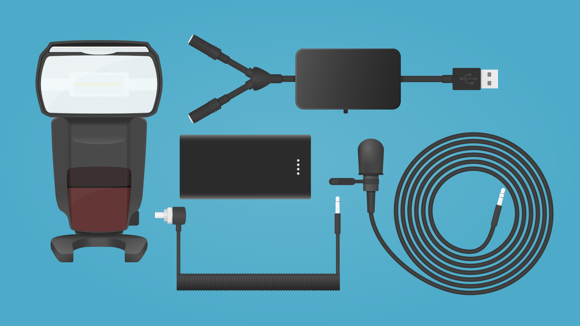
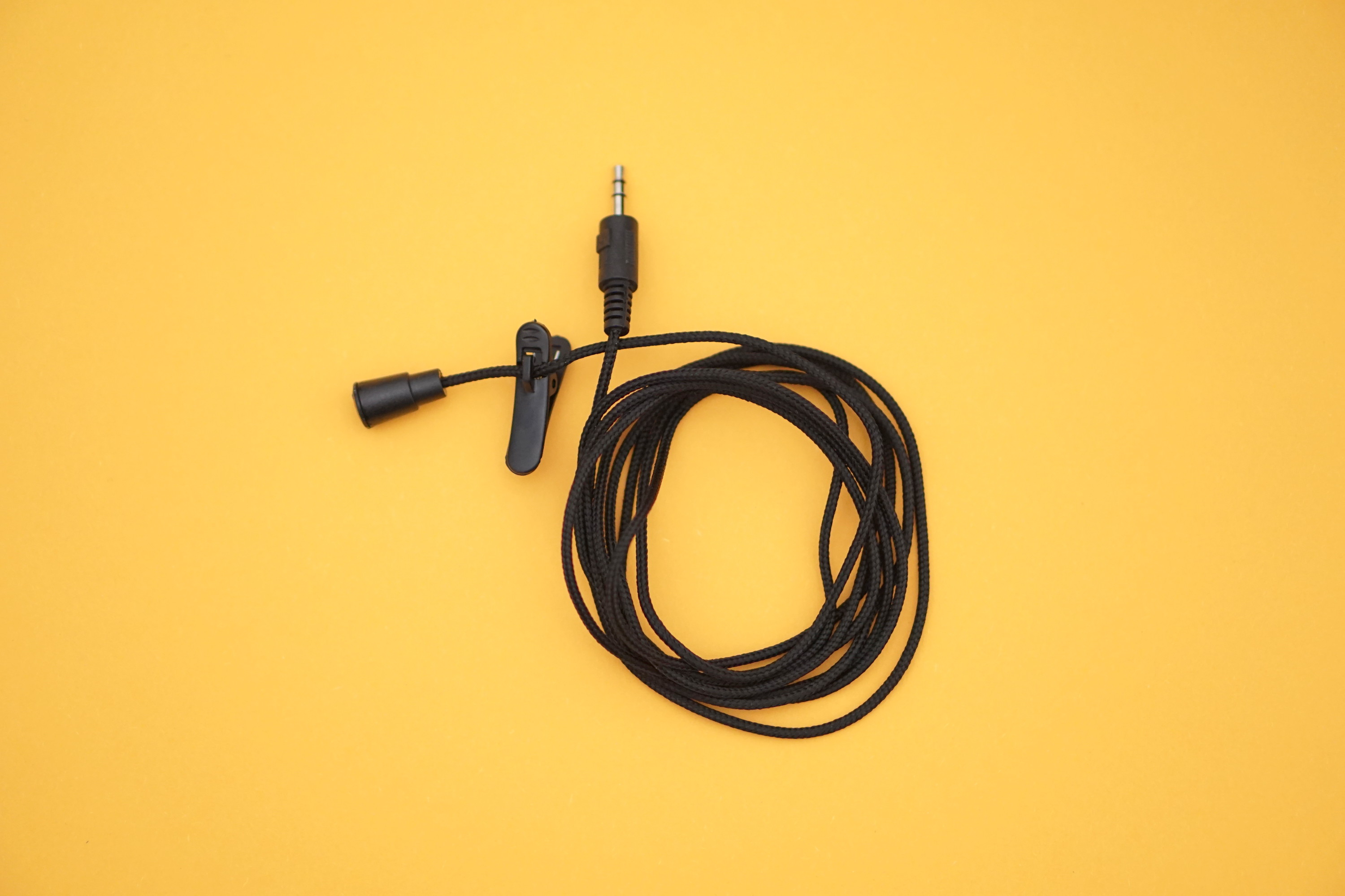
- External Mic with 3.5mm connector (You can use Lav Mic);
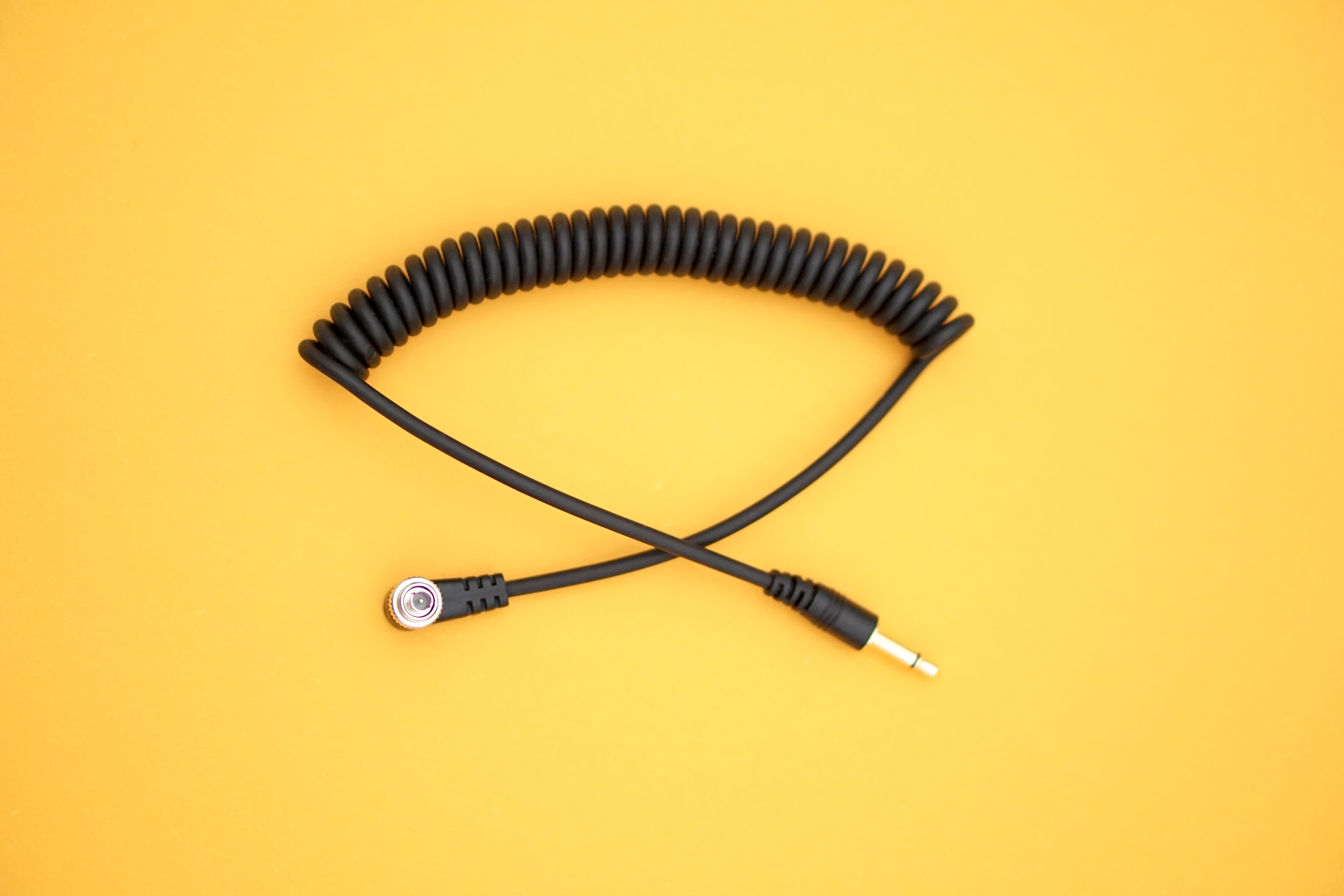
- Flash (PC) Sync Cable with 3.5mm connector or Hot Shoe connector (depending on which type of connection has your camera flash);
- Power source to charge your “Sound Camera Flash Trigger” (For example Power Bank or Wall Charger).
SetUp Camera Flash
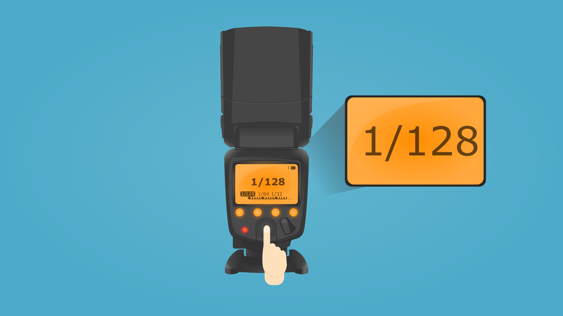
Put your camera Flash power as low as possible, in most cases this is 1/128 sec.
Put Camera Flash Inside the Pumpkin
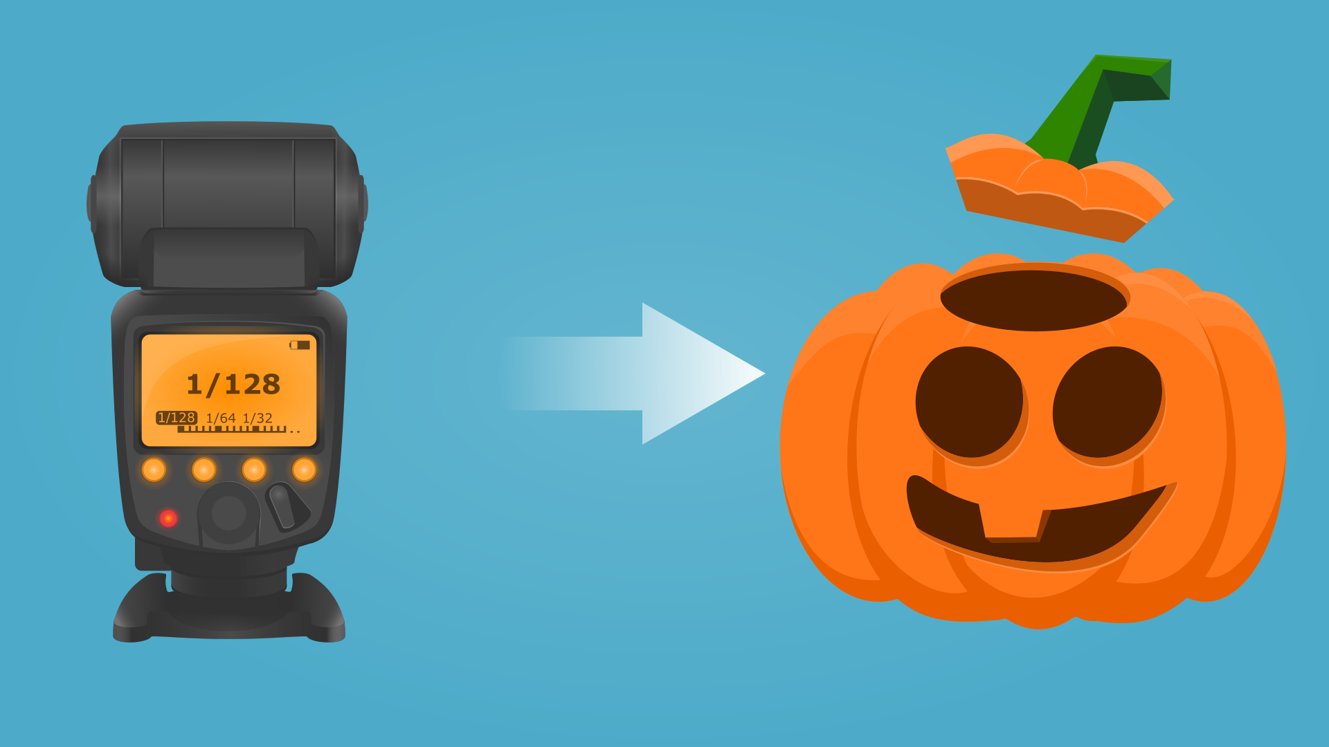
Put camera flash pointing head to the back wall. In this case you’ll get orange light without any gels or color filters.
Pumpkin size (at least): 25cm/10in(H)x35cm/14in(D).
Play Music
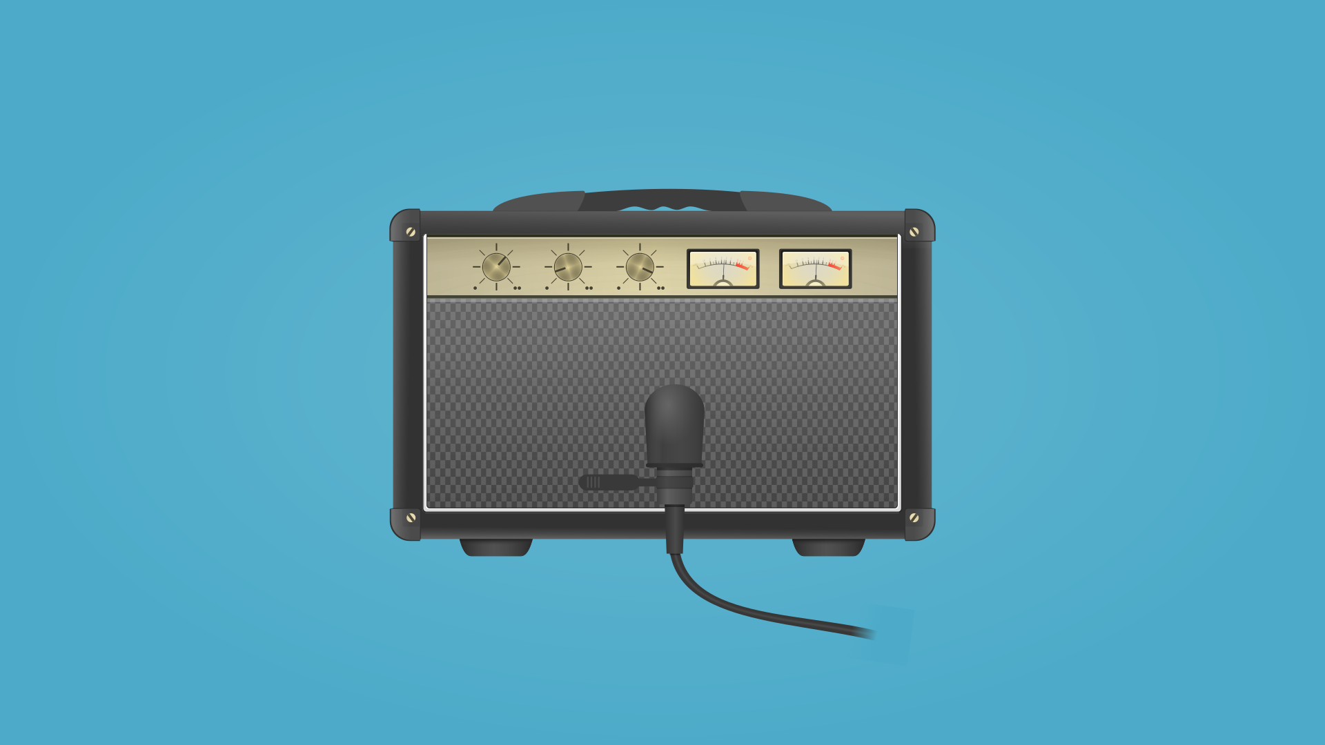
Place microphone close to your sound source, for example Bluetooth speaker.
Enjoy Result

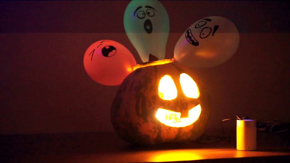

- Turn Off ambient light;
- Play your favorite song with a lots of clear beats;
- Be happy.