Song Synchronized Christmas Lights
by MSofeska in Circuits > Arduino
1047 Views, 1 Favorites, 0 Comments
Song Synchronized Christmas Lights
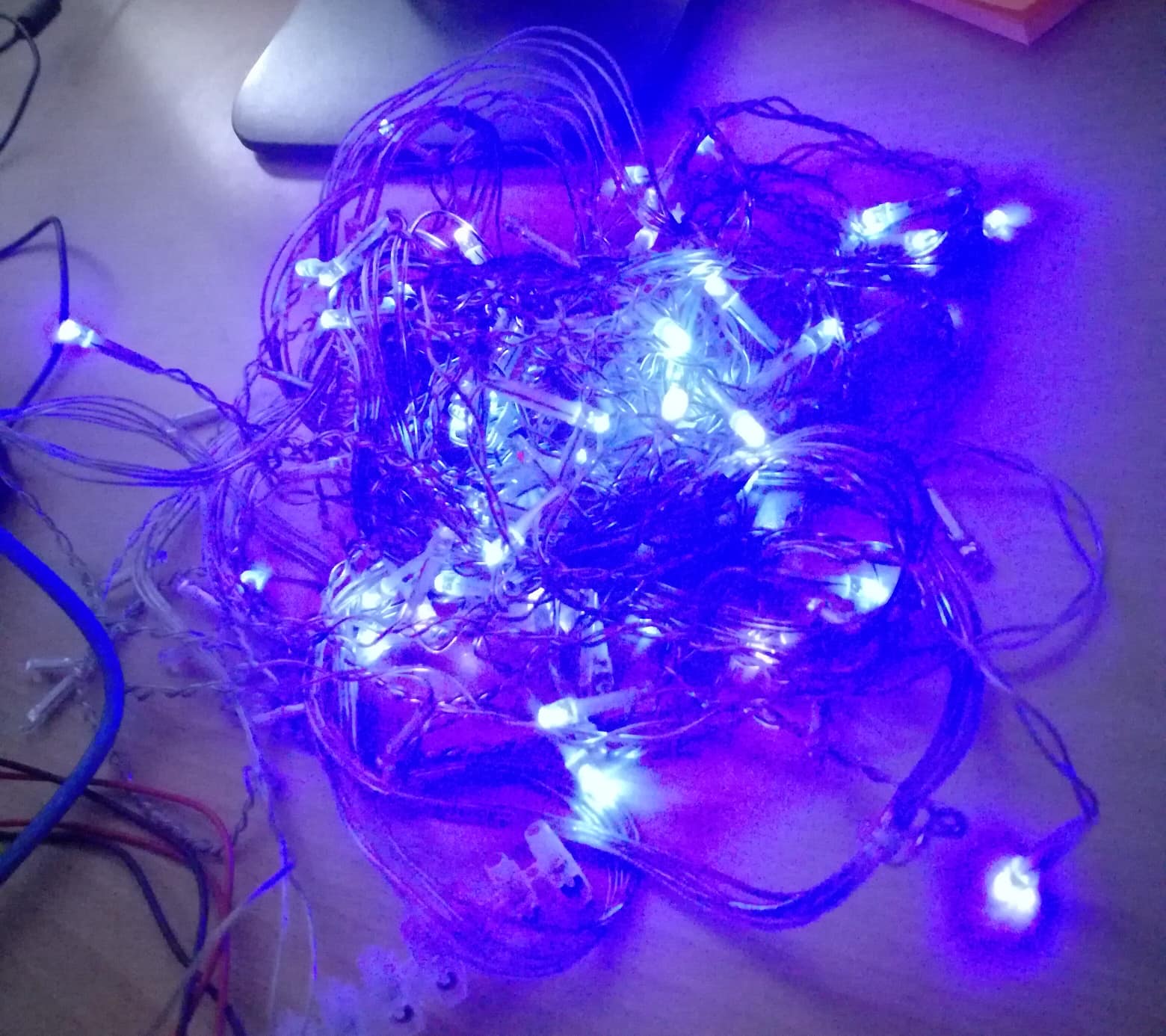
These is a very interesting project, that doesn't take much skills to do it and I am convinced that anyone can! Once you've seen the steps needed, I encourage you to try and make this, not because it's something you can, but because it's something that's really fun to do and when Christmas comes you'll have your own homemade Christmas lights. Have fun guys, and I really hope you'll enjoy doing this.
You can synchronized your lights with any song you want with just a simple change of the code. We've chosen the Jingle Bells song.
Before you start I recommend to buy all the materials needed, that are listed below.
Hover over the images to get more information!
Total time for completing: 4 - 5 hours
Things you'll need:
Materials:
- mini push button, see here
- LED, see here
- 8-ohm speaker, see here
- 150 ohm resistor, see here
- 100 ohm resistor , see here
- 10 K ohm resistor, see here
- Male to Male jumper pins see here
Connecting the LEDs
Things you'll need for this step:
- Arduino
- Breadboard
- 150 ohm resistorLED
- Jumper Pins (x3)
In order to supply power to the breadboard you will need:
- Attach a jumper pin from the Arduino GND to the negative line (the blue one) on the breadboard.
- Attach a jumper pin from the Arduino 5V to the positive line (the red one) on the breadboard.
Connecting the LEDs:
- Set one of the LEDs to the breadboard (one leg to either side of the board)
- Pay attention to the legs of the LED, the shorter one is negative, while the longer is positive.
- Connect the resistor with the short leg of the LED and the negative (blue) line. Make sure the resistor and LED leg are on the same row.
- Connect the other leg of the LED to pin number 13 on the Arduino with a jumper pin.
Make the LED Blink
You will need:
- USB cable
Download and Install Arduino Software, you can find it here
- Set up the programme
- Write a code to make the LED blink
- Make sure that Tools -> Serial Port is set to /dev/tty.usbmodem or /dev/cu.usbmodem as we are connected with our USB cable, not with bluetooth
- When writing the code remember that the LED is connected to pin 13 on Arduino, the LOW means the LED is switch off, HIGH meand the LED is on!
If connected properly the LED should be blinking on and of. See a tutorial here
Downloads
Connecting the Speaker
Things you will need:
- 100 ohm resistor
- 8 ohm speaker
- Jumper pin
Connecting the speaker tutorial ca be found here
- Connect the speaker in a way that one of the cables is connected to the negative (blue) line of the breadboard.
- The other cable from the speaker connect to any free pin on the board, but make sure that it is not in the same line with the LED.
- Put the resistor on the same line as the speaker.
- Connect the jumper pin from the speaker to the Arduino on pin 9.
Setting up the code for the speaker:
- You can copy/paste the code for playing a melody from the Arduino Official web site, and make some changes in order to play the Jingle Bells melody. (code can be found here
- Upload the code
Downloads
Synchronizing the LED With the Sound
Things you will need:
USB cable
Code for this step:
<pre>// TONES  ========================================== // Start by defining the relationship between<br>//       note, period, &  frequency.
#define  C     2100
#define  D     1870
#define  E     1670
#define  f     1580    // Does not seem to like capital F
#define  G     1400
// Define a special note, 'R', to represent a rest
#define  R     0
// SETUP ============================================
// Set up speaker on a PWM pin (digital 9, 10 or 11)
int speakerOut = 9;
int led = 13;
// Do we want debugging on serial out? 1 for yes, 0 for no
int DEBUG = 1;
void setup() {
   pinMode(speakerOut, OUTPUT);
   pinMode(led, OUTPUT);
   if (DEBUG) {
     Serial.begin(9600); // Set serial out if we want debugging
   }
}
// MELODY and TIMING  =======================================
//  melody[] is an array of notes, accompanied by beats[],
//  which sets each note's relative length (higher #, longer note)
int melody[] = {E, E, E,R,
E, E, E,R,
E, G, C, D, E, R,
f, f, f,f, f, E, E,E, E, D ,D,E, D, R, G ,R,
E, E, E,R,
E, E, E,R,
E, G, C, D, E, R,
f, f, f,f, f, E, E, E,  G,G, f, D, C,R };
int MAX_COUNT = sizeof(melody) / 2; // Melody length, for looping.
// Set overall tempo
long tempo = 10000;
// Set length of pause between notes
int pause = 1000;
// Loop variable to increase Rest length
int rest_count = 100; //<-BLETCHEROUS HACK; See NOTES
// Initialize core variables
int tone_ = 0;
int beat = 0;
long duration  = 0;
// PLAY TONE  ==============================================
// Pulse the speaker to play a tone for a particular duration
void playTone() {
   long elapsed_time = 0;
   if (tone_ > 0) { // if this isn't a Rest beat, while the tone has
     //  played less long than 'duration', pulse speaker HIGH and LOW
     digitalWrite(led, HIGH);
     while (elapsed_time < duration) {
       digitalWrite(speakerOut,HIGH);
       delayMicroseconds(tone_ / 2);
       // DOWN
       digitalWrite(speakerOut, LOW);
       delayMicroseconds(tone_ / 2);
       // Keep track of how long we pulsed
       elapsed_time += (tone_);
     }
   digitalWrite(led, LOW);
   }
   else { // Rest beat; loop times delay
     for (int j = 0; j < rest_count; j++) { // See NOTE on rest_count
       delayMicroseconds(duration);
     }
   }
}
// LET THE WILD RUMPUS BEGIN =============================
void loop() {
  for (int i=0; i < MAX_COUNT;i++){
tone_ = melody[i];
beat = 50;
duration = beat * tempo; // Set up timing
    playTone();
    // A pause between notes...
    delayMicroseconds(pause);
  }
}
Set Up the Button
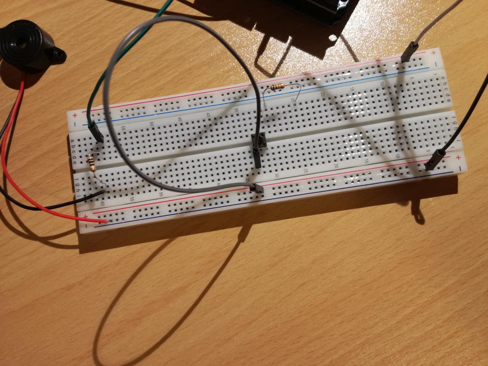
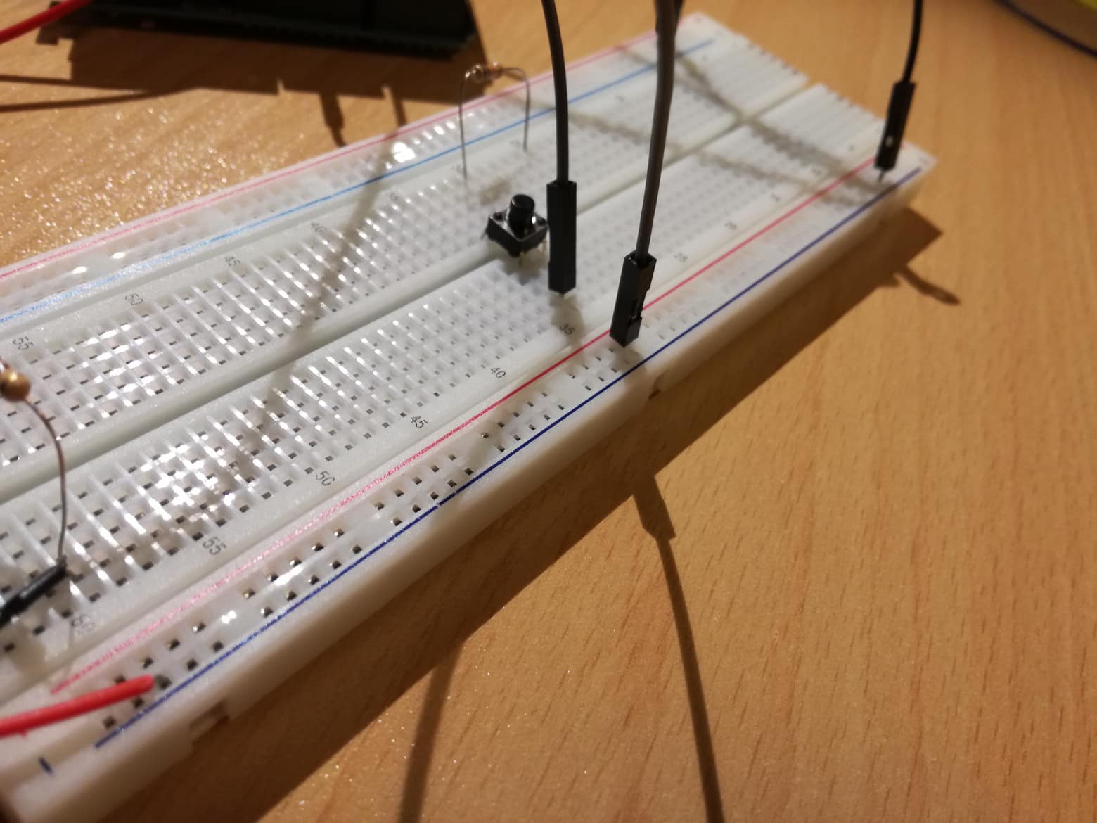
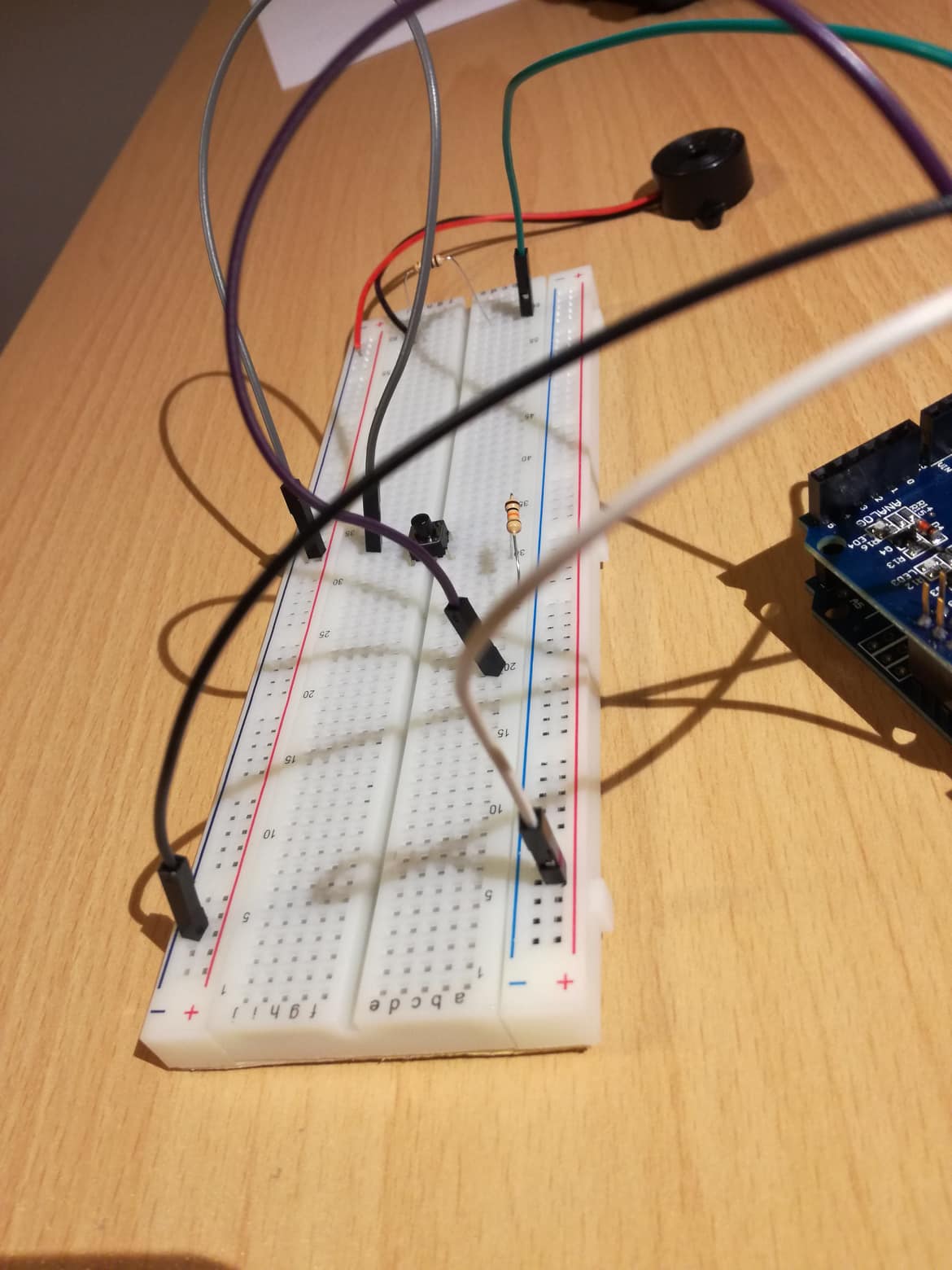
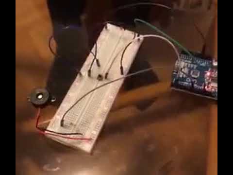
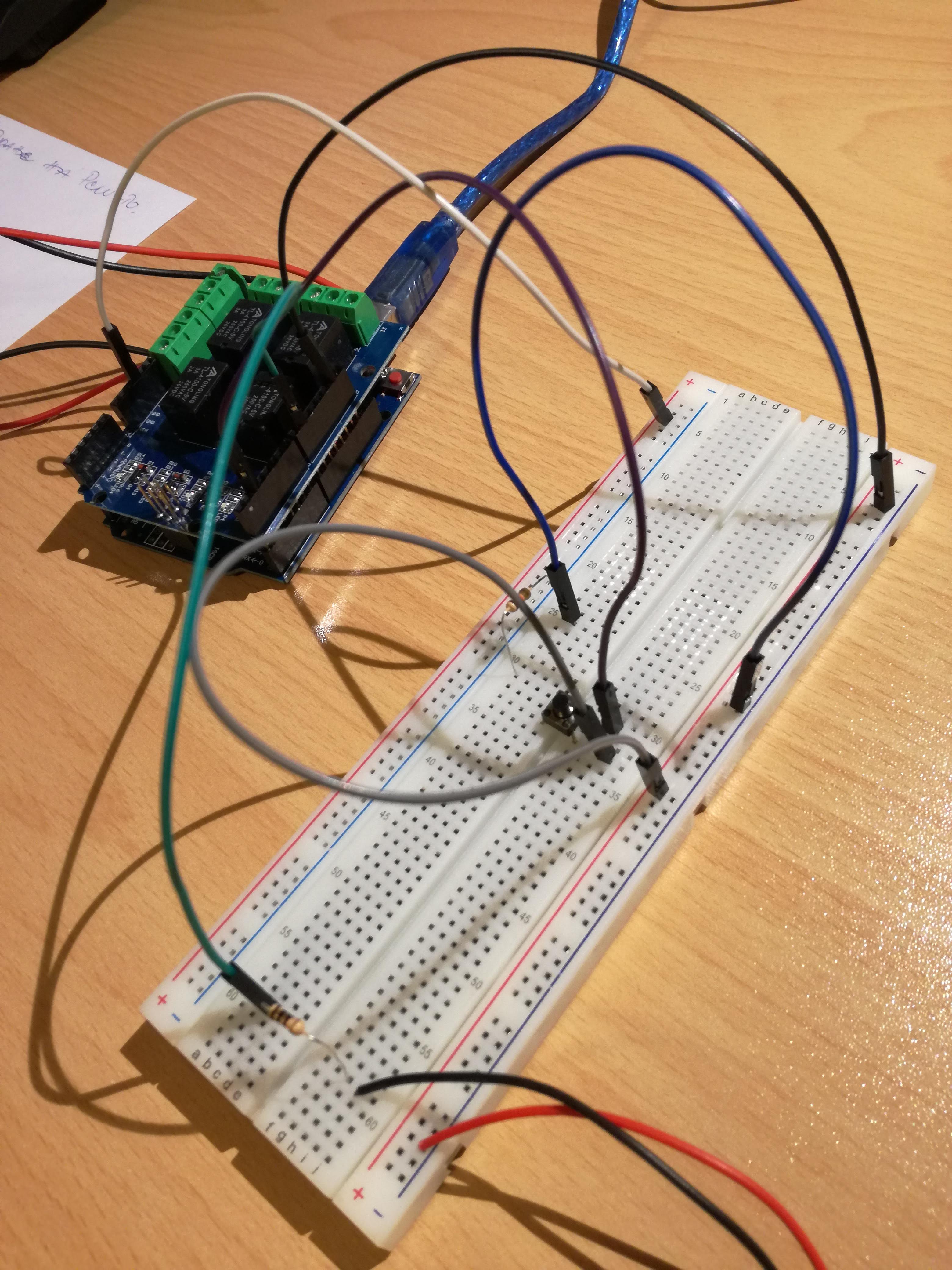
Things you will need:
- mini push button
- 10 K ohm resistor
- jumper pins(x3)
- USB cable
Connecting the button
- Place the button on the centre line of the breadboard
- Connect one of the legs to the red positive line using a jumper pin
- Connect the other side of the resistor to the blue negative line
- On the other side of the button, connect the leg of the jumper pin on the the same row as the resistor to pin 2 on the Arduino
- Attach the USB cable to the Arduino
- Upload the file
Downloads
Setting Up the Lights
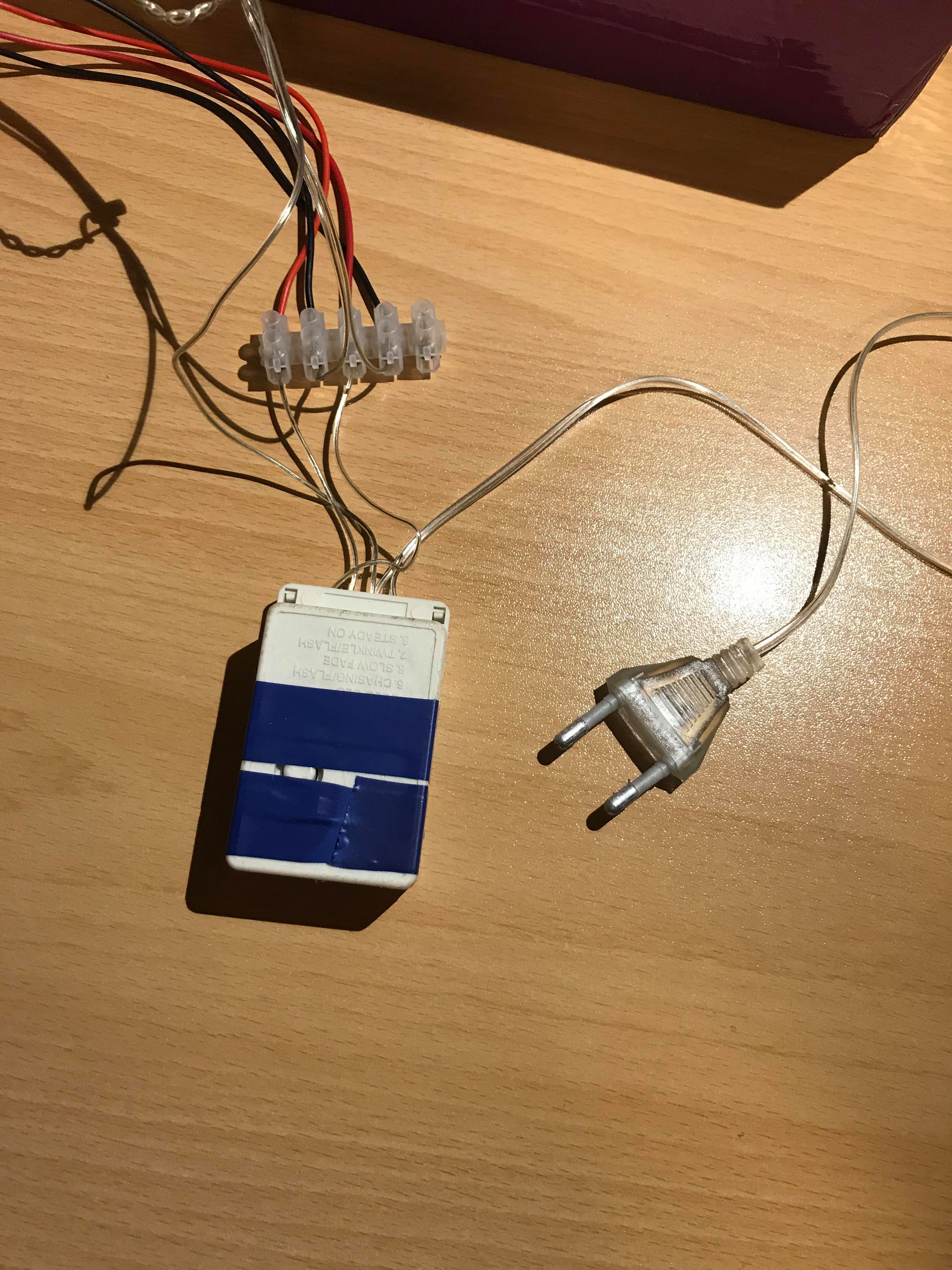
Things you will need:
- Christmas lights
- Terminal Block
The connection of the lights might be different, because it depends on the lights.
- You will need to determine which cable gives the power supply for the lights;
- Next, you will need to determine the GND cable that goes directly to the chip that comes with the lights ( I didn't get rid of it, because my set of lights is too large and I need the resistor that comes with the lights);
- The other two go from the chip to the terminal block and back from the lights to the terminal block;
Connecting With Relay Shield
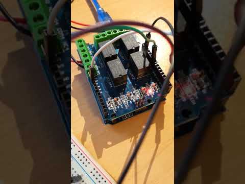
You will need:
- Relay Shield
- In order to connect the Christmas lights we need 4 Channel Relay Shield, because we want to connect high power lights with low power Arduino;
- Make sure that the Relay Shield does not touch the USB port of Arduino, put some electrical tape around it, or something to separate this.
- Disconnect the pins from Arduino and place the Relay Shield
- Connect the Relay good, and if it doesn't fit good put a rubber band around them both
- Put the jumper pins on the Relay accordingly
- Relay pins : Pin 7 = Relay 1, Pin 6 = Relay 2, Pin 5 = Really 3 , Pin 4 = Relay 4
- Our pin connections: Pin 9 - Speaker, 5V Pin - Positive, GND Pin - Negative, Pin 2 - Button
See the Relay Shield connection, here
Testing Relay Code:
#define  C     2100<br>#define  D     1870
#define  E     1670
#define  f     1580    // Does not seem to like capital F
#define  G     1400
// Define a special note, 'R', to represent a rest
#define  R     0
// SETUP ============================================
// Set up speaker on a PWM pin (digital 9, 10 or 11)
int speakerOut = 9;
int green = 4;
int red = 7;
int buttonPin = 2;

void setup() {
 	pinMode(speakerOut, OUTPUT);

	pinMode(green, OUTPUT);

 	pinMode(red, OUTPUT);

	pinMode(buttonPin, INPUT);

	digitalWrite(green, LOW);

}
Connecting the Lights With Relay Shield
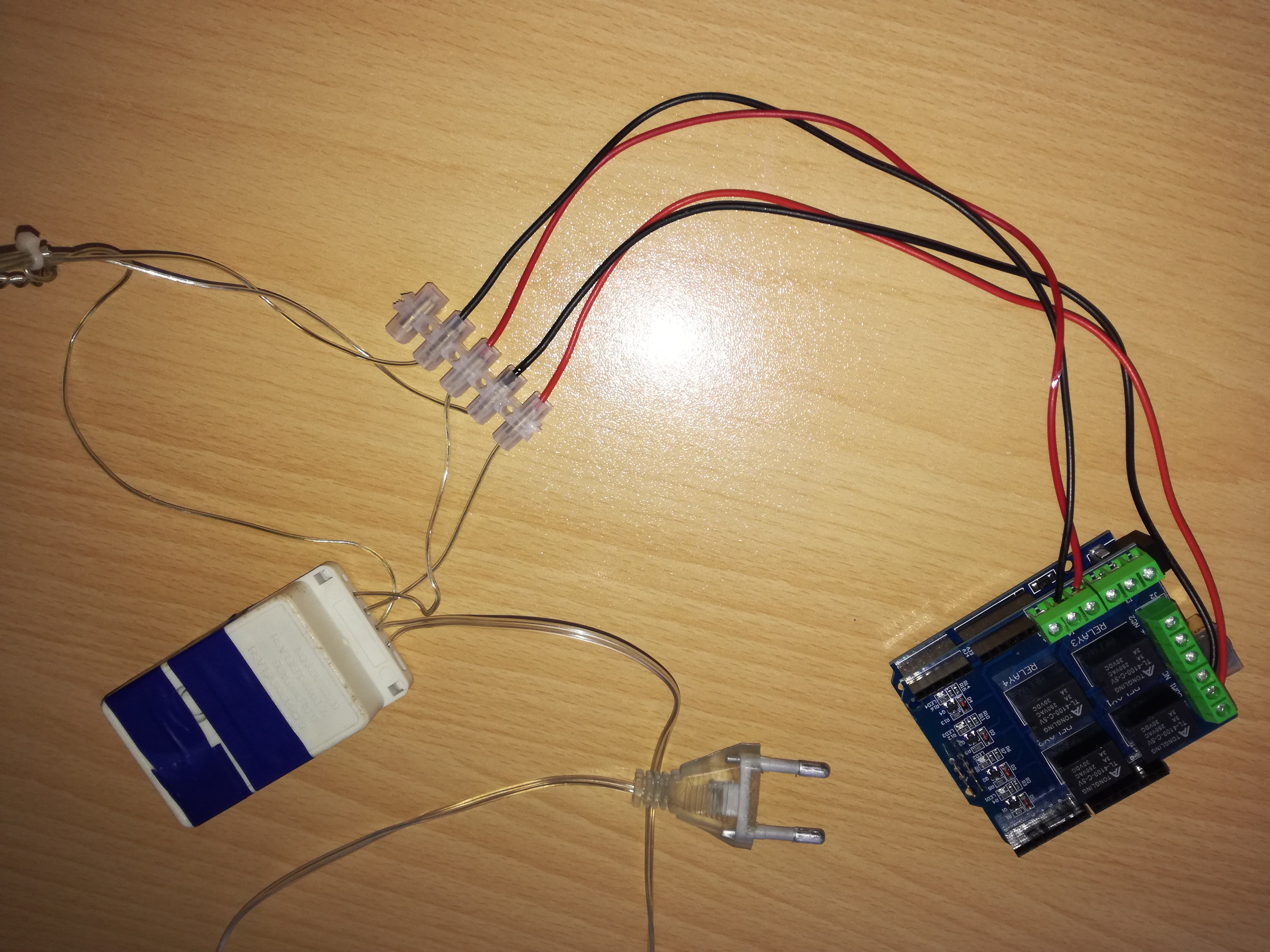
After the set up of the Relay it's time to set up the lights to it
We will be using pin 4 and pin 7, to the corresponding relays 4 and 1, beacuse we have only two sets of lights to switch on and off.
- Do not connect the lights to the mains;
- The Relay have 3 connections:
- Relay switch is default open;
- Common - connected if either open or closed;
- Relay switch id default closed connection;
- Unscrew your first set of light cables from the terminal block (making sure it is not the ground cable)
- Screw in one end to common relay point
- Screw end the other end to the open relay pointRepeat for your other light cable (again making sure it is not the ground cable) in to the other set relayKeep the ground cable connected with the terminal block.
Checkout the Finished Product


Things you might will need:
- If you don't want to be using your laptop/ PC for power supply of the Arduino, you can buy an adapter;
CONGRATULATIONS you've made it!