Social Distancer 3000
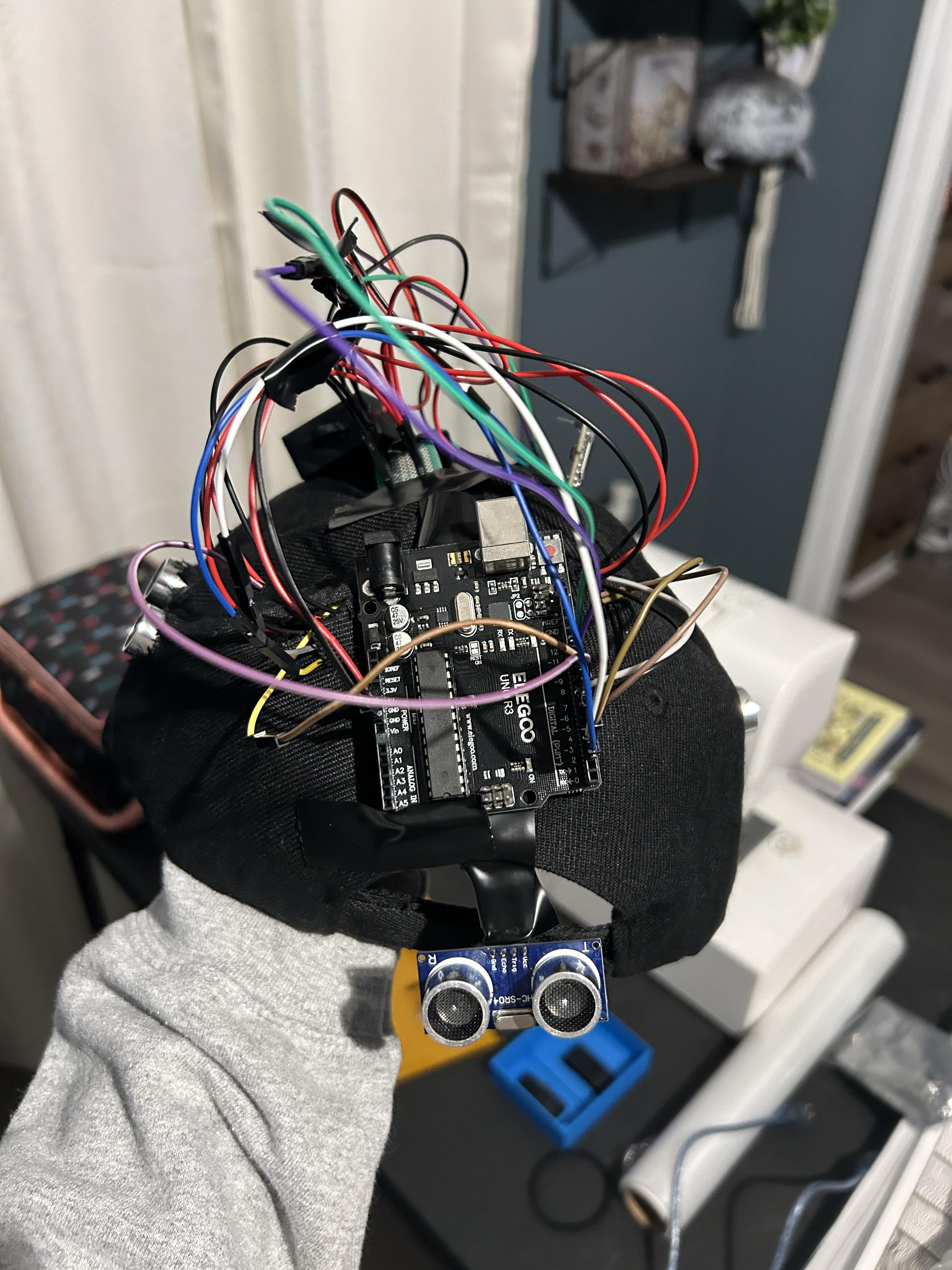
This guide will walk you through creating a fun, sensor-based hat that plays audio tracks (of insults) when someone enters your personal space. The Social Distancer 3000 uses ultrasonic sensors and a DFPlayer Mini to detect proximity and play audio files. The sensors are embedded in a ball cap, with one facing forward, one backward, and one on each side.
Supplies
Materials Needed
- Electronics
- Arduino Uno R3 (or compatible microcontroller) - I use the Elegoo Uno R3 because it's cheaper.
- 4 x HCSR04 Ultrasonic Sensors - can be found here.
- DFPlayer Mini MP3 Player Module - can be found here.
- MicroSD Card (formatted with audio files) - can be found here.
- 8Ω Speaker - can be found here.
- 2 x 1kΩ resistors - can be found here.
- Power source (USB power bank or 9V battery with connector)
- 14 x Dupont header pins - can be found here.
- Perfboard - can be found here.
- A LOT of jumper cables (female to male, male to male)
- 2 x AA batteries with holder and DC connector
- Hat
- A hat of your choice (I used a ball cap, but you may want one with consistent coverage around the head)
- Tools
- Scissors for creating holes in the cap
- Soldering kit (to create a power bus - you will have multiple connections needing the 5V and GND pins)
- Hot glue gun or adhesive for mounting components
- Multimeter - to check for continuity of soldering
- Software
- Arduino IDE (downloadable from Arduino.cc)
- Required libraries:
- DFRobotDFPlayer_Mini (for audio control)
Testing the Components
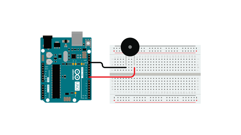
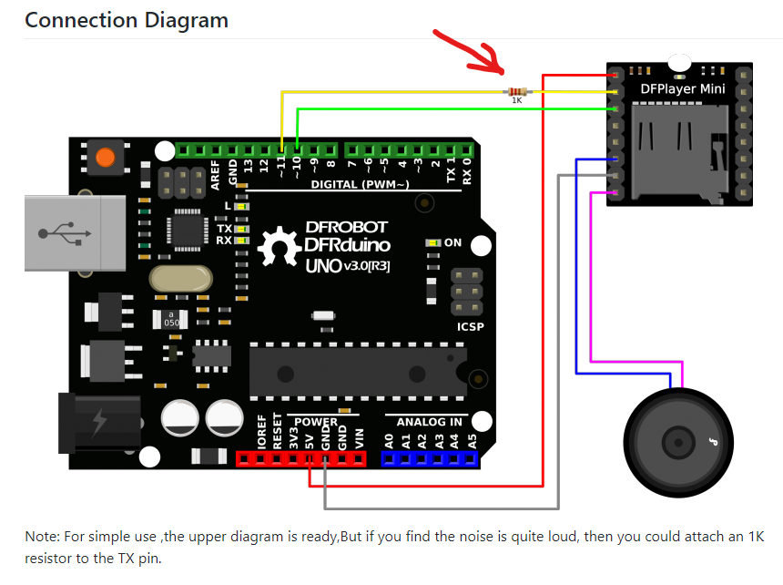
Before making any connections, you will want to test your DFPlayer Mini, speaker, SR04 sensors, and your wires/jumper cables to make sure they are in working condition.
- Test each SR04 sensor separately using the SR04 example sketch on Arduino. It can be accessed here.
- Once all sensors are in confirmed working order, you will want to test your speaker. Test the speaker using the toneMelody example sketch on Arduino. It can be accessed here.
- Now that you have a working speaker, it's time to test your DFPlayer Mini to see if you are able to play downloaded mp3 tracks. For this example, you will want to download 3 mp3 files of your choice and create a folder on your micro SD card, which you will name "mp3".
Once your folder is created, you will place the three mp3 files into the folder and rename them as 0001, 0002, and 0003. Please ensure that the micro SD card is formatted to FAT32.
- Once your mp3 files are uploaded and formatted to the micro SD card, you will place the SD card into the DFPlayer Mini. From here, we will test the DFPlayer Mini for functionality via the DFRobot_DFPlayer example sketch on Arduino. It can be accessed here.
- Next, you will need to make a power bus using the perfboard and Dupont pin headers. Cut out a section of perfboard that is 2 x 7 holes (this means you will have two rows of seven holes). Place two strips of seven pin headers through the holes and solder the bottom. Ensure that your solder connects all pins to each other. When you use your multimeter to check for continuity, you should have a solid connection for each pin. Here is a video example of how to connect the pins to the perfboard. One row will serve as the positive side, and the other as the negative.
When all parts pass the testing phase, it's time to move on to combining codes and pieces.
Mix It All Together
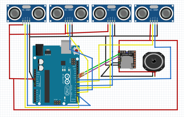
This project took a total of 4 different iterations - taking bits and pieces from the SR04 and DFPlayer codes while trying to simultaneously find a way to link additional sensors to the player/speaker so they would be able to scan and trigger the speaker at the same time. If you encounter issues, PLEASE make sure you take a step back and test everything all over again. I was stumped on this step for a week and a half - not realizing that I had a bad wire connected to my speaker!
Now that everything is in working order, it is time to COMBINE all the pieces we have!
I realize that the image above may seem very confusing and intimidating, but fear not! It was just basically impossible to create the graph without crossing wires at some point. I did try to make it as comprehensive as possible. For anyone that is still confused, I will provide an explanation that (hopefully) clears it up:
- SR04 sensor 1 (front) - Trig > 2, Echo > 3, VCC > POS side of power bus, GND > GND side of power bus
- SR04 sensor 2 (back) - Trig > 4, Echo > 5, VCC > POS side of power bus, GND > GND side of power bus
- SR04 sensor 3 (left) - Trig > 6, Echo > 7, VCC > POS side of power bus, GND > GND side of power bus
- SR04 sensor 4 (right) - Trig > 8, Echo > 9, VCC > POS side of power bus, GND > GND side of power bus
- DFPlayer Mini - VCC > POS side of power bus, RX > 11 (attach 1k resistor), TX > 10 (attach 1k resistor), SPK 1 > GND side of speaker, GND > GND side of power bus, SPK 2 > POS side of speaker
To avoid additional confusing on the MP3 player, I have also attached a zoomed in photo of it so you can see the pins better!
- Power bus - POS side of power bus > 5V on Arduino, GND side of power bus > GND on Arduino
Downloads
Test the Full Connection
Here is where we will test the entire connection along with the code.
You can access my code here.
You can also access my research and testing notes here for some laughs and an understanding of how the code came about.
Test out the code, wave your hands in front of the sensors and make sure it's working properly!
Once it's working, we can move on to the next step - assembly.
Assembling the Hat
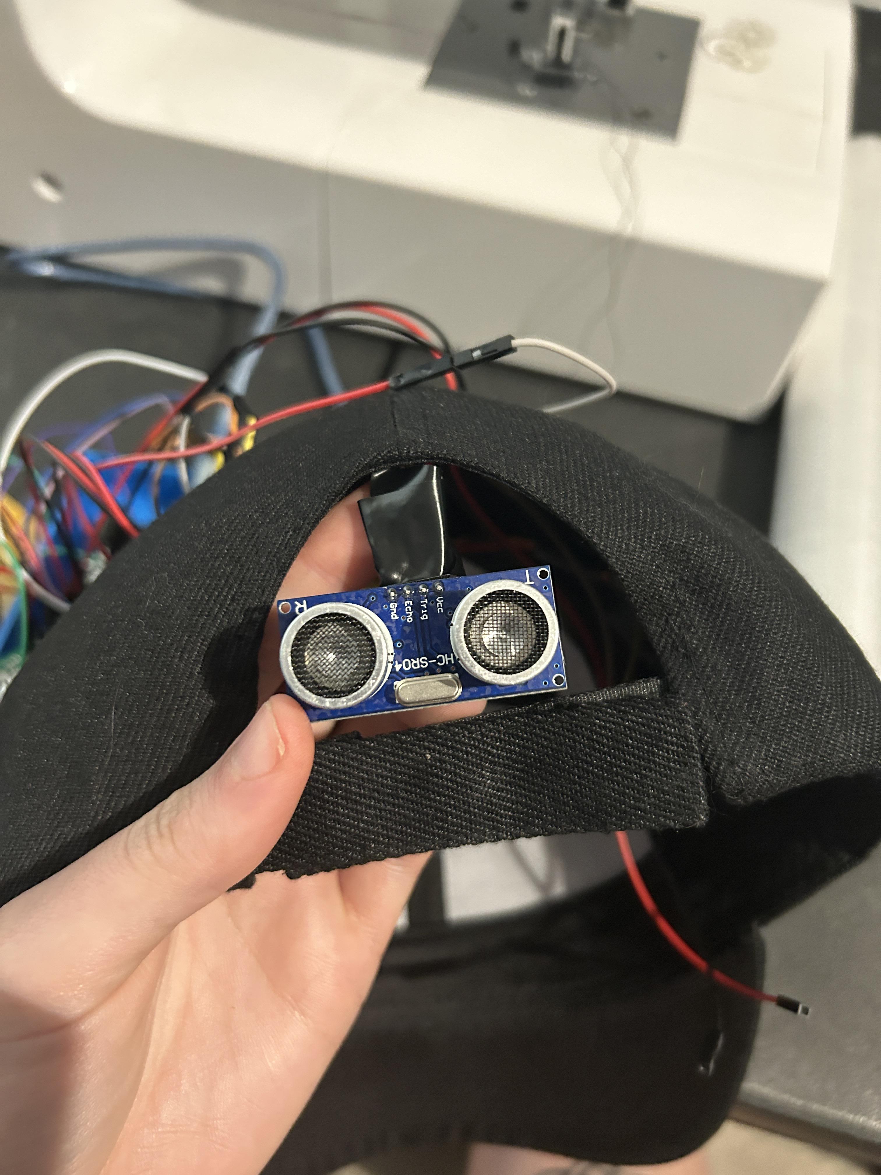
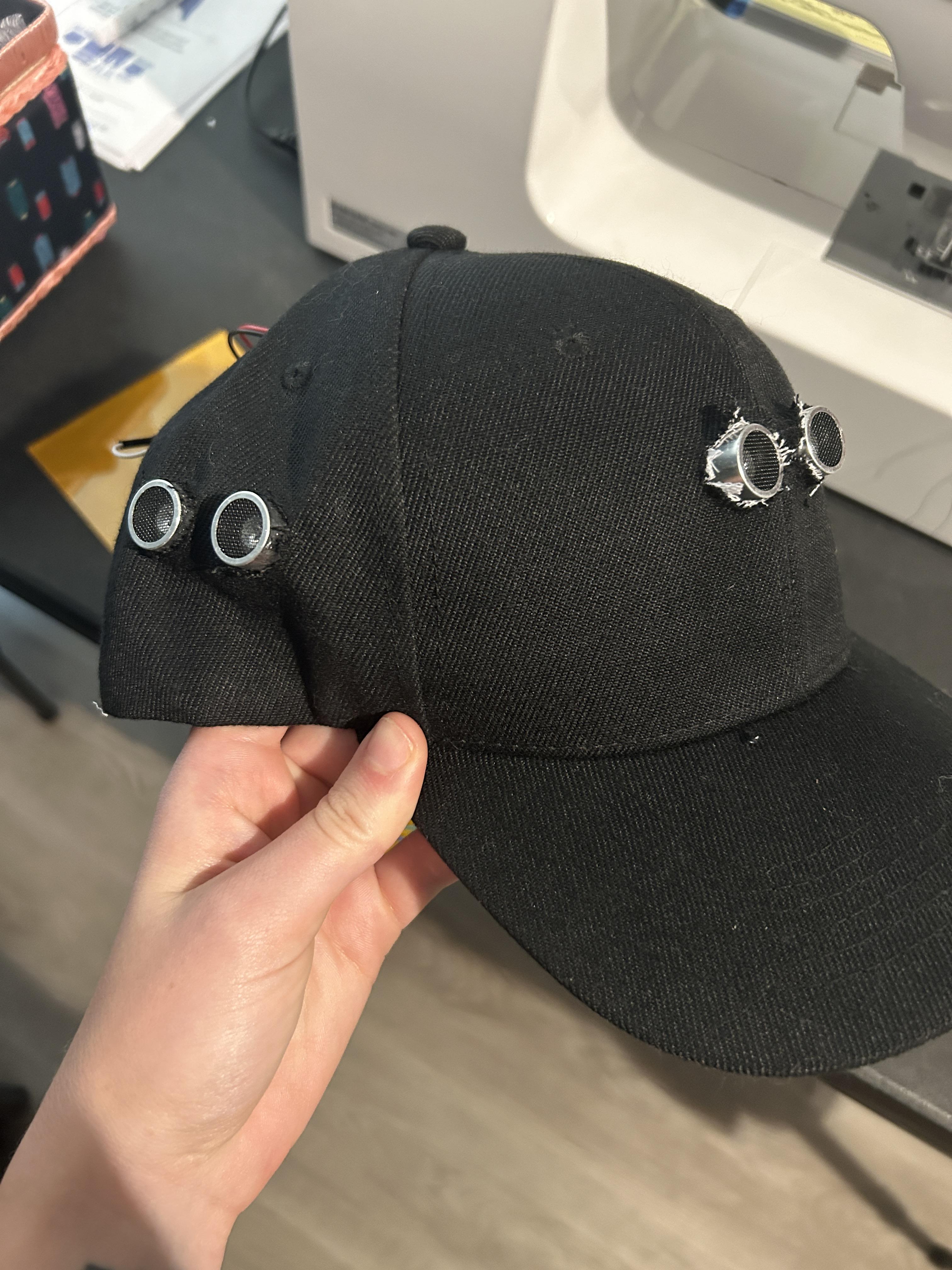
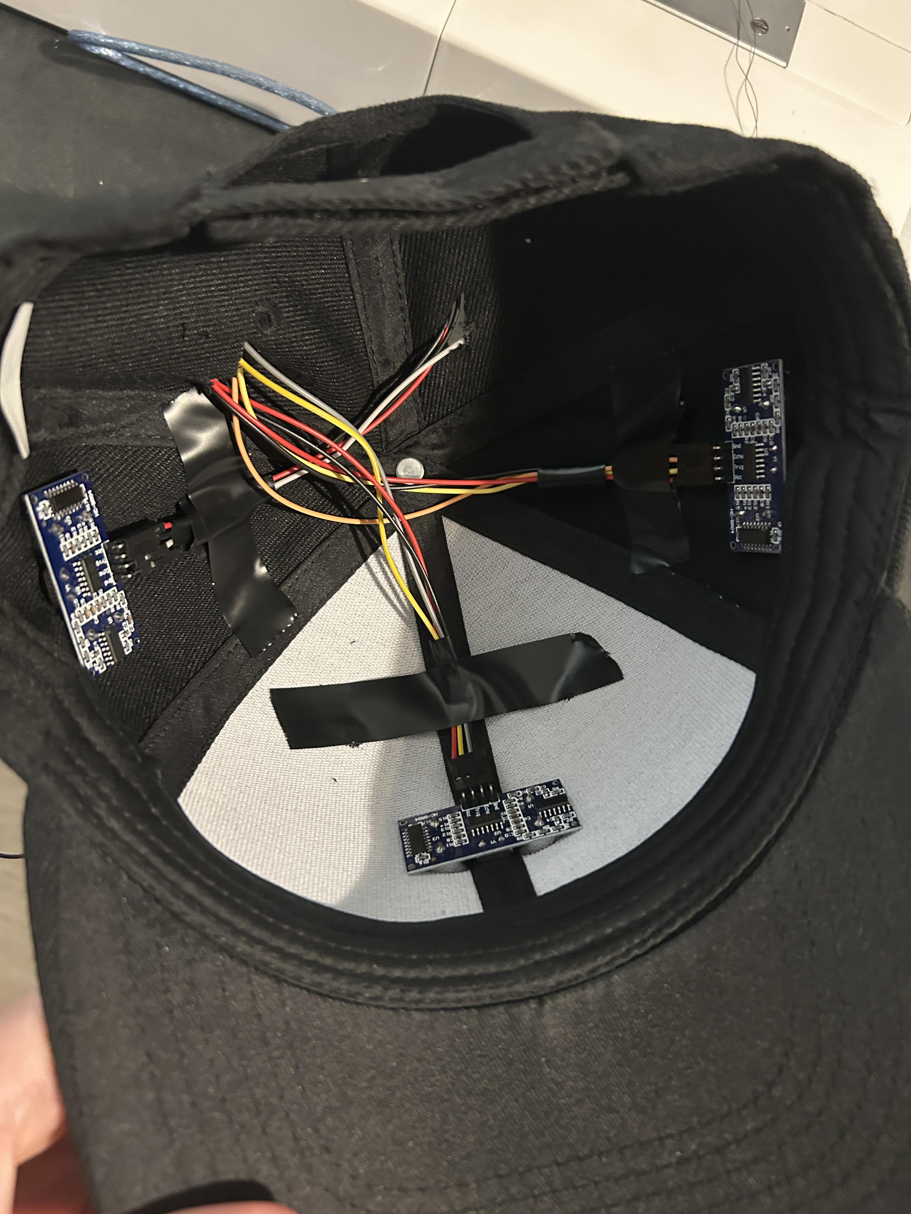
Now to install everything to your hat!
You will need a pair of sharp scissors, and possibly a tool to mark the spots you need to cut. The sensors will be sticking out from the interior of the hat. You will need to cut 4 sets of two holes, roughly the size of the sensors. What helps me is to pinch the fabric and snip. You can continue to cut outwards from the small incision you made to fit your sensors.
Since you may be using a ball cap, you may wonder where the rear sensor will be going. FANTASTIC QUESTION. Wish I would have thought of that before going with a ball cap. Should have went with a boonie cap. However, I accepted my poor decision and had the sensor stick out through the hole in the back. It still gives coverage, it may just look a bit wonky. But this project is JUST FOR FUN! So no worries.
For installing my sensors, I placed them upside down throughout the hat, so all of the wires would collect at the top of the hat rather than wrapping around getting in the way (as shown above).
Finishing Touches
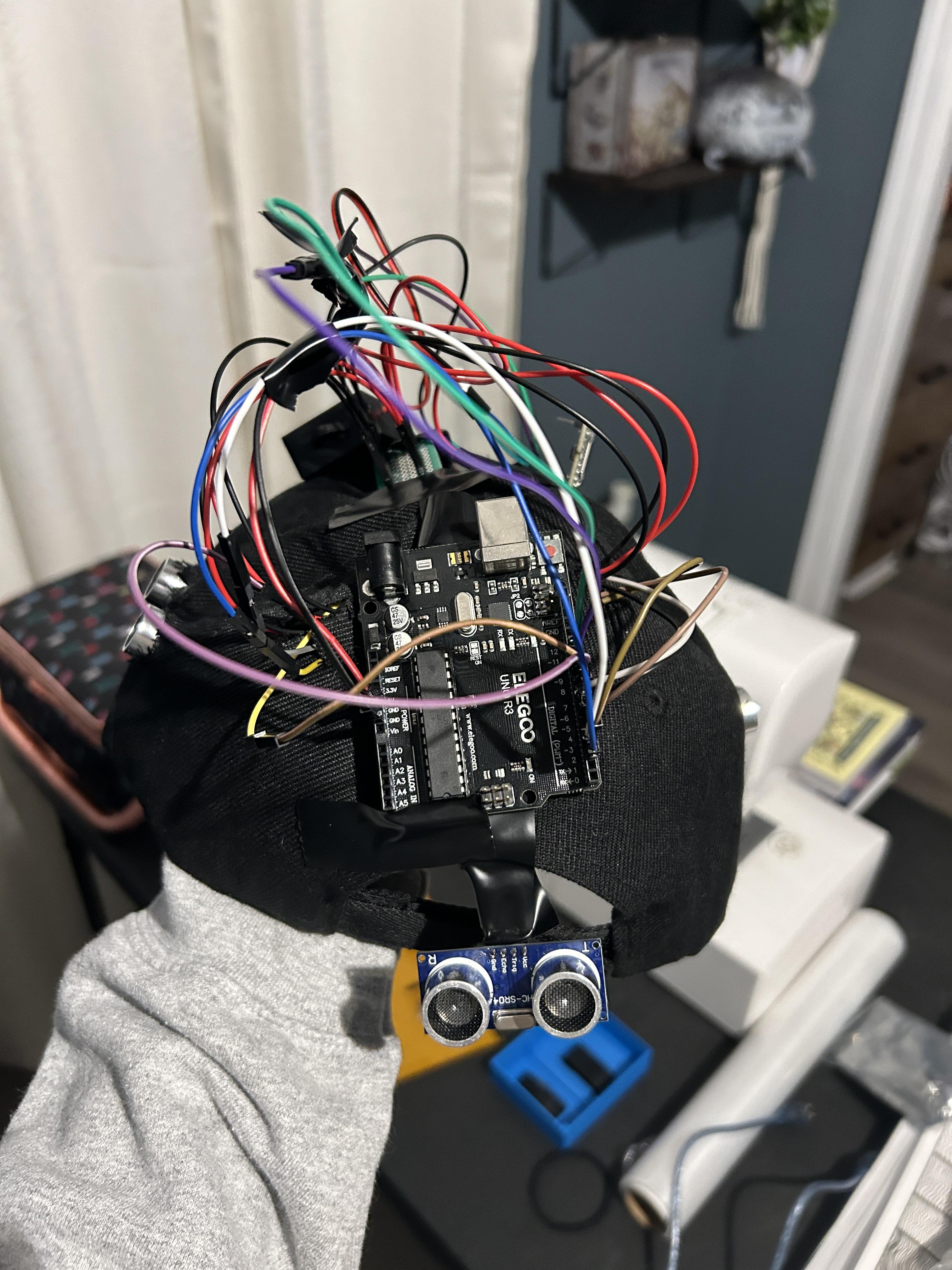
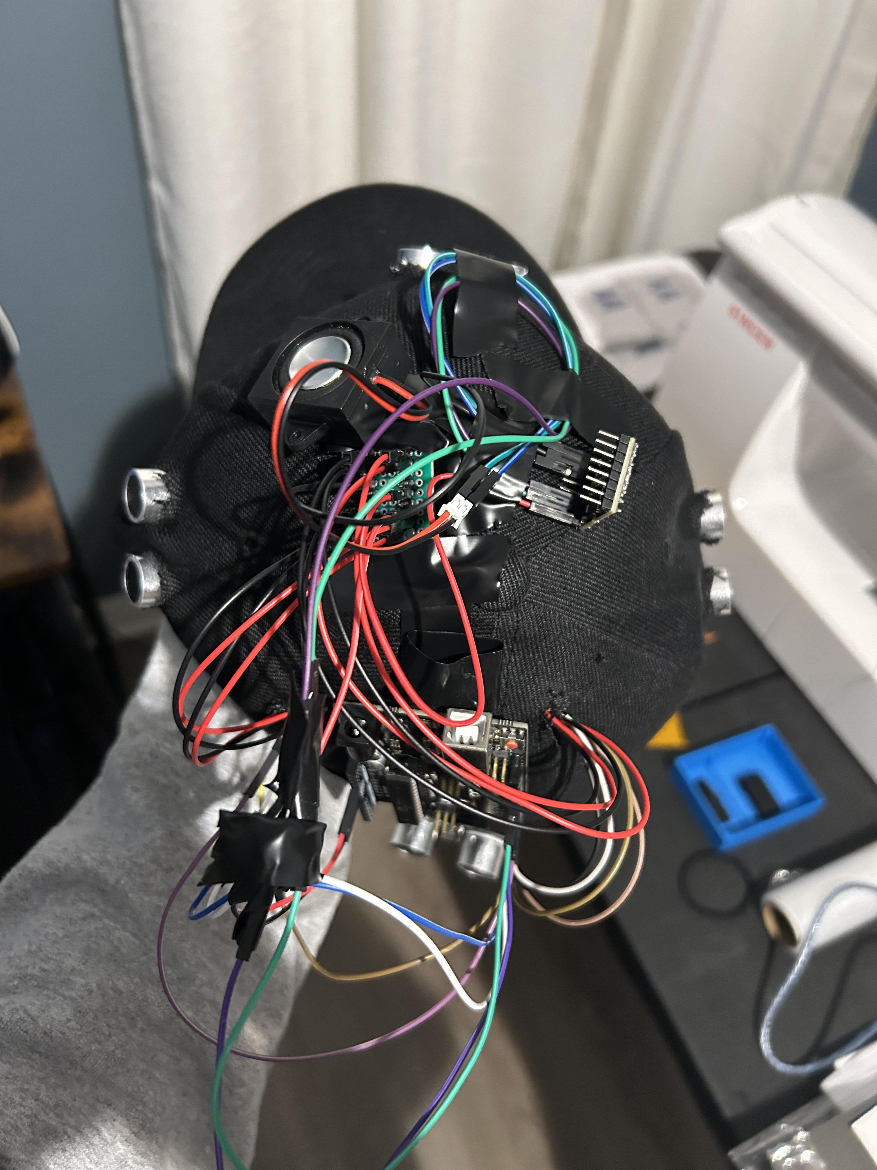
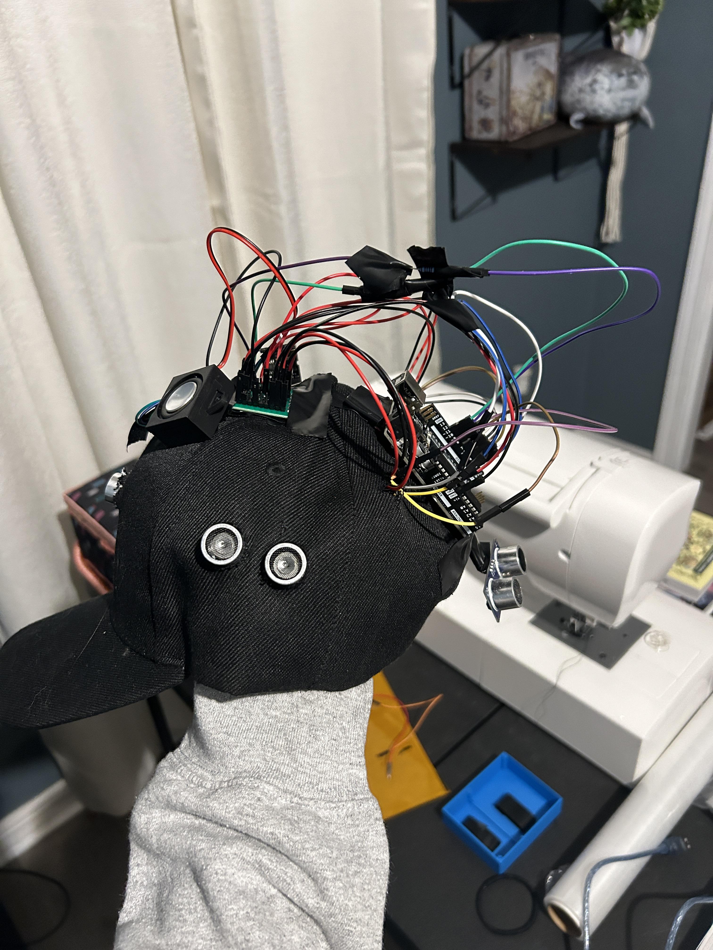
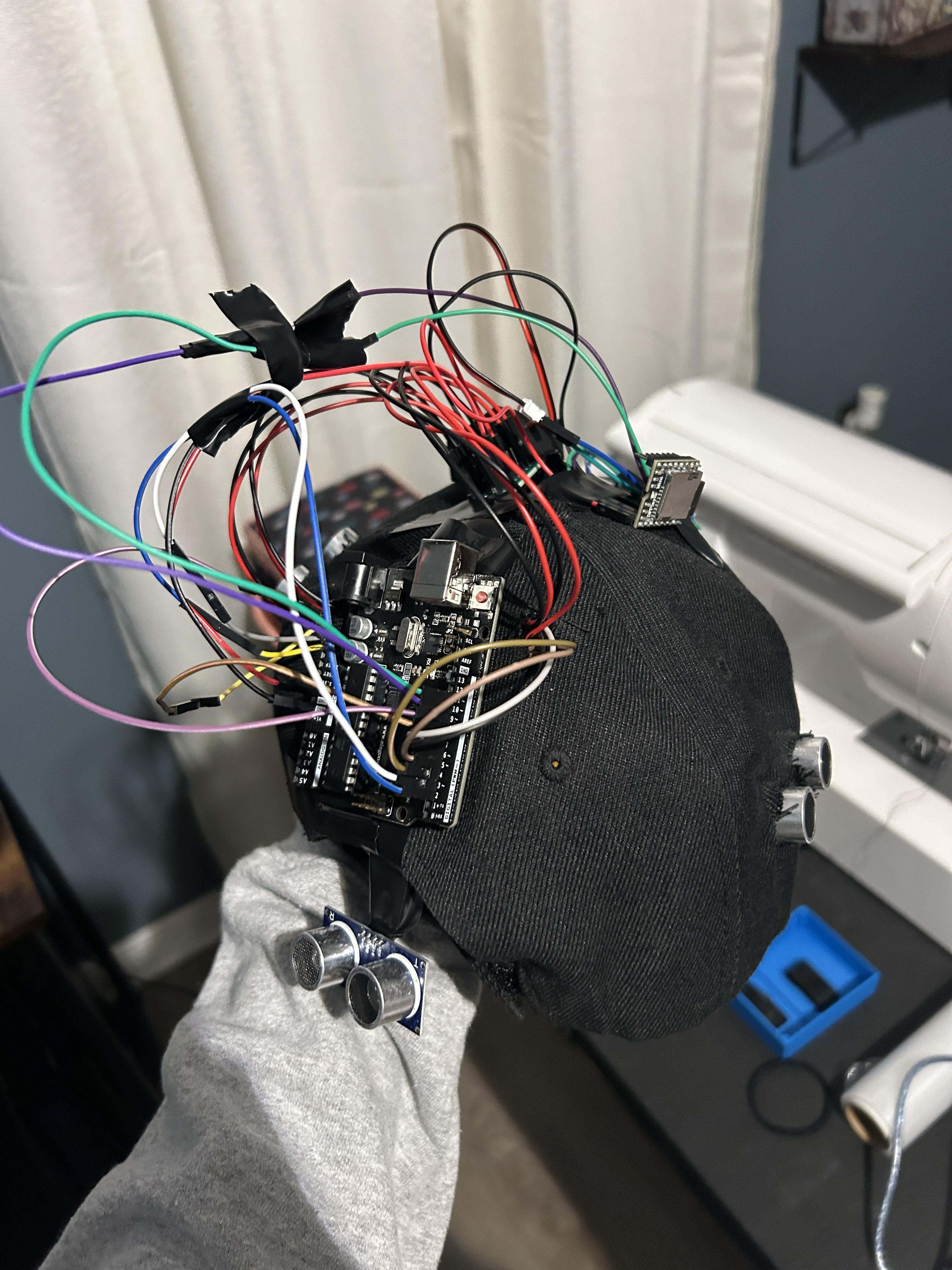
Cut two exit holes through the back of the hat, where all of the wires will meet and neatly connect to the Uno board without looking too messy. If you have the access to a 3d printer, I would highly recommend creating a box to hold your Uno board, power bus, and wires (I attempted to do this but made one too small :( )
You can use whichever type of adhesive you'd like to secure all of your wires and sensors, I personally used electric tape. Through the same holes in the rear, you will feed all of the wires for the DFPlayer Mini and your speaker. You will attach them to the top of the hat and secure them in place.
Finally, organize your wires and tape them however you feel is neat enough. Connect your Arduino to your batteries and have fun with your Social Distancer 3000!