Social Distance Sensor
During the Coronavirus Pandemic, are you always wondering if you are socially distanced? Well with this simple project you will always know if you are keeping your distance from other people.
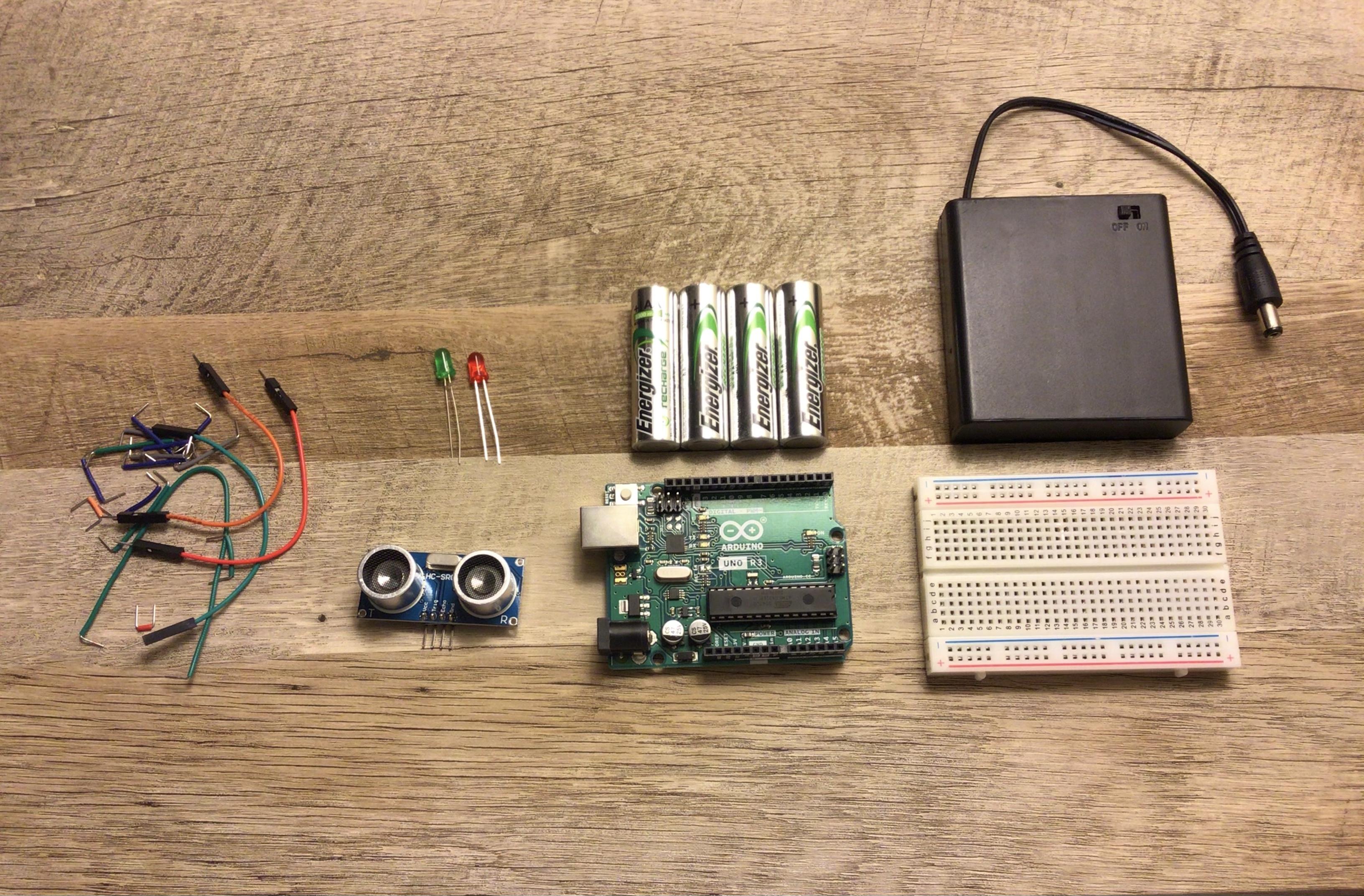
Supplies
You can get these supplies from anywhere
Optional supplies
- Cardboard
- tape
- scissors
Wiring the Distance Sensor
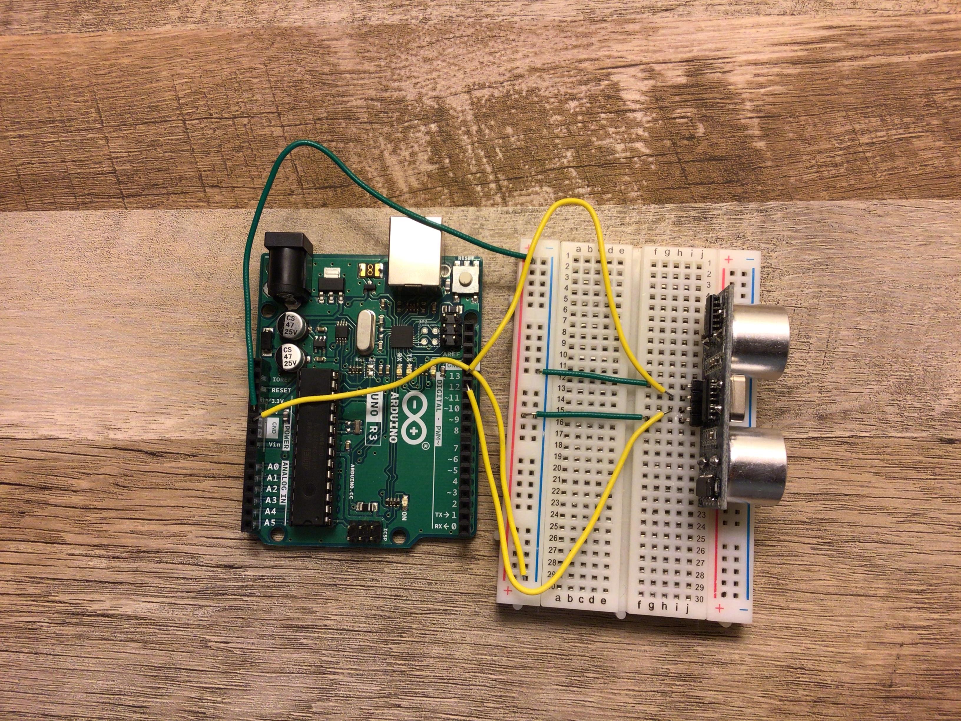
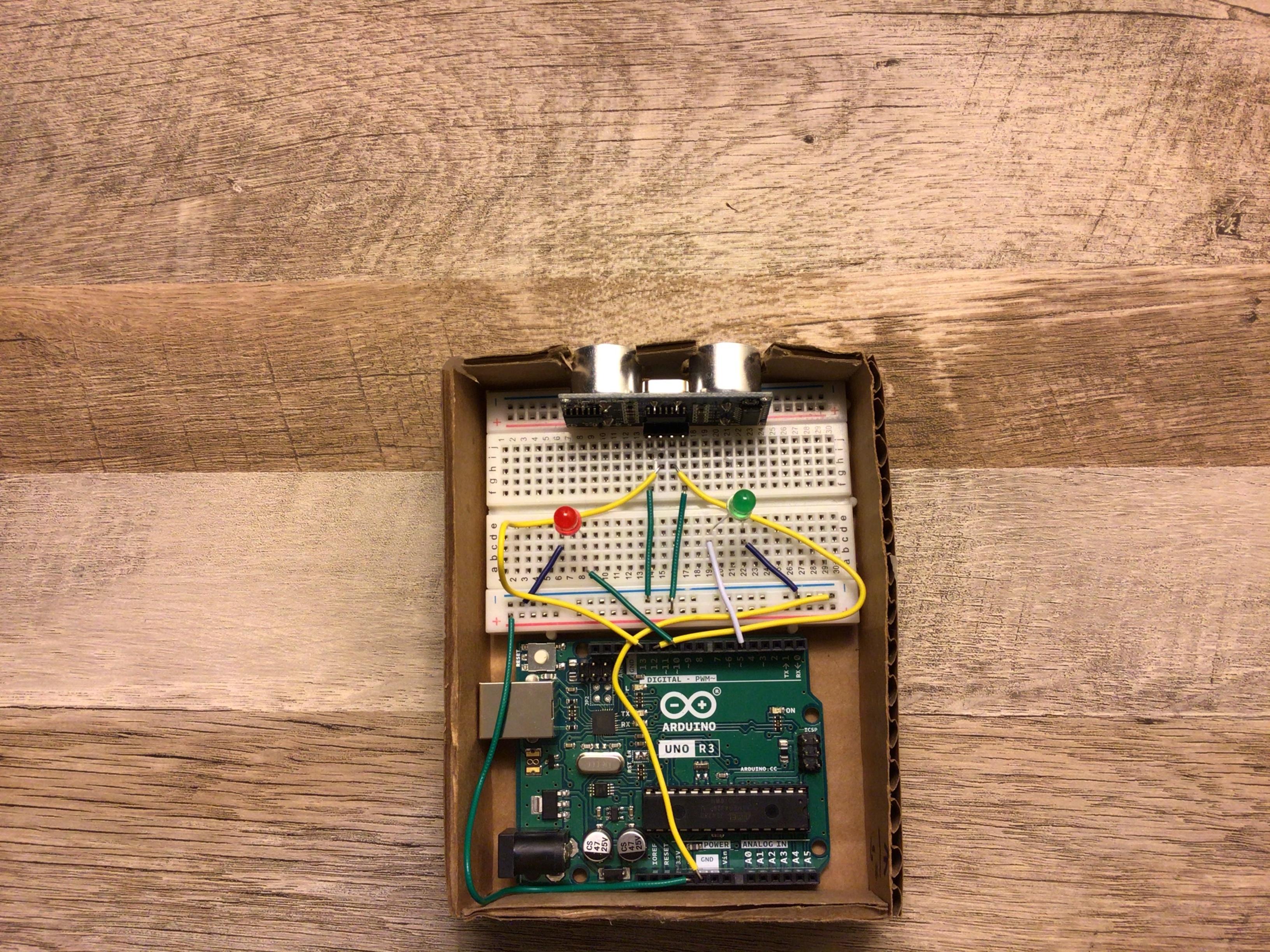
We are first going to start by wiring our distance sensor. This is the part that sends out sonar signals and receives them.
- Connect the 5v pin on the Arduino to the positive power rail (red line) on the breadboard
- Connect the GND pin on the Arduino to the negative power rail (black line) on the breadboard
- Connect pin 13 on the Arduino to the echo pin on the distance sensor
- Connect pin 12 on the Arduino to the trig pin on the distance sensor
- Connect the negative power rail to the GND pin an the distance sensor
- Connect the positive power rail to the Vcc pin on the distance sensor
Wiring the LEDs
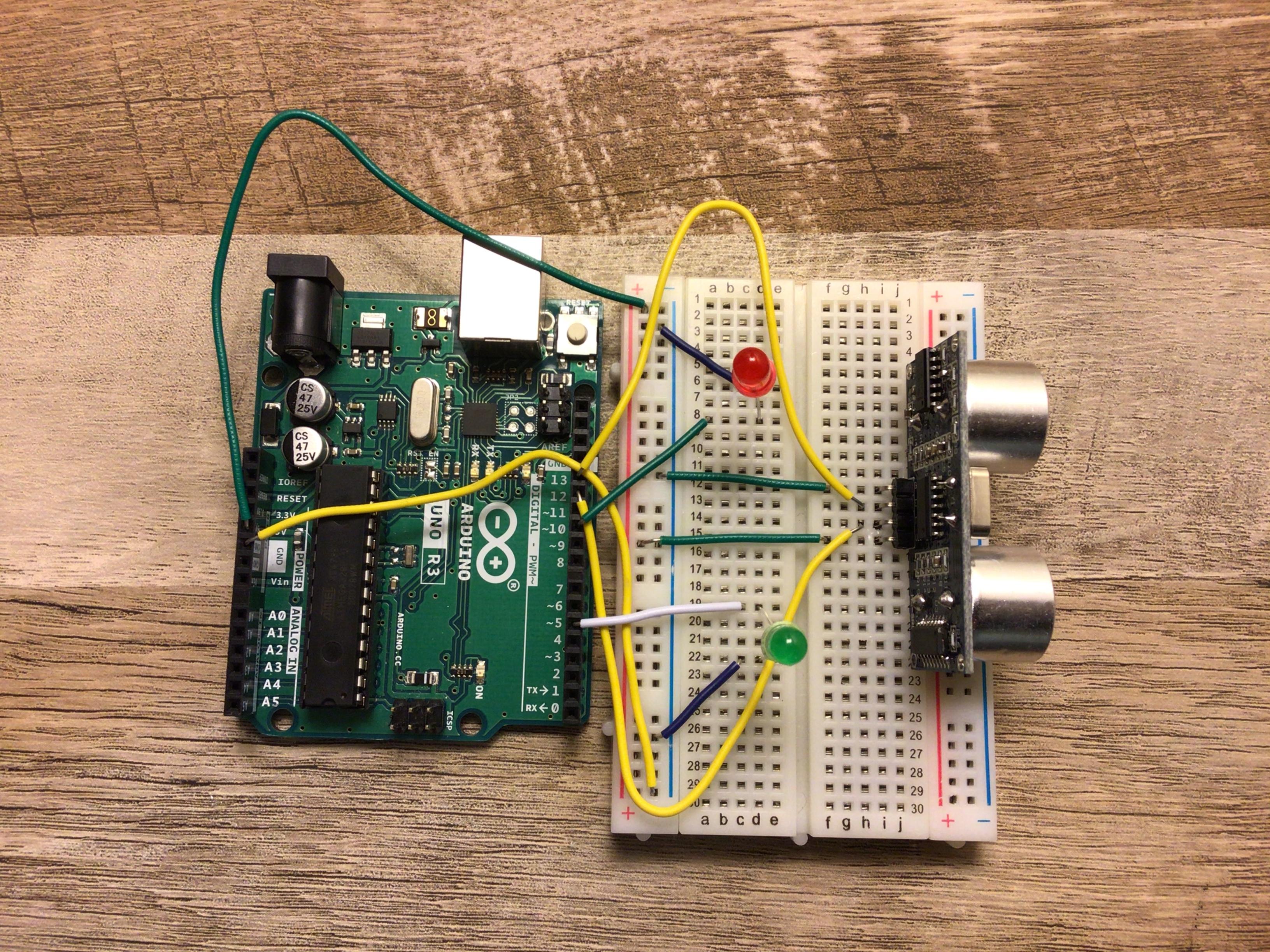
Now that we wired our distance sensor we can now wire our LED's. This will help us indicate if we are too close.
- Get the green LED and the red LED an plug them in to the breadboard in different spots
The Red LED
- now connect the negative power rail on the breadboard to the cathode of the LED (short side)
- now connect pin 10 on the Arduino to the anode of the red LED (long side)
The Green LED
-
now on the other LED connect the negative power rail on the breadboard to the cathode of the LED (short side)
-
now connect pin 5 on the Arduino to the anode of the green LED (long side)
Checking the Wiring
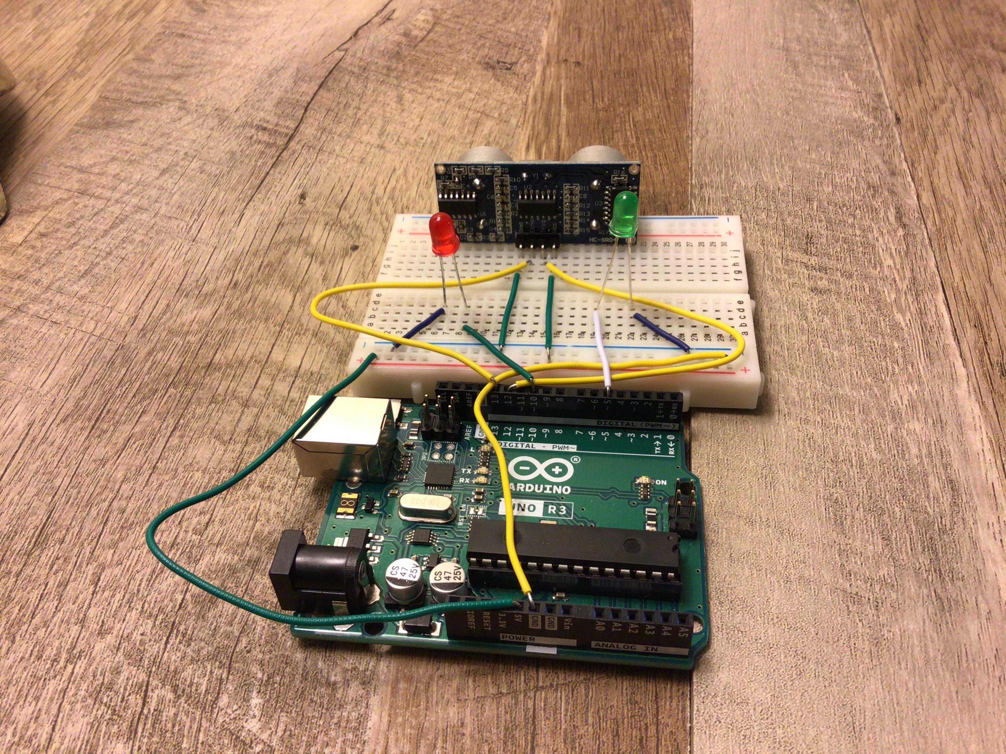
This is what your final wiring should look like.
The Code
This is the code that will run our project. when you are done verify and upload the code.
#define trigPin 12                           //
#define echoPin 13                           //declaring our variables
#define led 10 //red LED                     //
#define led2 5 //green LED                   //

void setup() {
  Serial.begin (9600);
  pinMode(trigPin, OUTPUT);
  pinMode(echoPin, INPUT);
  pinMode(led, OUTPUT);
  pinMode(led2, OUTPUT);
}

void loop() {
  long duration, distance;
  digitalWrite(trigPin, LOW);
  delayMicroseconds(2);
  digitalWrite(trigPin, HIGH);
  delayMicroseconds(10);
  digitalWrite(trigPin, LOW);
  duration = pulseIn(echoPin, HIGH);
  distance = (duration/2) / 29.1;

  if (distance > 180 || distance < 0){
    digitalWrite(led2,HIGH);    // turn on green LED
    digitalWrite(led,LOW);      // turn off red LED
  }
  else {
    digitalWrite(led,HIGH);   // turn on red LED
    digitalWrite(led2,LOW);   // turn off green LED
  }

    delay(250);
}
Test It
Now that we finished our wiring and our code we can now test it.
if you are having trouble try...
- checking the wiring
- checking if my code matches your code
- if the LED's don't light up then try using new ones ( this happened to me )
Making a Cover
Now we can make a cover for our project to make it look nice.
Cutting the Cardboard
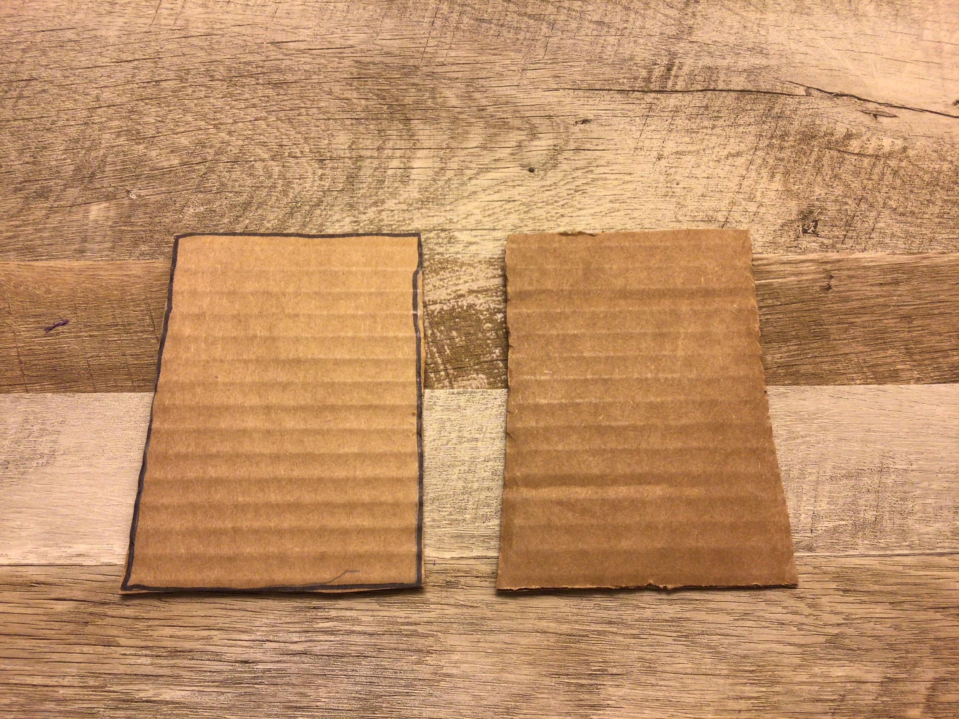
Let’s first start with cutting the cardboard. We will make the top and bottom then we will make the sides. ( NOTE: your cardboard sizes might be different than mine )
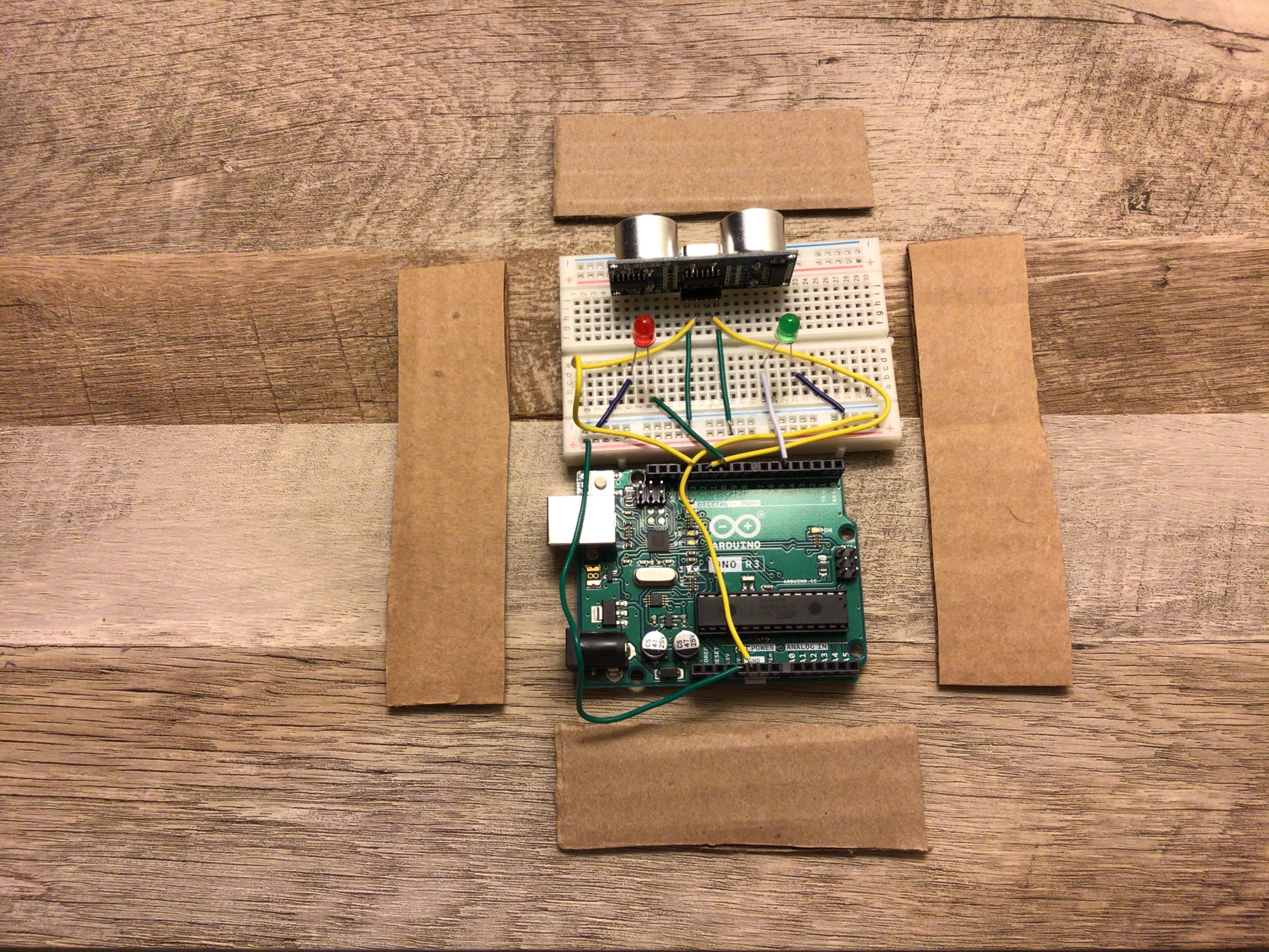
Cutting the Holes for the Distance Sensor
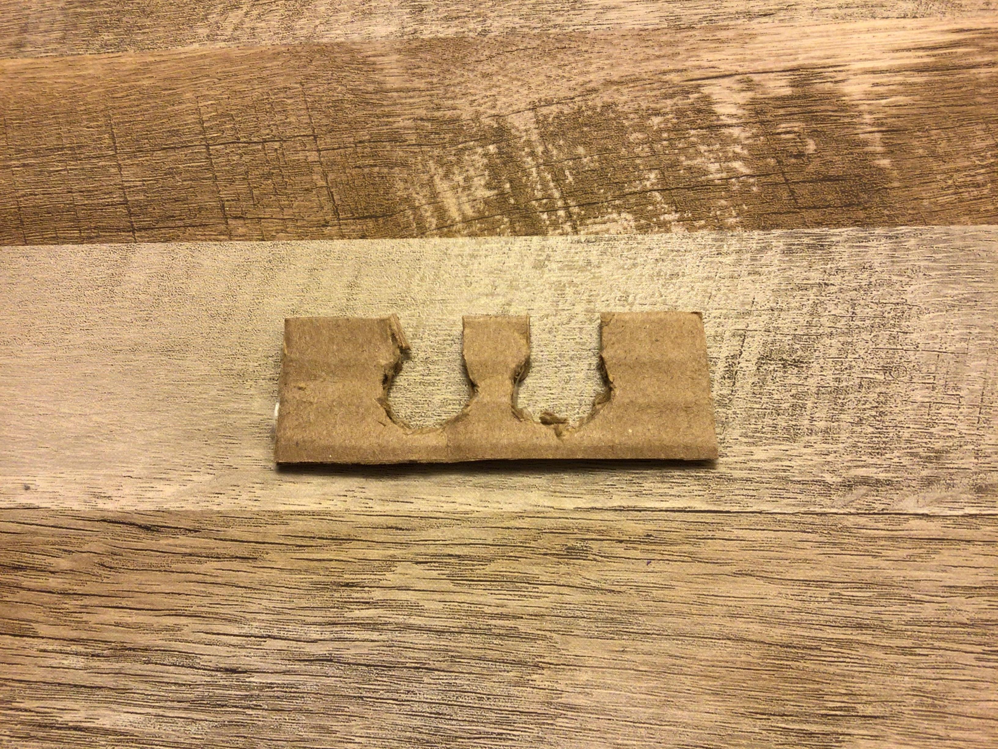
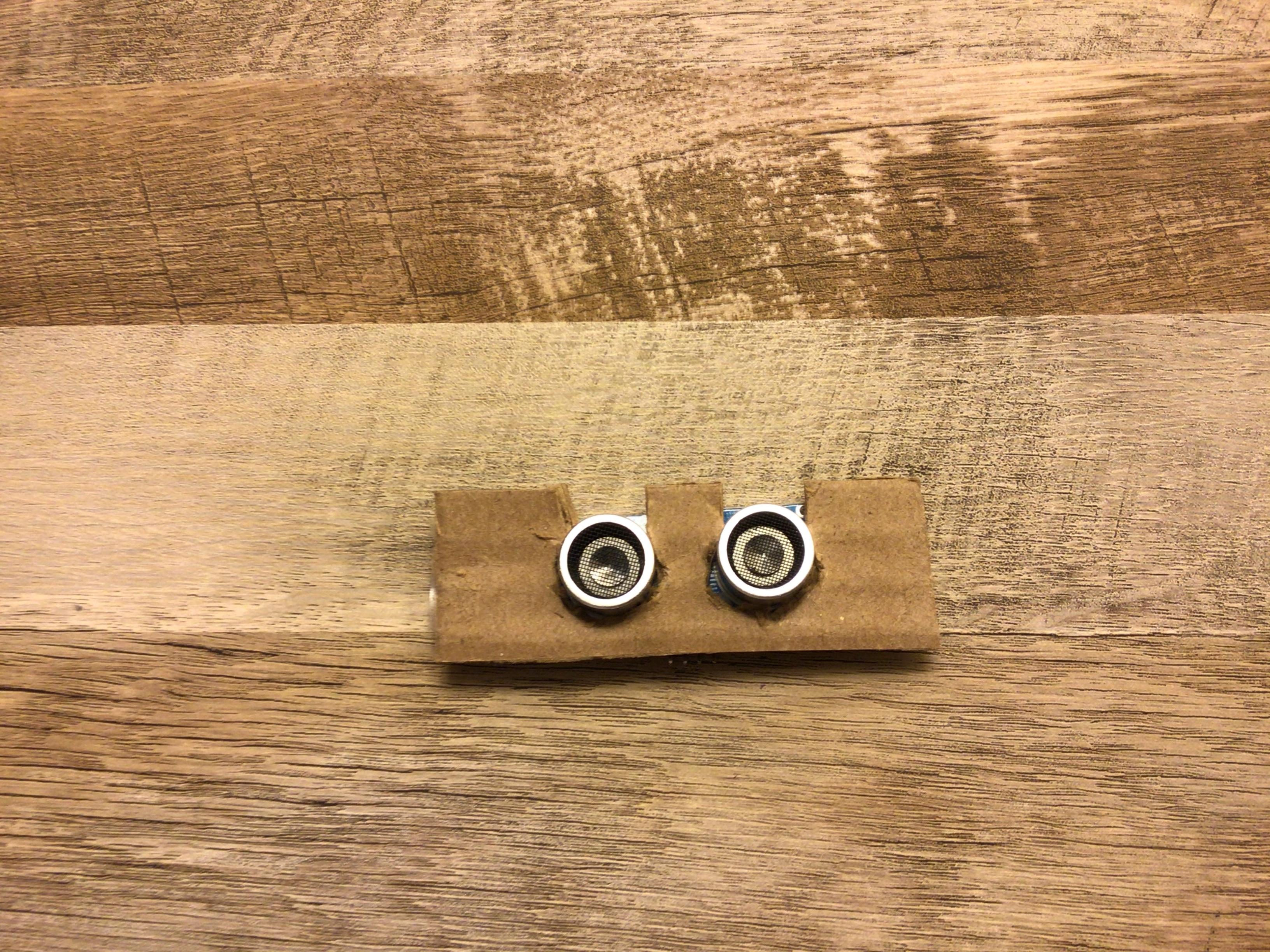
Now pick one of your short sides and cut holes for the distance sensor
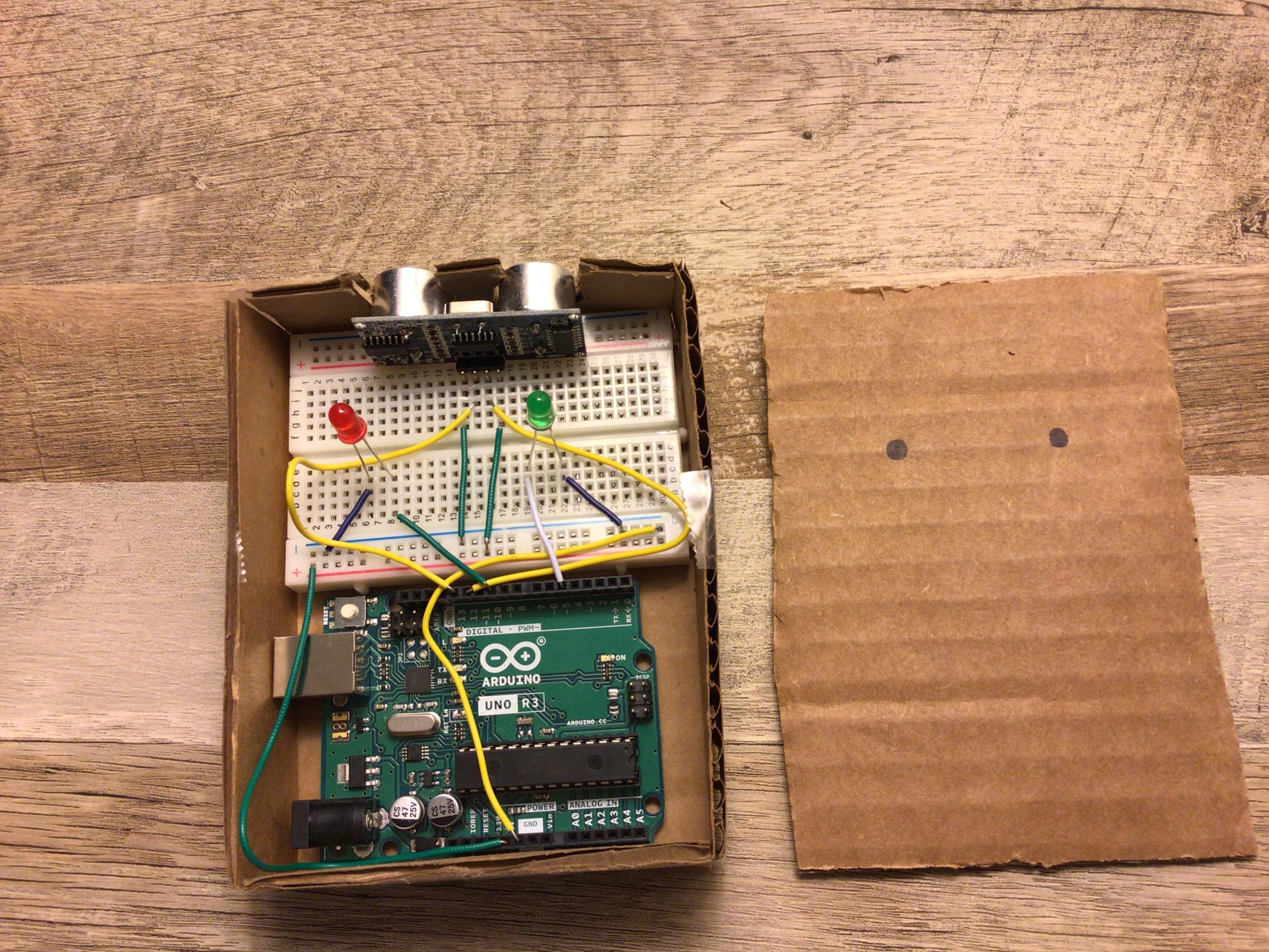
Connecting the Sides
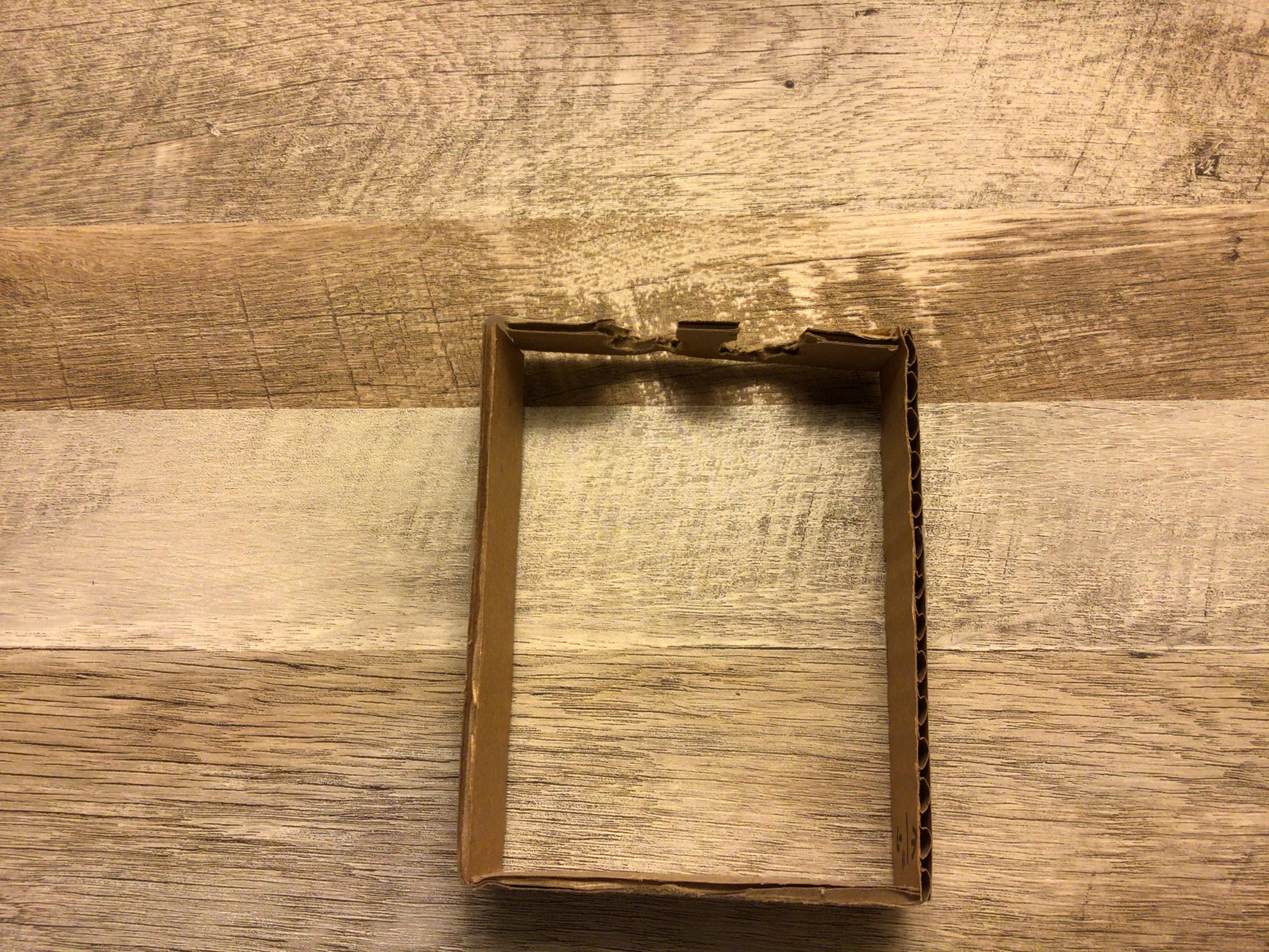
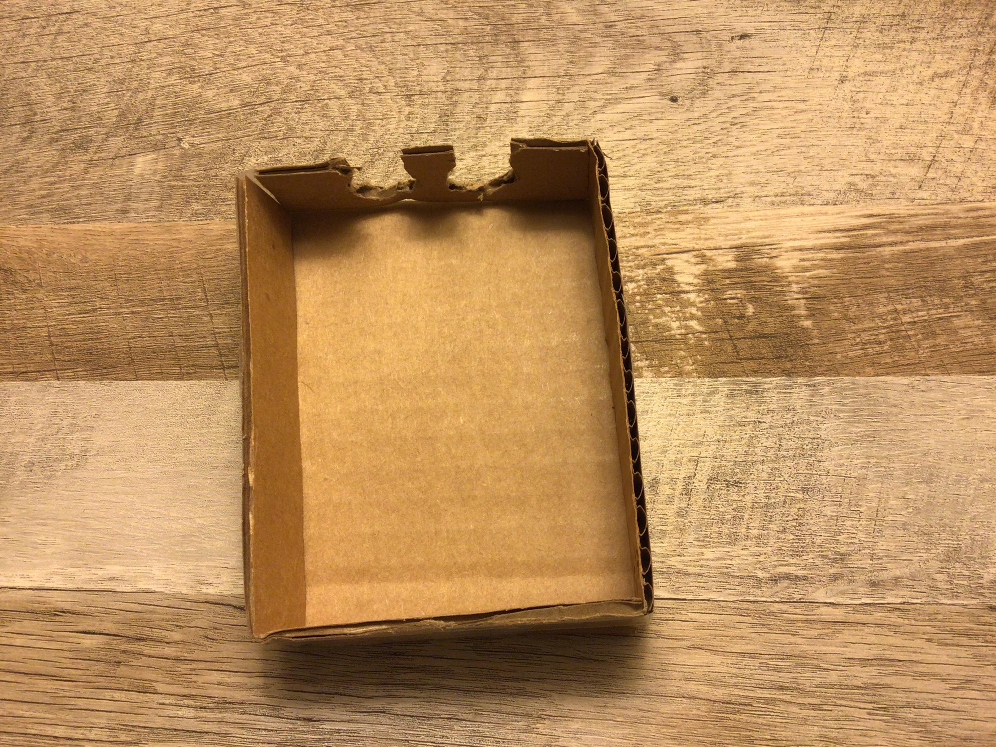
Now take all of your sides and tape them together, then tape that to the bottom. when you are done with that try fitting the Arduino in.
Cutting Holes for the Top
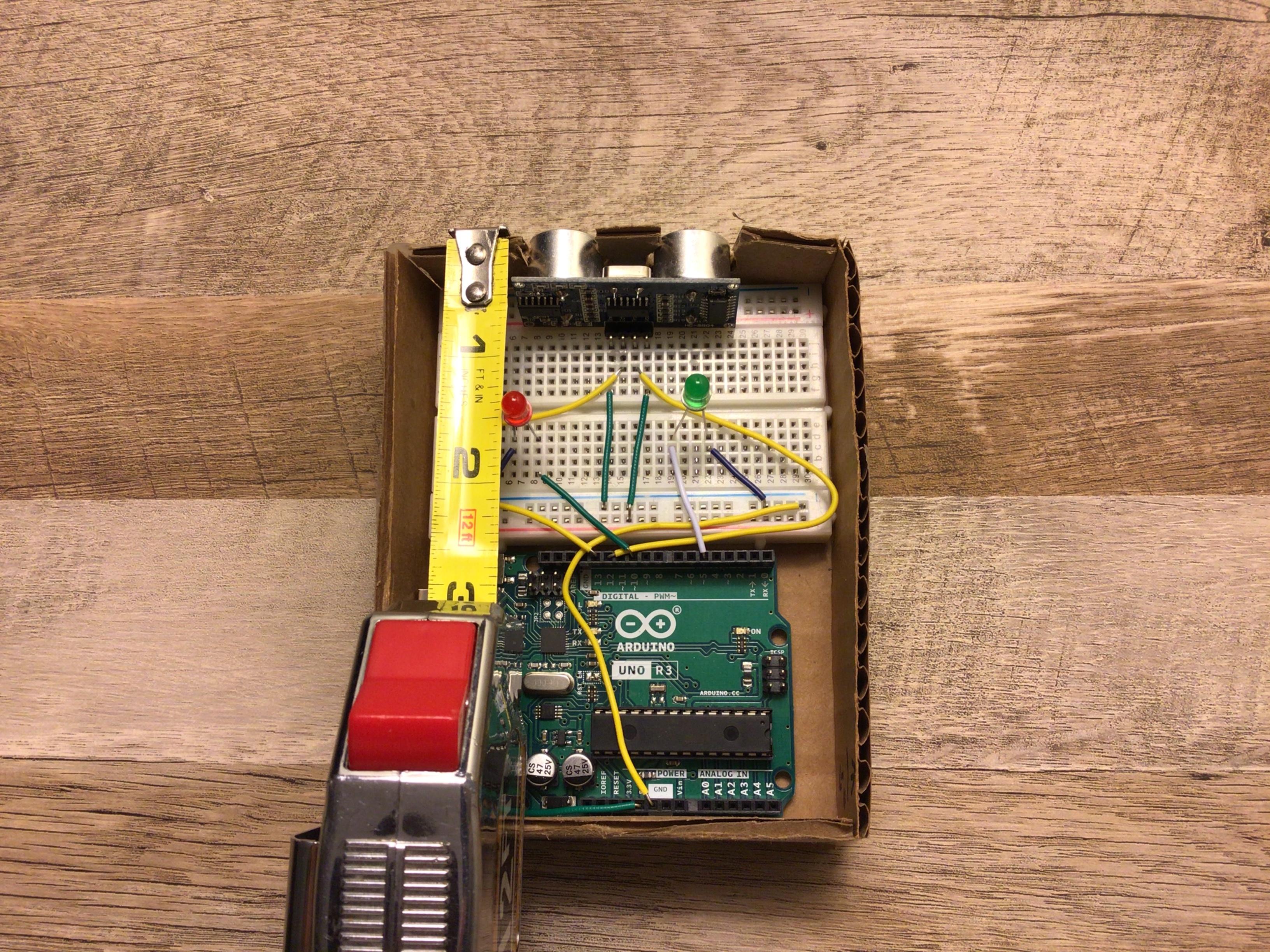
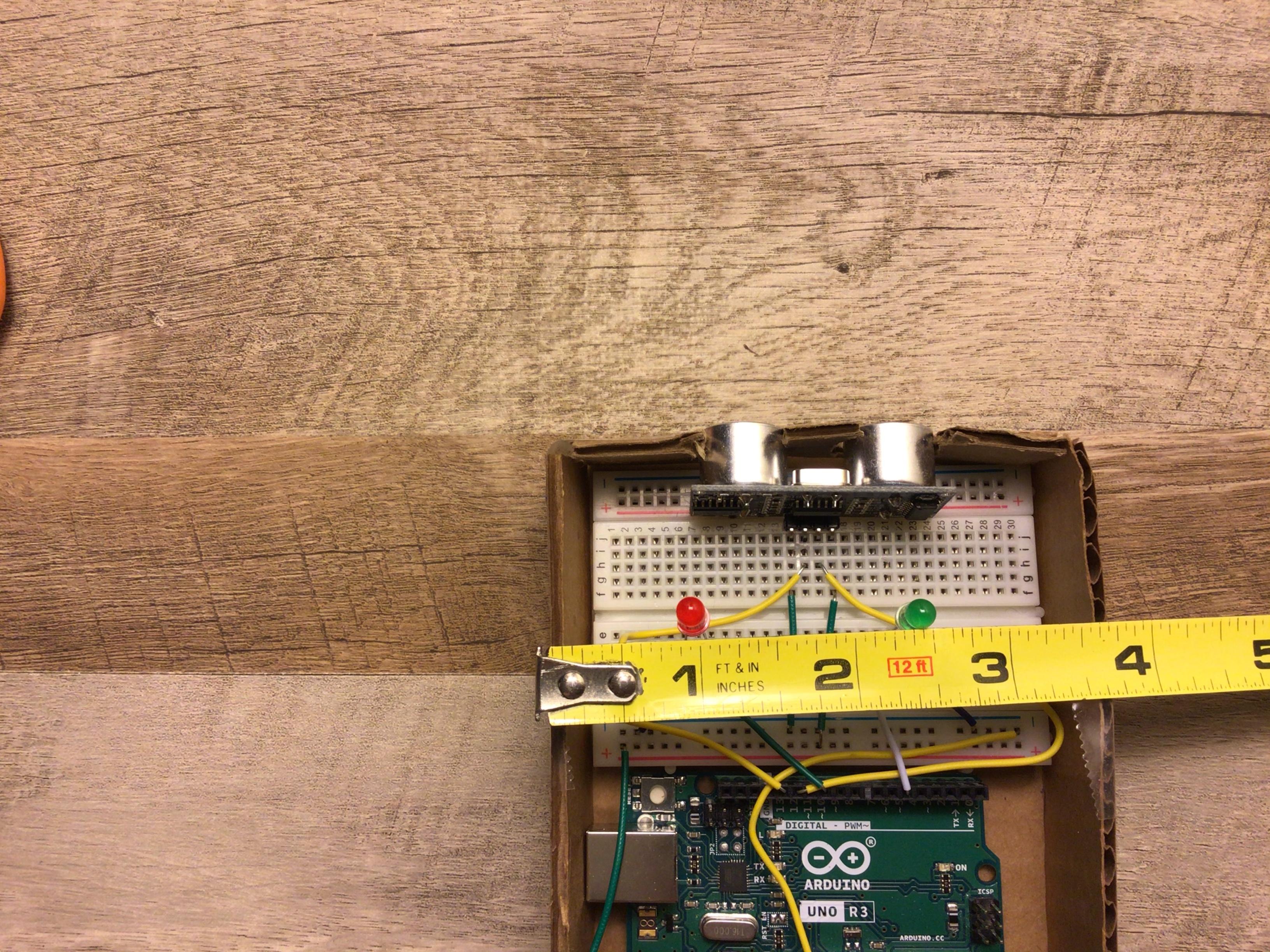
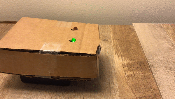
We obviously can’t see the LED's through the cardboard but we can poke holes so we can see the LED's. measure from the distance sensor to the LED then from the side to the LED. on the piece that covers the top do the same measurements and then cut the hole where ever the measurements line up. do the same thing for the other side.
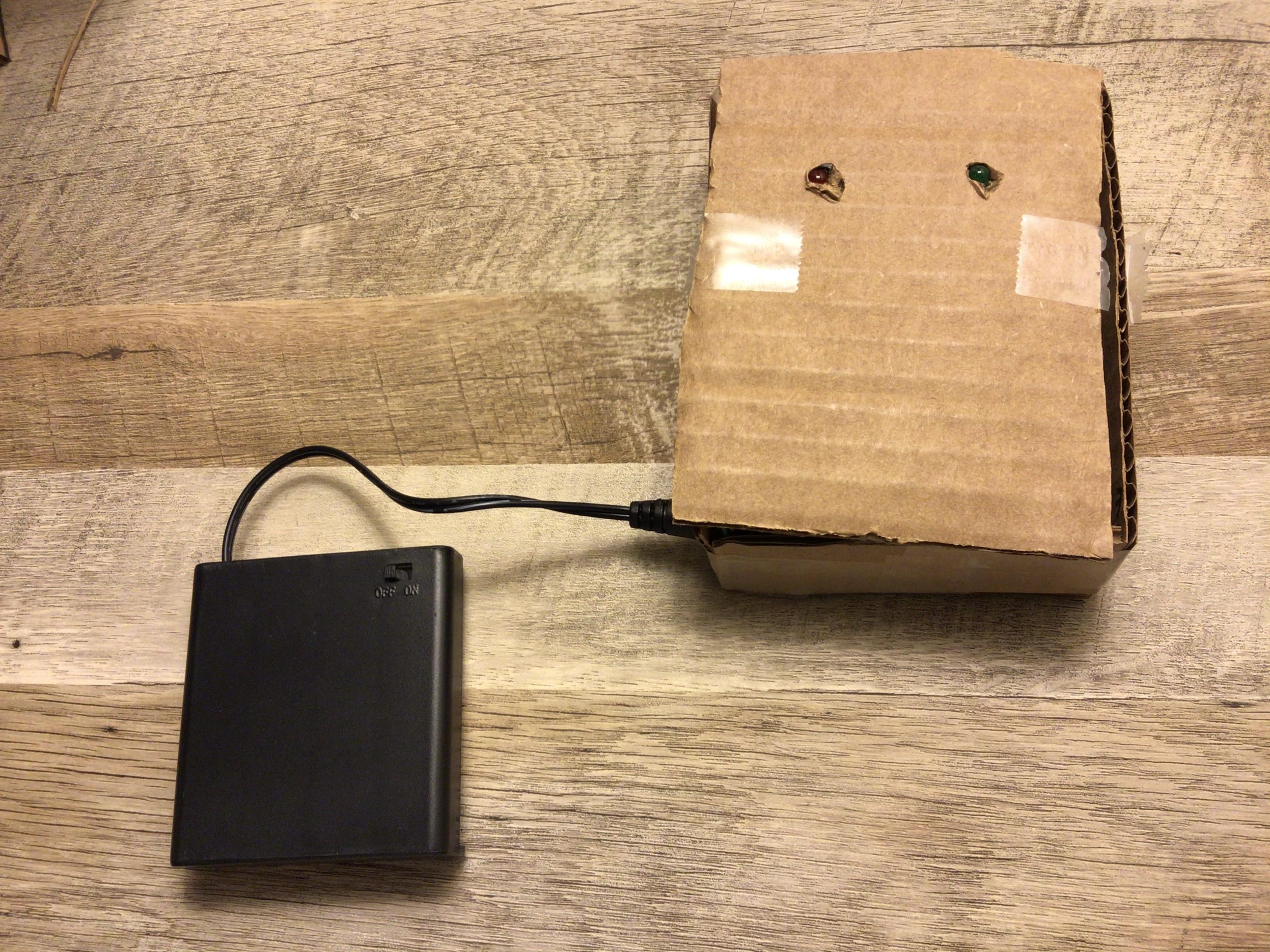
Cutting a Hole for the Battery Pack
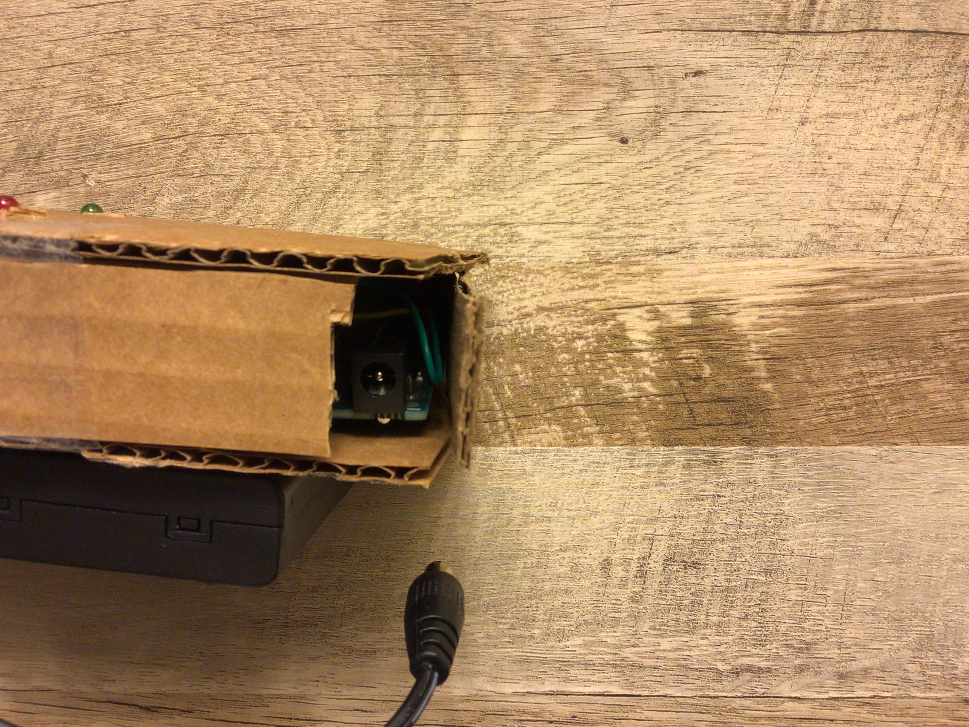
Cut a small hole in the side so we can plug in our battery pack
Your Done!
Now that you have finished you can go check every thing or you can go right ahead and test it.
How It Works
The distance sensor sends out sonar signals and then receives them then will tell which LED to turn on.