SnapNsew: a Soft-Circuit / Embedded Electronic Project
by MakersBox in Circuits > Wearables
6093 Views, 37 Favorites, 0 Comments
SnapNsew: a Soft-Circuit / Embedded Electronic Project
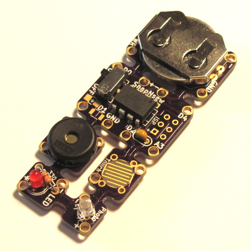
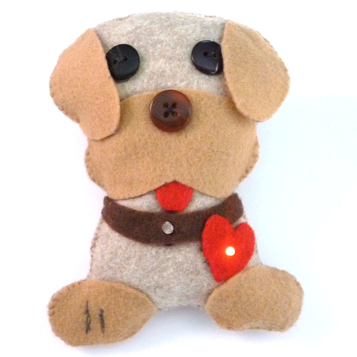
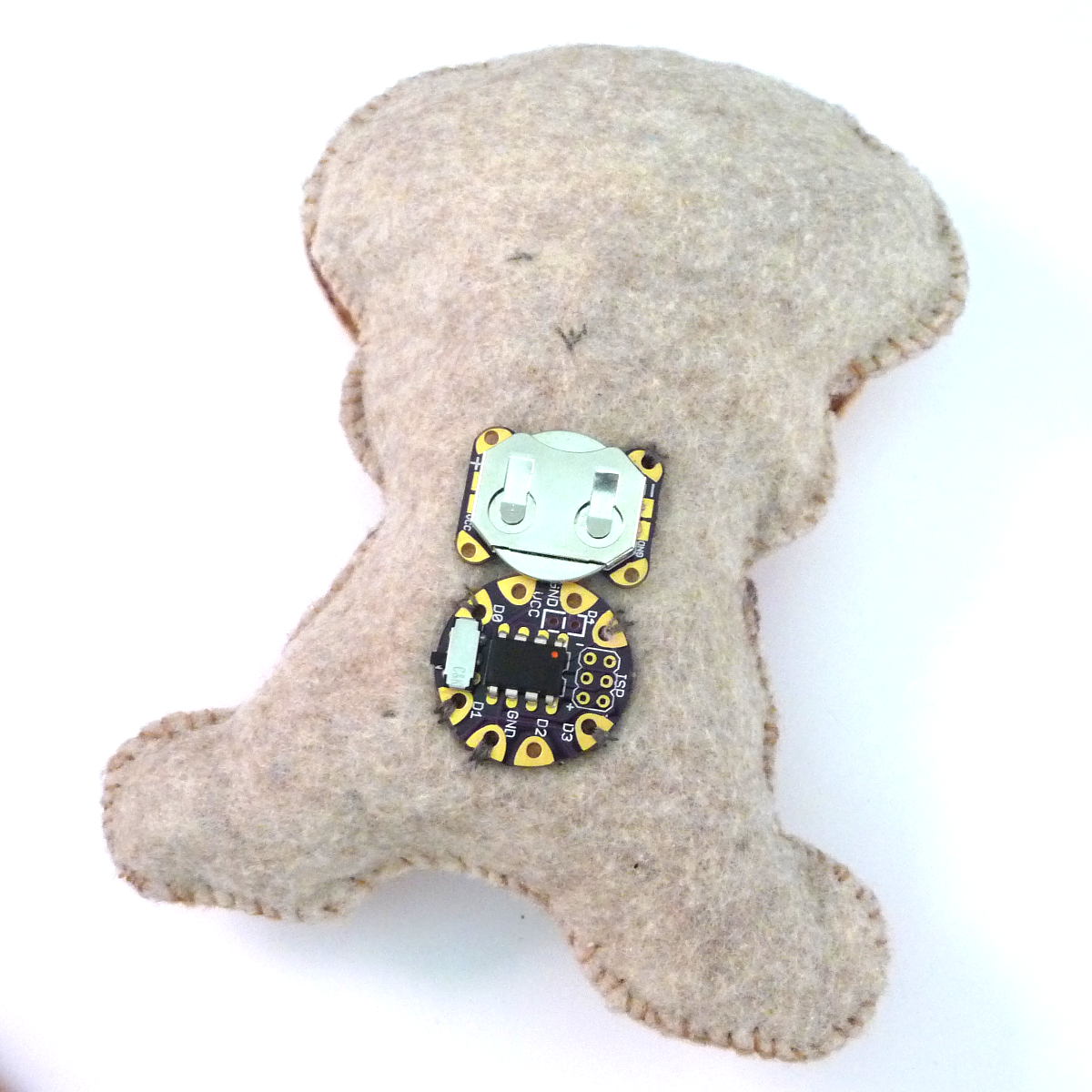
Embedding electronics into textiles is an exciting way to get kids interested in electronics. Unfortunately, the techniques necessary to create a robust project are not trivial. I've created this system which allows you to:
- Easily create and test a working microcontroller circuit with basic inputs and outputs using standard through-hole components and a printed circuit board.
- Snap the pieces apart and easily sew them into a soft circuit project.
This Instructable will cover assembling and testing the circuit. If workshop time allows, and the students are interested, they can learn to solder buy building the boards themselves. If time is limited, or student are younger, the boards can be built and tested ahead of time.
Incorporating the circuitry in to a project will be covered in a second Instructable:https://www.instructables.com/id/Creating-a-Soft-Circuit-Project-with-SnapNsew/
A kit for the electronics and conductive thread is available at Tindie.com.
Rev 2?
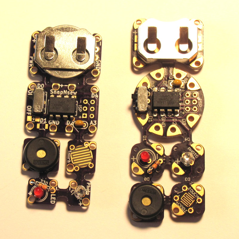
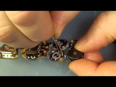
The original SnapNsew was one of my first projects and designed in Eagle Cad. I've progressed quite a bit in my projects, and have always wanted to upgrade this one.
Revision 2:
- Smaller footprint, although loosing the round "starship" look.
- Designed in Open Source KiCad so no need to worry about licensing.
- Pin changes allow PWM on the LED and the speaker to work. Something about internal counters.
- LED and light sensors moved to the end of the board for embedded projects.
So, if you have an original, I've kept the instructions as a PDF, and the assembly video, and some working firmware. You can also still make the original PCB using: https://oshpark.com/shared_projects/BOwDqWcD
Gather the Parts, Tools, and Supplies
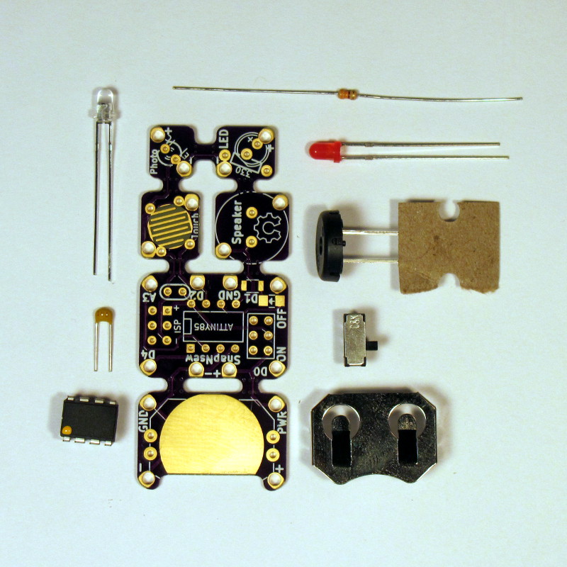
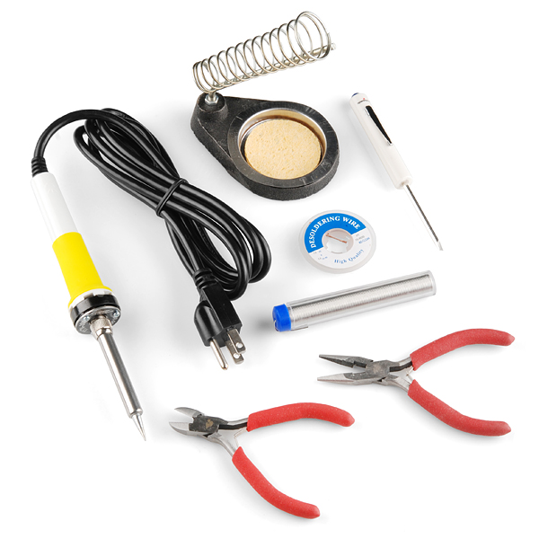
You can build this circuit with a number of various parts, but these are the ones I've found work best:
- 1 - PCB, OSH Park https://oshpark.com/shared_projects/BOwDqWcD
- 1 - Attiny 8-pin microcontroller, Atmel ATTINY85-20PU
- 1 - 20MM Coin cell holder, Linx Technologies In BAT-HLD-001-THM
- 1 - Pizeo speaker, TDK PS1240P02CT3
- 1 - DPDT slide switch, C&K Components JS202011AQN
- 1 - 330 Ohm resistor, 1/8 - 1/4W
- 1 - 3 or 5MM LED, your choice of color
- 1 - Photo transistor or photocell, Light-On Inc LTR-4206
- 0.1 uf Capacitor
Remember, I've done all the hard work if you just want to buy the kit at Tindie.com.
For my classes, I use SparkFun's Beginner's ToolKit which has most of what you need:
- Soldering iron.
- Solder
- Wire nippers
- Desoldering braid (hopefully not needed, but you never know).
You will also need a 3V CR2032 battery and might like to have a multi-meter handy.
Battery
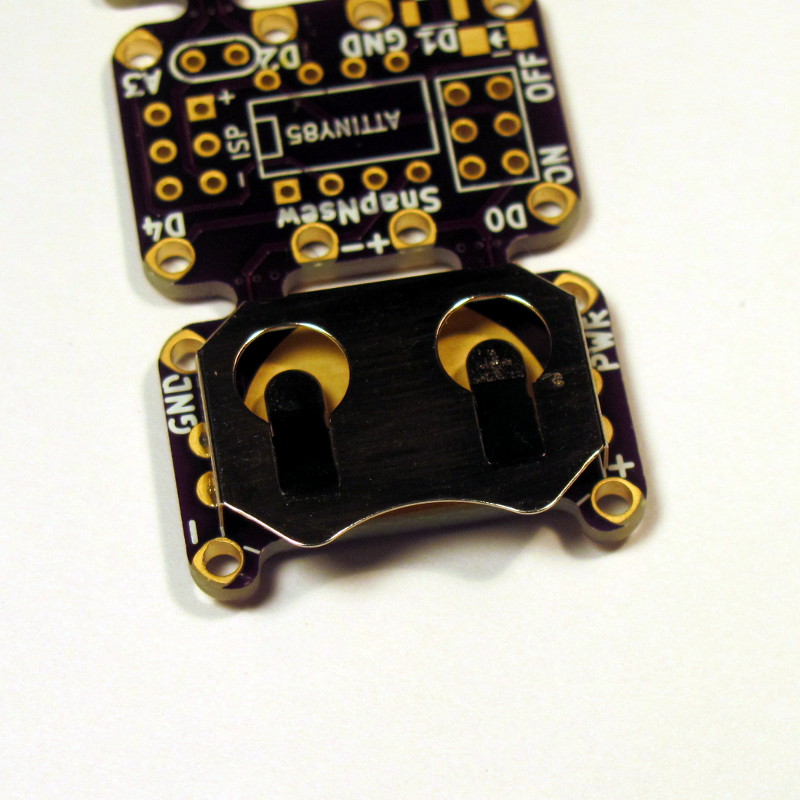
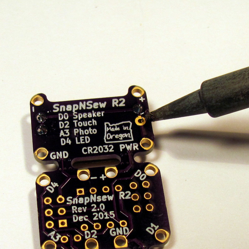
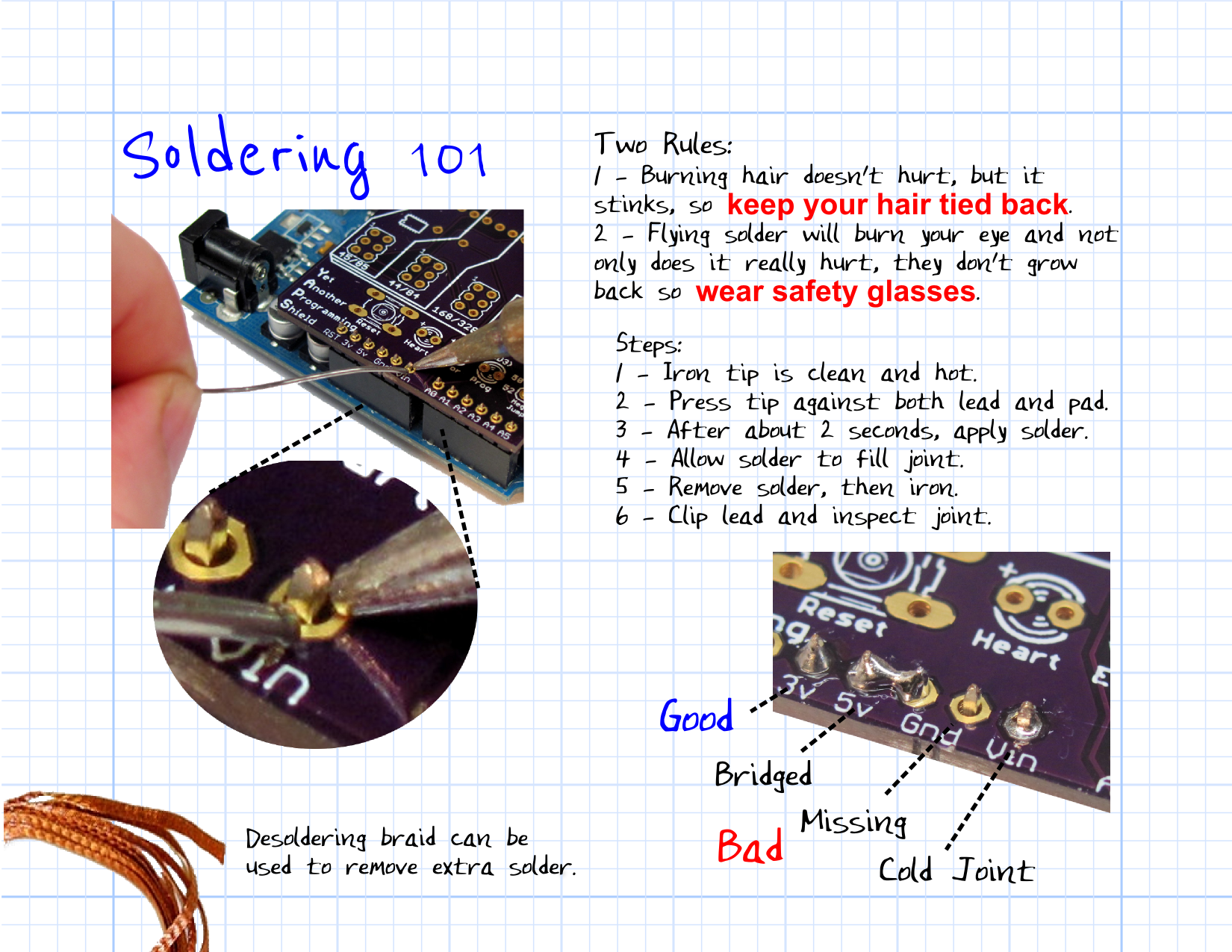
If you have never soldered before, check out SparkFun's tutorial at www.sparkfun.com/tutorials/213 and watch youtu.be/QKbJxytERvg or youtu.be/P5L4Gl6Q4Xo.
We are going to start at the bottom and work our way up.
- Solder the batter with the opening toward the bottom.
Switch, Microcontroller, Capacitor
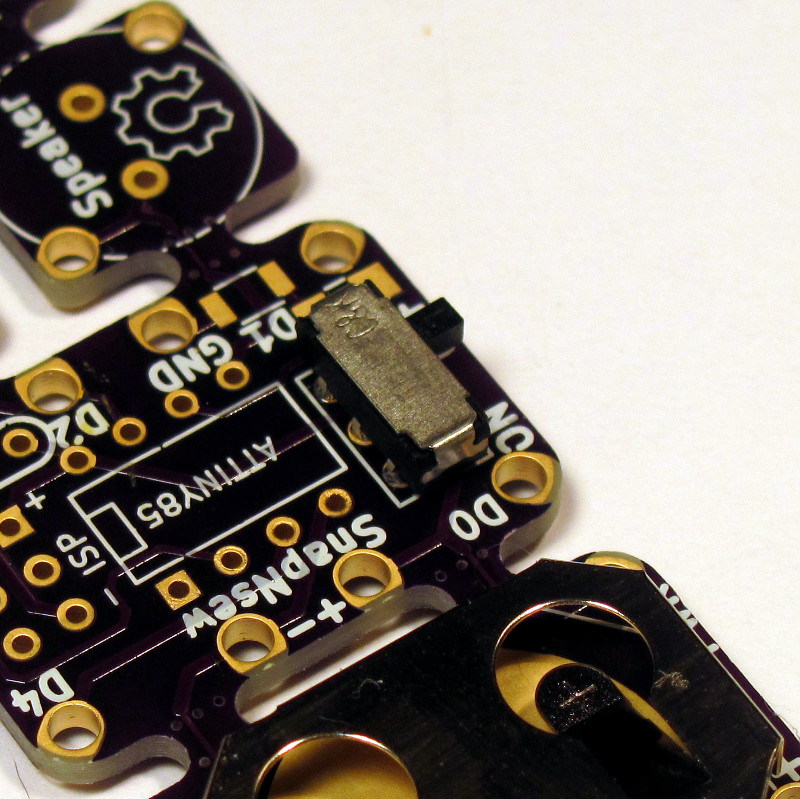
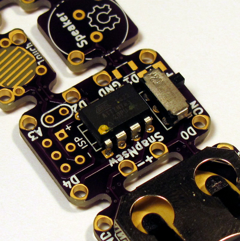
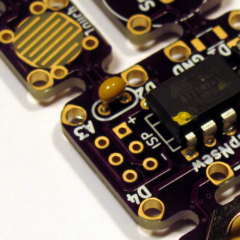
On the next section goes the switch, microcontroller, and capacitor:
- Solder the switch on the right hand side facing outward.
-
Make sure it goes in the correct 6-pin header. One header is for programming, marked "ISP", and the other is for the switch.
-
- Place the Attiny being sure the dot for Pin 1 is toward the ISP header.
- Solder two pins in place.
- Check the alignment and seating.
- Solder the remainder of the pins.
- Install the 0.1uF capacitor in place. It can go in either direction.
Speaker
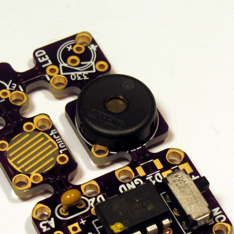
The PS1240 style speaker does not have polarity, so can go in with any orientation.
LED
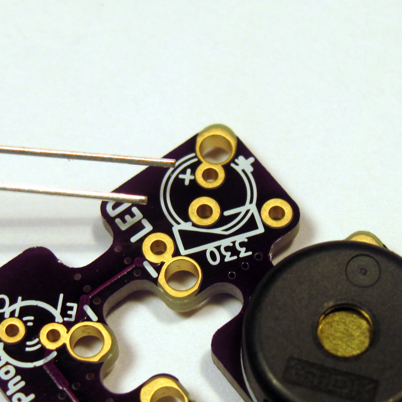
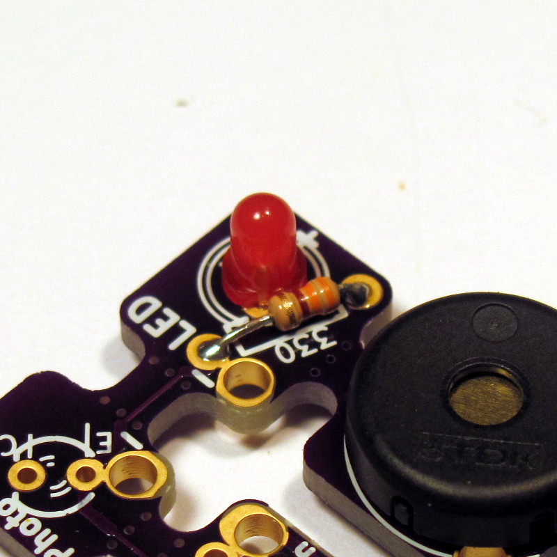
The long lead of an LED goes through the hole marked "+". Most LEDs have a flat side as well, which denotes the negative side. I like having a 3V coin cell handy to test it because I can never remember this.
I usually use a current limiting resistor, even thought the current and voltage supplied by the lithium battery doesn't require it. This will help extend battery life and will also keep the LED safe if you hook a programmer to the ISP (which supplies 5 volts).
If you are using a blue or white LED, you might use a lower resistor value like 180 Ohm, or forgo it completely. Just solder a jumper in place of the resistor.
Light, Touch
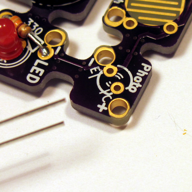
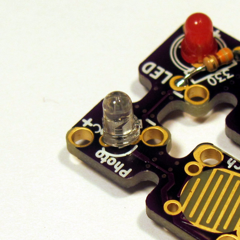
The light detector can be either a cadmium-sulfide photo resistor, or a photo transistor. I like the latter because:
- Its response rate an order of magnitude faster.
- It is cheaper.
- It doesn't contain Cadmium which is toxic should you decide to eat your project or let a baby slobber all over it.
The one draw back is that the photo transistor does have polarity, giving you yet another opportunity to pull your hair out trying to figure out why it doesn't work and then have to learn how to desolder. So, looking at the LTR-4206 data sheet, we can see that the long leg is the emitter, which I think of as negative, and should go in the hole farthest away from the microcontroller. Look closely at the picture if this doesn't make sense.
Power Up and Testing
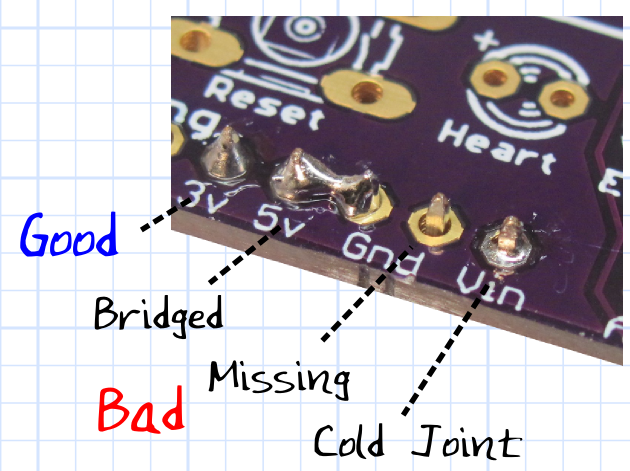
Before we apply power, take a minute to inspect your work. Use a good light and magnifying glass. You are looking for missing or bridges solder joints. Touch up anything that looks suspect.
Insert a fresh 3V CR2032 coin cell with the positive side facing up.
Slide the switch away from the battery (the PCB has an "ON" marking).
Hopefully, you will see the LED flash. This tells you the microcontroller has started, and the number of flashes tells you what mode it is in:
- 1 flash - Music with heartbeat on the LED.
- 2 flashes - Silent with heartbeat on the LED..
Touching the touch pad, or a change in light level, should play the song once (if not silent), and then flash the LEDs for about a minute.
Touching the touch pad while playing or flashing should stop the program.
If it works, you are read to create a soft-circuit project! (see https://www.instructables.com/id/Creating-a-Soft-Circuit-Project-with-SnapNsew/)
If it doesn't work, don't loose heart. Check the next step for troubleshooting.
Troubleshooting

If it doesn't work at first, don't loose heart! Here are some things to check:
- Look at your solder joints. Any missing or bridged connections should be fixed.
- Try a fresh battery, ensuring that the positive side goes away from the PCB
- Use a multi-meter and check the voltage at IC pin 8 (opposite and across from pin 1). It should be 3V.
- If you are getting sound, but not flashing, check the orientation of the LED. I like to use a 3V coin cell to bridge the two leads on the under side of the board. This will tell you if the LED is in the correct position. If it is not, unsolder it and put it in correctly. Here is a good video on how to do it: http://youtu.be/Z38WsZFmq8E
- If all else fails, ask for help. I've tried to make this as easy and fool-proof as possible, but if you are a true beginner, you may need the help of someone more experienced. We create Instructables because we like to share the joy of our hobbies. If you are not successful in building this, you can help me by letting me help you figure out why! We are all learning in one way or another. I'm trying to learn how to make my Instructables better!
Technical Details
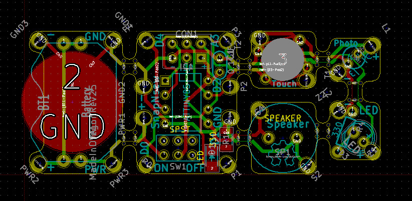
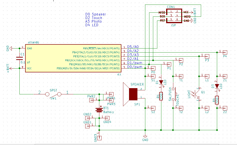
For Revision 2, I started from scratch using the Open Source KiCad project. This means you can modify the project to suit your own needs.
Programming an Attiny is not quite as straight-forward as an Arduino, but can be done. I've actually created a project that lets you use an Arduino and the Arduino IDE to program Attiny chips. Check out: https://www.instructables.com/id/Arduino-AVR-Progamming-Shield/. You can either program the chip before hand using the ZIF socket, or afterwords using the ISP header.
Downloads
Roll the Credits
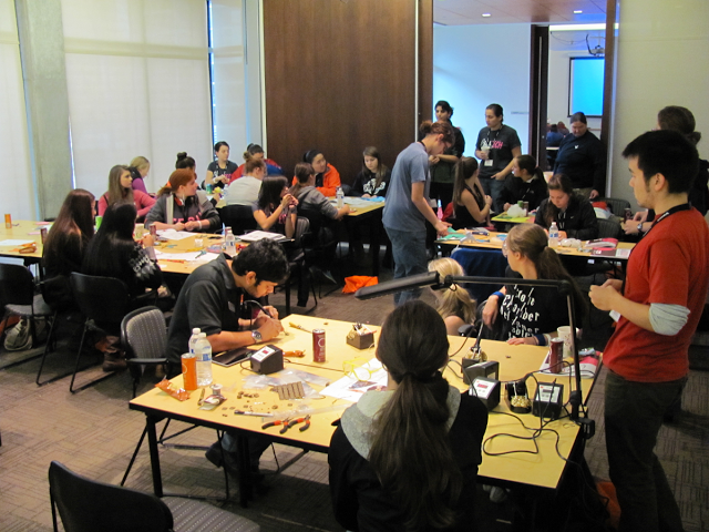
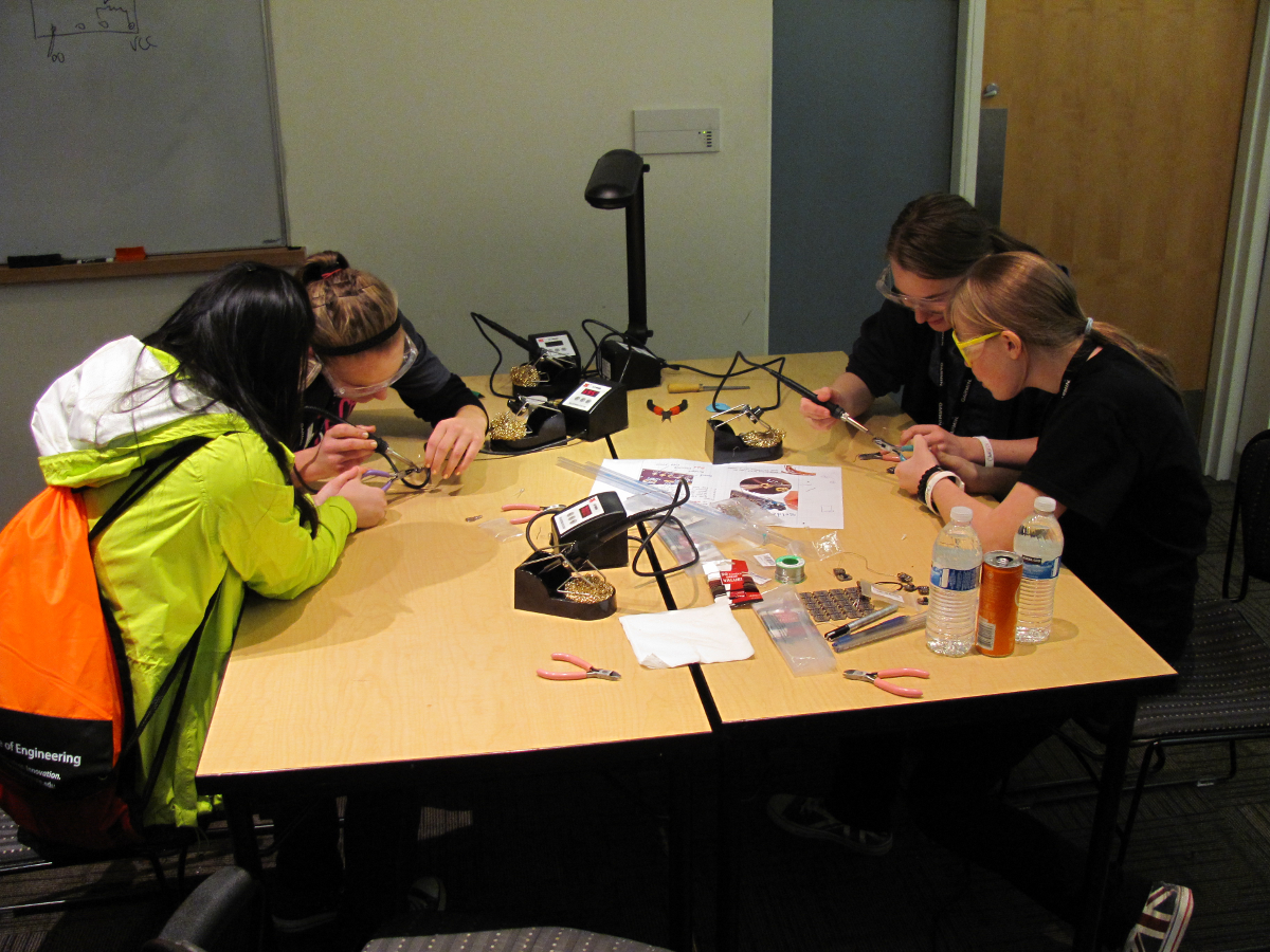
The original idea for this project started with MIT's Soft Circuit Facilitator's Guide and the Lily Twinkle Board. The "snap-a-part" idea is based on LilyPad's ProtoSnap concept. My goal was to make an inexpensive "through-hole" soft-ciruit board allowing multiple input/outputs that could be assembled and tested by the student before being implemented into a soft-circuit project.
I am grateful for ChickTech.org for enabling me to develop this project. Their programs help young women discover career opportunities in engineering fields. This project started as a simple one-hour workshop for teenage girls and as evolved in to an excellent teaching resource that I am hoping to share with other!