Smartroom
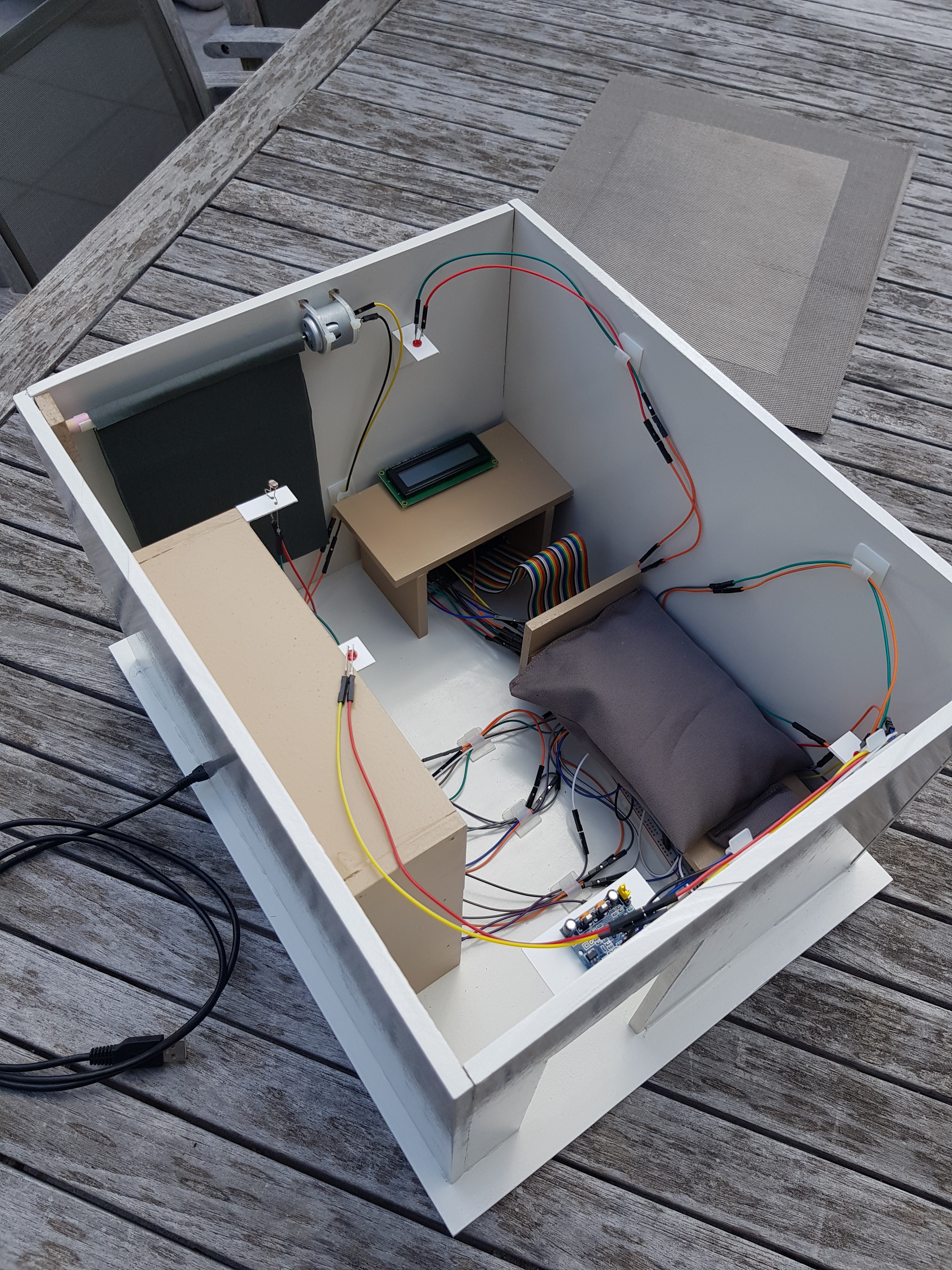
Do you ever feel like laying in your bed and not wanting to get up? Do you ever feel like getting up to open your shutters is to much to ask for? Then I have the perfect solution for you. Introducing Smartroom, take control of your room with your mobile phone, tablet or even your computer!
Supplies
In the next step I will be showing the list of supplies that you will need. Most important of all you will need to have a Raspberry Pi and your computer.
Gathering All of Your Supplies
![20200613_161110[2].jpg](/proxy/?url=https://content.instructables.com/FCY/PE2F/KBF2YG0M/FCYPE2FKBF2YG0M.jpg&filename=20200613_161110[2].jpg)
![20200613_161117[2].jpg](/proxy/?url=https://content.instructables.com/FQZ/34IL/KBF2YG0V/FQZ34ILKBF2YG0V.jpg&filename=20200613_161117[2].jpg)
![20200601_181134[1].jpg](/proxy/?url=https://content.instructables.com/F9J/YPTG/KBF2YG5V/F9JYPTGKBF2YG5V.jpg&filename=20200601_181134[1].jpg)
![20200606_151819[1].jpg](/proxy/?url=https://content.instructables.com/FR8/WHRZ/KBF2YG6T/FR8WHRZKBF2YG6T.jpg&filename=20200606_151819[1].jpg)
![20200601_181152[1].jpg](/proxy/?url=https://content.instructables.com/F0X/4B96/KBF2YG7O/F0X4B96KBF2YG7O.jpg&filename=20200601_181152[1].jpg)
![20200612_194805[1].jpg](/proxy/?url=https://content.instructables.com/FHX/JKQM/KBF2YG7S/FHXJKQMKBF2YG7S.jpg&filename=20200612_194805[1].jpg)
![20200612_194650[1].jpg](/proxy/?url=https://content.instructables.com/FE5/VWK6/KBF2YG7V/FE5VWK6KBF2YG7V.jpg&filename=20200612_194650[1].jpg)
![20200612_194711[1].jpg](/proxy/?url=https://content.instructables.com/FYF/LHW3/KBF2YG8K/FYFLHW3KBF2YG8K.jpg&filename=20200612_194711[1].jpg)
![20200612_201803[1].jpg](/proxy/?url=https://content.instructables.com/FGJ/MQ1F/KBF2YG8L/FGJMQ1FKBF2YG8L.jpg&filename=20200612_201803[1].jpg)
![20200609_110639[1].jpg](/proxy/?url=https://content.instructables.com/FSX/7QWM/KBF2YG7T/FSX7QWMKBF2YG7T.jpg&filename=20200609_110639[1].jpg)
![20200612_194618[1].jpg](/proxy/?url=https://content.instructables.com/FCZ/DAKU/KBF2YG7U/FCZDAKUKBF2YG7U.jpg&filename=20200612_194618[1].jpg)
![20200614_155354[1].jpg](/proxy/?url=https://content.instructables.com/FNH/NYAI/KBF2YGIX/FNHNYAIKBF2YGIX.jpg&filename=20200614_155354[1].jpg)
![20200614_155335[1].jpg](/proxy/?url=https://content.instructables.com/F4Q/6151/KBF2YGIY/F4Q6151KBF2YGIY.jpg&filename=20200614_155335[1].jpg)
![20200614_155320[1].jpg](/proxy/?url=https://content.instructables.com/FGH/4F63/KBF2YGJ1/FGH4F63KBF2YGJ1.jpg&filename=20200614_155320[1].jpg)
![20200614_155308[1].jpg](/proxy/?url=https://content.instructables.com/F7T/GBYM/KBF2YGJ5/F7TGBYMKBF2YGJ5.jpg&filename=20200614_155308[1].jpg)
![20200614_155258[1].jpg](/proxy/?url=https://content.instructables.com/FBV/V5VL/KBF2YGKV/FBVV5VLKBF2YGKV.jpg&filename=20200614_155258[1].jpg)
![20200614_155246[1].jpg](/proxy/?url=https://content.instructables.com/FJ9/9HZS/KBF2YGKX/FJ99HZSKBF2YGKX.jpg&filename=20200614_155246[1].jpg)
![20200614_155416[1].jpg](/proxy/?url=https://content.instructables.com/F2E/WNTS/KBF2YGOU/F2EWNTSKBF2YGOU.jpg&filename=20200614_155416[1].jpg)
Most important, the supplies! I have placed everything in an Excel spreadsheet.
Downloads
Building the Housing
![20200613_161117[1].jpg](/proxy/?url=https://content.instructables.com/FGP/SZSU/KBF2YJ19/FGPSZSUKBF2YJ19.jpg&filename=20200613_161117[1].jpg)
.png)
![20200601_145347[1].jpg](/proxy/?url=https://content.instructables.com/F5N/N5CE/KBF2YJ84/F5NN5CEKBF2YJ84.jpg&filename=20200601_145347[1].jpg)
![20200601_145349[1].jpg](/proxy/?url=https://content.instructables.com/FN8/VG15/KBF2YJ86/FN8VG15KBF2YJ86.jpg&filename=20200601_145349[1].jpg)
![20200609_172830[1].jpg](/proxy/?url=https://content.instructables.com/FDZ/HT34/KBF2YJ87/FDZHT34KBF2YJ87.jpg&filename=20200609_172830[1].jpg)
![20200609_153836[1].jpg](/proxy/?url=https://content.instructables.com/FPX/75XY/KBF2YJ8H/FPX75XYKBF2YJ8H.jpg&filename=20200609_153836[1].jpg)
![20200604_165230[1].jpg](/proxy/?url=https://content.instructables.com/FQS/TNUE/KBF2YJ8F/FQSTNUEKBF2YJ8F.jpg&filename=20200604_165230[1].jpg)
![20200604_165159[1].jpg](/proxy/?url=https://content.instructables.com/F6S/6O1L/KBF2YJ8G/F6S6O1LKBF2YJ8G.jpg&filename=20200604_165159[1].jpg)
![20200601_181152[1].jpg](/proxy/?url=https://content.instructables.com/FV6/NDPU/KBF2YJCG/FV6NDPUKBF2YJCG.jpg&filename=20200601_181152[1].jpg)
![20200606_151819[1].jpg](/proxy/?url=https://content.instructables.com/FUL/KNQQ/KBF2YJSW/FULKNQQKBF2YJSW.jpg&filename=20200606_151819[1].jpg)
![20200601_181134[2].jpg](/proxy/?url=https://content.instructables.com/FIF/8H18/KBF2YJSZ/FIF8H18KBF2YJSZ.jpg&filename=20200601_181134[2].jpg)
![20200601_145354[1].jpg](/proxy/?url=https://content.instructables.com/F9R/XNKO/KBF2YQI5/F9RXNKOKBF2YQI5.jpg&filename=20200601_145354[1].jpg)
![20200613_105614[1].jpg](/proxy/?url=https://content.instructables.com/F4R/YFIS/KBF2YQIN/F4RYFISKBF2YQIN.jpg&filename=20200613_105614[1].jpg)
![20200613_110128[1].jpg](/proxy/?url=https://content.instructables.com/F2A/OXXH/KBF2YQIZ/F2AOXXHKBF2YQIZ.jpg&filename=20200613_110128[1].jpg)
![20200609_174359[1].jpg](/proxy/?url=https://content.instructables.com/F5H/WIG5/KBF2YQJ6/F5HWIG5KBF2YQJ6.jpg&filename=20200609_174359[1].jpg)
![20200613_134635[1].jpg](/proxy/?url=https://content.instructables.com/FBS/GSXY/KBF2YQJR/FBSGSXYKBF2YQJR.jpg&filename=20200613_134635[1].jpg)
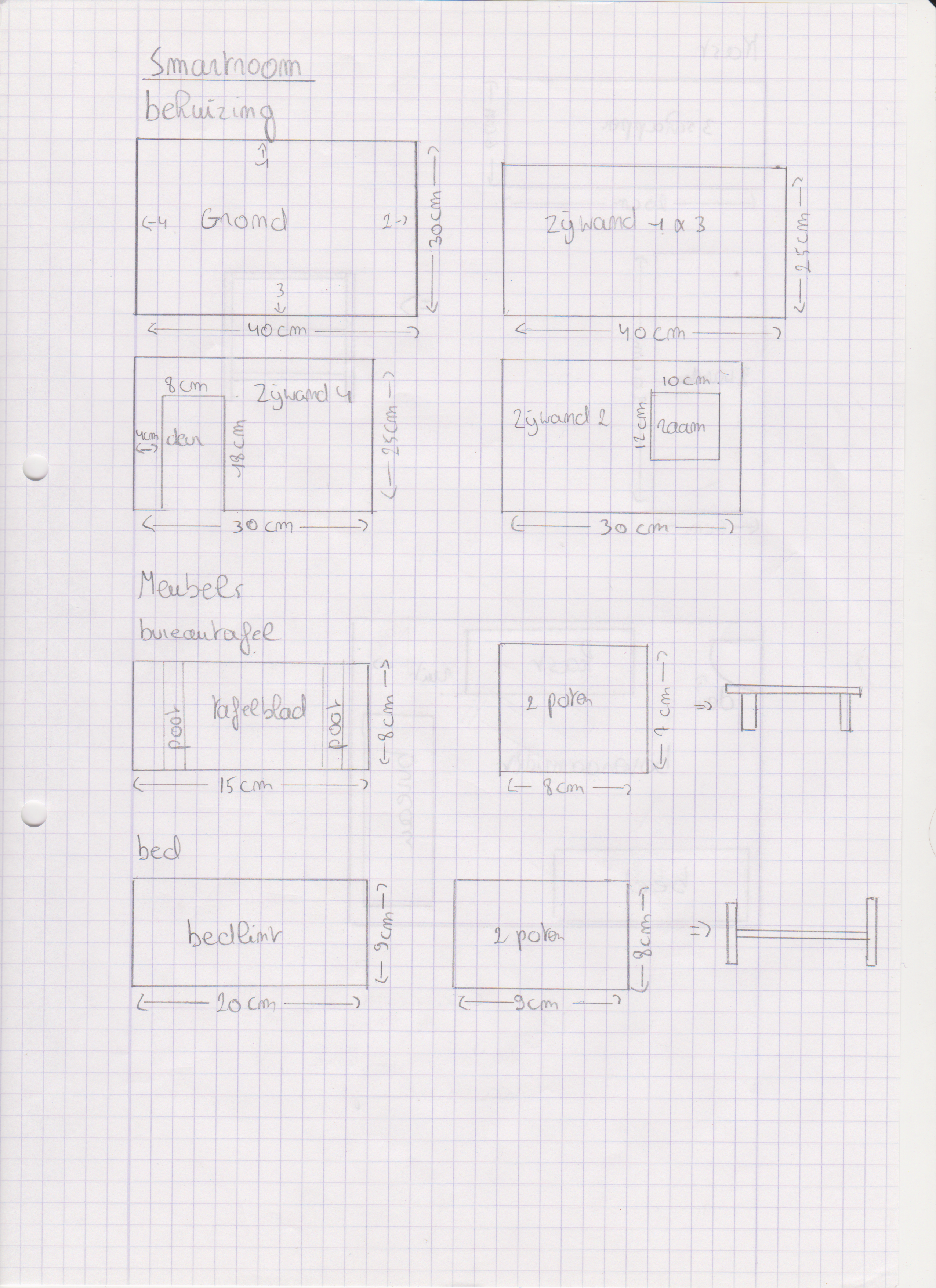
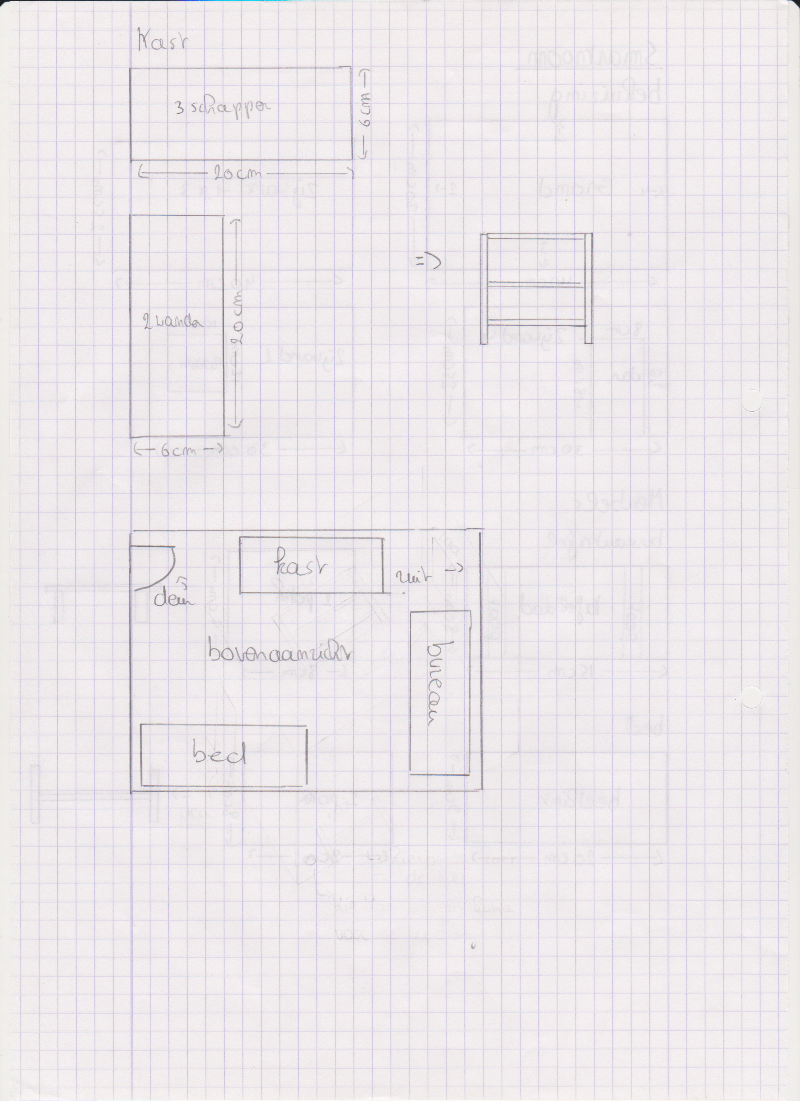
For the housing I used an MDF panel size 122 cm by 61 cm, you can find those at any DIY store. Cut them with a circle blade saw with the dimensions in the drawing. The panels are then glued together with the Soudal Fix All glue. Painting is optional but gives it a nice touch :), I used the types of paint as seen in the pictures above. For the curtains I made a single sheet of the thinnest fabric I had. I also had a plastic tube laying around with a 90 degree angle. I cut those in pieces for the sensors to fit in.
Making the Circuit
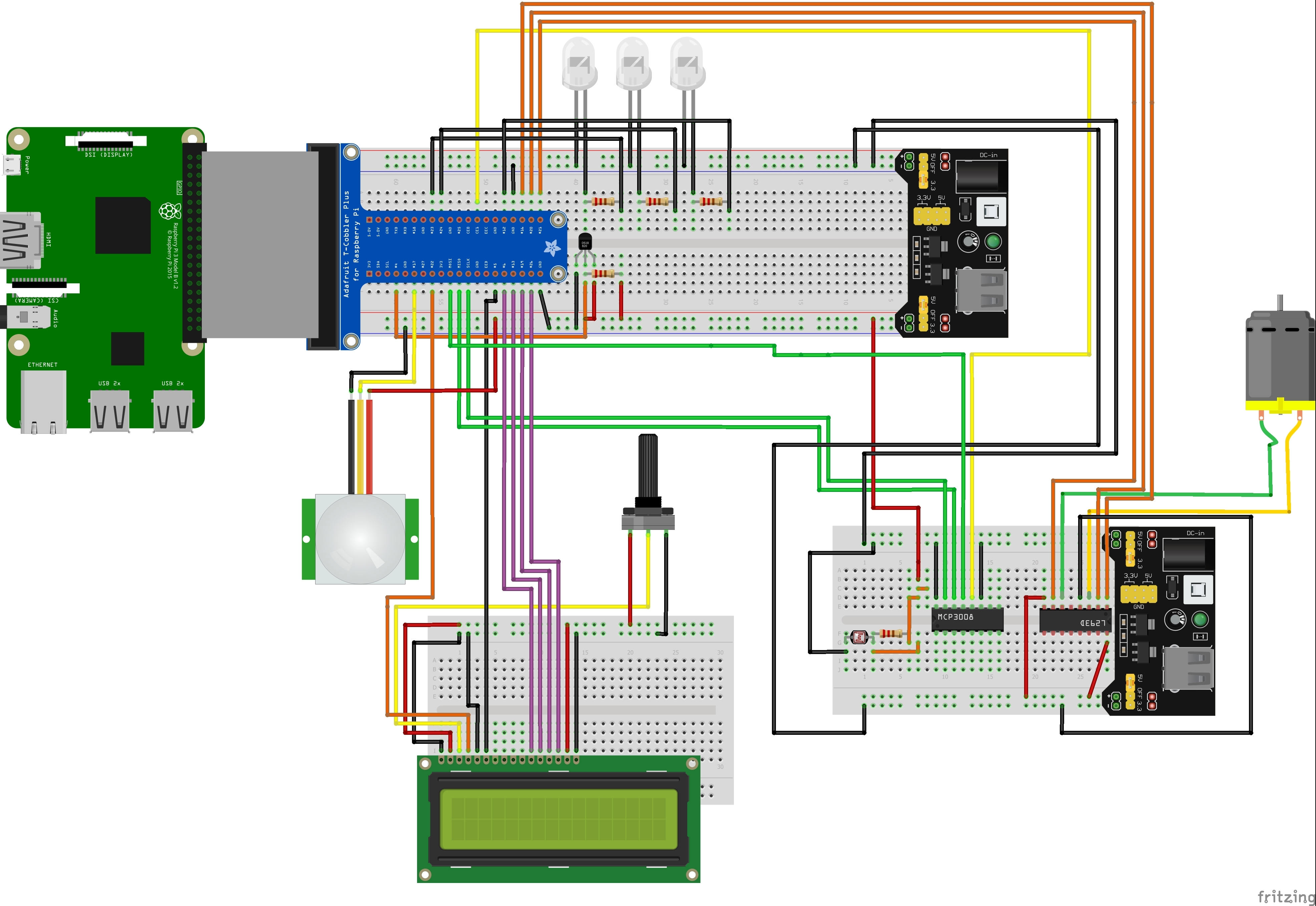
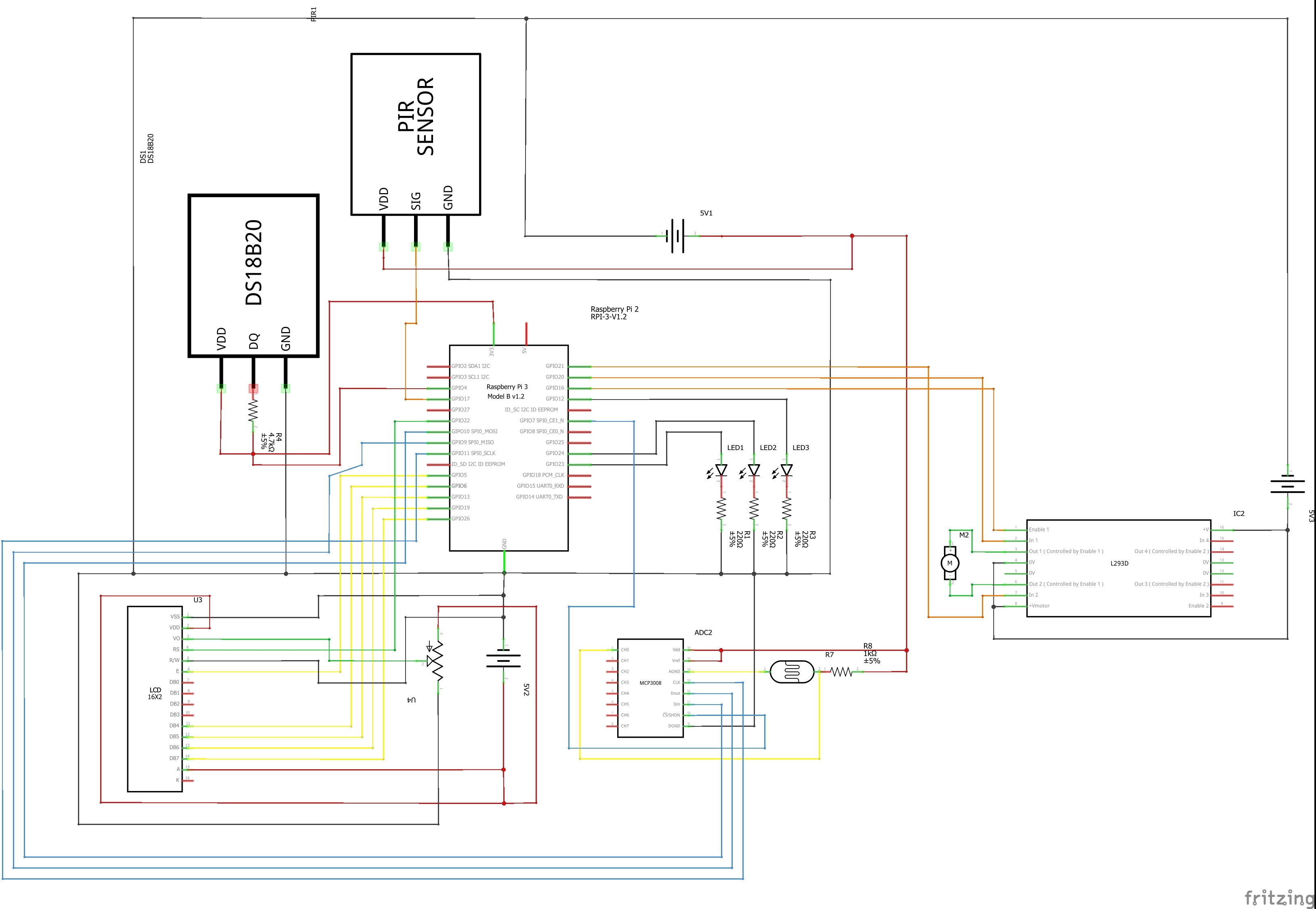
This isn't the smallest electrical circuit but this is what makes this project fun. Try to avoid crossing jumping wires. The wires that don't go to the same breadboard should be longer. You can either solder two wires or connect male to female wires with each other.
Download the Code From Github
You can download the code for this project on my Github, the link is https://github.com/howest-mct/1920-1mct-project1-V... Click on Code and download the backend and frontend.
Make an SSH connection between your PI and Visual Studio Code, if you don't know how, here is a little tutorial. https://code.visualstudio.com/remote-tutorials/ssh...
In VS Code, create a new folder and call it whatever you want, seriously, it doesn't matter. Paste all the files from the Backend in that folder. Part one done. Now navigate to /var/www/ on VC Code and paste the frontend files in there. The coding part is now done!
Create the MySQL Database
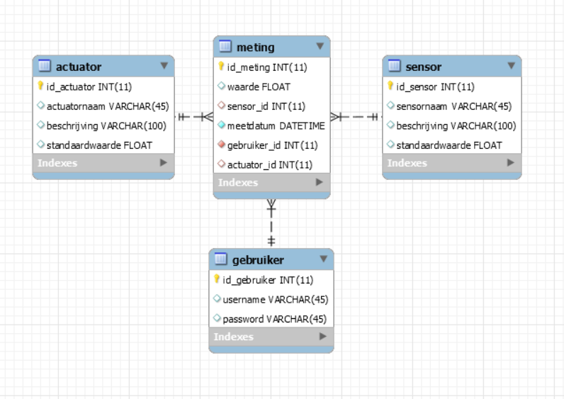
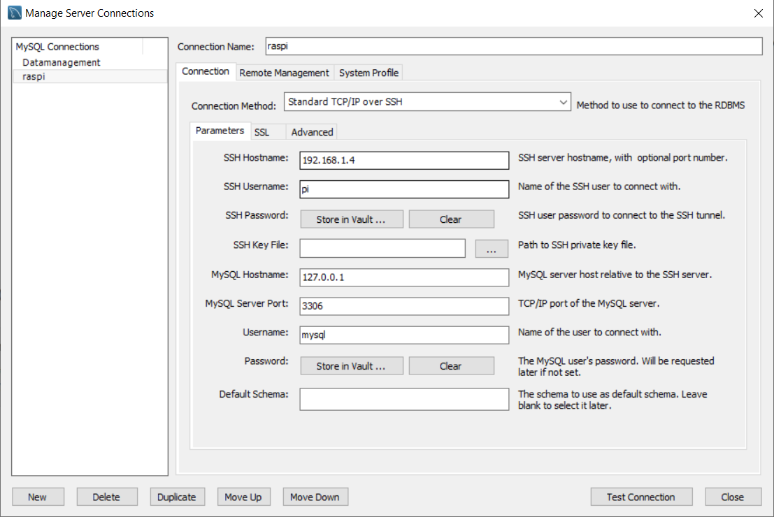
The program I use for creating databases is MySQL Workbench. You can find the download link here. https://dev.mysql.com/downloads/workbench/
Create a wireless connection, refer to my settings, make sure that the SSH hostname is the IP address of your RPi.
Now go to the icon under File in the top left of the screen, click on it, it should open a plain SQL File. paste the smartroomdb.txt code in there and run it (the yellow lightning bolt). Now you are golden!
Downloads
Testing the Smartroom
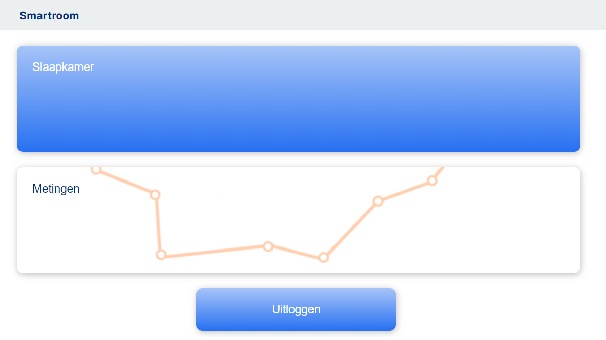
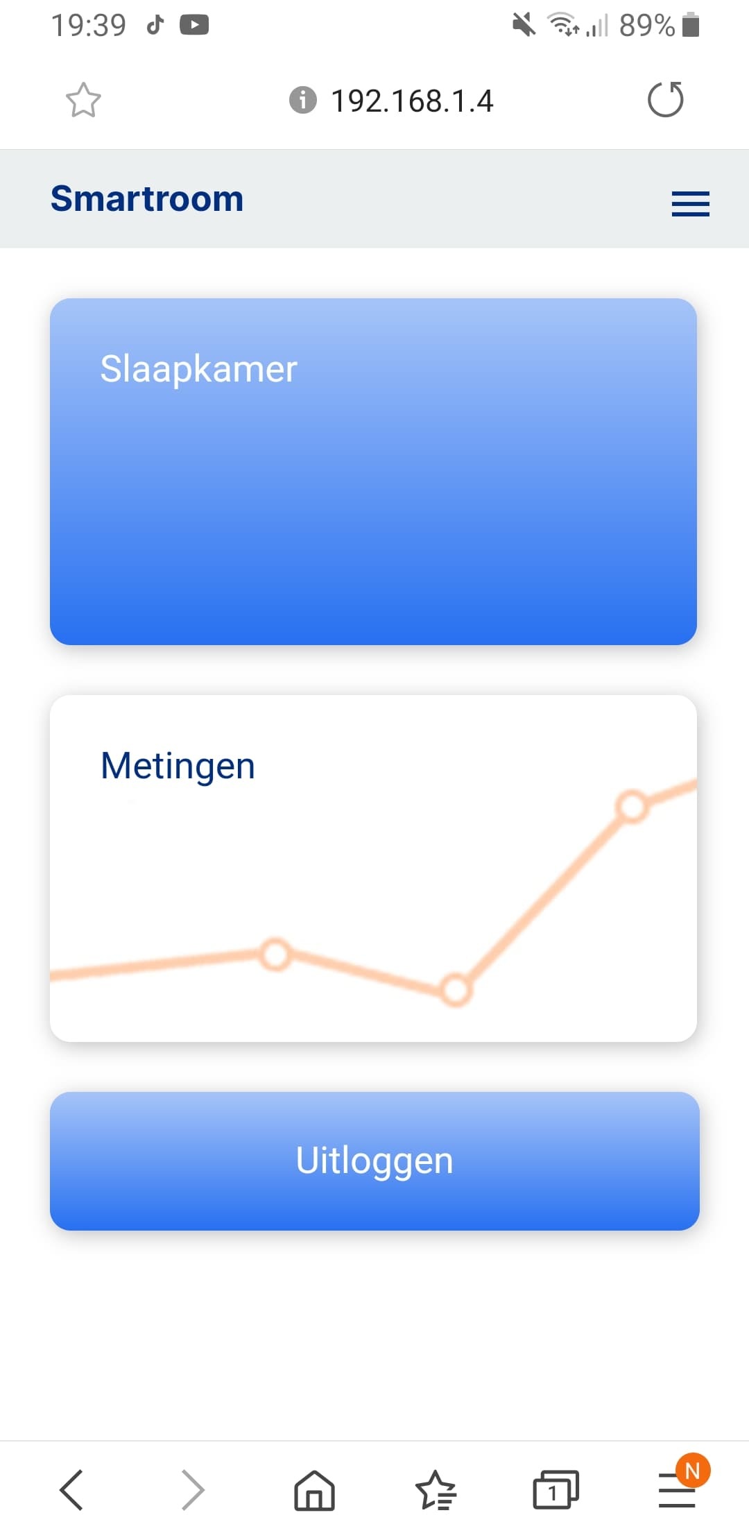
Now that most of the technical parts are done, go to your just created folder in VS Code and start the app.py. There is a little starting icon on the top right corner. Now go to your browser and type in your RPi's IP address. You should see the site.
This website is created mobile first! So yes you can use this project on your phone. Just type in your RPi's IP address.
You can also let the project start when your Raspberry Pi starts. If you want to do this you will have to create a service of app1.py. Follow this tutorial https://www.raspberrypi.org/documentation/linux/u...
You will have to change main.py to app1.py and change the directory to the directory where app1.py is located. Test if everything works in the electrical circuit. If so, move on to the next step!
Putting the Circuit Inside Your Housing
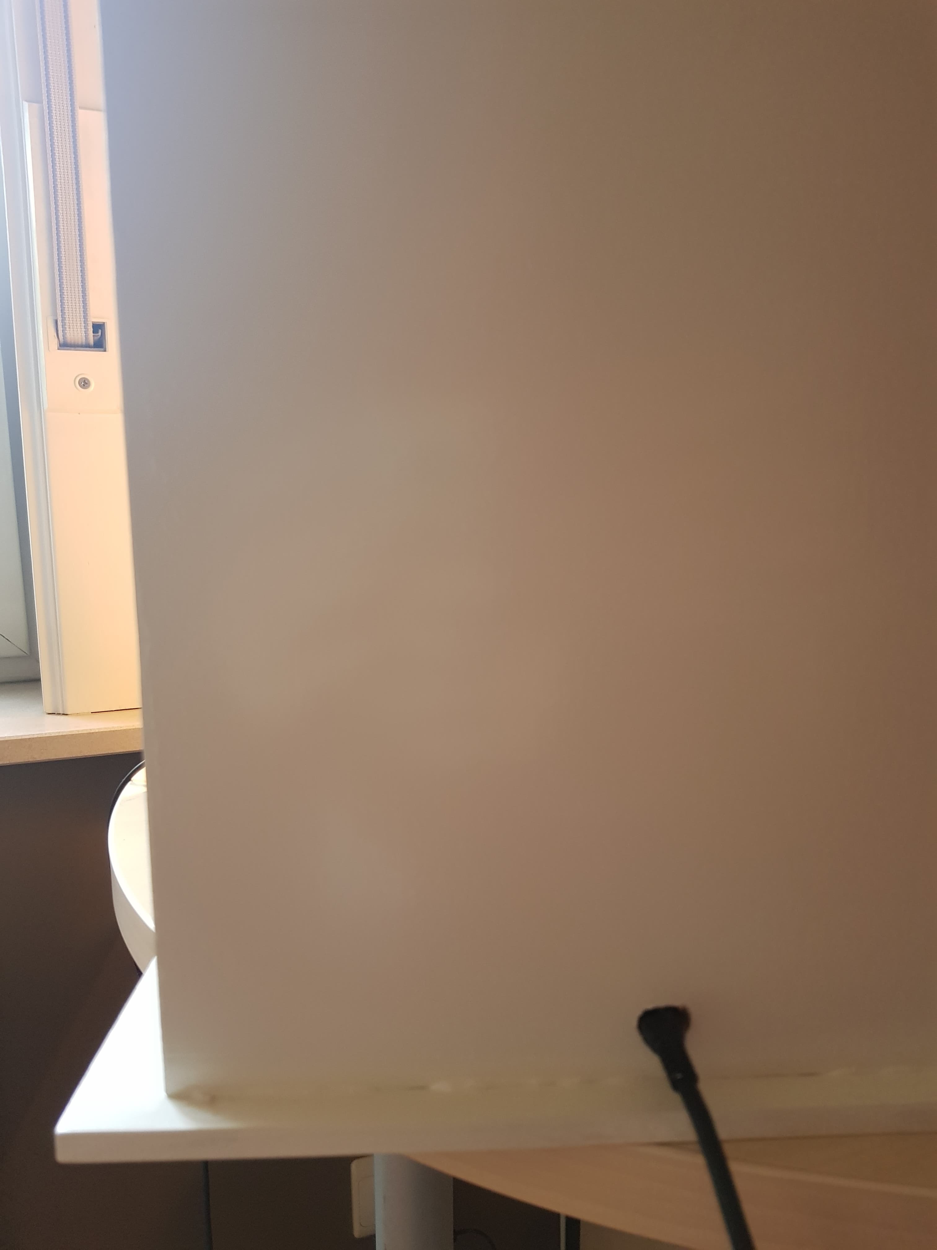
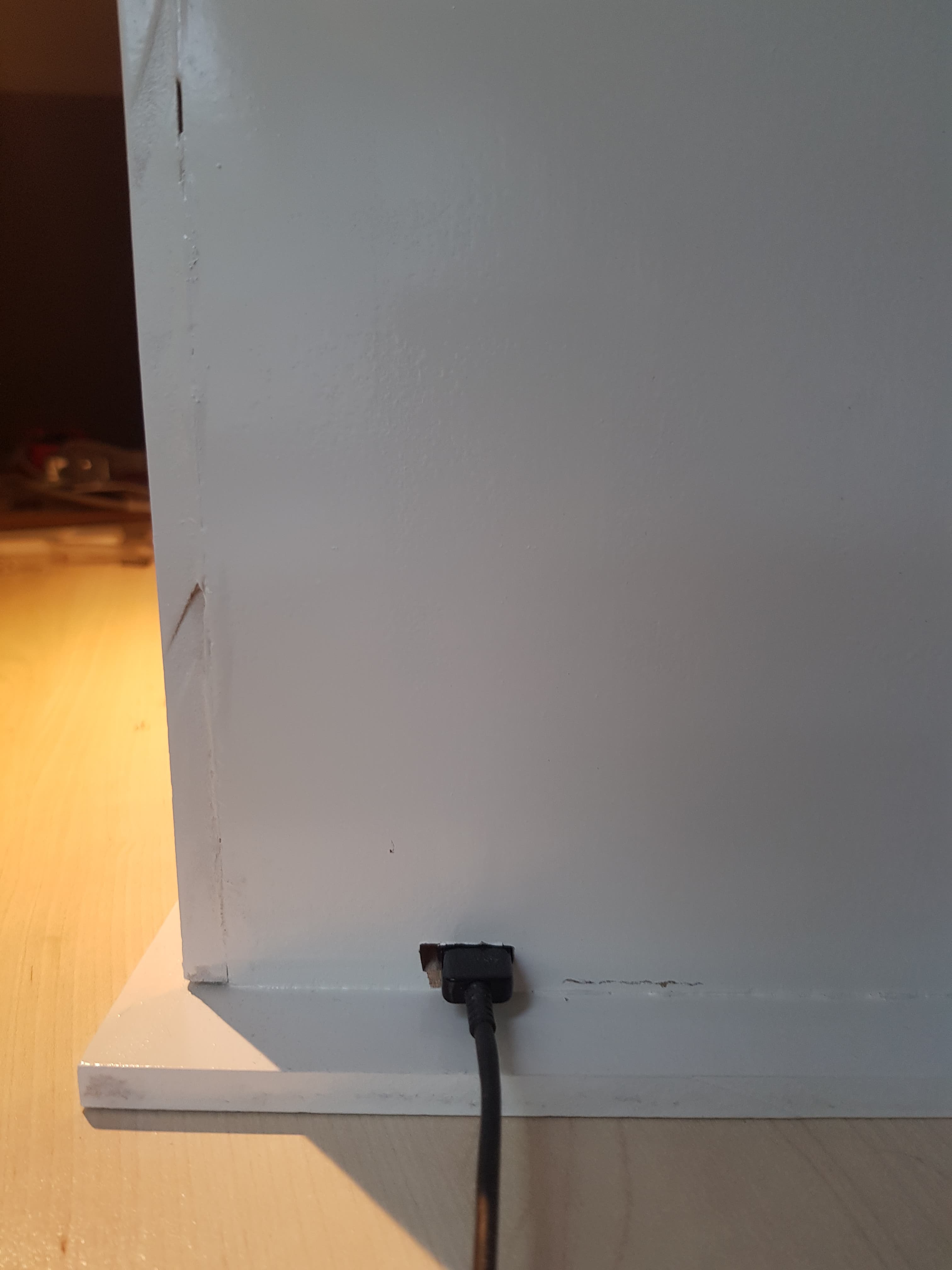
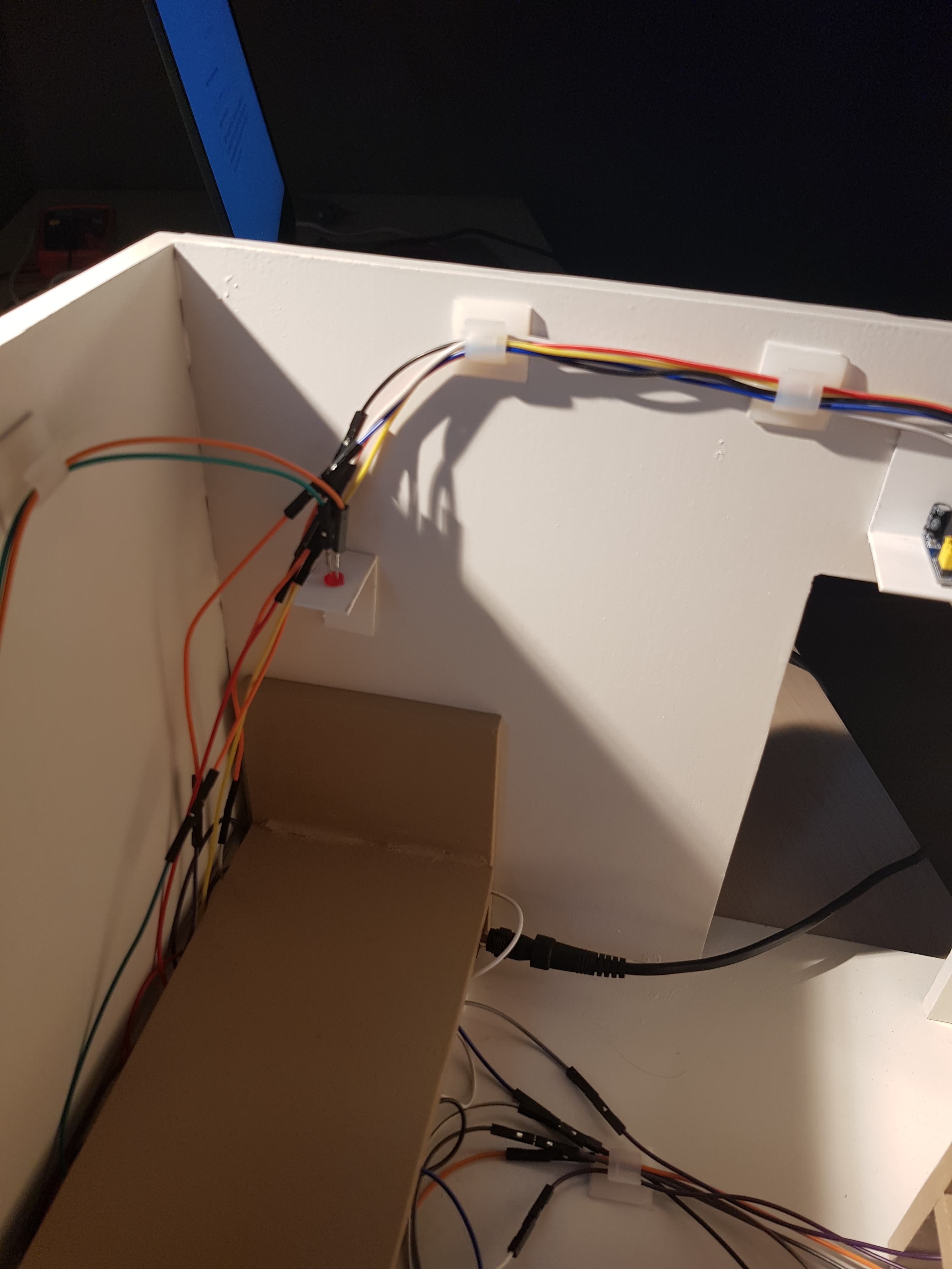
You have reached the last part, congratulations!
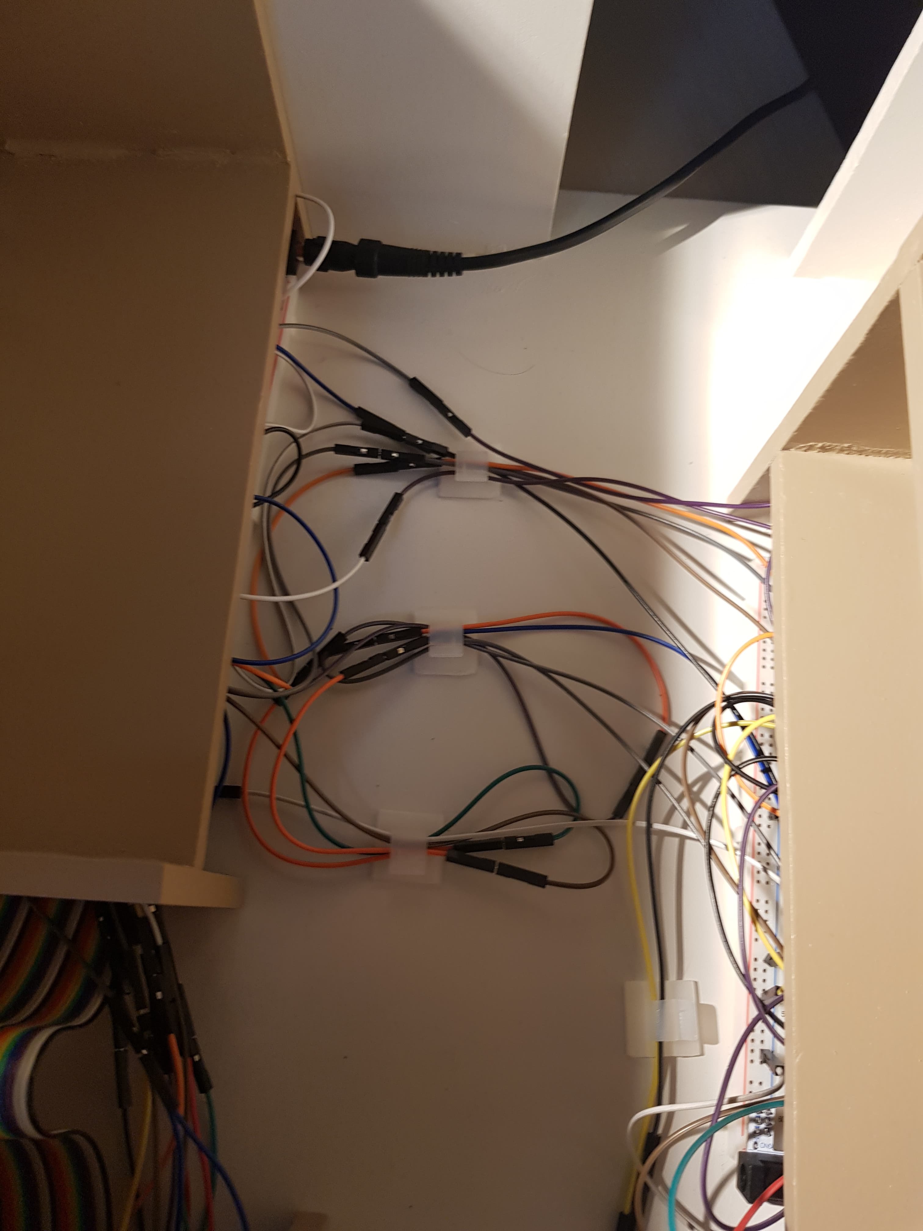
Two holes will need to be drilled in the walls. One where the dressing is and one underneath the desk. You can use a regular drill for that. After that the breadboard with the MCP3008 and the L293D go underneath the dresser and the other breadboard goes underneath the bed. Cable management is up to you. I used a couple of sticky pads that I found in my local DIY store (Hubo).
Enjoy the Smartroom!
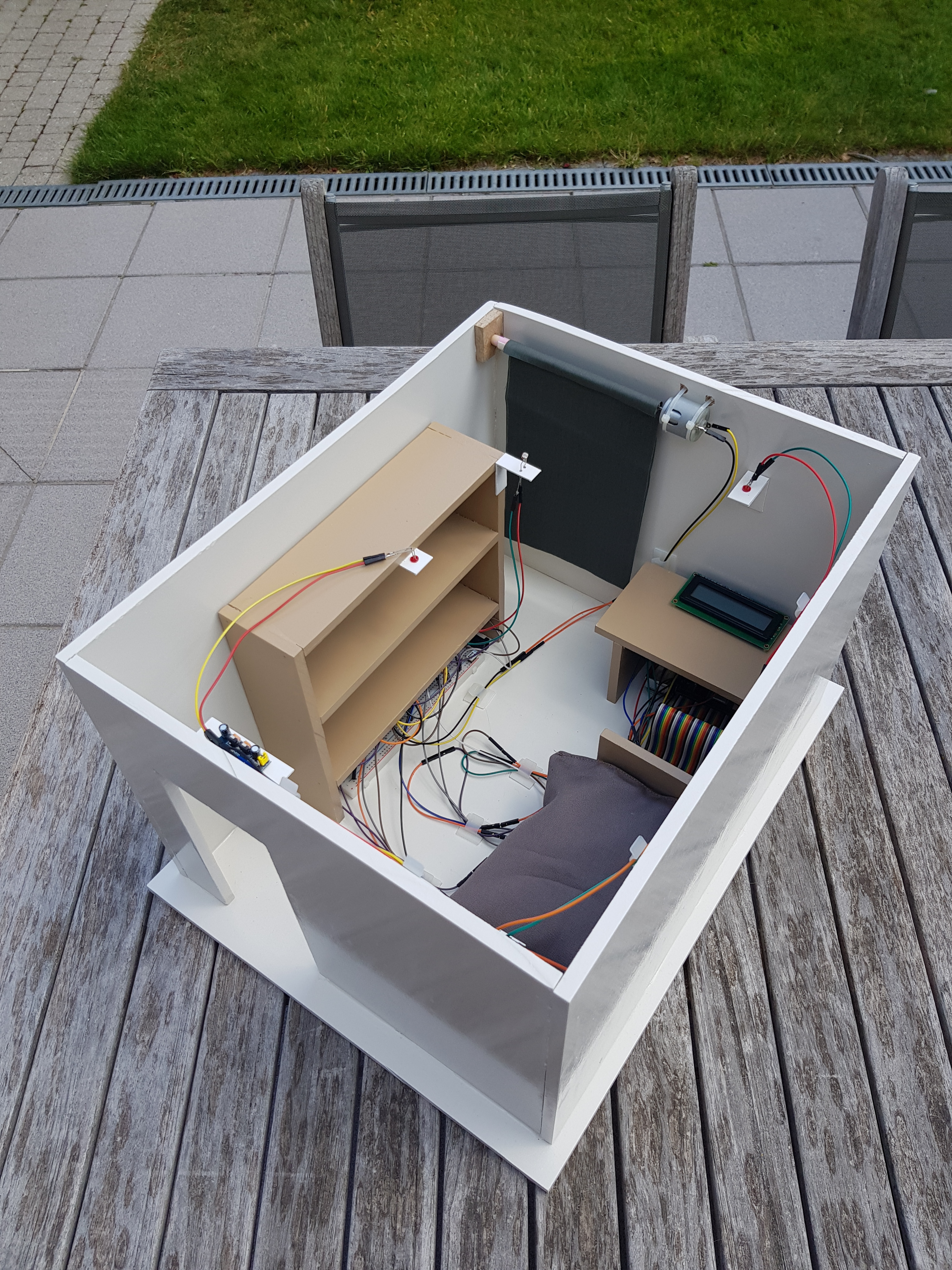
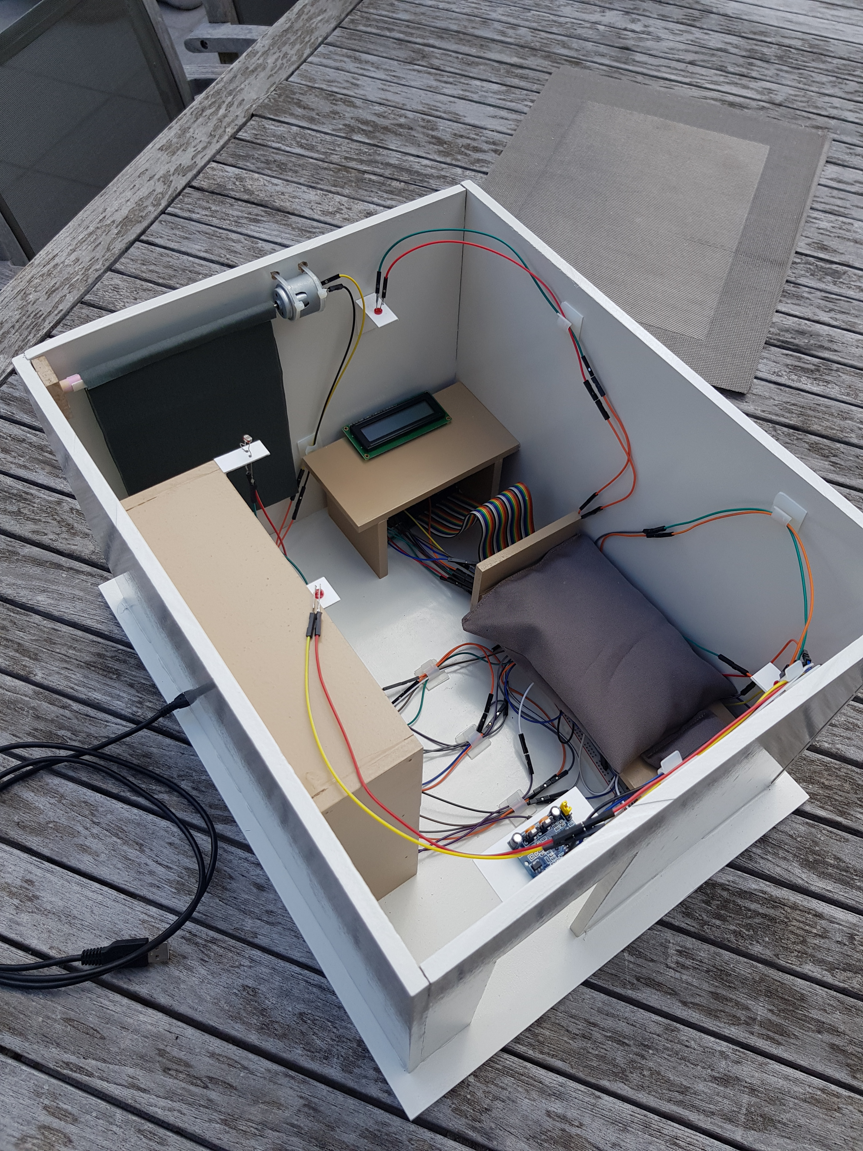
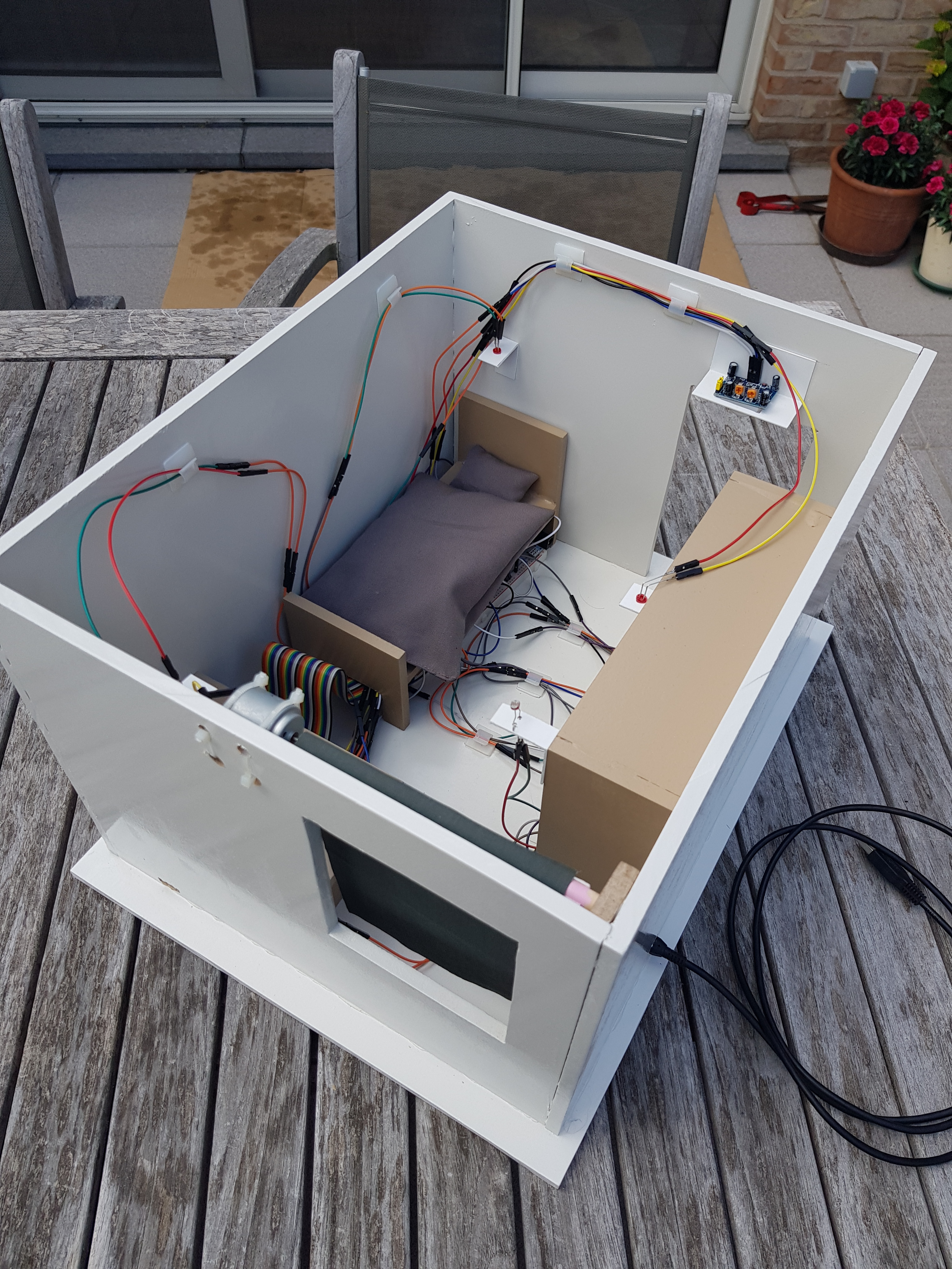
You are now fully set up to use the smartroom, no more getting up to open your shutters!