Make 3D Printed Humanoid Robot and Control It With Smartphone Using Evive- Arduino Based Embedded Platform
by theSTEMpedia in Circuits > Robots
14505 Views, 76 Favorites, 0 Comments
Make 3D Printed Humanoid Robot and Control It With Smartphone Using Evive- Arduino Based Embedded Platform
![[Royalty Free Music] Oceanside — Scandinavianz.00_14_16_03.Still001.jpg](/proxy/?url=https://content.instructables.com/FTT/FVEB/JVMNPK87/FTTFVEBJVMNPK87.jpg&filename=[Royalty Free Music] Oceanside — Scandinavianz.00_14_16_03.Still001.jpg)

Many of you must be knowing who Sophia, iCub, and Atlas are. You must also have dreamt of making something like them for yourself. Well, guess what! Wishes do come true! ;)
Today, we’re going to show you how to make a humanoid robot that can turn his head, look around, and move around. And all it will take are some 3D printed parts, motors, servos and other such components from the evive Starter kit, a Smartphone to control the robot, and loads of DIYing! We’re using Dabble, a versatile project-making Smartphone app, to control the robot and PictoBlox, powerful visual programming software to write the code.
You can get Dabble on Google Play and download PictoBlox from HERE. So, ready for some exciting robot making?
Let’s begin!
List of Components
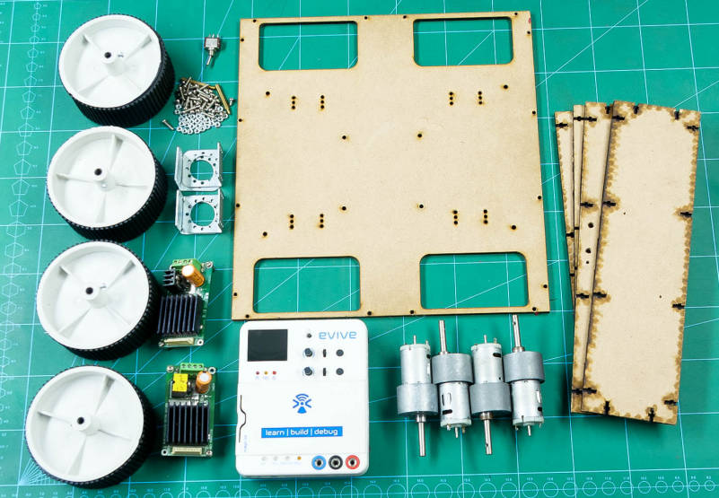
Hardware
- evive
- Metal Servo and Accessories
- Micro Servo and Accessories
- Hercules Motor Driver
- HC05 Bluetooth Module
- High Torque Motor
- Tracked Wheel
- Slide Switch
- Lithium Polymer Battery
- M3 Bolts of 8mm Length
- M3 Bolts of 20mm Length
- M3 Nuts
- M4 Lock Nuts
- Jumper Wires
Software
We've listed down electronic and mechanical components only, but you will require to get a few parts laser cut and 3D printed, design files for which are available here and here, respectively.
Note - STL files available on the link are designed by InMoov.
Downloads
Process Overview
![[Royalty Free Music] Oceanside — Scandinavianz.00_14_16_03.Still001.jpg](/proxy/?url=https://content.instructables.com/FU8/SO56/JVMNP4YN/FU8SO56JVMNP4YN.jpg&filename=[Royalty Free Music] Oceanside — Scandinavianz.00_14_16_03.Still001.jpg)
We can divide the making of the Humanoid Robot into 3 steps:
- Assembling the Humanoid Head
- Making of the 4-Wheel Drive
- Combining them together
Assembling the Humanoid Head

This step is further divided into the following sub-steps:
- Fixing the Holder
- Assembling the Throat
- Fixing of the Neck Servo (HS-805BB servo)
- Assembling the Jaw
- Assembling the Back Skull
- Assembling the Head
- Attaching the Eye Mechanism
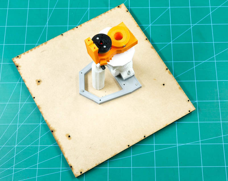
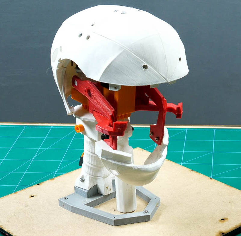
Fixing the Holder
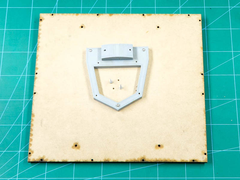
We will fix the head of the robot on the MDF base plate or chassis whose design can be found from the PDF attached from Step-1.
Fix the 3D printed holder in the center of the MDF sheet using M3 nuts and bolts of 25mm.
Finally, screw M3 nuts and bolts of 20mm length in the center holes.
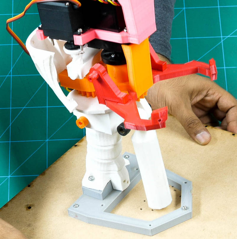
Assembling the Throat
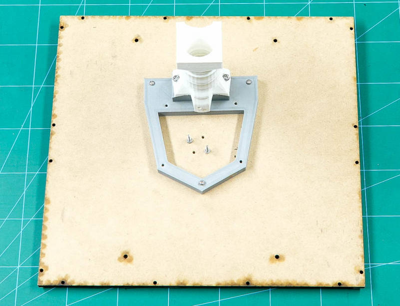
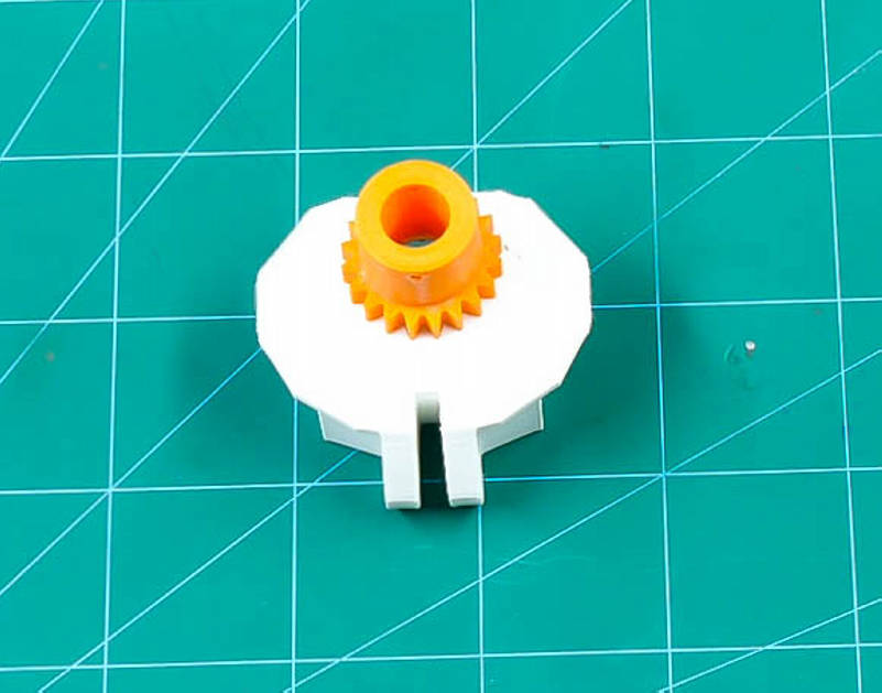
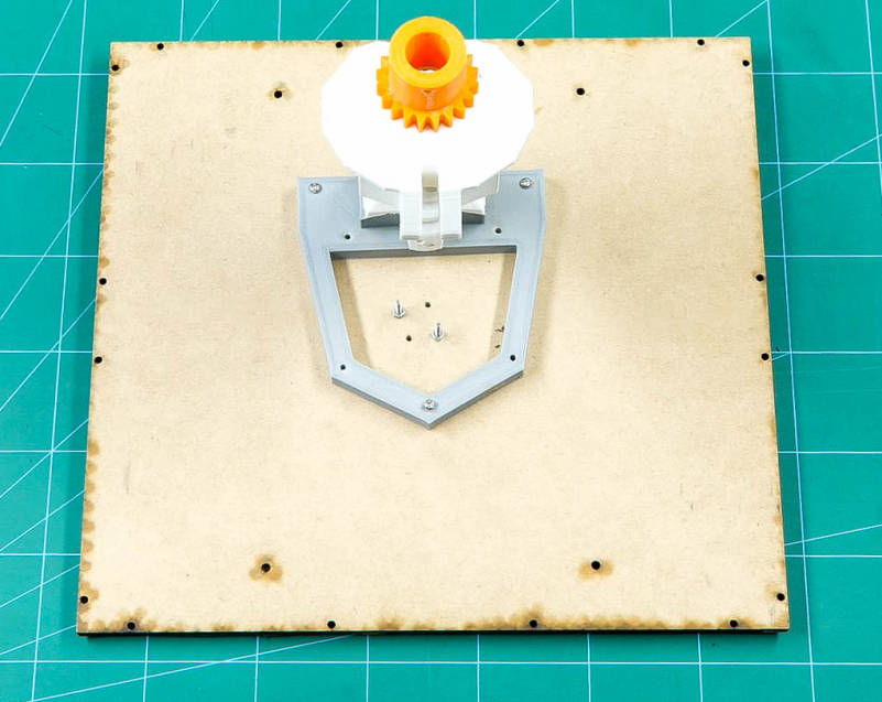
Fix the ThroatHole on the 3D printed holder attached on the chassis using M4 bolts.
Attach the MainGear to the NeckHinge using M4 bolts and fix it on the ThroatHole using a 3D printed connector.
Take the ThroatPiston, which will act as the support for the entire head and fix it in the NeckHinge using the black 3D printed connector.
We have inserted M3 nuts and bolts free in the center of the chassis in the previous step so that we can fix the ThroatPiston from its hollow space into it.
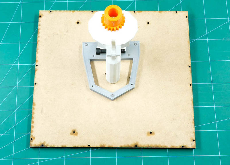
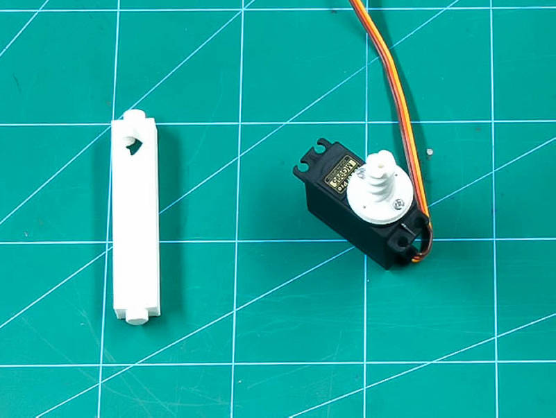
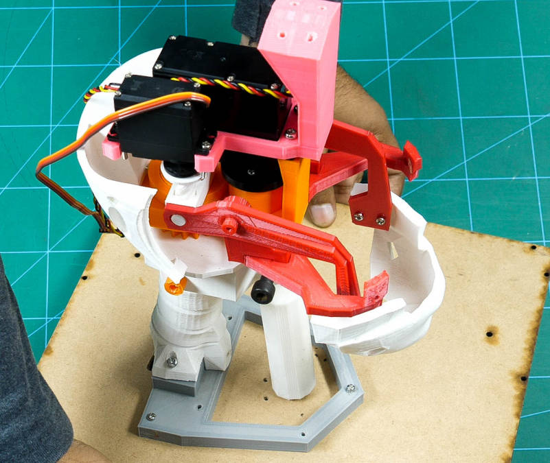
Fixing of the Neck Servo (HS-805BB Servo)
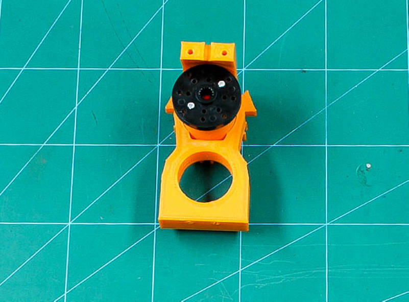
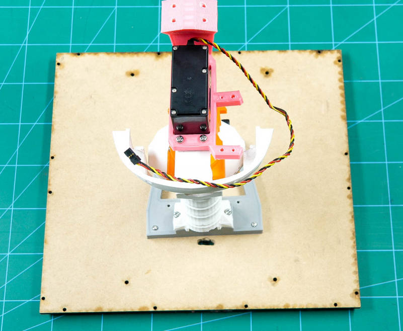
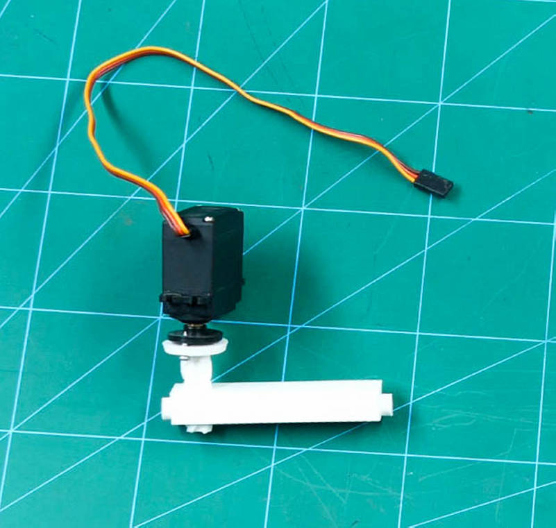
Pass the ServoGear it through the GearHolder and fix actuator wheel to the ServoGear.
Attach GearHolder assembly to the ThroatHole assembly using M4 bolts.
Screw Ring to the MainGear using M3 bolts.
Attach the LowBack(V3) to the GearHolder using M3 bolts.
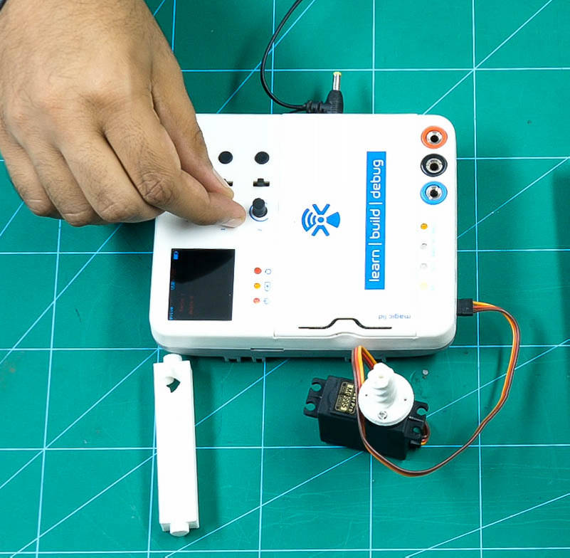
Calibrate the HS-805BB servo(neck servo) using evive's firmware and set the angle to 90º.
Go to evive menu, choose Controls, select Motors, then select Servos, select Servo1, and set the angle using Potentiometer 1.
Attach the servo to the SkullServoFix using M4 bolts and fix the SkullServoFix to the LowBack using M3 nuts and bolts.
Note: Make sure that the servo head fixes in the Rotation wheel.
Once this assembly is done check the rotation of the head using evive’s firmware.
You can get your very own evive from the link given here.
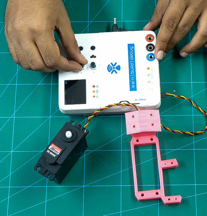
Assembling the Jaw
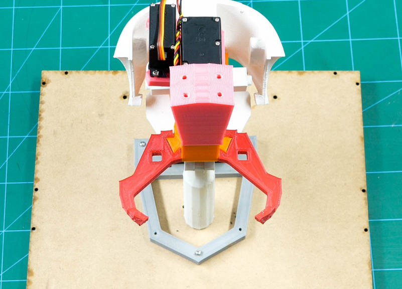
Fix JawPiston to the metal servo using the self-threading screw.
Push the JawHinge through the JawPiston.
Calibrate the metal servo(jaw servo) using evive's firmware an angle such that JawHinge should slip out. For us, we will set the set at 65°
Attach this JawPiston assembly to the SkullServoFix using M3 Nut.
Fix the FaceHolders in the slot given on the GearHolders on both the side.
Fix both the JawHinge(V3) on both the FaceHolders.
Take the Jaw(V4) and fix JawSupport(V1) to it using M3 bolts.
Fix the Jaw assembly to the JawHinge on both sides.
Once done, test the movement of the jaw by connecting the jaw servo to evive and control it using evive’s firmware.
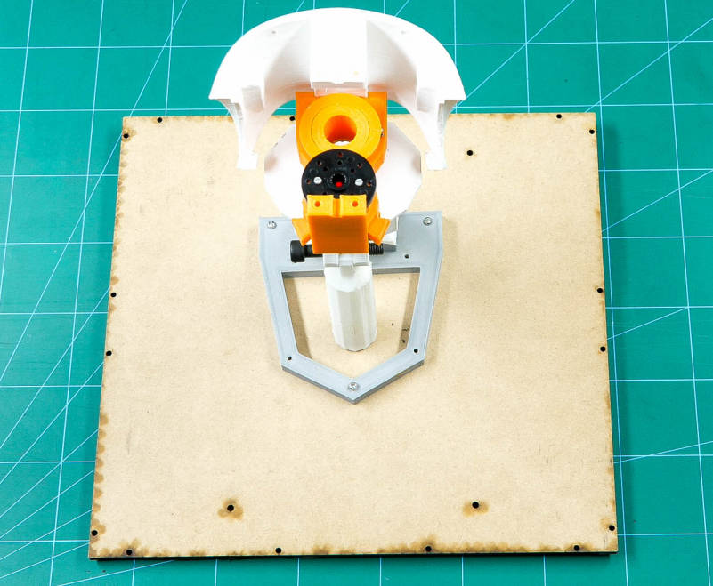
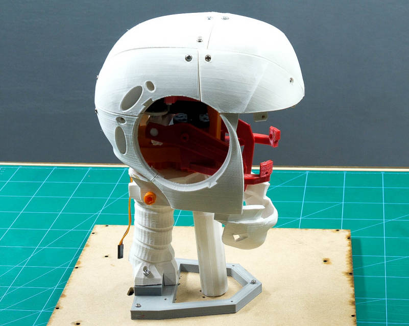
Assembling the Back Skull
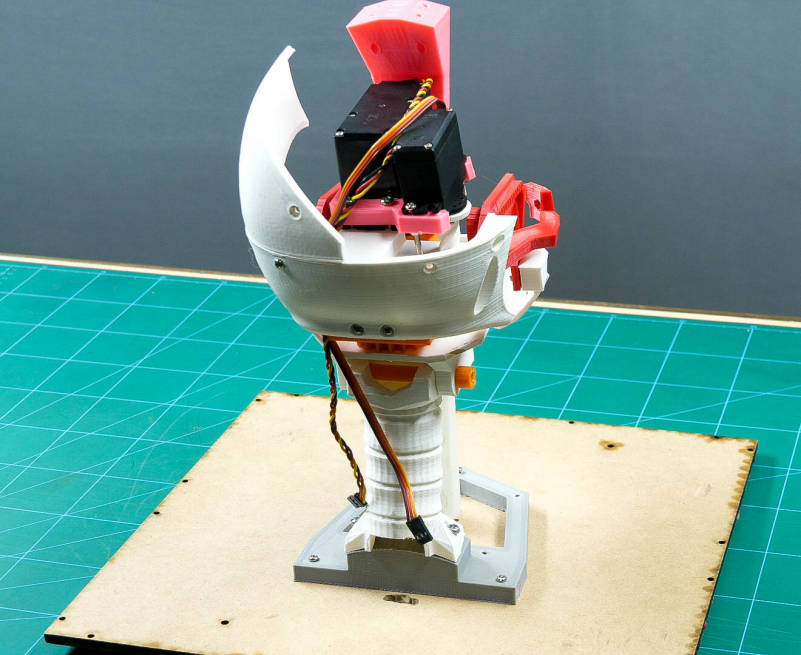
Let's complete the assembly of the skull.
Fix two TopBackSkull(V1) on the LowBack using M3 nuts and bolts.
Fix TopSkullLeft(V3) and TopSkullRight(V3) together using M3 nuts and bolts. Attach these parts to the SkullServoHolder using M3 nuts and bolts.
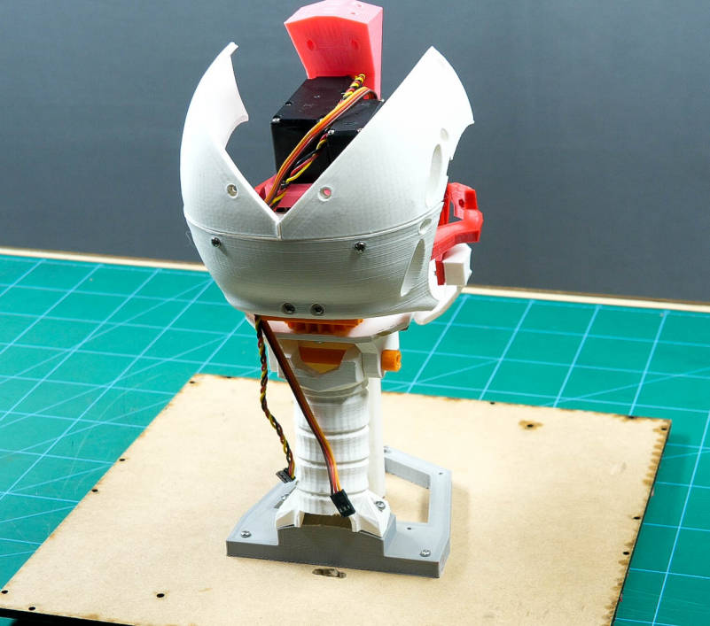
Assembly of the Head
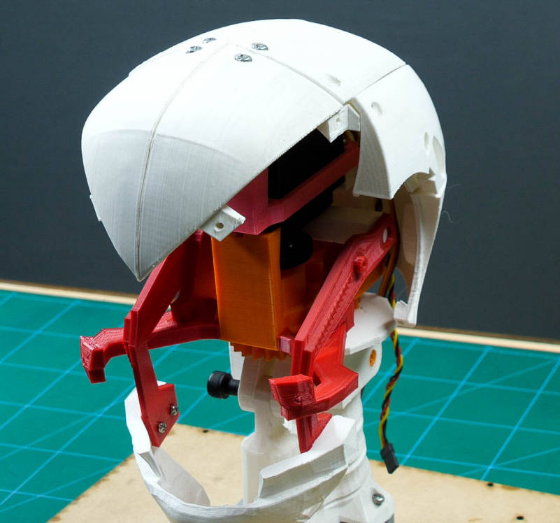
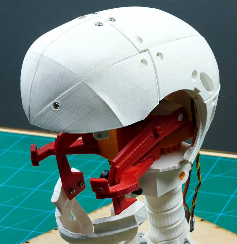
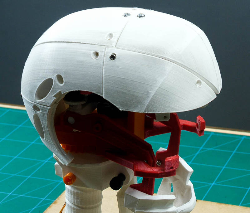
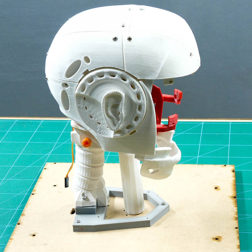
Fix the other TopSkullLeft(V3) and TopSkullRight(V3) and again fix them together as we did for the previous step and fix them to the assembly made.
Again fix the other TopSkullLeft(V3) and TopSkullRight(V3) next to the assembly made using M3 nuts and bolts.
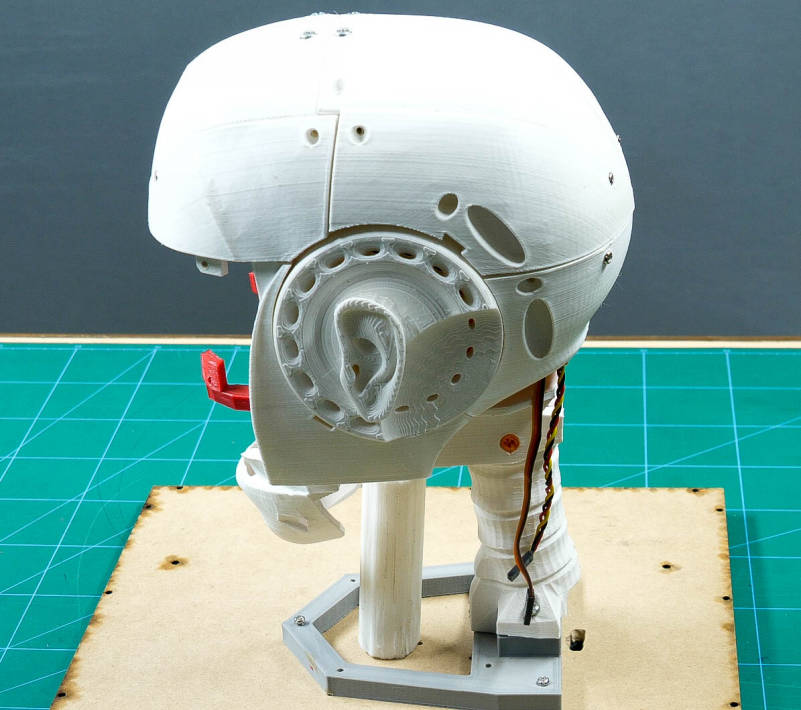
Attach the SideHear(V3) next to the TopSkullRight using M3 nuts and bolts.
Fix the Ear into the SideHear. Repeat on the other side.
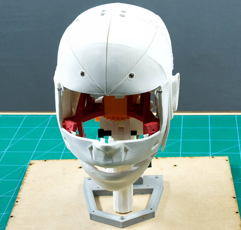
Next, attach the TopMouth(V3) to the TopSkullRight and TopSkullLeft using M3 bolts.
Once done, check the movement of the jaw using evive's firmware. But, this time we will notice that the head seems to talk.
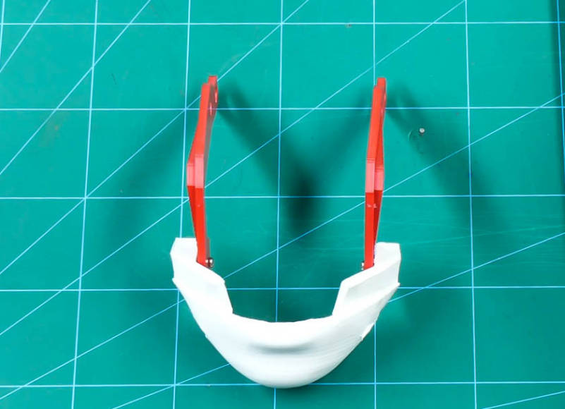
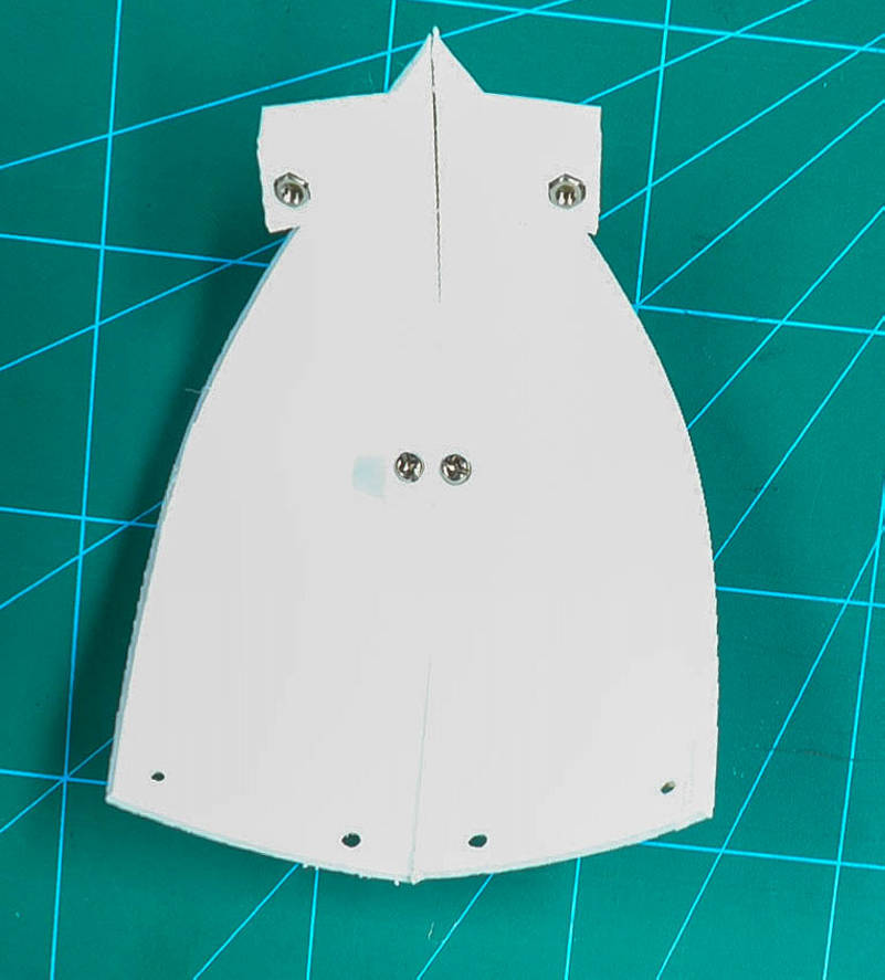
Attaching the Eye Mechanism
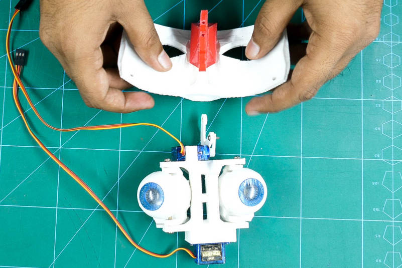
You can find the step-wise procedure of the assembly of the eye-mechanism from InMoov's website.
Once our eye mechanism is ready, fix it to the EyeGlass(V4).
A small slot is given in the Eyeglass to fit the eye mechanism.
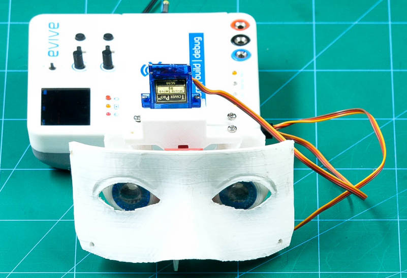
After attaching it, check both the micro servos(one to make horizontal eye movement and the other to make vertical eye movements) using evive's firmware and bring the eyeballs to the center.
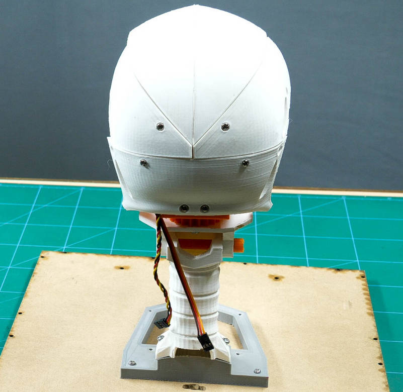
Then, take the TopMouth out of the assembly and fix the EyeGlass to it using M3 nuts and bolts.
Finally, fix this assembly in the head.
Yay! The Humanoid Head is now ready.
Making of 4-Wheel Drive (Attaching Motors to the Chassis)
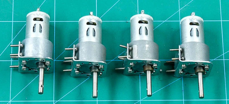
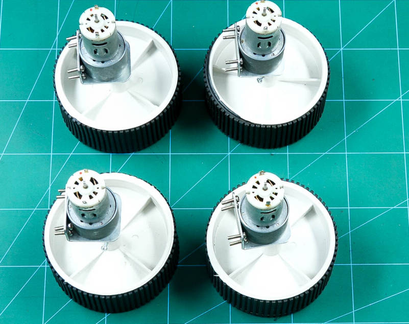
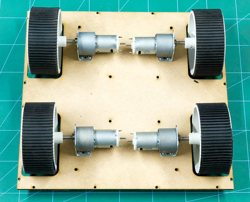
Insert 12mm screws to the motor brackets to attach 100rpm DC Motors to it.
Fix wheels to the motor shafts using screws.
Attach the wheels to the motor brackets using the M3 nuts and bolts.
Making of 4-Wheel Drive (Adding the Motor Drivers)
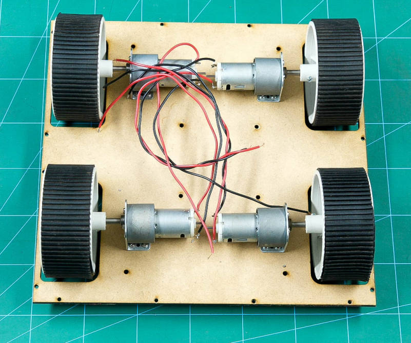
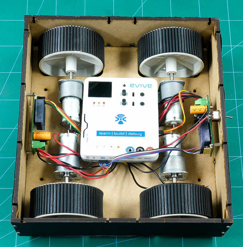
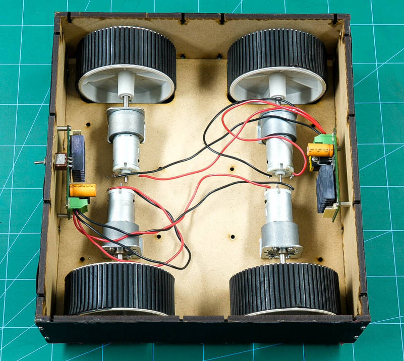
All we need to do now is to attach wires to the motors.
Solder the connecting wires to the motors.
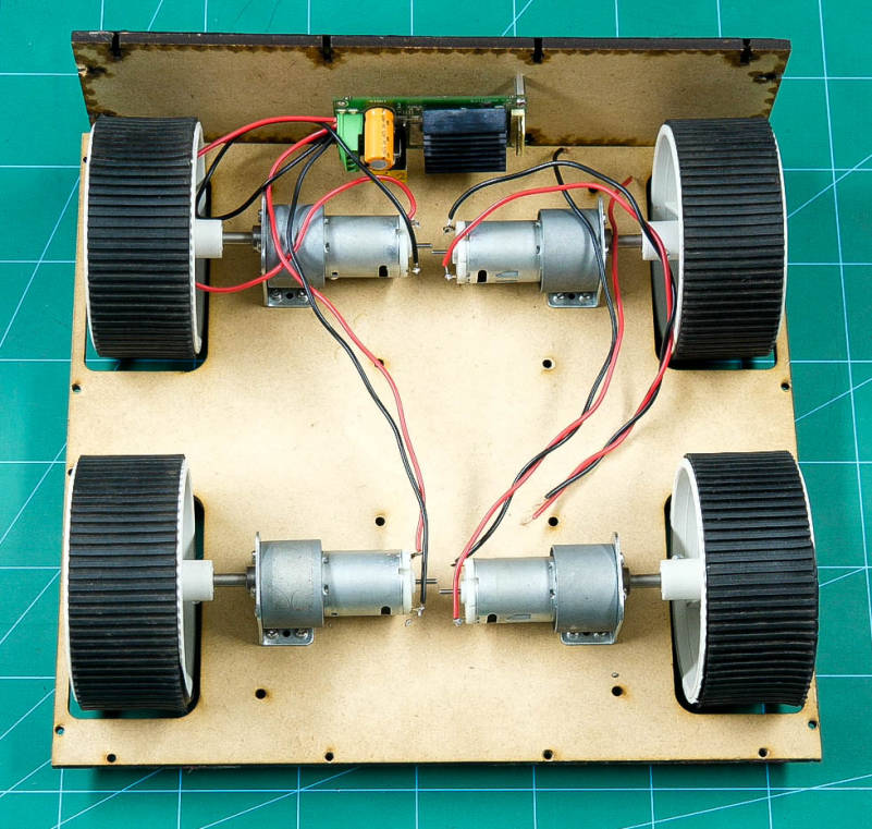
Attach the motor driver to the side wall using M3 nuts and bolts which in turn is attached to the chassis using M3 nuts and blots.
Connect the wires of the motors of one side to this motor driver.
Likewise, complete the other wall.
Once done, fix the front and the back walls.
To power up the robot attach a slide switch to one of the walls.
Connect motors of each side parallelly.
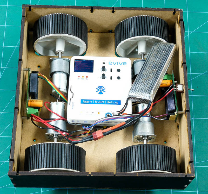
Now connect the motor drivers and battery to evive.
Before uploading the final code to evive. Test the motors using evive’s firmware.
Once done, upload the code to evive.
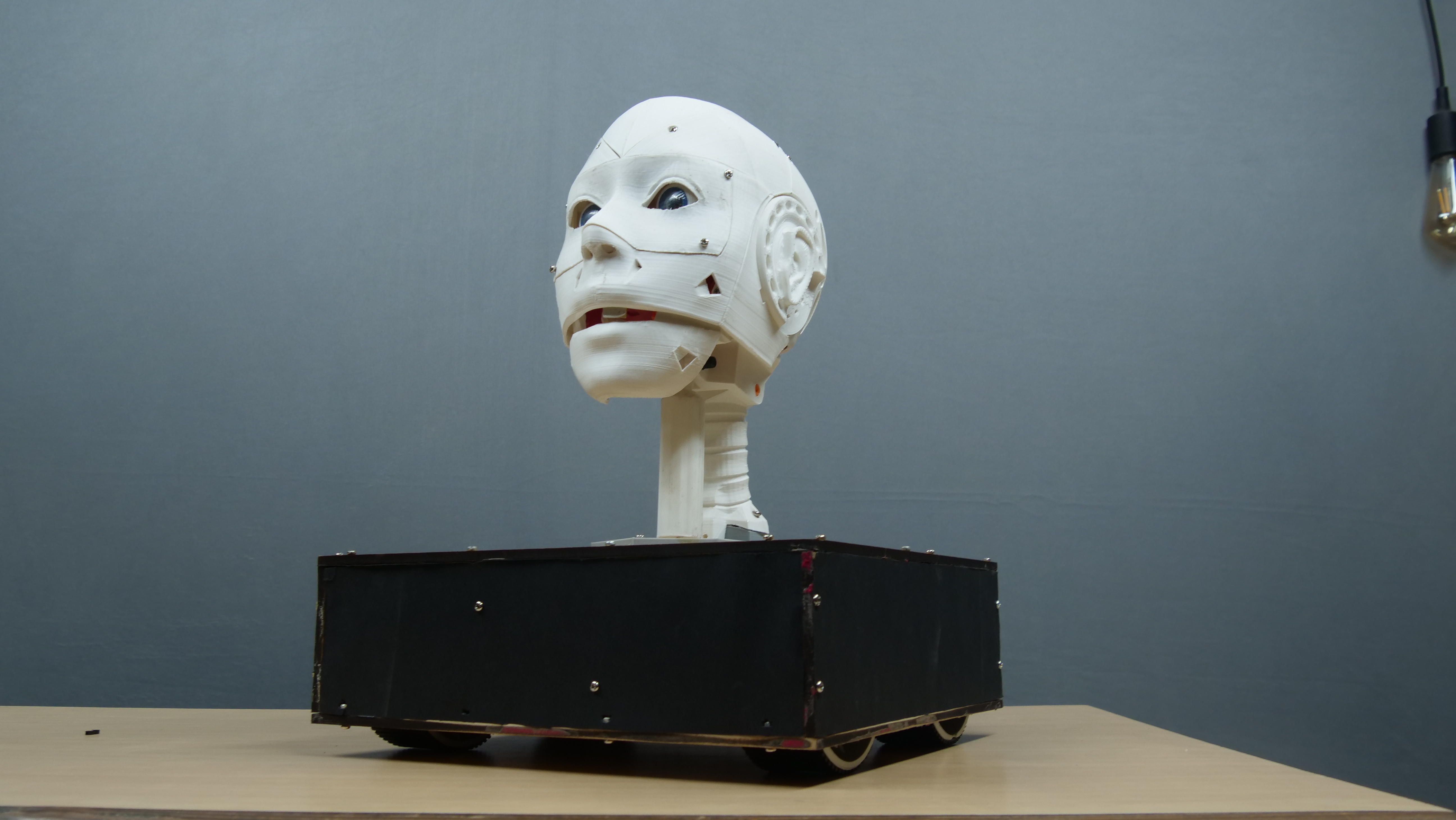
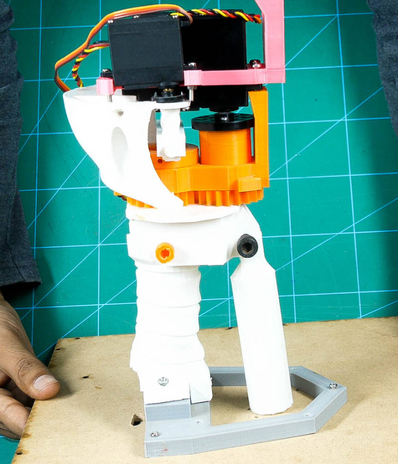
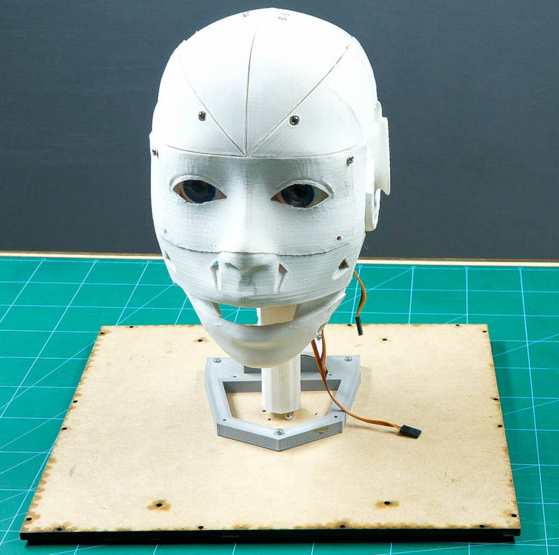
Combining the Assemblies
![[Royalty Free Music] Oceanside — Scandinavianz.00_14_16_03.Still001.jpg](/proxy/?url=https://content.instructables.com/F3Q/VAAI/JVMNPIJN/F3QVAAIJVMNPIJN.jpg&filename=[Royalty Free Music] Oceanside — Scandinavianz.00_14_16_03.Still001.jpg)
Bring the Humanoid robot head and connect all the servos to evive as given in the circuit diagram section.
Fix the head on chassis using M3 bolts and nuts.
Thus, your humanoid robot is now ready.
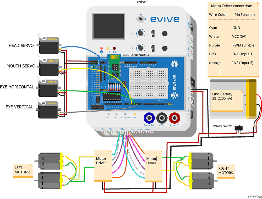
Circuit Diagram
Connect Motors to the Motor Drivers
- Connect both the motors of the left side in parallel.
- Connect both the motors of the right side in parallel.
- Connect one end of the left motor to one of the motor output terminals(OUTA1) of left motor driver.
- Now connect the other end of the motor to motor output terminal (OUTA2) of the left motor driver.
- Similarly, connect the right side.
- Now connect the VCC and GND of both the motor drivers together.
- Take the slide switch and connect its one end to the positive terminal of the battery and its other end to VCC terminal of the motor driver.
- Connect the negative terminal of the battery to the GND terminal of the motor driver.
Connect Bluetooth with evive
- Connect HC-05 Bluetooth module in the given place
Connection of Motor Drivers with evive
- Connect the positive and negative terminal of a battery to the VIN port on the evive.
- Connect VCC, GND, PWM, IN1, and IN2 pins of the left motor driver to MD1 port on evive as shown in the figure.
- Similarly, connect VCC, GND, PWM, IN1, and IN2 pins of the right motor driver to MD2 port on evive.
Finally, connect the face servos with evive
- Connect (HS-805BB Servo or Head Servo) Signal pin to pin number 2 of evive
- Connect (Metal Servo or Mouth Servo) Signal pin to pin number 3 of evive
- Connect (micro Servo or eye Horizontal Servo) Signal pin to pin number 4 of evive
- Connect (micro Servo or eye Vertical Servo) Signal pin to pin number 5 of evive
- Connect the VCC and GND of all the servo motor together and connect it to the VCC and GND of evive respectively.
Working of the Humanoid Robot
Connect the Humanoid Robot to Dabble via HC-05 Bluetooth module. You can control almost all the boards like Arduino Mega, Nano, Uno, ESP32, and evive using Dabble. Open Dabble and click on the Connect-Disconnect button. Choose your device’s name from the list.
We are using two modules together:
- Accelerometer (Phone Sensors)
- Input Module
Accelerometer
The accelerometer is used to control the DC Motors which is responsible for the movement of the robot.
Open Phone Sensors click on the toggling button next to the Accelerometer. This will start sending data to evive. When we tilt the phone either forward or backward, acceleration along the X-axis changes.
- If the acceleration along X-axis goes above 6 m/s2, then the robot will move in the forward direction.
- If it goes below -5 m/s2, then the robot moves in the backward direction.
- If we tilt the phone either left or right, acceleration along with the Y-axis changes.
- If the acceleration along Y-axis goes above 6 m/s2, then the robot moves in the left direction.
- If goes below -5 m/s2, then the robot will move in the right direction.
- If the acceleration along both the axes i.e X-axis and the Y-axis is between -6 m/s2 and 6 m/s2, then robot does not move.
Input Module
The HS-805BB servo is used to control the movement of the head i.e. from right to left and vice-versa. We can control it from the Potentiometer 1 of the Input Module.
The metal servo is used to control the movement of the Jaw. We can open and close the jaw using the Tactile switches of the Input Module.
- Tactile switch 1 is used to open the jaw for a longer duration.
- Tactile switch 2 is used to open the jaw for a shorter duration.
The two micro servos are attached in the eye mechanism. They can be controlled using the Slide switches of the Input Module.
- Slide Switch 1 is used for the horizontal movement of the eye i.e. left and right.
- Slide Switch 2 is used for the vertical movement of the eye i.e. up and down.
Want to know more about Dabble, visit here.
Code the Robot
We are going to use PictoBlox to code the Humanoid Robot. Upload the following script to evive:


To know more about PictoBlox, visit here.
Downloads
Conclusion
With this, your humanoid robot is all set to move around and explore the world with you!