SmartFridge
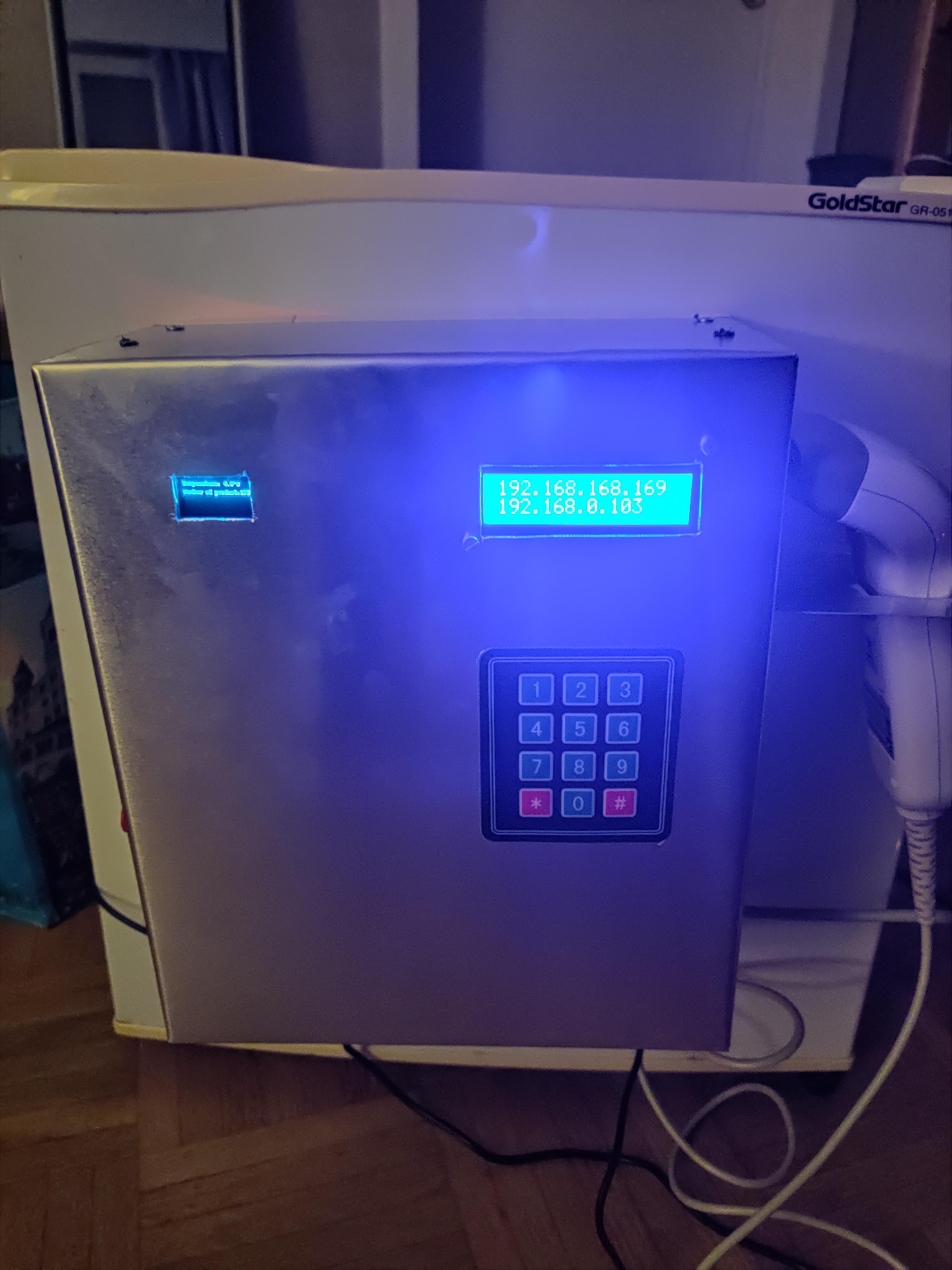
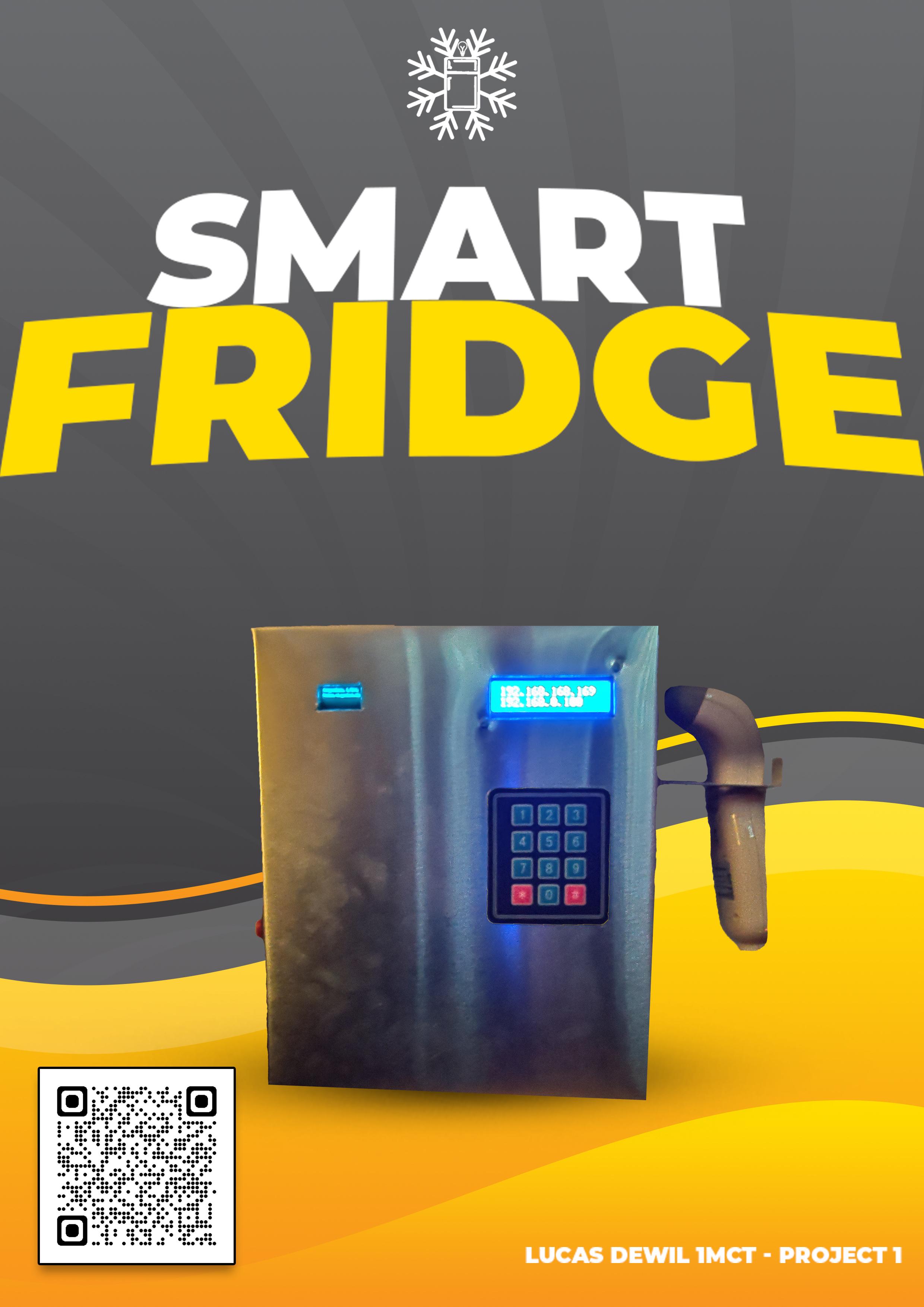
As a student, I often had the problem that too much food went to the bin because I didn't really have an inventory of what was in my fridge.
Which is a big issue because I, as a student, do not have much money to buy food every time.
The environment is also something that is very important to me, did you know that a third to half of all the food produced is lost or wasted and causes about 8% of global greenhouse gas emissions?
At the end of this project, I want to have achieved the following:
- I want to see what I should eat first
- Be able to follow up on an inventory remotely
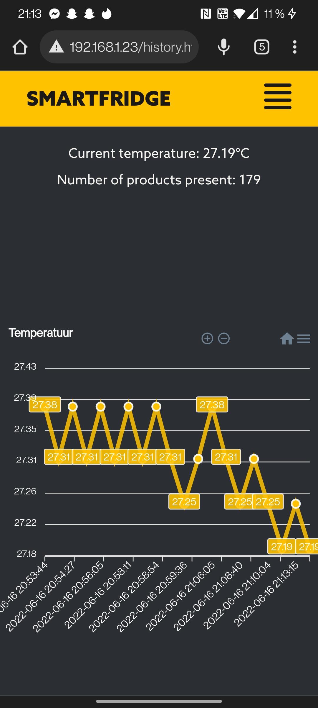
- Monitor the current temperature, so I can see if it is too high (or too low) for my food
- Get a notification of what is already past due and what is about to go past due
- I want to see when the fridge is open
I am sharing this instructable with you so that you too can easily do your bit to preserve our environment and make your bills smaller. (And secretly for the smell of food that has been sitting in your fridge for a long time ;))
Supplies
.jpg)
.jpg)
.jpg)
.jpg)
.jpg)

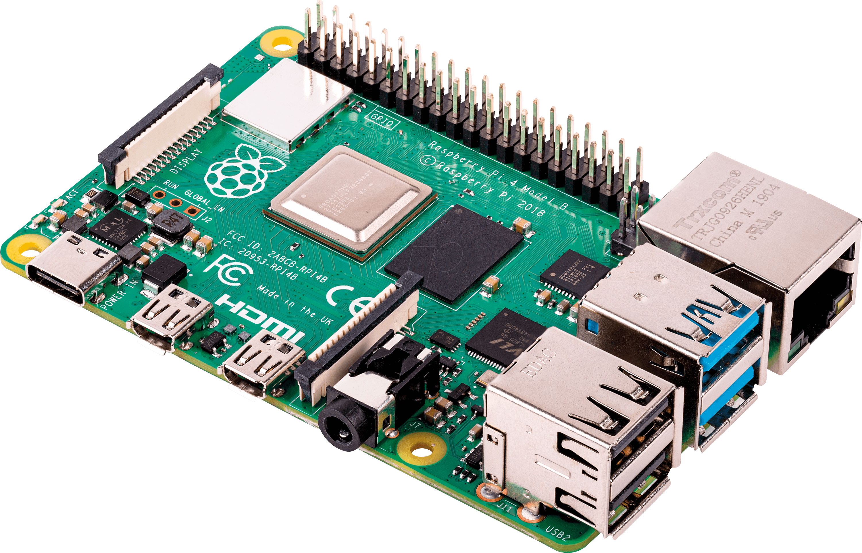
Main computing unit:
This is the main controller of the system.
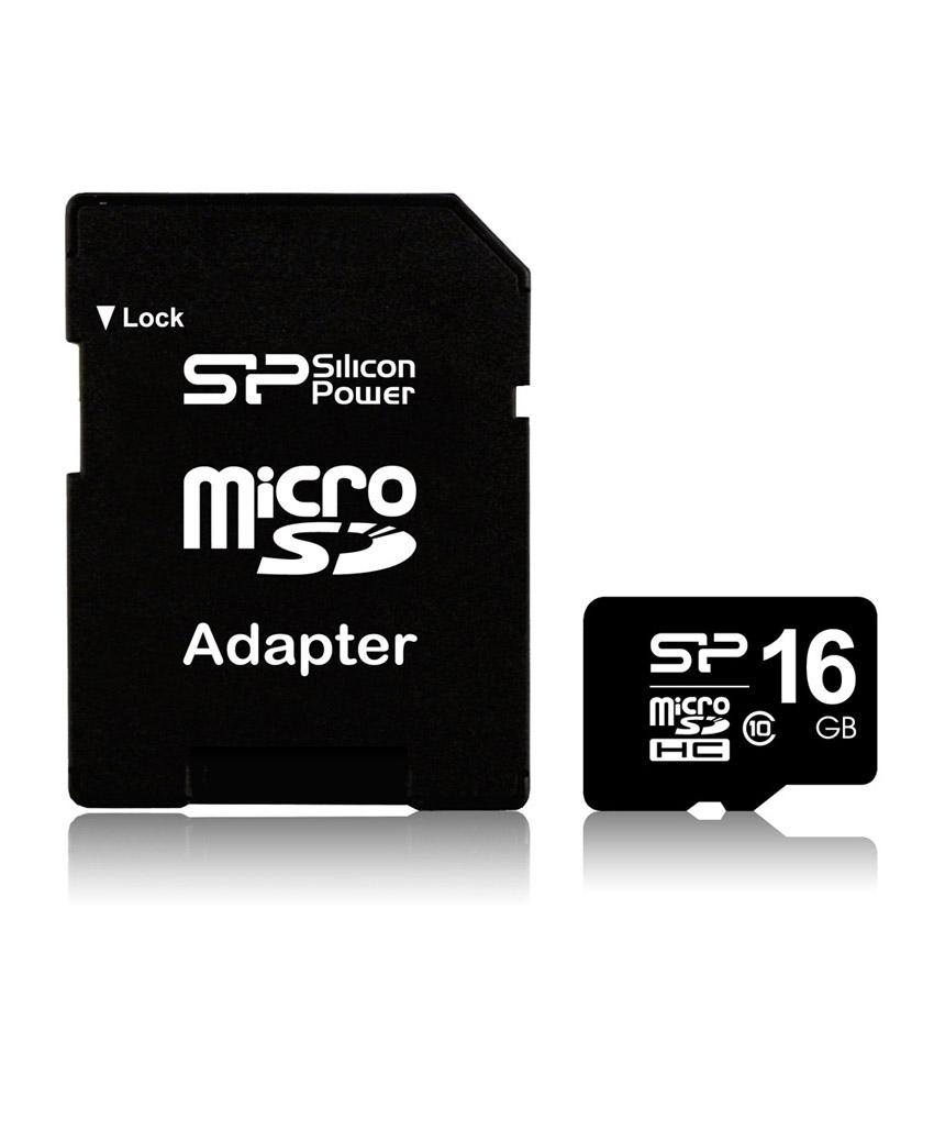
- 16Go SD card
The storage for the Raspberry Pi
Electronics:
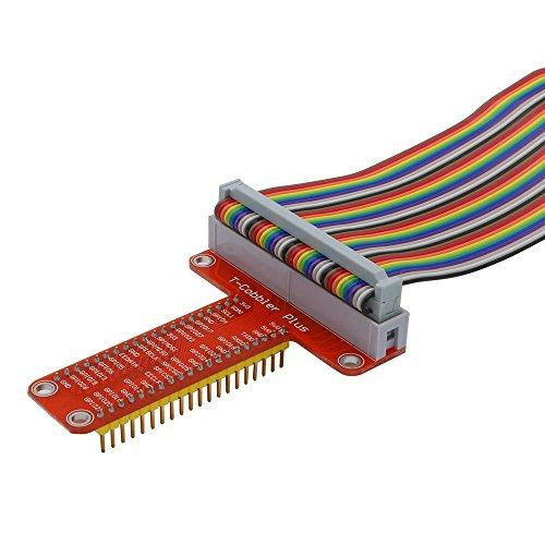
With this T-type breakout board , you can easily break out the GPIO pins of the
Raspberry Pi on a breadboard to quickly start prototyping.
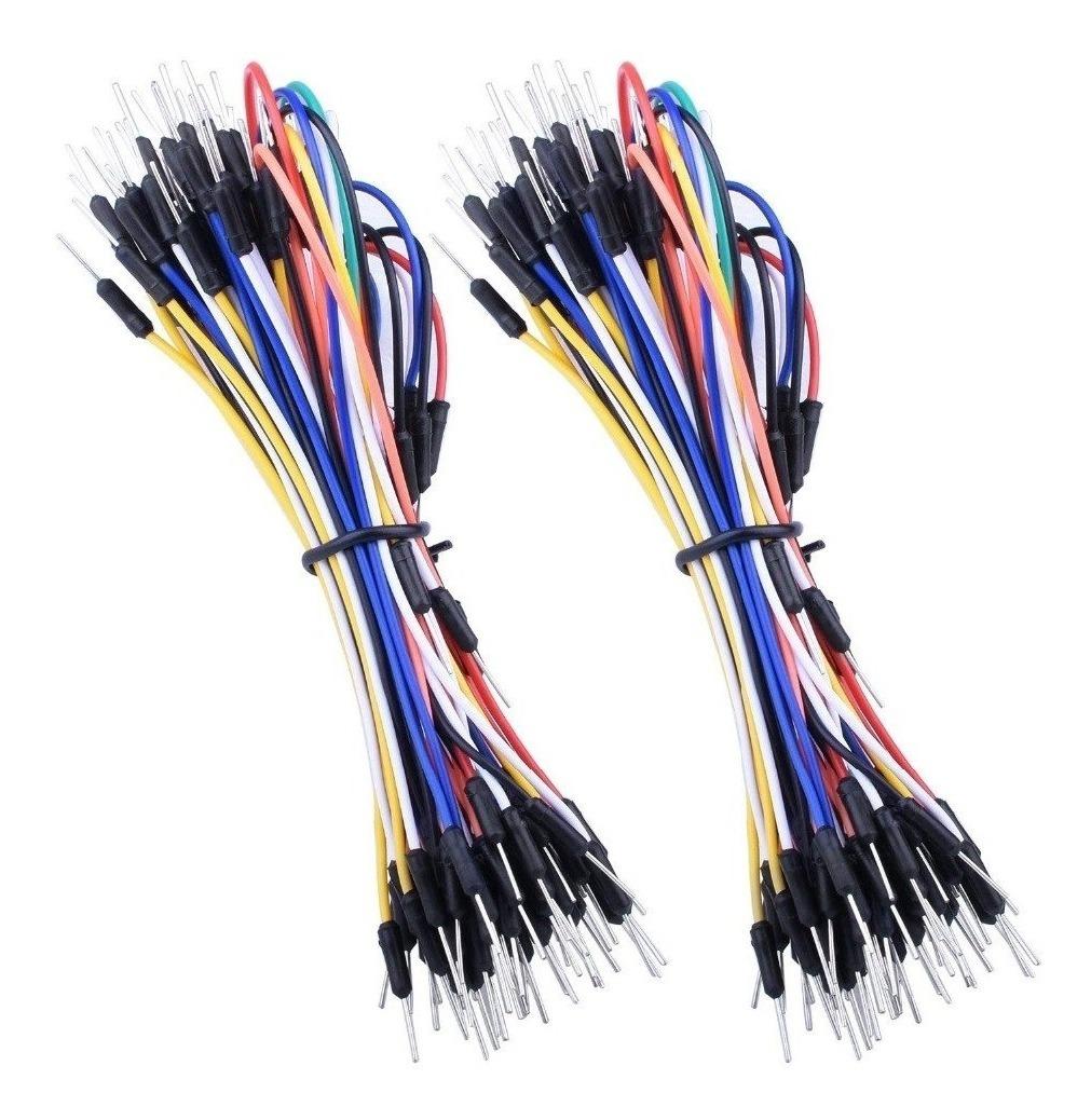
wiring the sensors and modules.
For the wiring of the sensors and the modules.
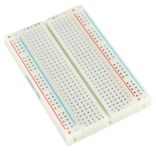
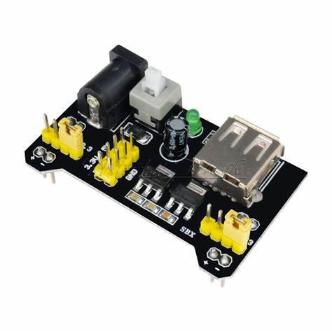
For making the wiring easier
Serves to hinder the passage of an electric current, to offer resistance to it, resulting
in a voltage drop across the resistor.
Sensors:
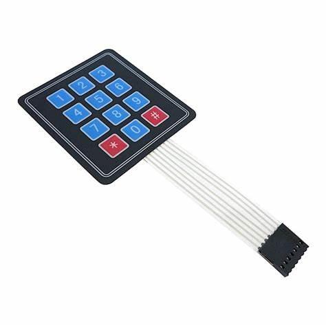
For user input on the hardware
To insert and remove products via their barcode on the hardware
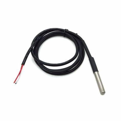
To measure the temperature
Actuators:
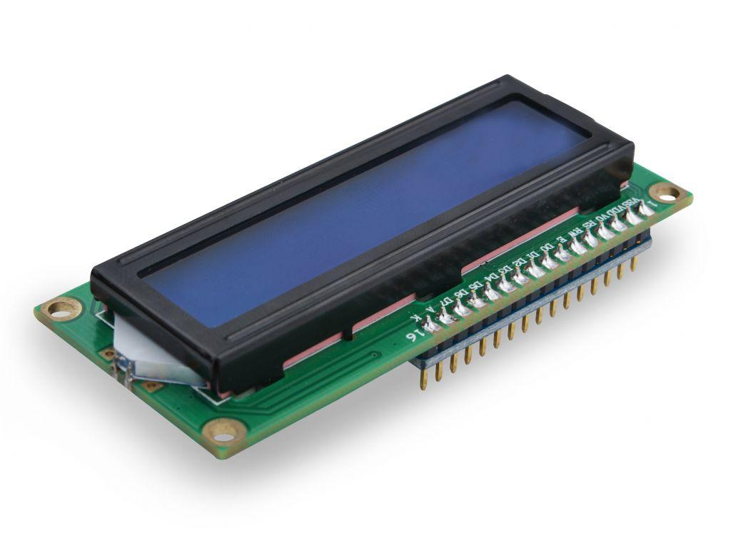
Displays the IP address of the web server and the various input menus
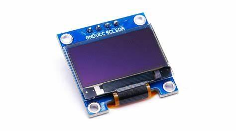
Displays temperature & number of products present & logo
Casing:
- An aluminium plate
- Metal screw + nut 3x30
- Blind rivets
Tools:
- Superglue
- Steel square
- ballpoint
- Tape measure
- A jigsaw with a blade for aluminium
- Line level gauge
- hammer
- 3mm metal screw + nut
- Blind rivets
- ...
Price:
~€193,26
Downloads
Prototyping
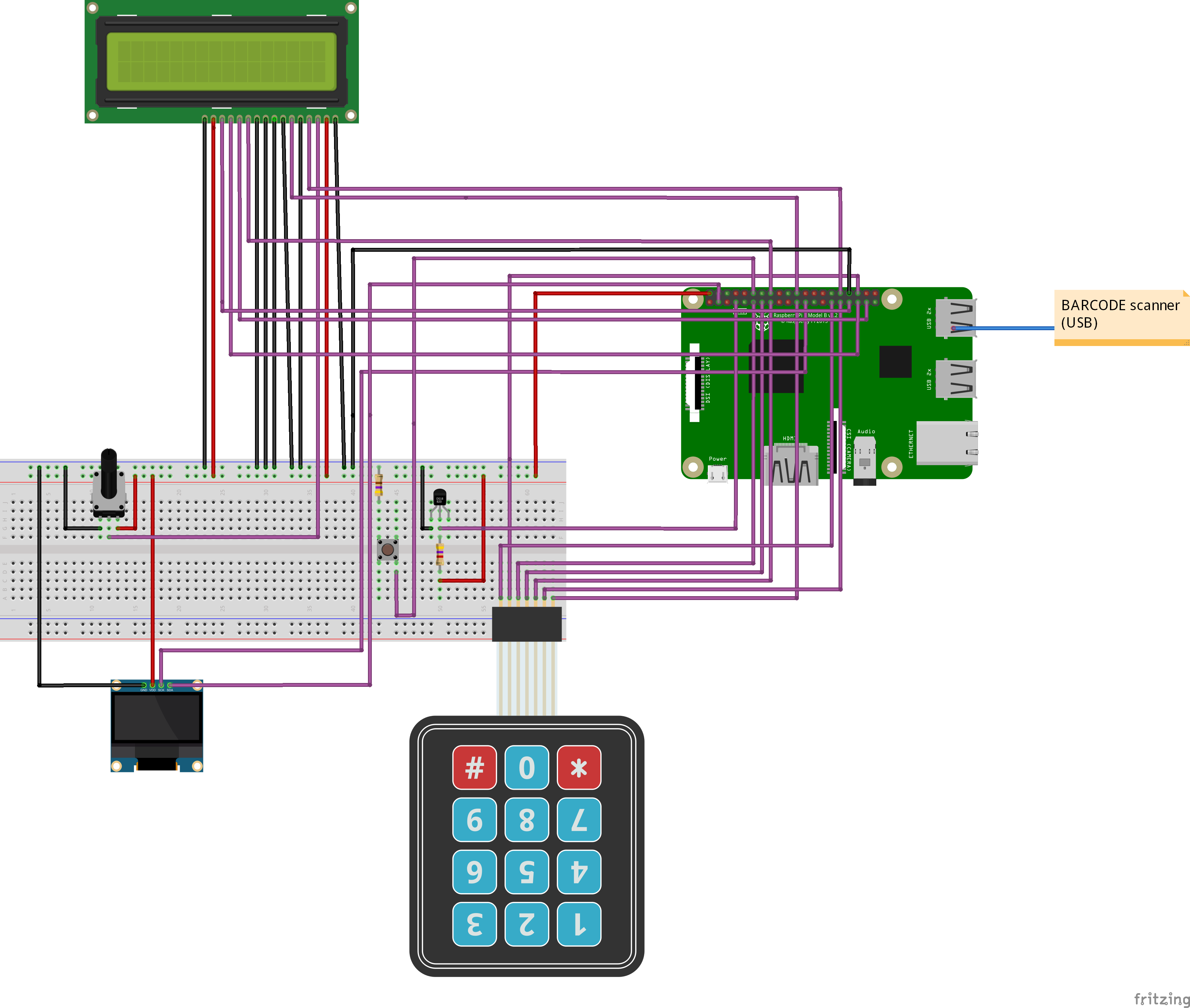
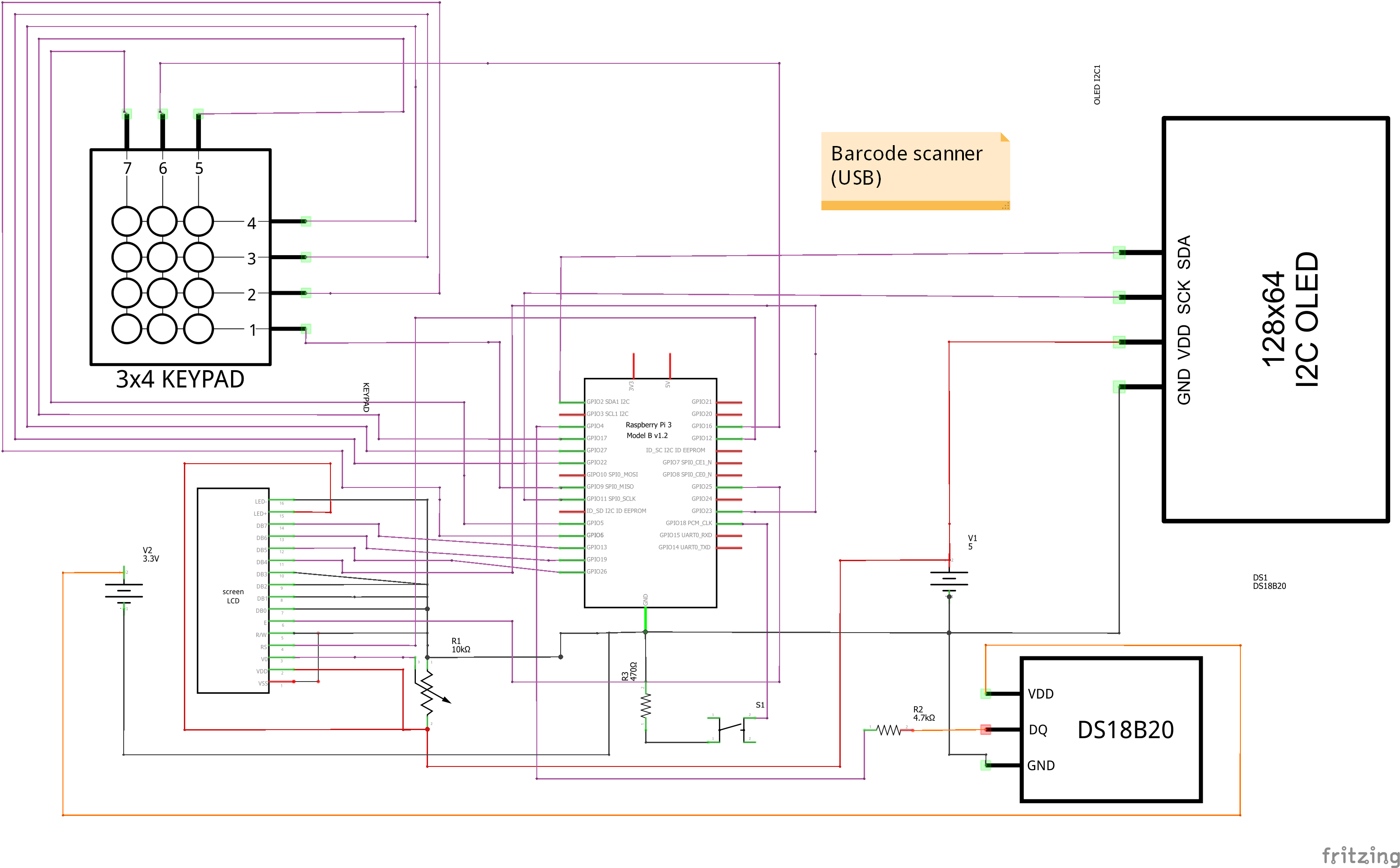
Make this circuit, make sure there are no shorts! You can see the circuit closer below if you wish.
Color code:
Red = 5V
Purple = Data cables
Orange = 3.3V
Black = Ground
pins LCD Display:
DB7: GPIO13
DB6: GPIO19
DB5: GPIO26
DB4: GPIO23
DB3: GND
DB2: GND
DB1: GND
DB0: GND
LED+: 5V
LED-:GND
E: GPIO20
RS : GPIO21
V0: analog pin potentiometer
R/W: GND
VSS: GND
VDD: 5V
Pins Temperature sensor:
DQ: GPIO4
GND: GND
VDD: 3.3V
Note if the line is orange it means it MUST be at 3.3V and not at 5V don't forget to put a resistor where needed, the temperature sensor needs a resistor of 4.7KOhm.
Pins OLED Display:
SDA: GPIO2(SDA1 I2C)
SCK: GPIO11(SPIO_SCK)
VDD : 5V
GND : GND
Barcode scanner:
USB port
3X4 Kepad:
R1:GPIO9
R2:GPIO6
R3:GPIO22
R4:GPIO27
C1: GPIO24
C2: GPIO12
C3: GPIO5
Shutdown button
GPIO18
Prepare the Raspberry Pi
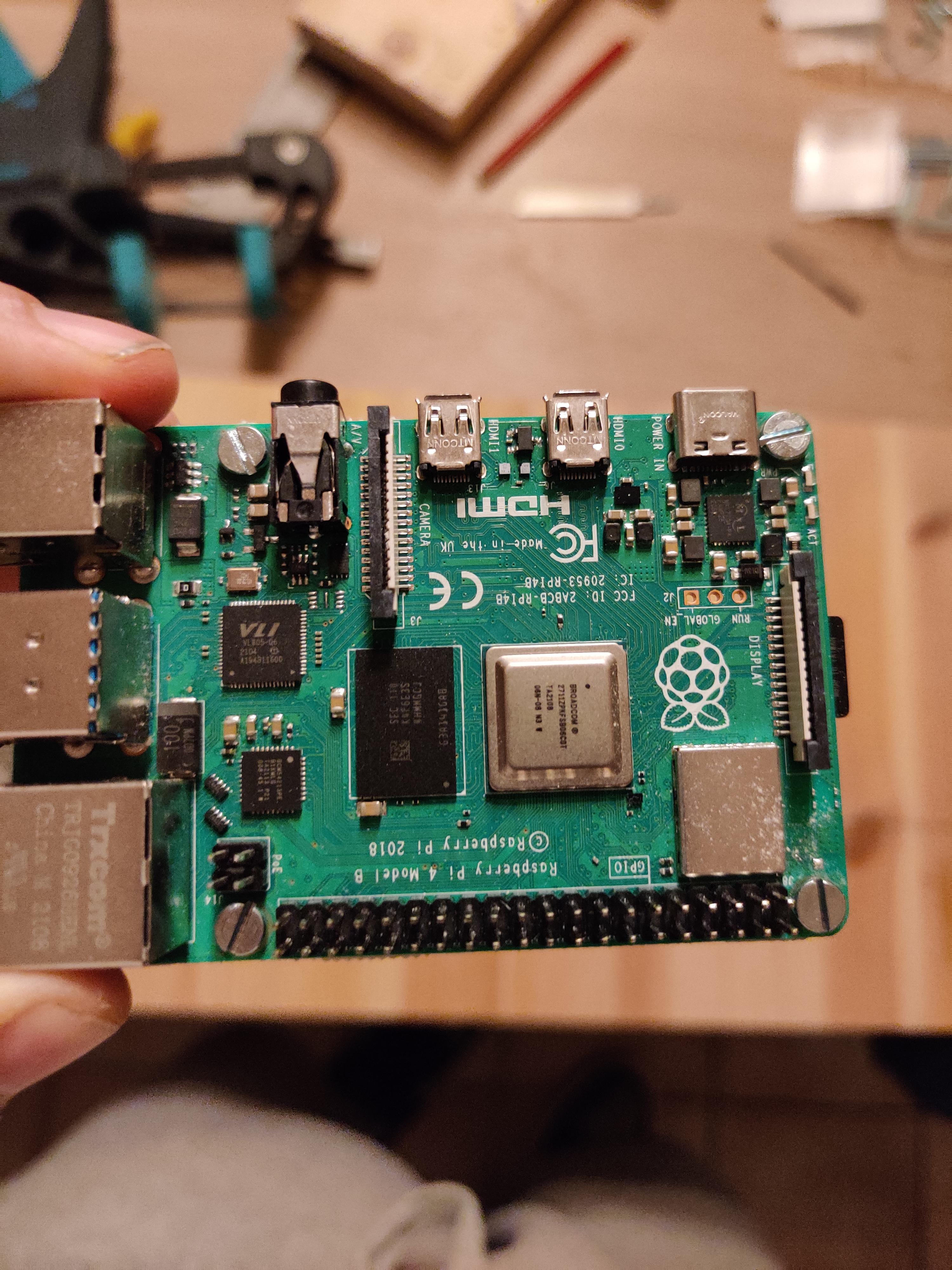
Dowload the image
- Download the Raspberry Pi os, the desktop version from here
- If you don't know how to install an image, here is a tutorial
Once the image is downloaded and installed in your raspberry pi
- Use an ssh client to login e.g. putty or vnc, the ip address to login is 169.254.10.1 and the port is 22 connection type is ssh
- On the first login the user is pi and the password is raspberry
- For the warning message click on yes
- It is always a good idea to create a user and change the password here is a tutorial
Once you are logged in
- Type sudo raspi-config in the terminal
- In the menu choose (6) Advanced > (1) Expand Filesystem
- Then reboot the raspberry pi with command :
sudo reboot now
After the reboot
- Go back to:
sudo raspi-config
- This time we go to (3) Interfaces
- Enable the one wire bus (i7)
- Enable the I2C(i5) bus
- Enable the SPI(i4) bus
- Enable the vnc(i3) it will make it easier if there are issues in the terminal
- Reboot the raspberry pi with command:
sudo reboot now
Connect the raspberry pi to the wifi
- To get administrator rights
sudo -i
- Once your administrator type:
wpa_passphrase <your_SSID@Home> <your_wifi password> >>/etc/wpa_supplicant/wpa_supplicant.conf
- Replace <your_SSID@Home> with the name of your home network and <your_wifi password> with the corresponding password.
- Type now:
wpa_cli -i wlan0 reconfigure
- To reload your wireless network card in the RasPi.
A test to see if you are connected to the internet:
ping www.google.com
- If you see this you're connected to the wifi:
PING www.google.com(ams15s41-in-x04.1e100.net (2a00:1450:400e:802::2004)) 56 data bytes
64 bytes from ams16s21-in-x04.1e100.net (2a00:1450:400e:802::2004): icmp_seq=1 ttl=113 time=23.2 ms
64 bytes from ams16s21-in-x04.1e100.net (2a00:1450:400e:802::2004): icmp_seq=2 ttl=113 time=22.2 ms
64 bytes from ams16s21-in-x04.1e100.net (2a00:1450:400e:802::2004): icmp_seq=3 ttl=113 time=23.5 ms
^C
--- www.google.com ping statistics ---
3 packets transmitted, 3 received, 0% packet loss, time 2003ms
Update the Raspberry Pi
- sudo apt update to check which updates are available.
- sudo apt upgrade -y to install the available updates.
Install Apache server
sudo apt install apache2 -y
Install mariaDB
sudo apt install mariadb-server mariadb-client -y
Securing MariaDB
mysql_secure_installation
- First you will be asked to enter the current root password for MariaDB. As there is none yet, just press Enter here.
- Next, you can change the password. Choose a password you can remember for sure!
- The next step is to delete anonymous users. Choose y here
- Prohibit root from logging in remotely. Choose y here.
- Then remove test database and access? Choose y.
- Finally, reload privilege databases: y
Create MariaDB User
- Next, we configure the user 'choose a name' with a password on the MariaDB server.
- mysql -u root -p to access the MariaDB server
grant all on *.* to 'yourname'@'localhost' identified by 'yourpassword';
grant grant option on *.* to 'yourname'@'localhost';
flush privileges;
exit;
- Creates a new user with password who gets rights to all databases.
- flush privileges Reload privileges
- exit Exit from the MariaDB server
Install the library's and python3
sudo pip install flask-cors
sudo pip install flask-socketio
sudo pip install simple-websocket
sudo pip install mysql-connector-python
sudo pip install gevent
sudo pip install gevent-websocket
sudo pip install selenium
sudo apt install chromium-chromedriver
sudo apt install python3-dev python3-pip
After installation reboot the raspberry
sudo reboot
Install the code
git clone https://github.com/howest-mct/2021-2022-projectone-DewilLucas.git
Import the Database
Start mysqlworkbench on your laptop
- Make a new connection.
- Connection Method:Standard TCP/IP over SSH.
- SSH Hostname: 169.254.10.1
- SSH Username: pi(or the username you gave it)
- SSH Password: raspberry(or the password you gave it)
- MySQL Hostname: 127.0.0.1
- MySQL Server Port: 3306
- Username: yourname (the name you gave in the database)
- Password: yourpassword(the password you gave in the database)
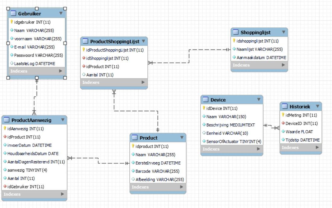
The Database
The database has 7 tables:
- Gebruiker (User): Contains the necessary information about the users
- UserID
- Name
- First name
- E-mail (for the bot so that it can send e-mails)
- Password
- Last login
- ProductAanwezig (ProductPresent): keep all products in the refrigerator
- idPresent
- idProduct
- entryDate
- expiryDate
- Number of Days Resting
- available
- number
- idUser
- Product: table that keeps track of the products with their barcode
- idproduct
- name
- first insertion
- barcode
- image
- ProductShoppingLijst(ProductShoppingList): shopping list not yet available, this will come in a future update keep an eye on it!
- idproductShoppingList
- idshoppinglist
- idproduct
- number
- ShoppingLijst(Shopping list): shopping list not yet available, this will come in a future update keep an eye on it!
- idshoppinglist
- nameList
- CreationDate
- Device(these are the sensors/actuators):
- idDevice
- Name
- description
- unit
- SensorOrActuator
- Historiek (history): Keep track of all measured values
- idMeasurement
- DeviceID
- value
- time
You can find the dump file on my Github Repository
Run It for the First Time
Test run
sudo /bin/python3 /backend/app.py
Start it up automatically
nano /etc/systemd/system/smartfridge.service
then type in it:
[Unit]
Description=smartFridge
After=network.target
[Service]
ExecStart=/usr/bin/python3 -u /home/student/2021-2022-projectone-DewilLucas/backend/app.py
WorkingDirectory=/home/student/2021-2022-projectone-DewilLucas/backend
StandardOutput=inherit
StandardError=inherit
Restart=always
User=student
[Install]
WantedBy=multi-user.target
!!!Save the file!!!
CTRL X --> y ENTER
Copy the service
Copy this file as root user to /etc/systemd/system with the command:
sudo smartfridge.service /etc/systemd/system/smartfridge.service
Test
You can test it by type in;
systemctl start smartfridge.service
You can also stop it:
systemctl stop smartfridge.service
The automatic start
sudo systemctl enable smartfridge.service
Code: Backend


Backend
The backend code was written in Python.
I used socketio to send the data live from the backend to the frontend.
To run multiple tasks at the same time, I used the threading library.
The data is fetched using a mysql server and so we use the connector of this in Python.
I also created a bot that sends out mails every day around midnight, using the emailPy library that I created.
In emailPy you can create your own account, I have put a link in there. That account is a random spam account so I don't really care if it is used.
Code: Frontend


.jpg)

Frontend
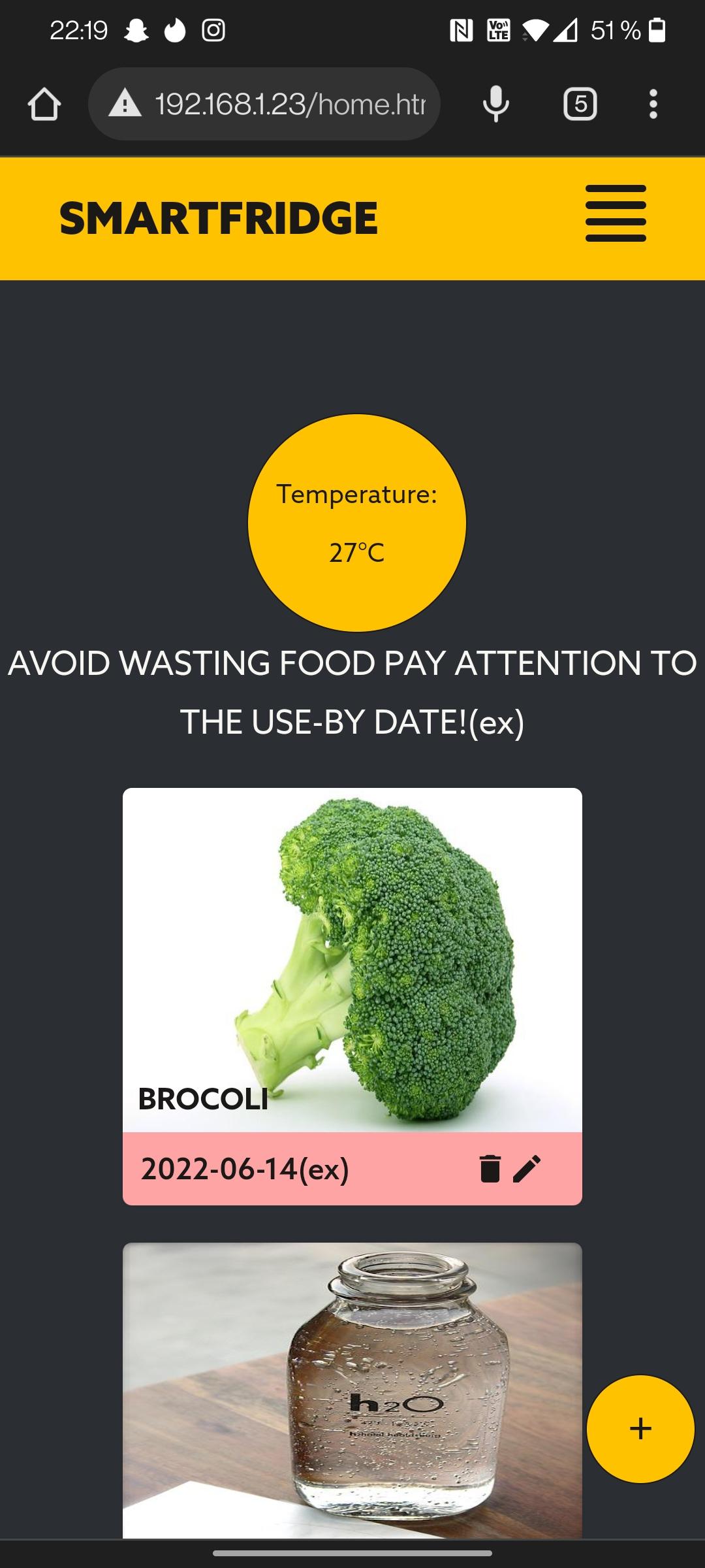
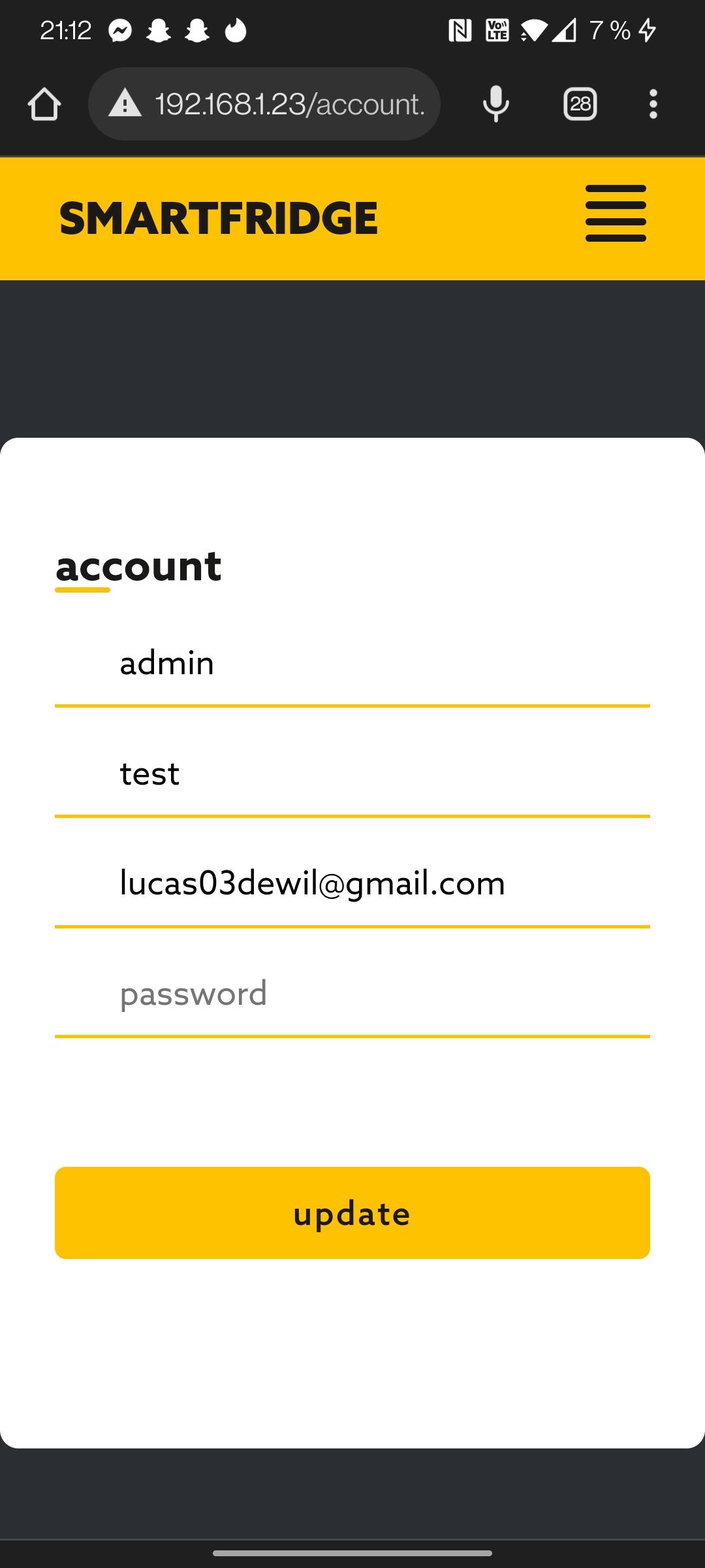
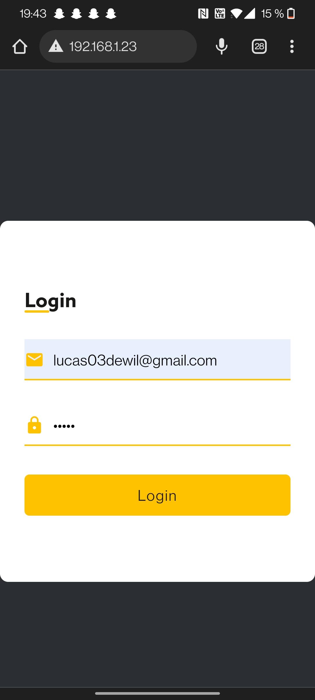
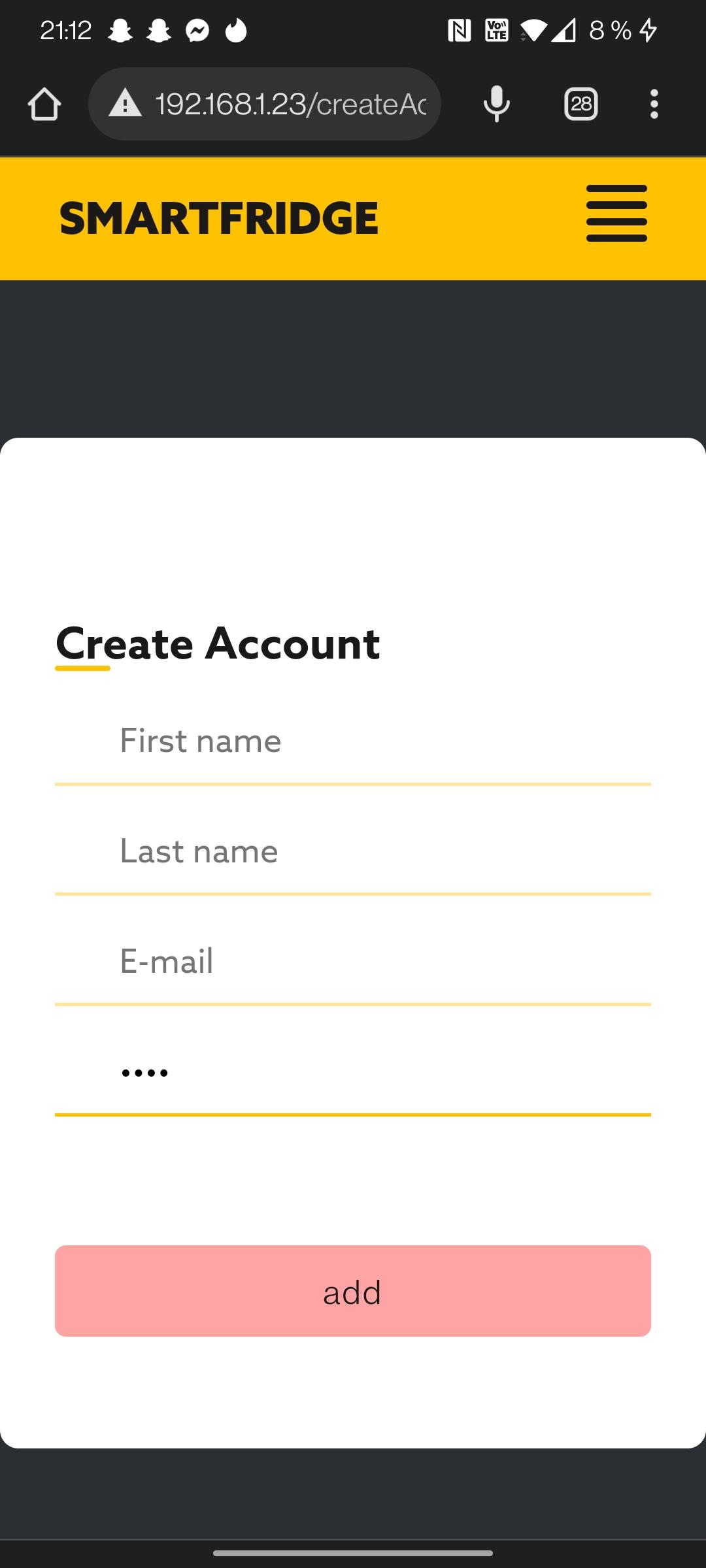
The frontend was written in HTML 5, the styling in CSS 3 and the script in javascript.
In javascript I have also used socketio so that the communication from the frontend can also go to the backend.
For the graph I used Apex Charts.
Design
.jpg)
.jpg)
.jpg)
.jpg)
.jpg)
.jpg)
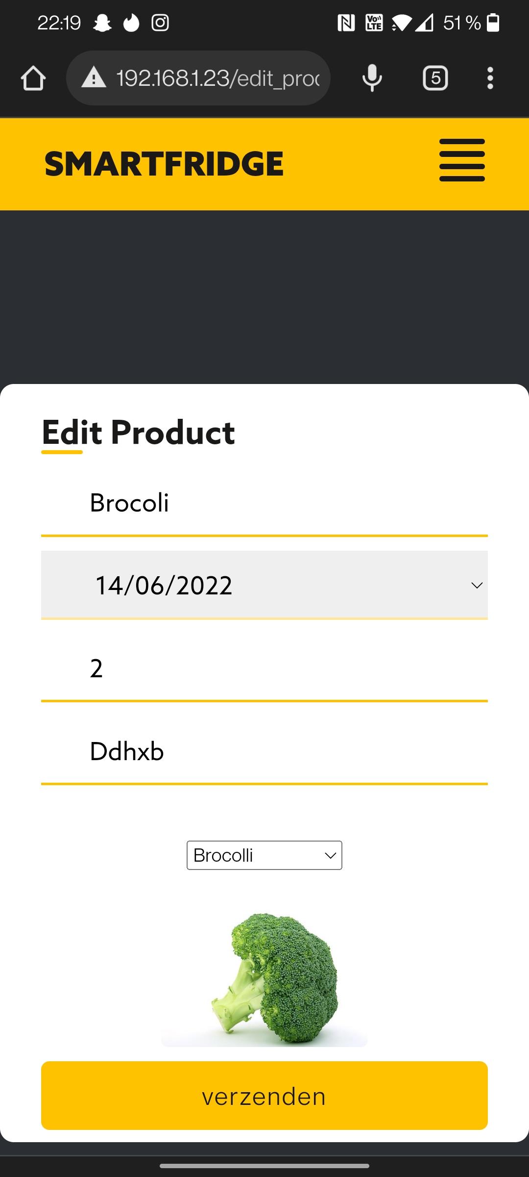
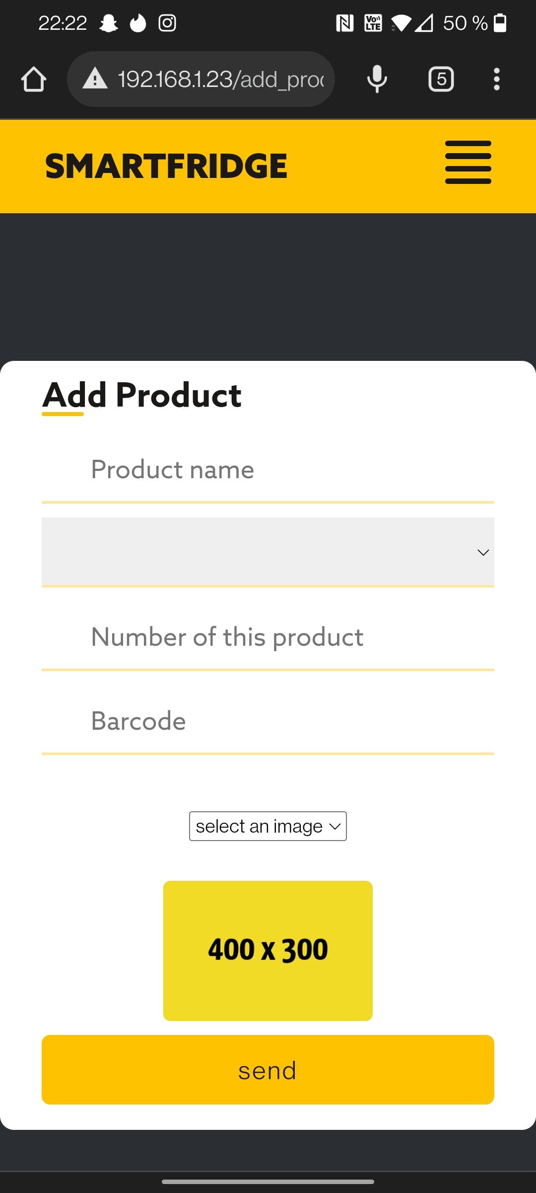
For the design, I wanted something that was user-friendly, not too many bells and whistles but the essence. I want to see the products that I should eat today or smell first and see if they are edible (forgot something in the fridge ? ;))
Building the Casing
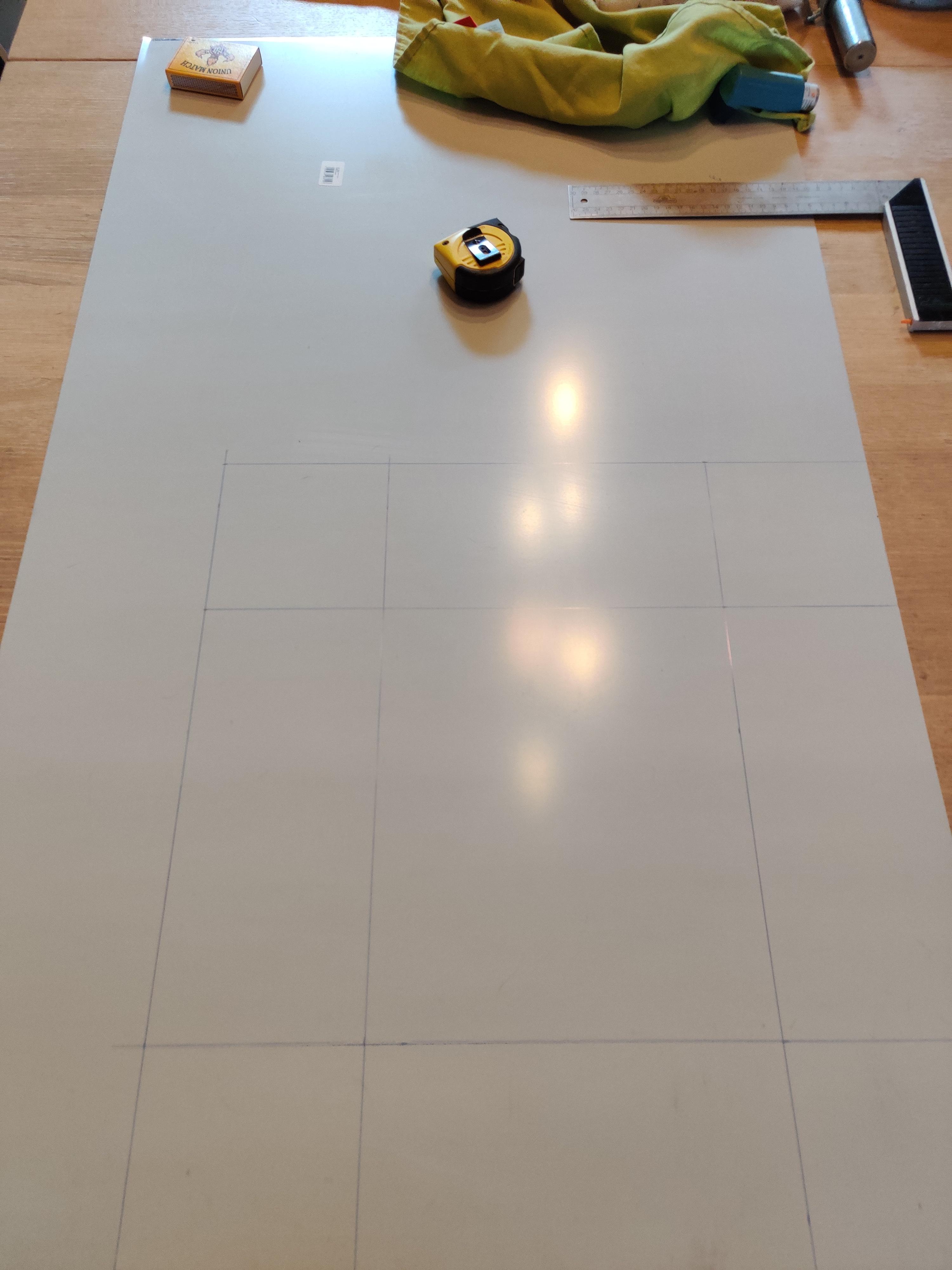
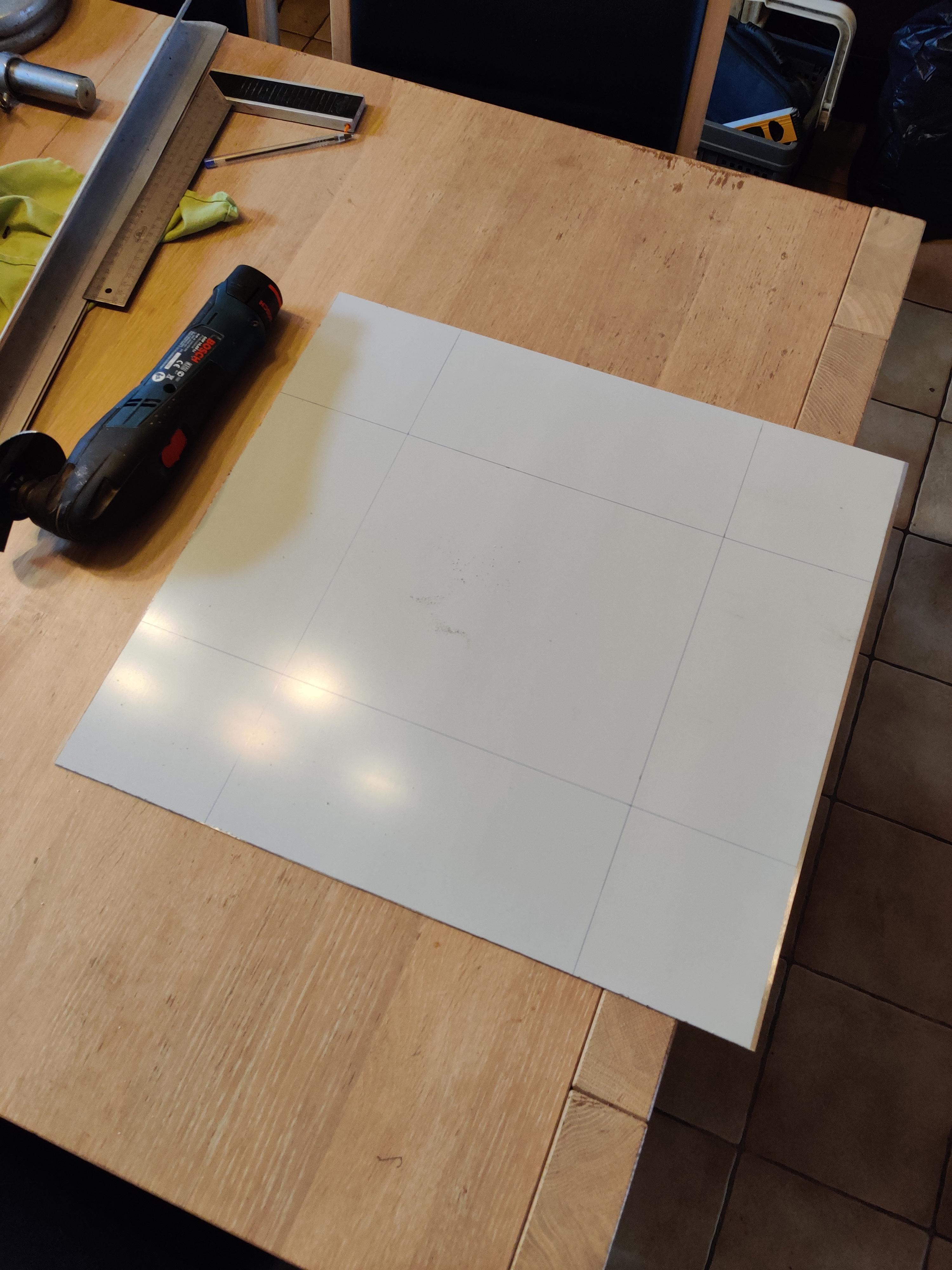
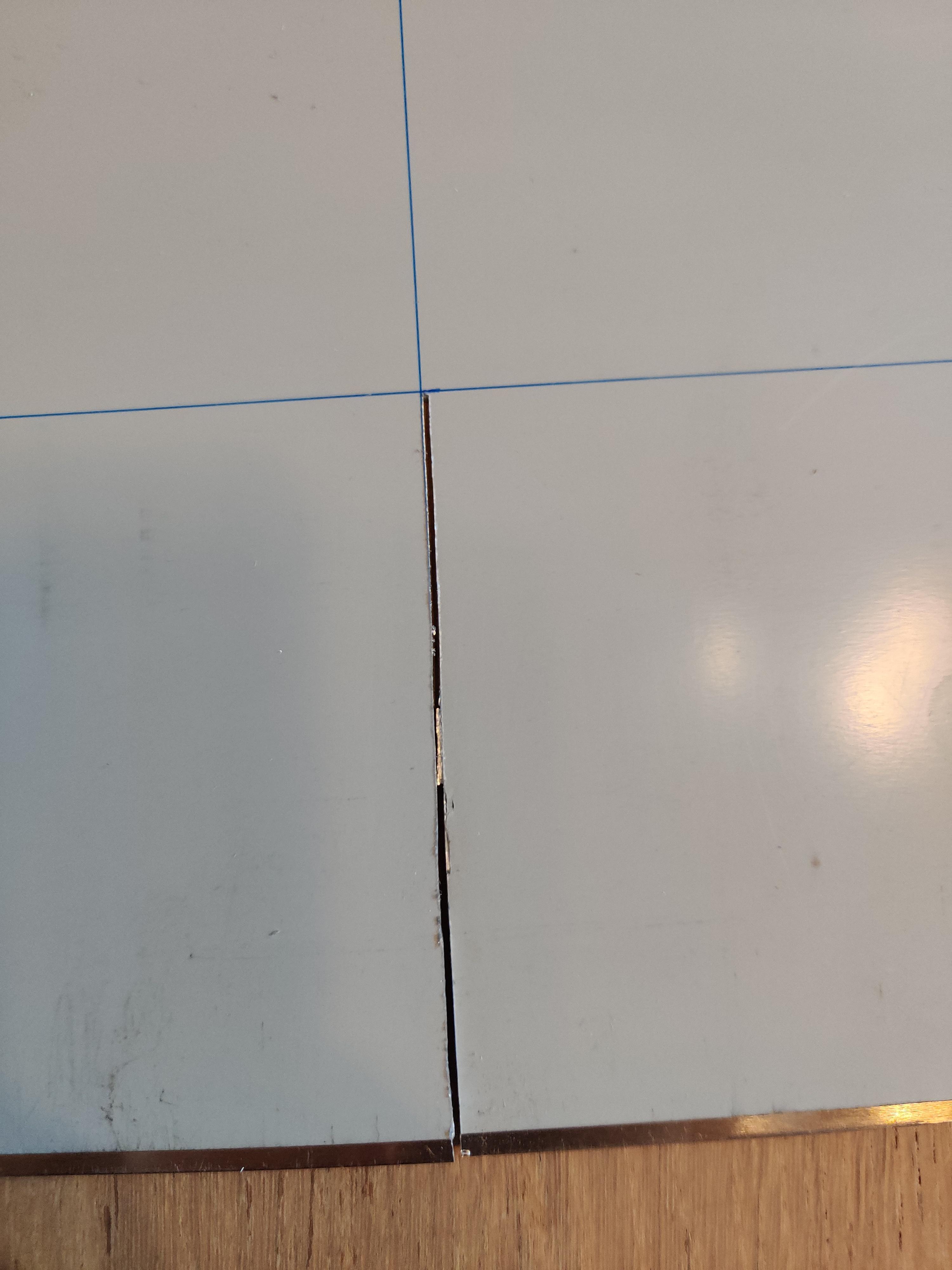
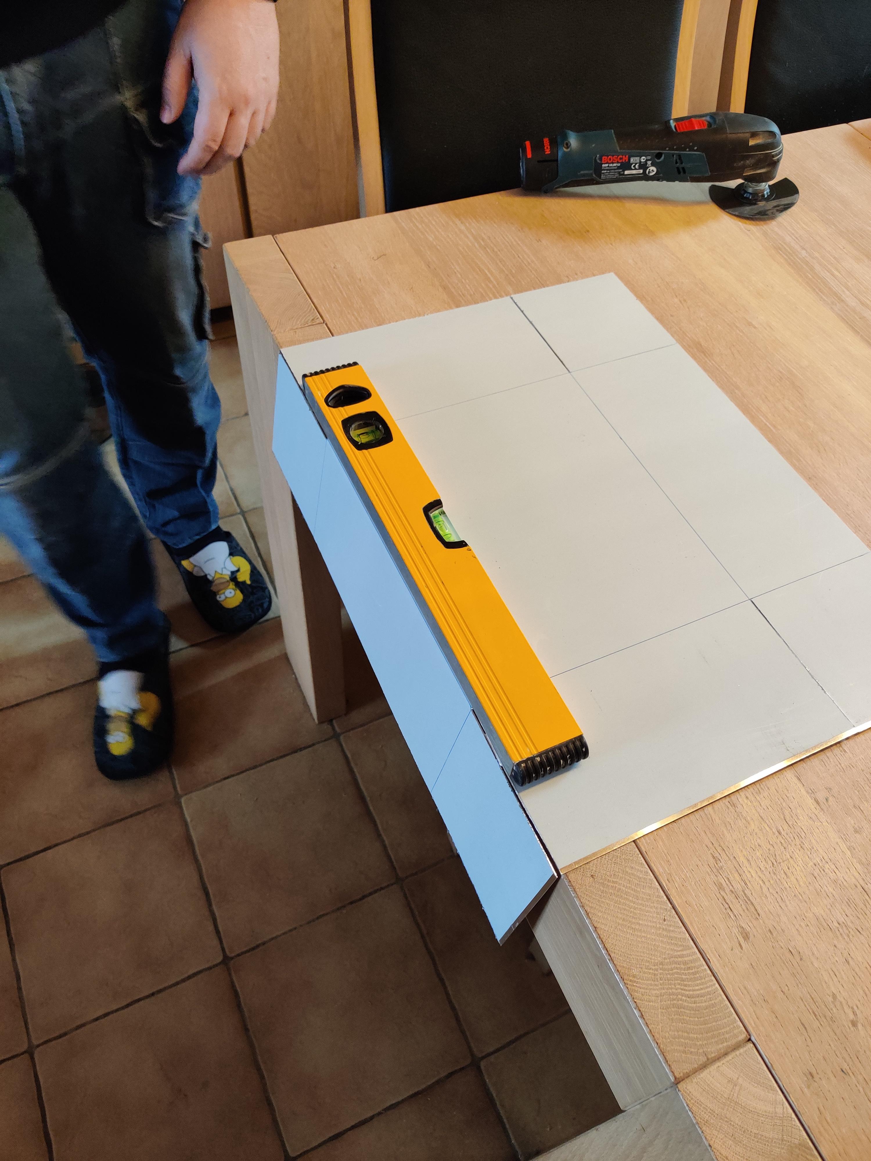
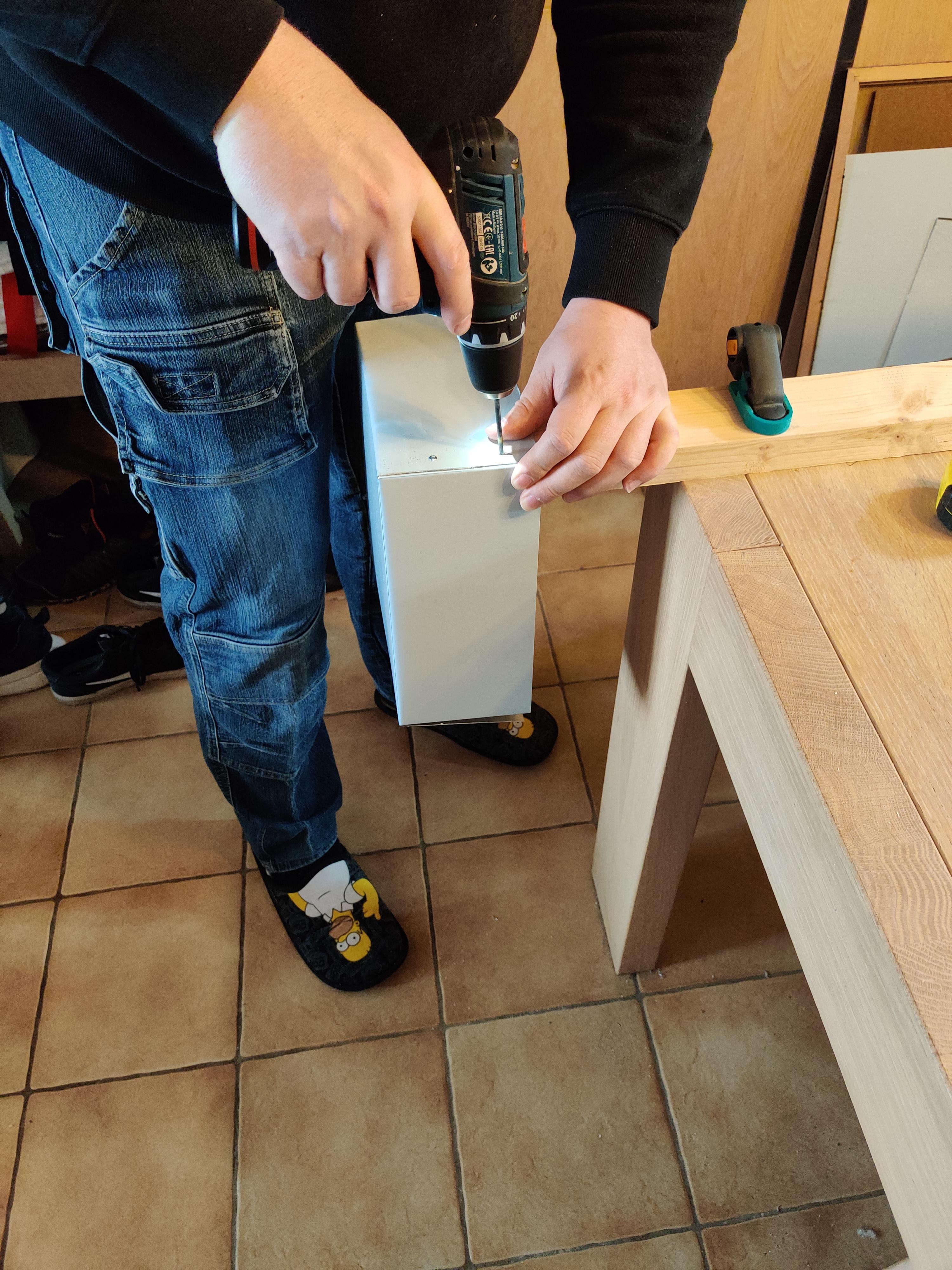
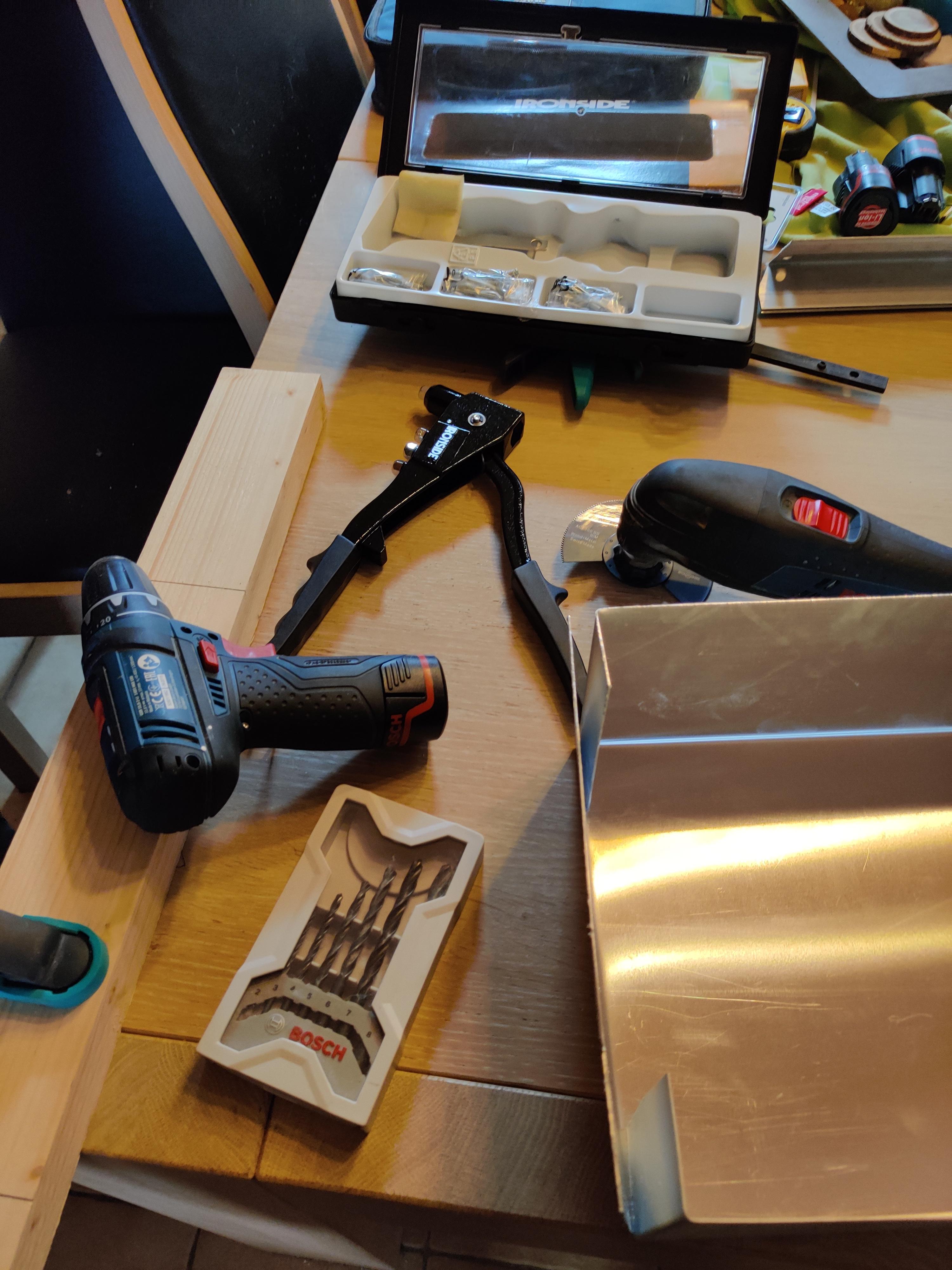
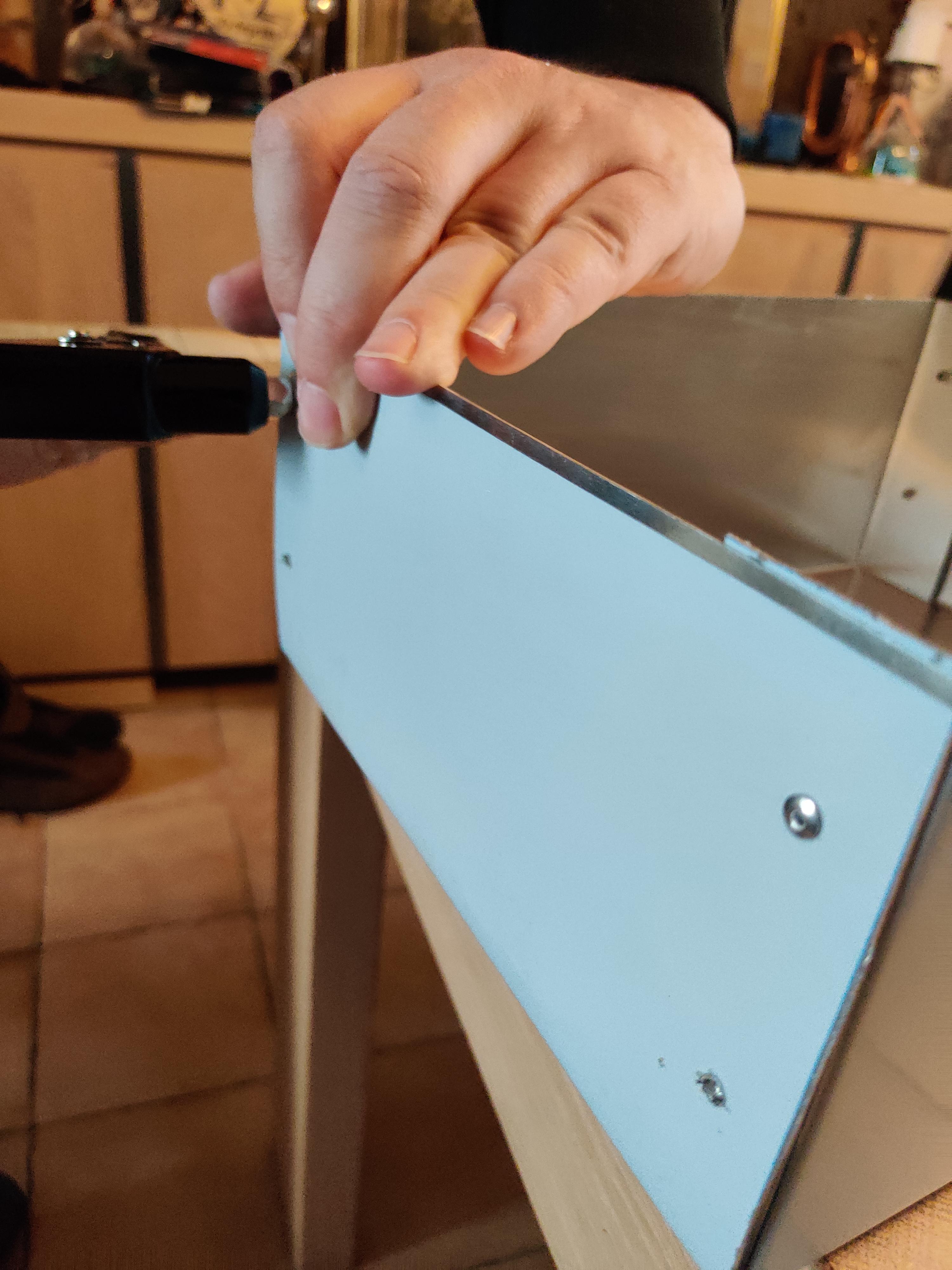
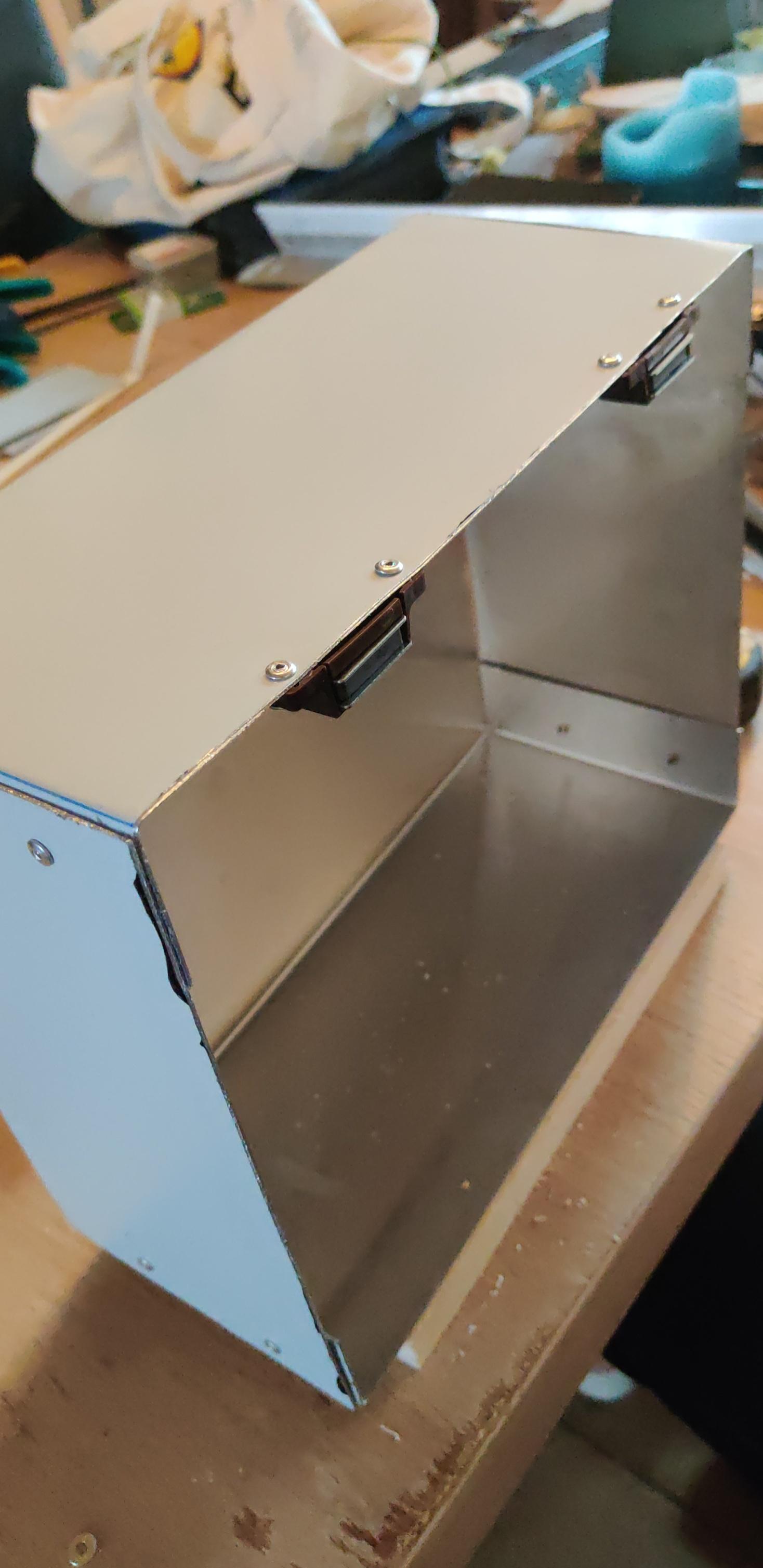
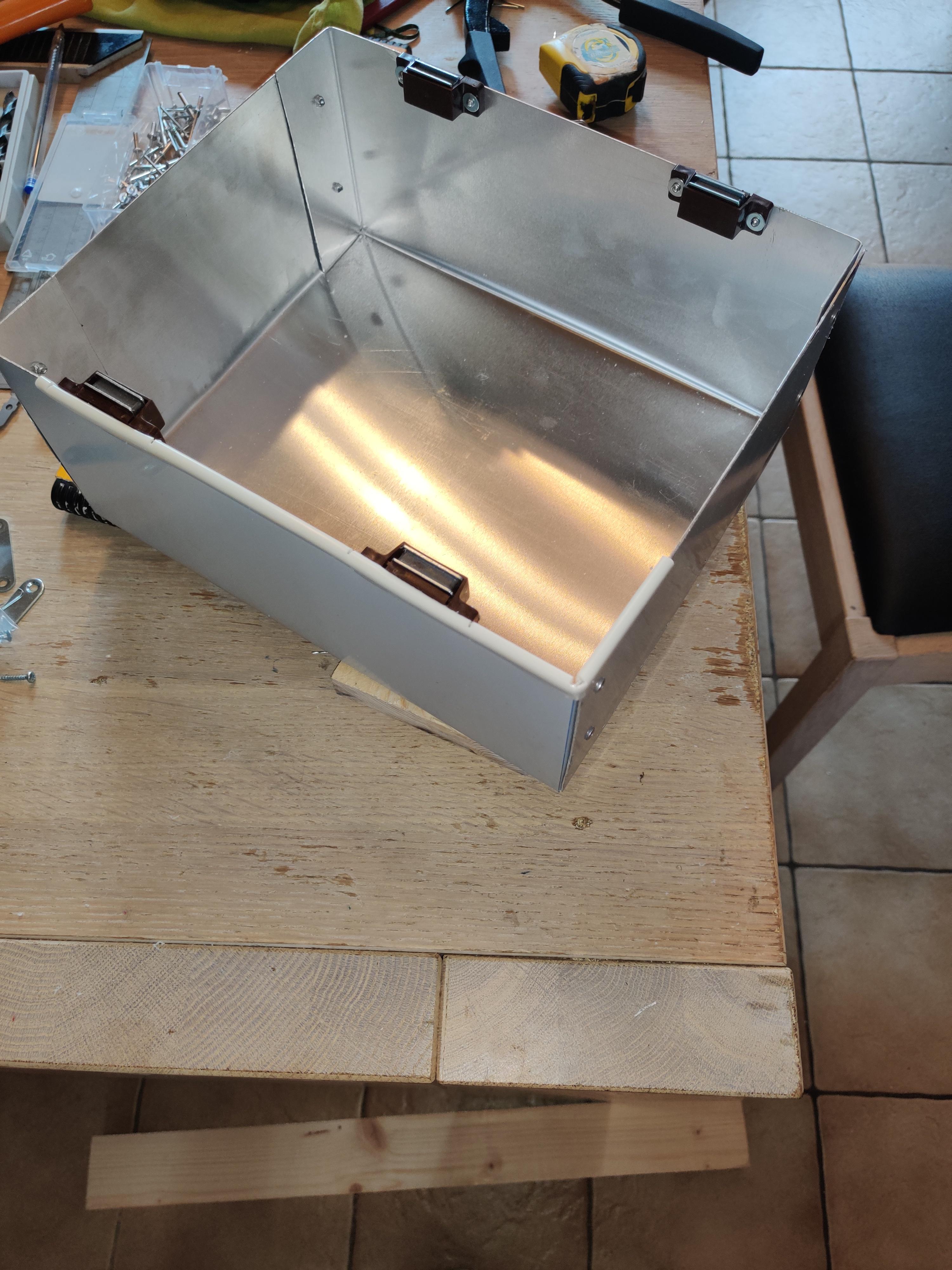
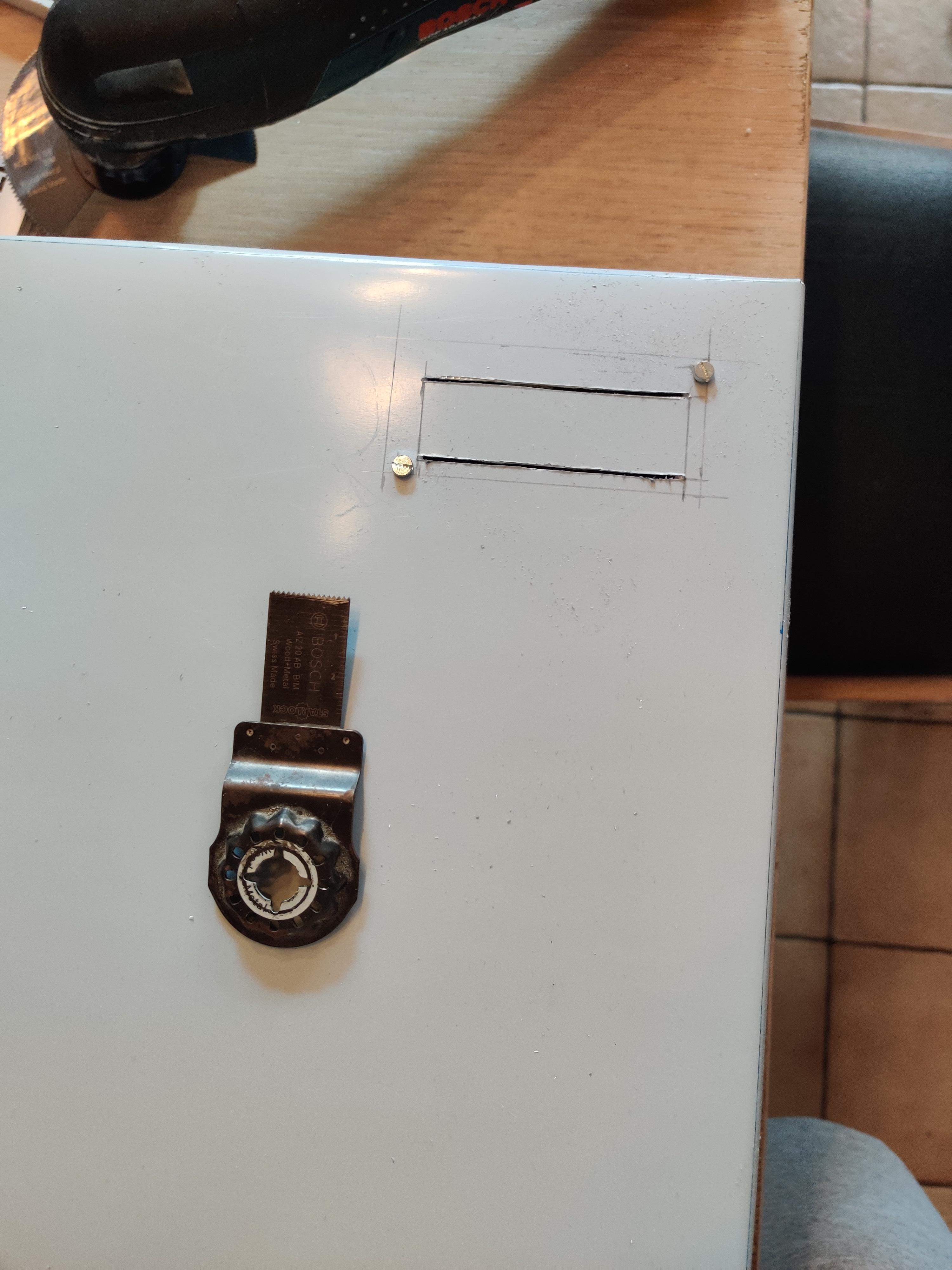
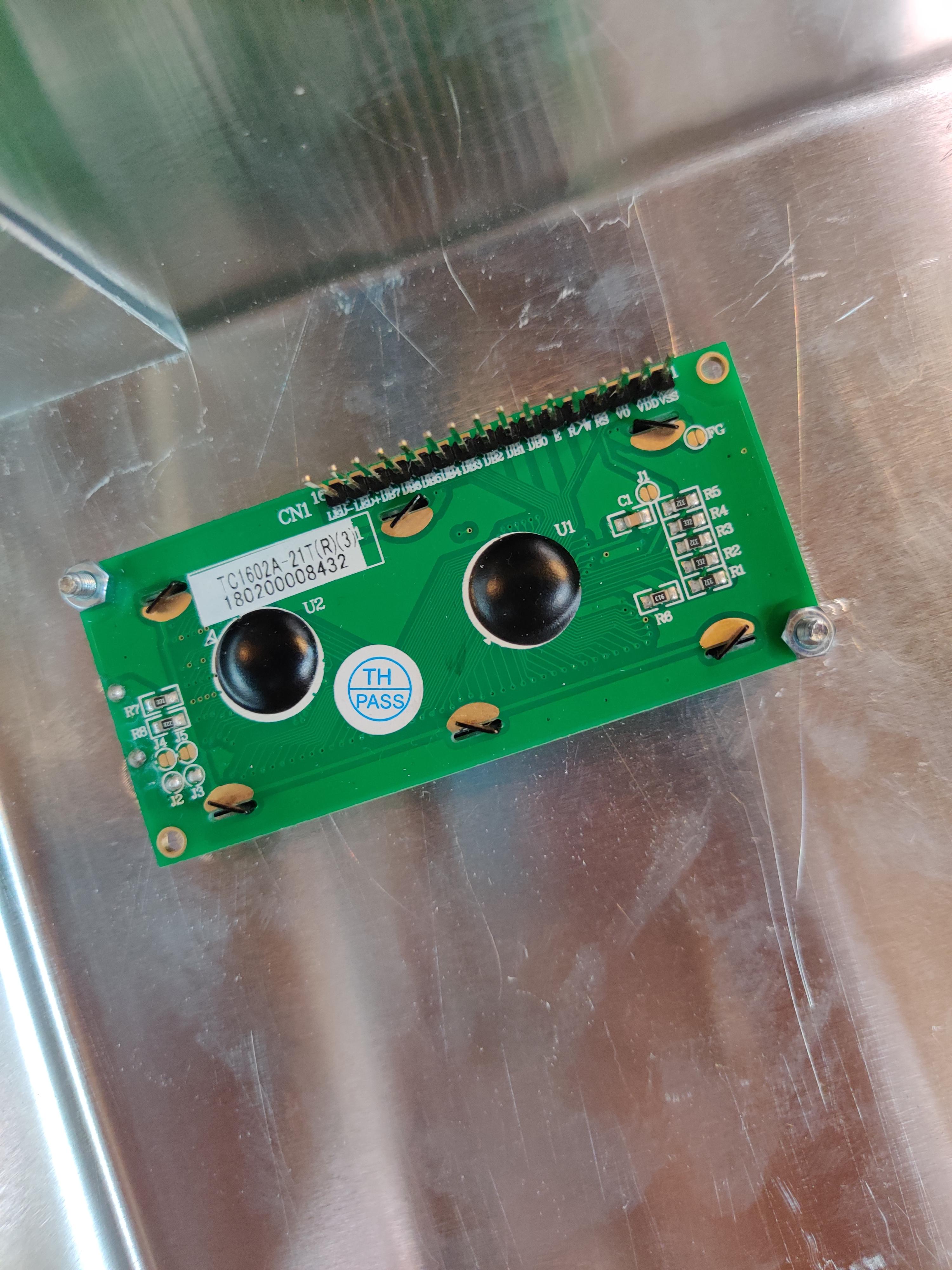
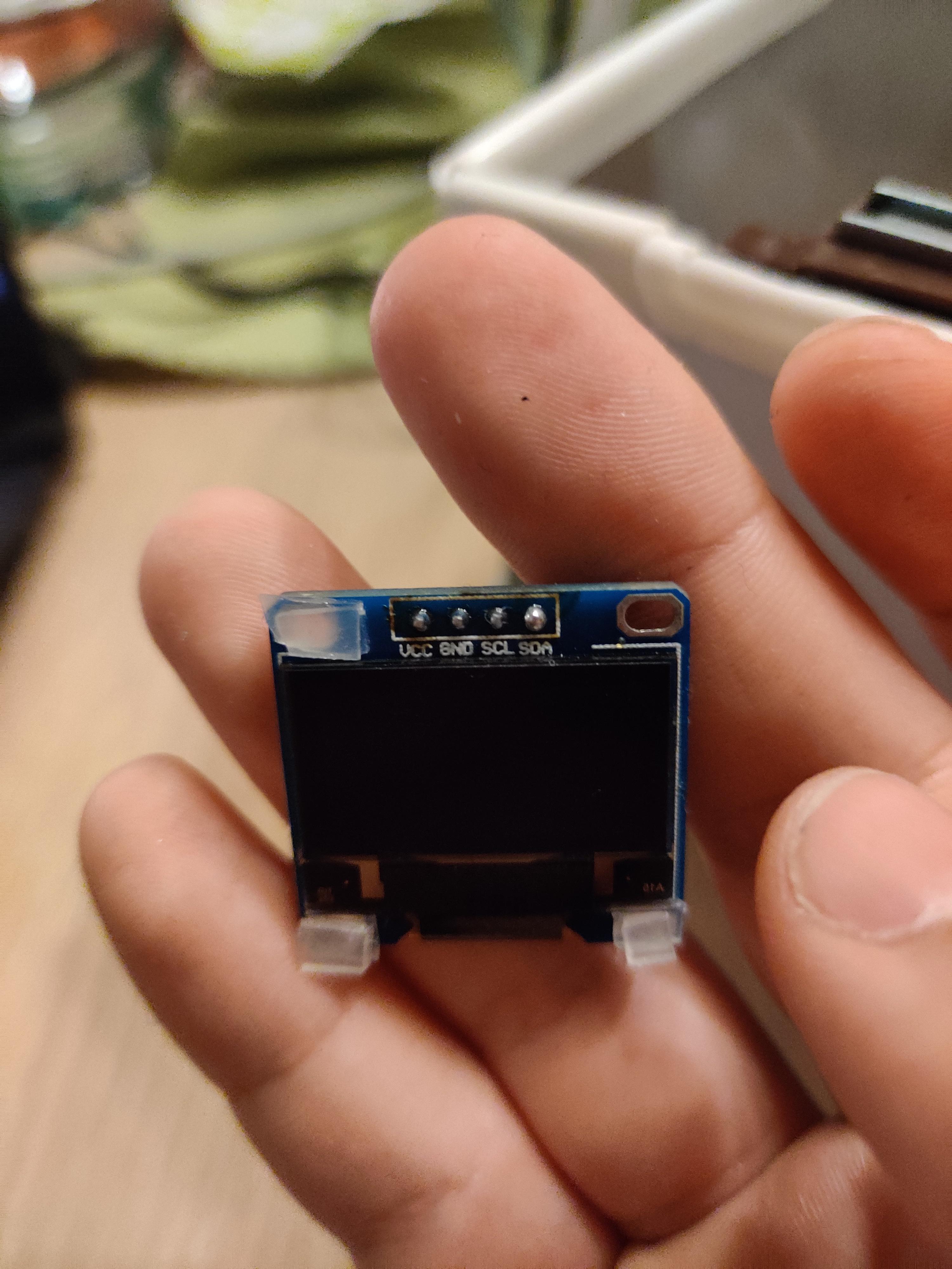
Material
For the housing I decided to work with aluminum, you can also work with other materials, but I thought this one was nicer and more suitable for a fridge. The advantage of aluminum is that it is a conductor that easily distributes the heat of my components.
Step 1)
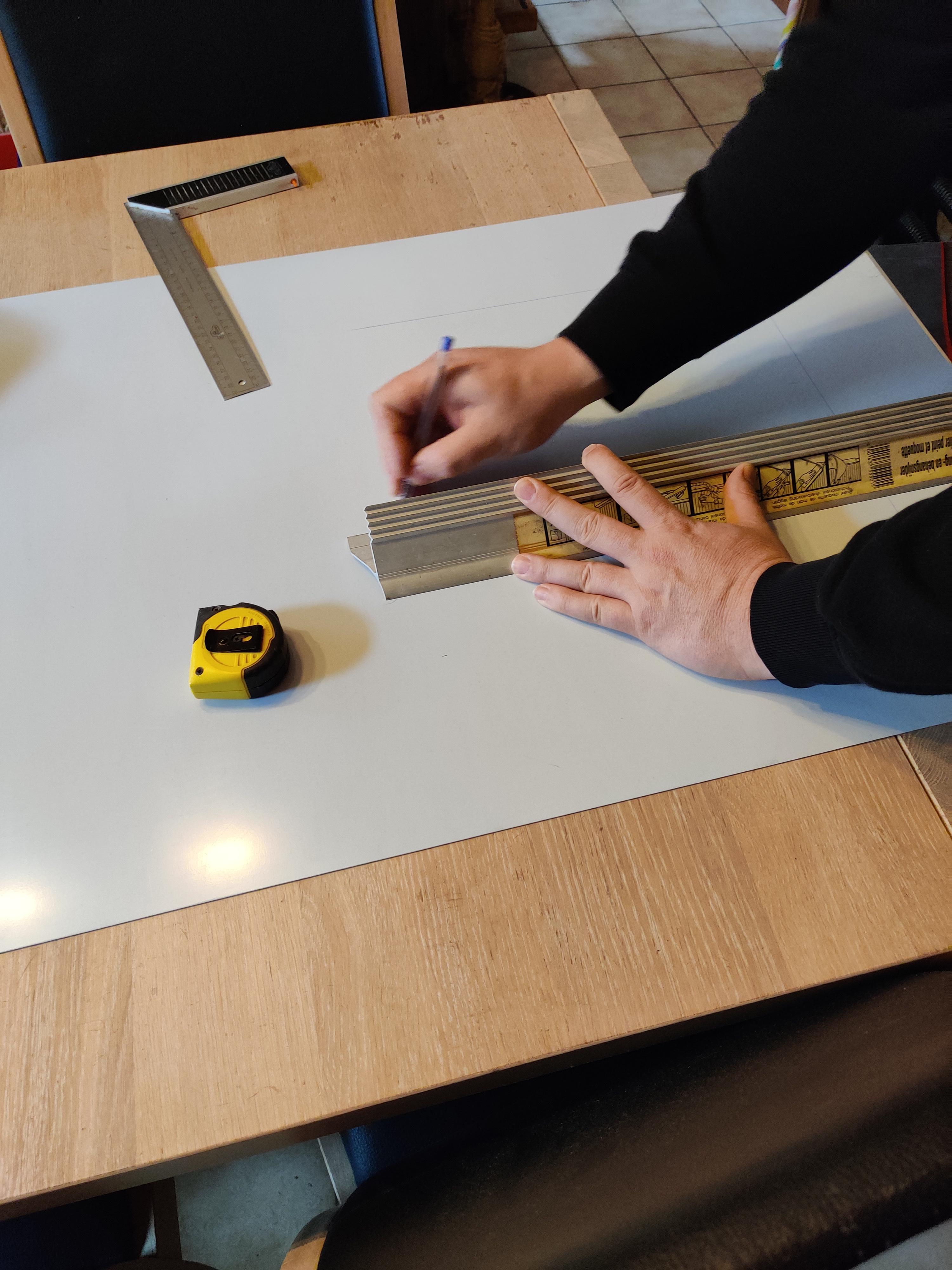
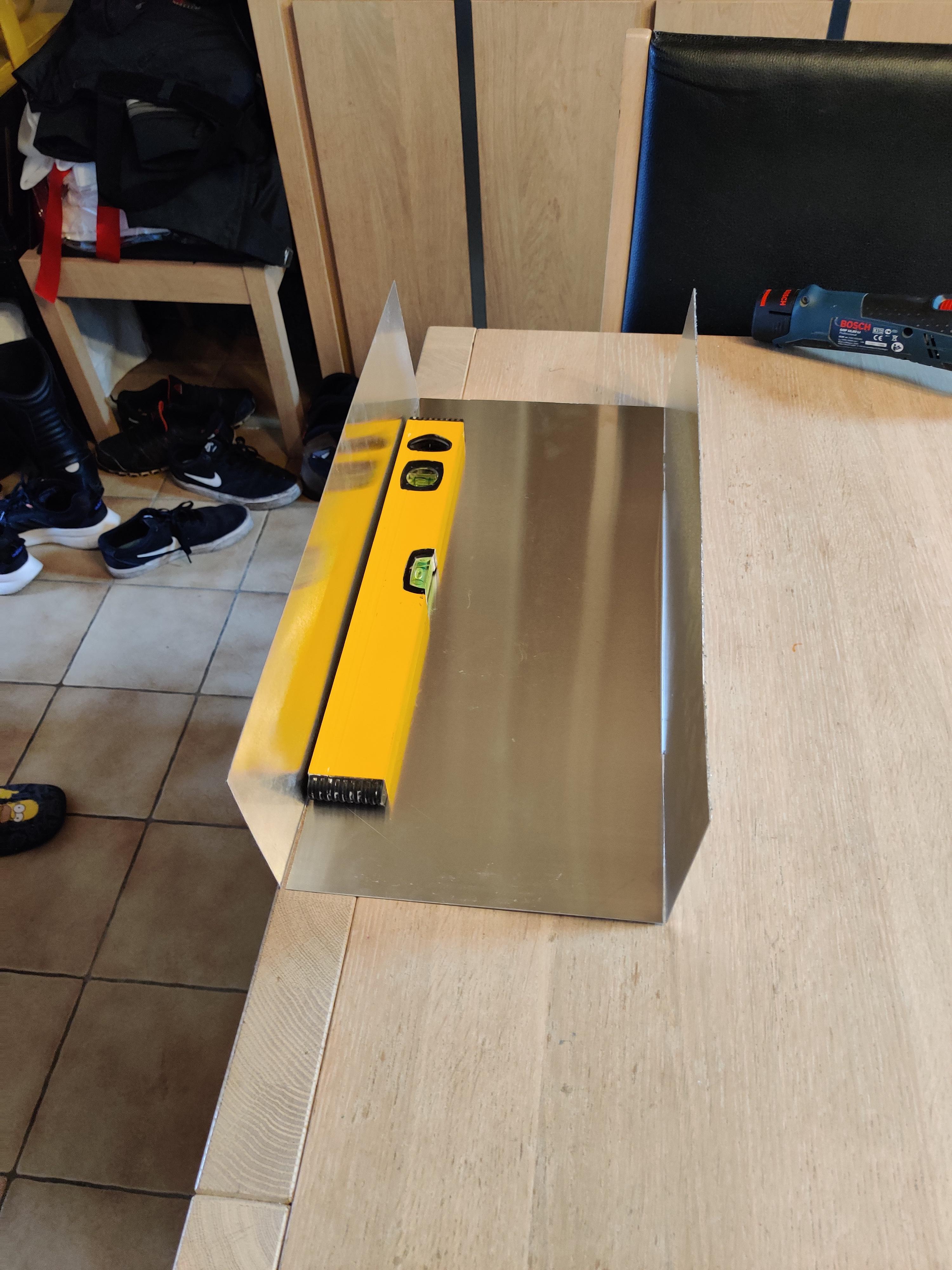
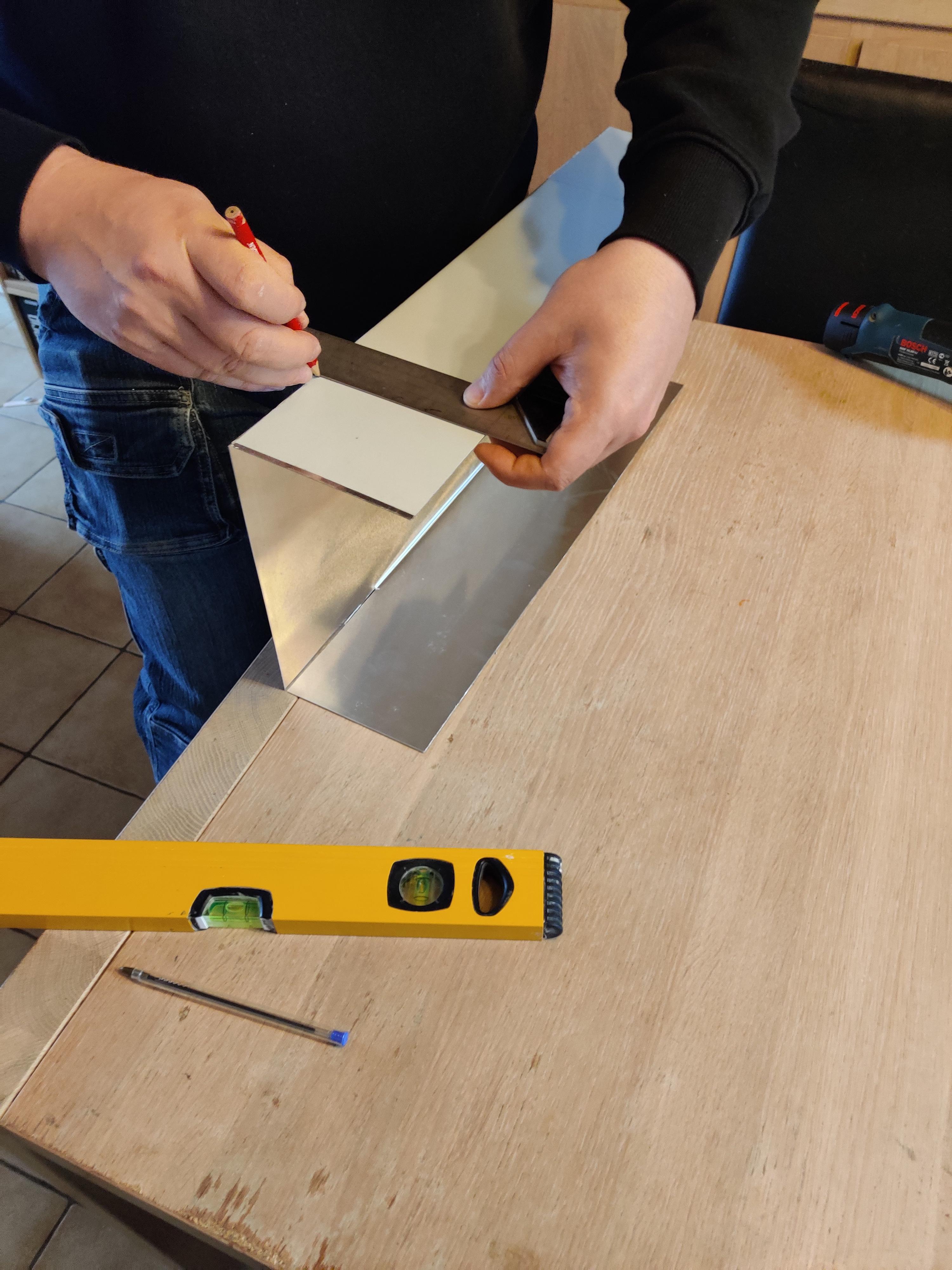
Draw the squares in the aluminum, for this project I used 1 large area of 47 cm, 23 cm for the front of the housing and 12 cm for the sides and the top and bottom of the housing.
Step 2)
Then saw the complete piece out of the aluminum plate.
Step 3)
Saw 2 lines on the 2 side pieces to be able to fold them, do not saw them off!
Step 4)
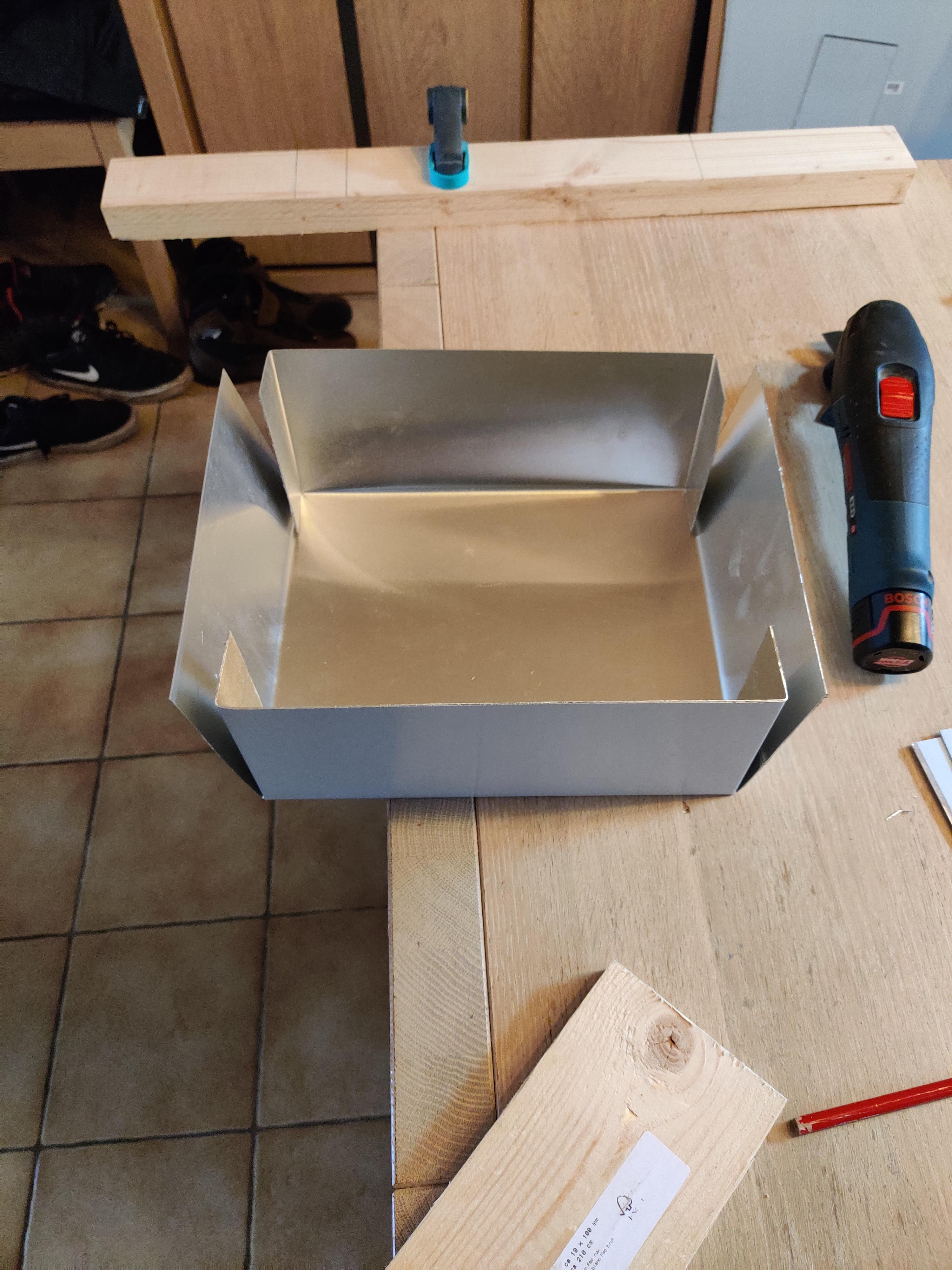
Once it has been sawn, you can start folding it. The intention is to make a rectangle like the one in the pictures.
I used the table to bend it straight.
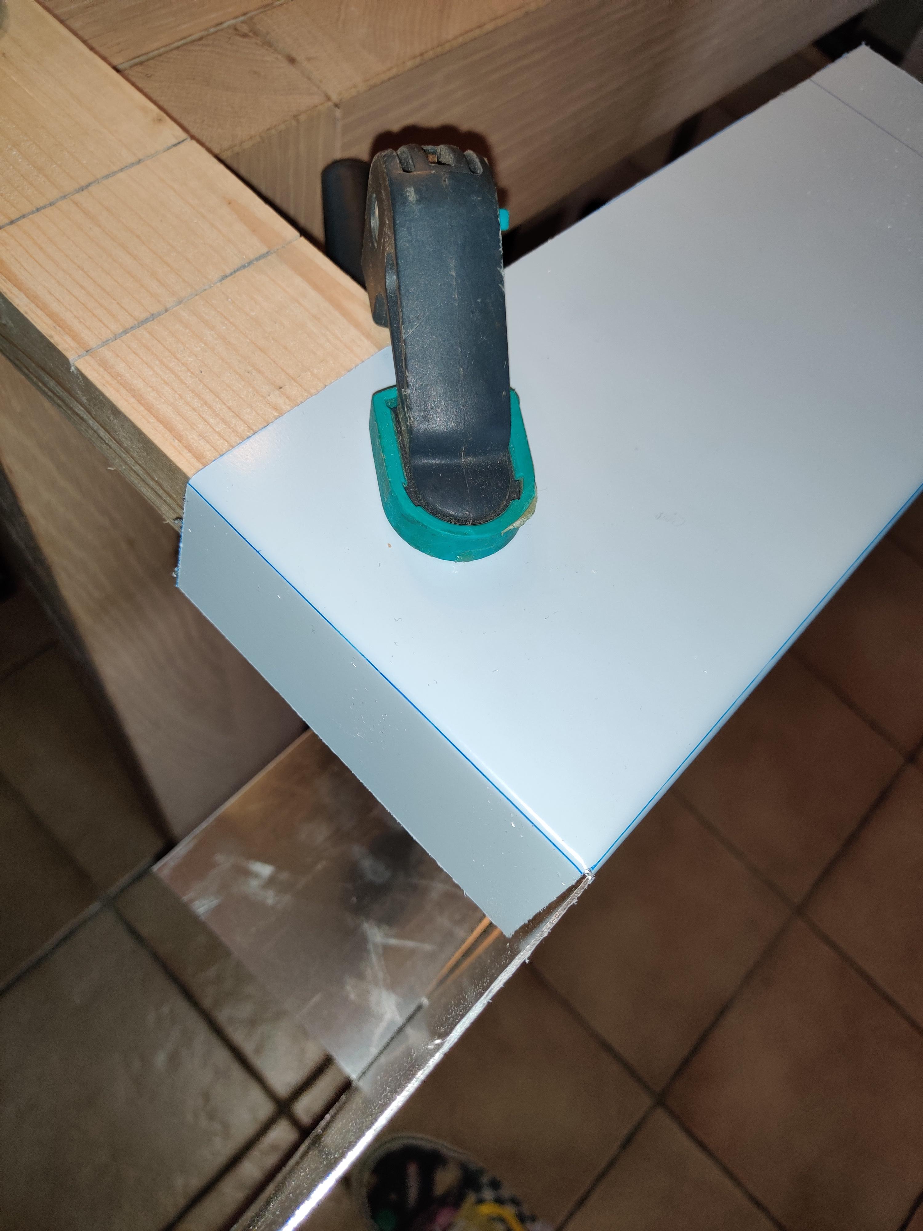
Once I had 2 sides, I drew a small line to be able to fold them in order to make the sides sturdy.
I used a piece of wood to fold these pieces, so that they could be folded easily.
Once you have folded it, you can already see the shape of a box
Step 5)
To attach the housing I used a pair of blind rivet pliers, this way I am sure that the housing will be solid.
!!! First make holes in the housing before attaching it with the blind rivet pliers !!!
Step 6)
I used 4 magnets to be able to hang the housing on the fridge.
Step 7)
For the components I have sawed off the measurements in the housing, note that the keypad only needs a small square because you can easily stick it on the front.
Step 8)
To attach the LCD display I used 2x 3 mm metal screws with nut.
For the OLED display, I used double-sided adhesive tape because I did not have the right screws.
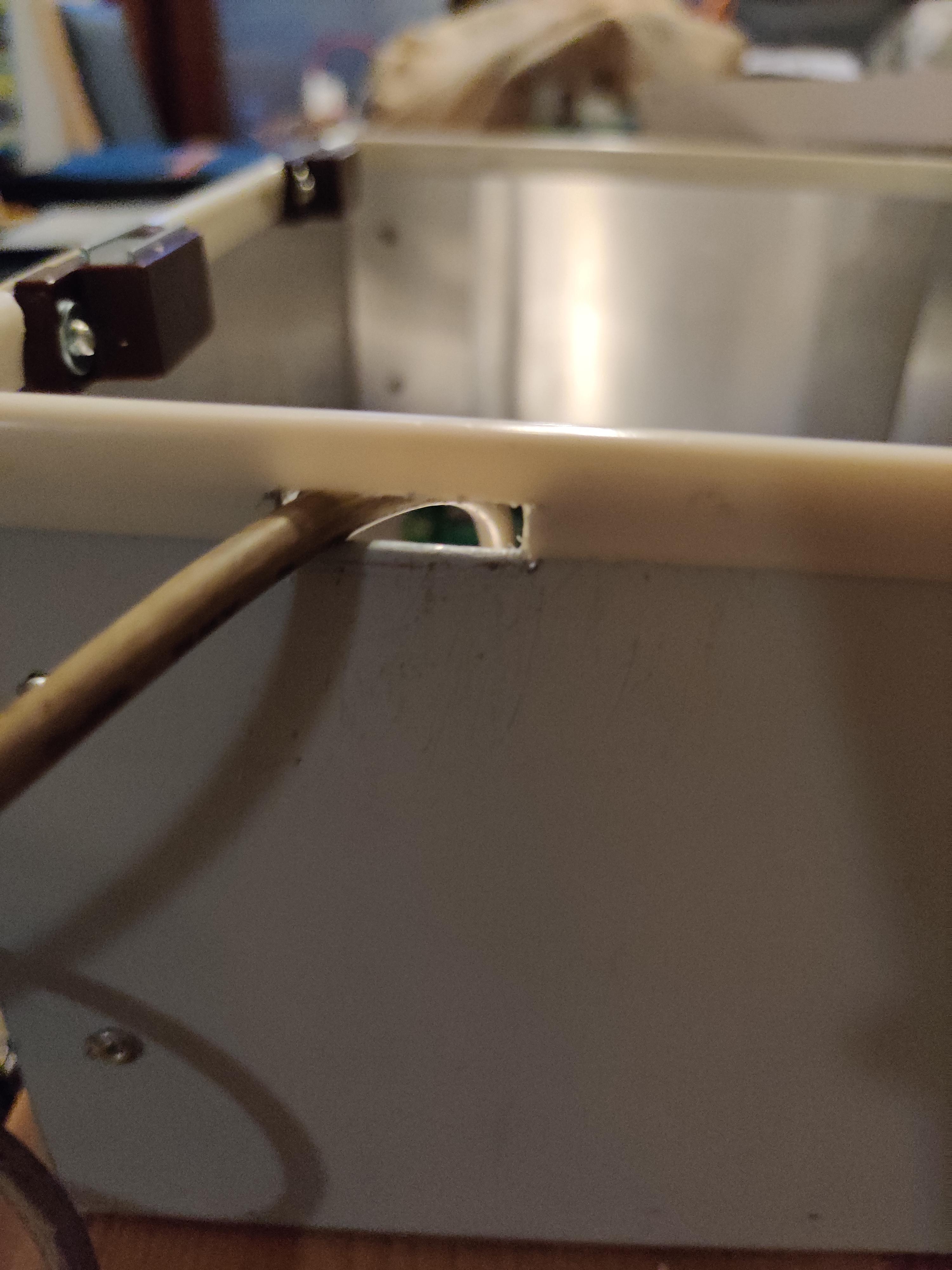
To make it easy to get the cables into the housing, I made a small hole at the bottom of my housing.
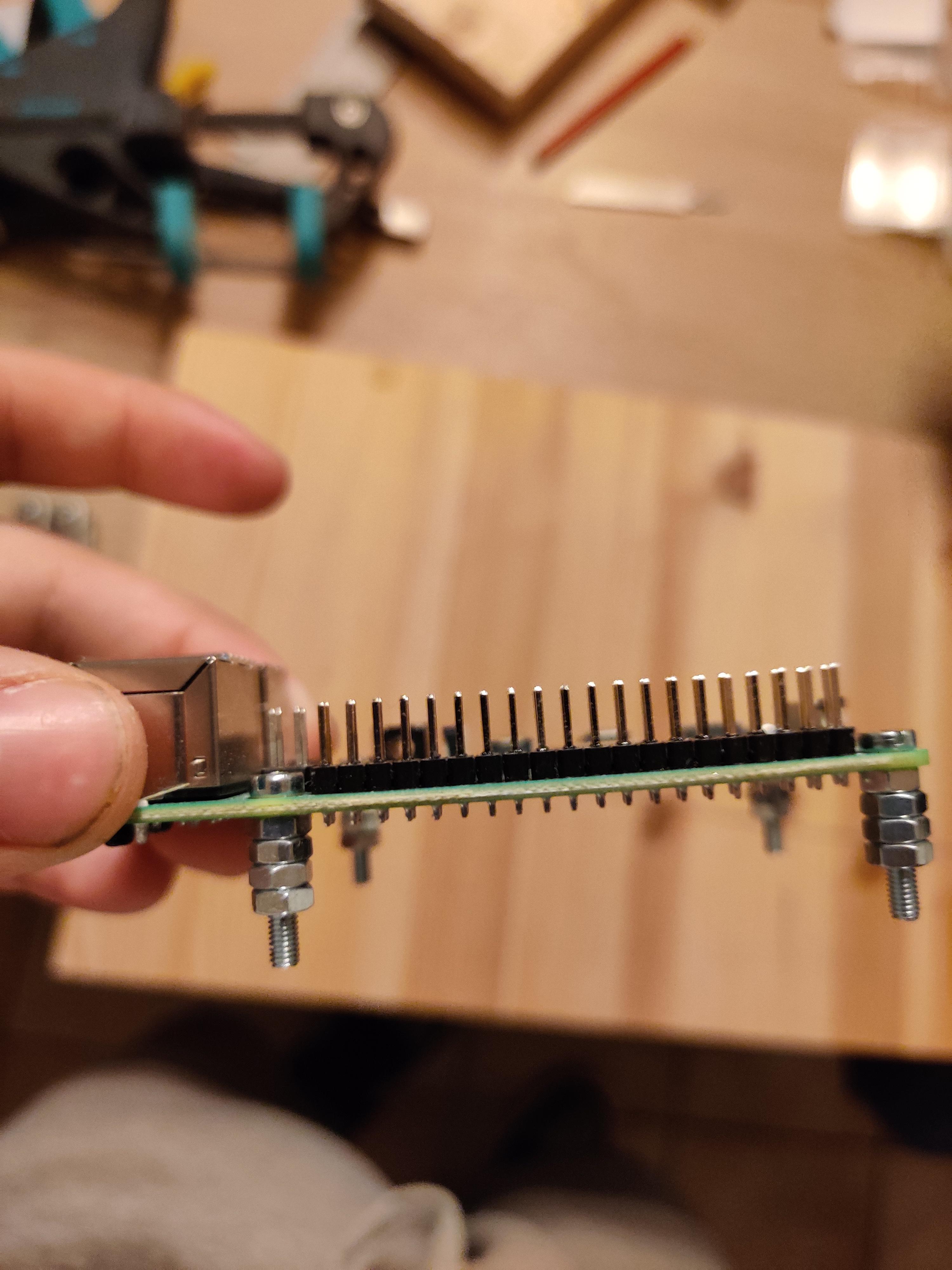
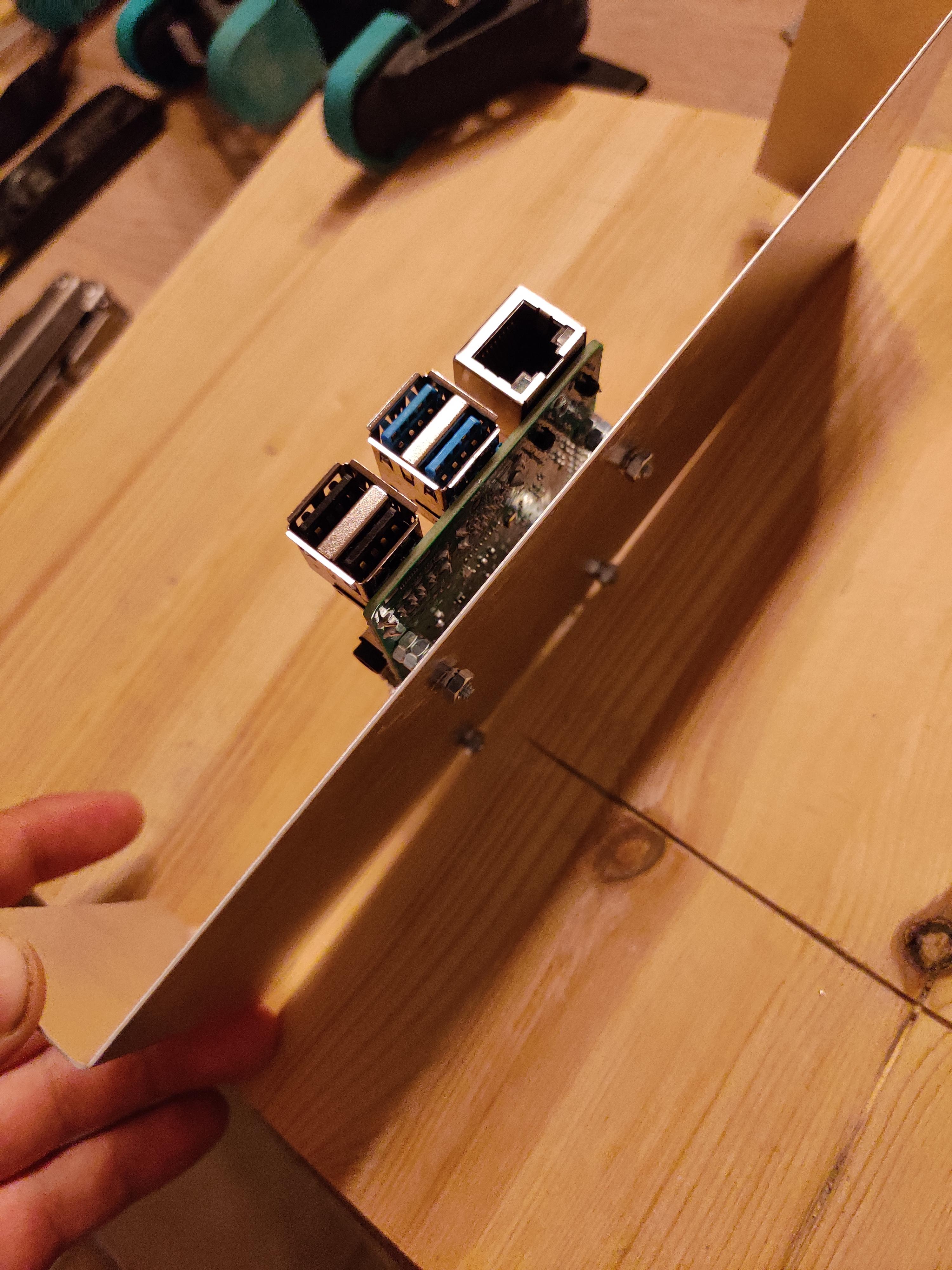
To attach the Raspberry Pi, I used a small piece of aluminum, which I folded at the ends so that I could attach it to the sides. Also, because the Raspberry Pi should not have direct contact with aluminum I used several bolts, so I had a homemade riser.
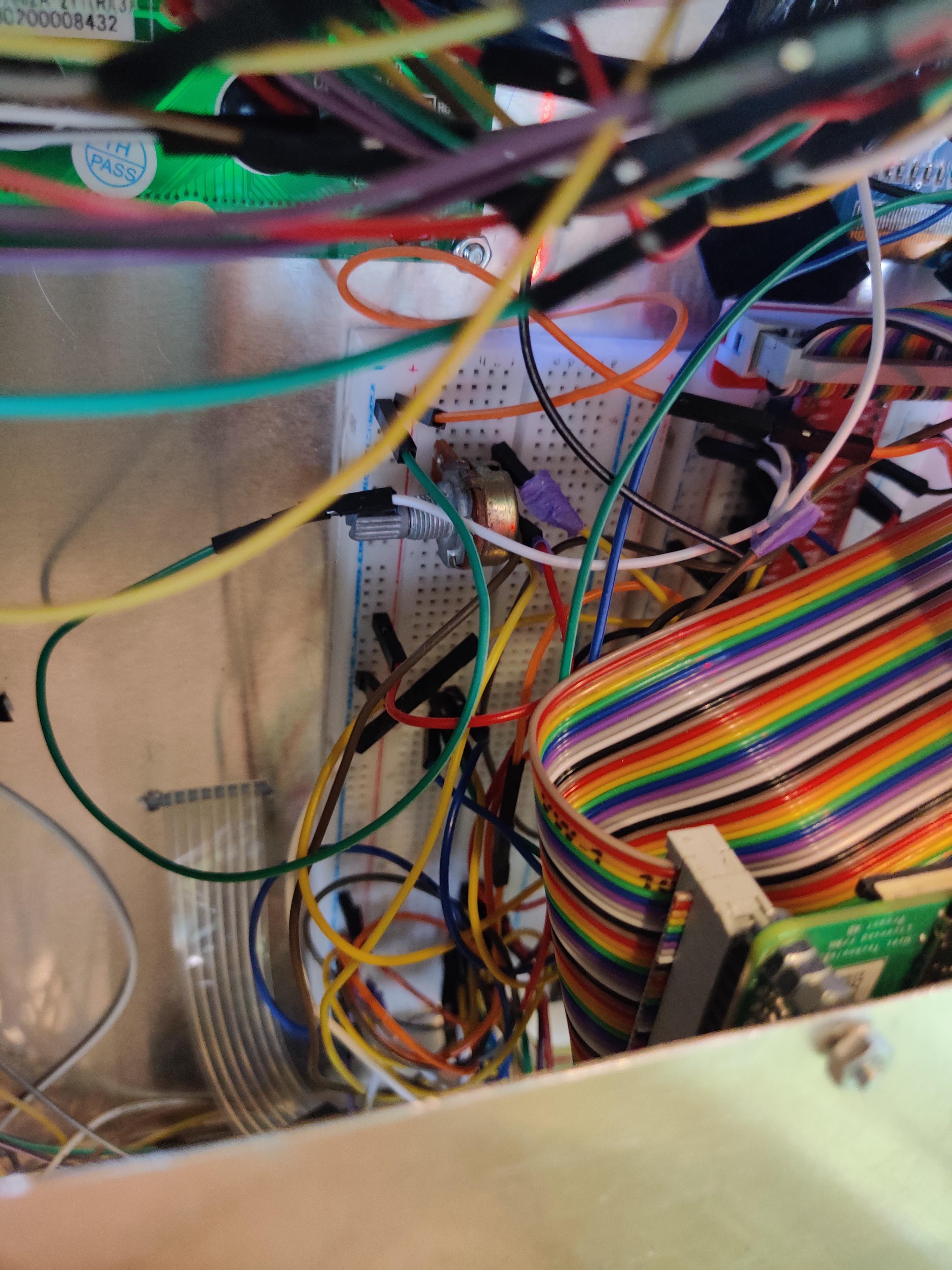
I glued the 2 breadboards to the housing so that I could easily insert my cables and not have to fiddle with the circuit too much.
Step 9)
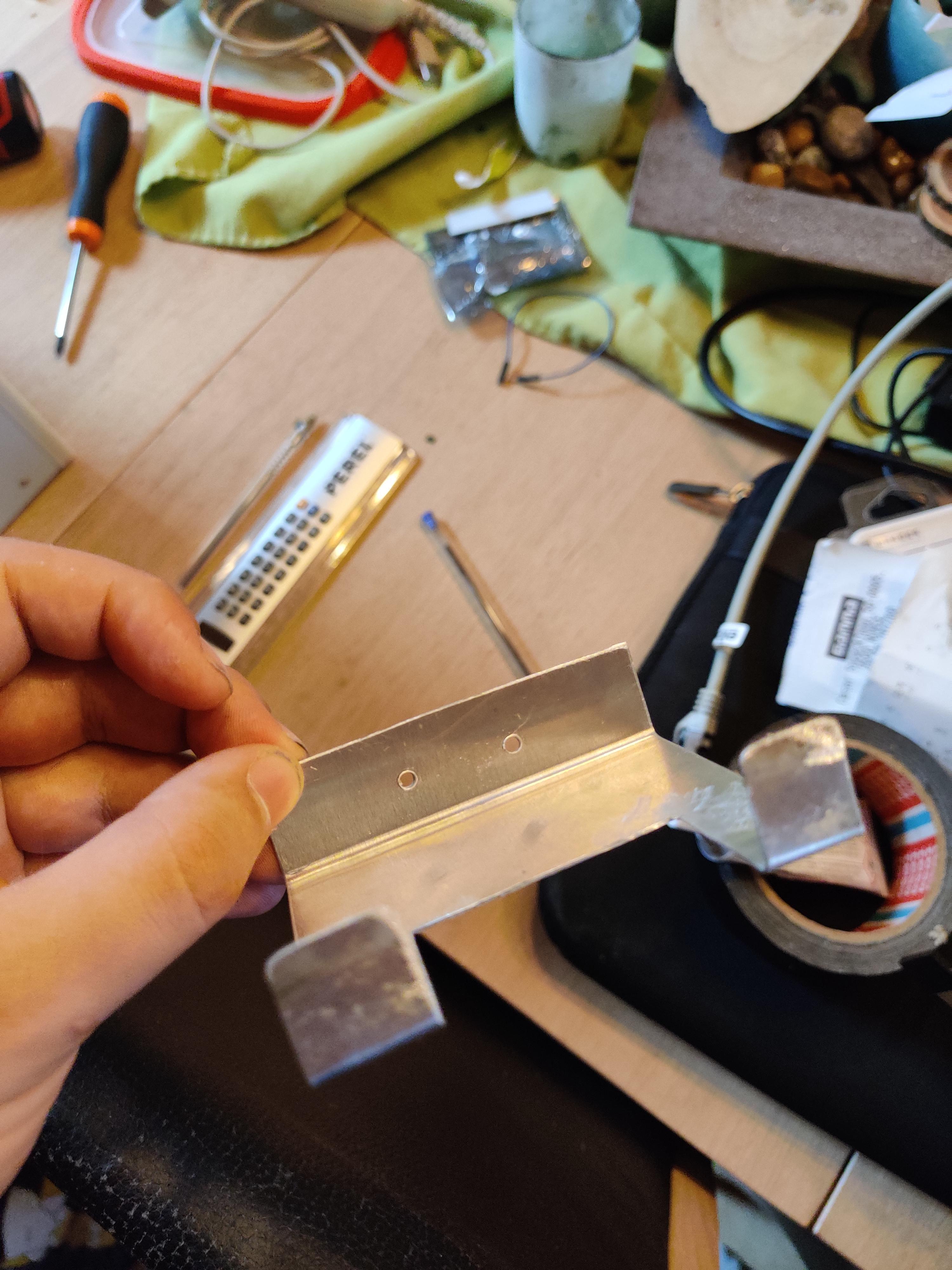
The last piece to attach the barcode scanner I made a support with a small piece of aluminum, I took the width of my barcode scanner and sawed a block out of it, I then folded the 2 ends up, so it could carry the barcode scanner.
Step 10)
Secure that piece with 2 screws, once that is done the housing is ready!
As a finishing touch, I used old backing clamps that I used to use for my papers. You can also use draft excluder if you want something that will stay put.
Extra Info
If you want to modify the code, you should install Visual Studio code, and the add-on to make an ssh connection to your Raspberry Pi.
I will take any tips or ideas to make this project even more fun!
I thought this was a fun project to make, I hope you will too and try to recreate it yourself! :)