Smart Water Bubble Lamp
by Abhinav Padmanabhuni in Workshop > Laser Cutting
2051 Views, 25 Favorites, 0 Comments
Smart Water Bubble Lamp
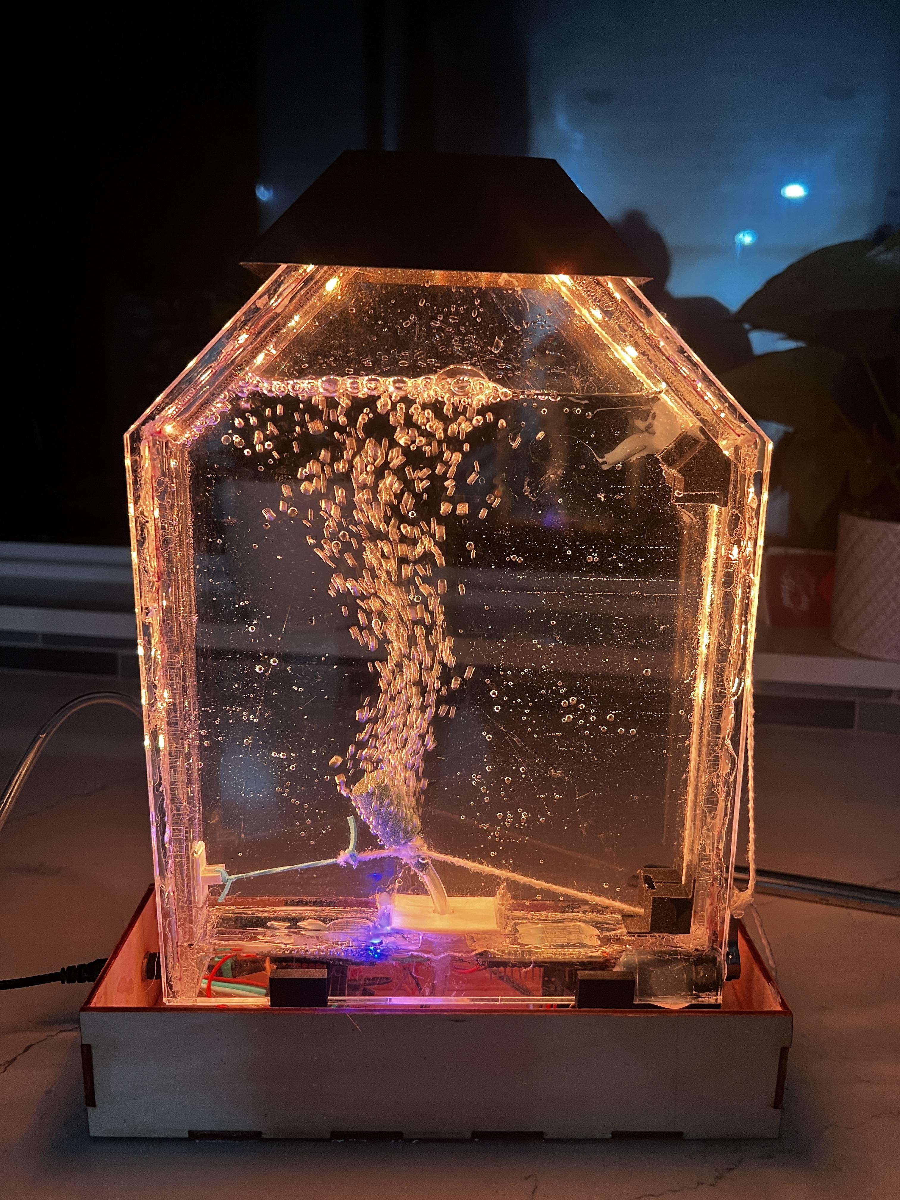
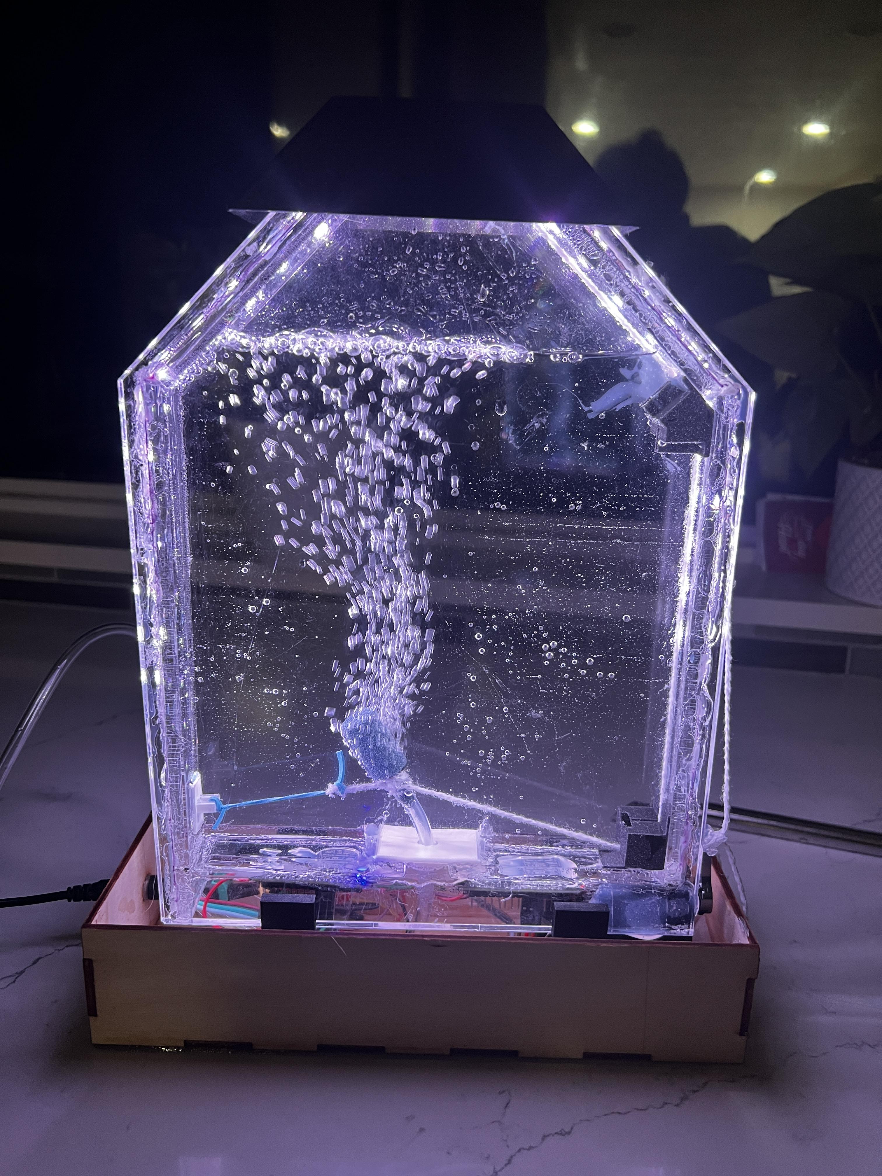
My name is Abhinav Padmanabhuni and I made this project for my Principles of Engineering class with Ms. Berbawy. It took around 5 months to finish because I was only working on it once or twice a week.
I wanted to build this project after I saw an Instructable of a very similar project by V-BOTICS. I saw that there weren't any remakes of the project posted so I decided to keep the project as a reference and build my own version of the bubbles lamp from scratch. One of the major modifications I made was using acrylic instead of glass to make the container.
Special thanks to Ms. Berbawy, our POE teacher!
Supplies
Materials:
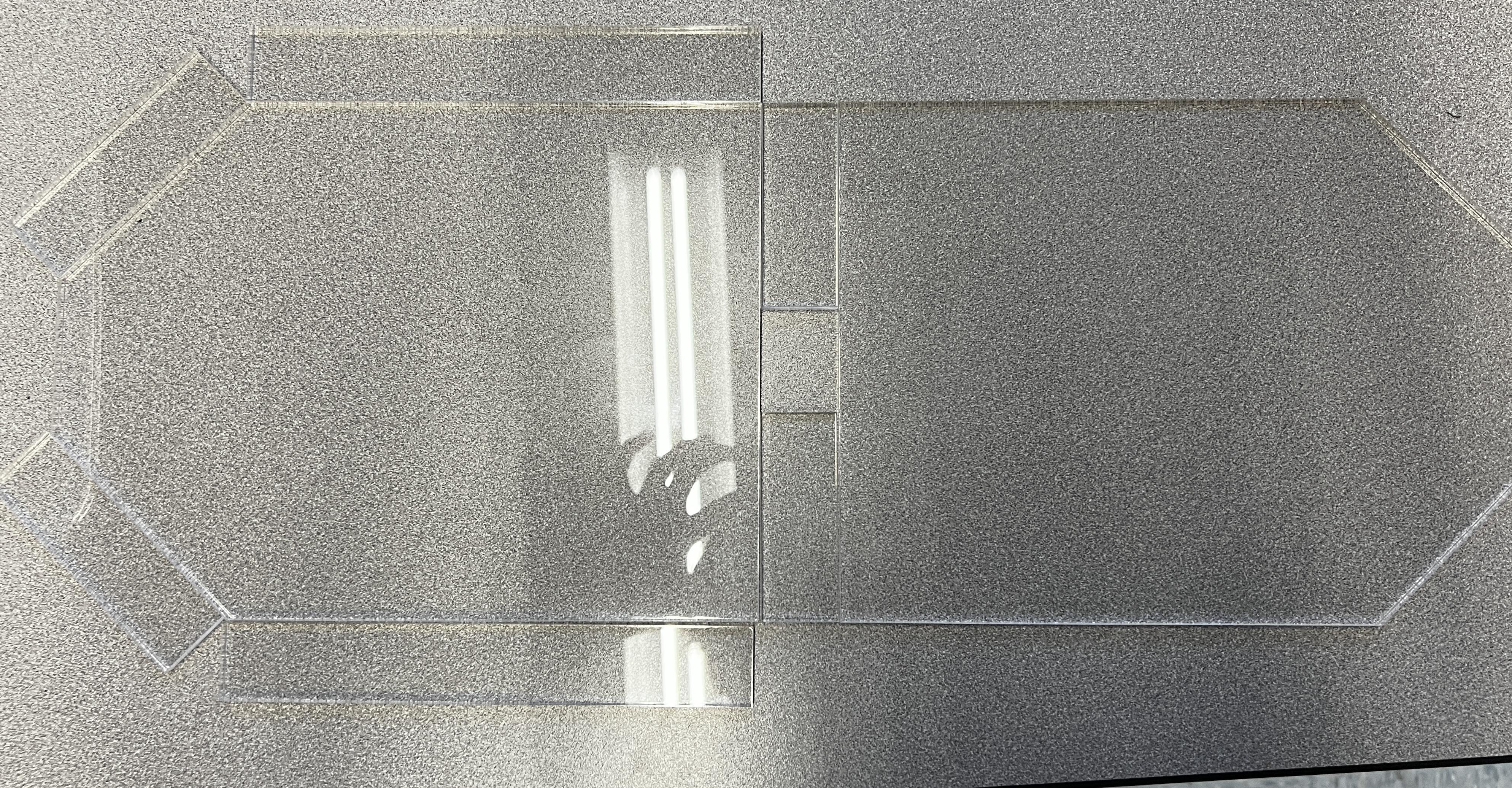
- 1/4 inch acrylic sheets
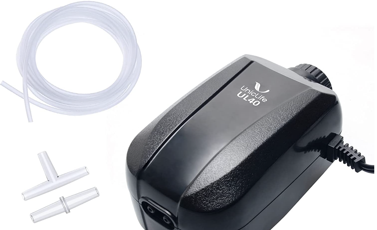
- Aquarium Air Pump + Pipe
- Bubble Release Stones
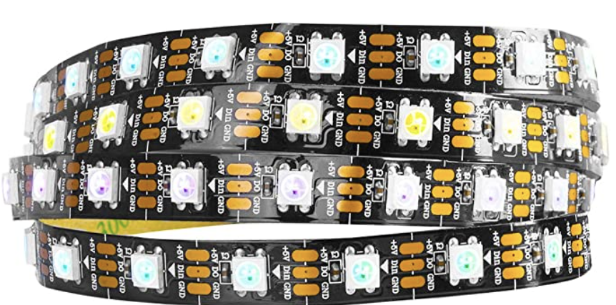
- Individually addressable LED strip (ws2812b)
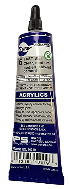
- Acrylic Cement
- Rubberbands
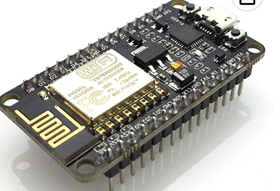
- Node MCU ESP8266 wifi-card
- Arduino nano (any microcontroller) (another Node MCU)
- String
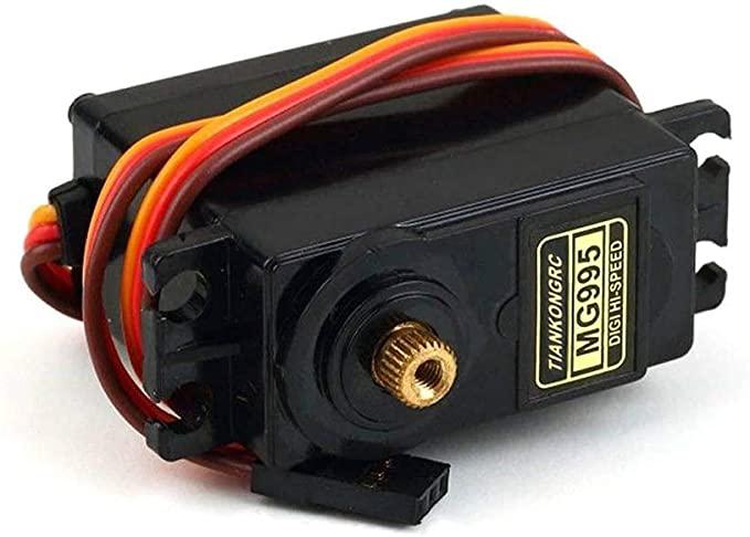
- Servo Motor
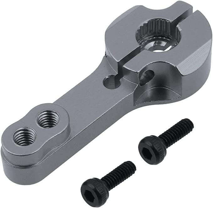
- Adjustable aluminum Servo Horn
- Wire
Tools:
- Hot glue gun
- Soldering iron
- 3D Printer
- Laser Cutter
3D Printed Parts (printed with Prusa Mini+)
Assemble the Acrylic Frame
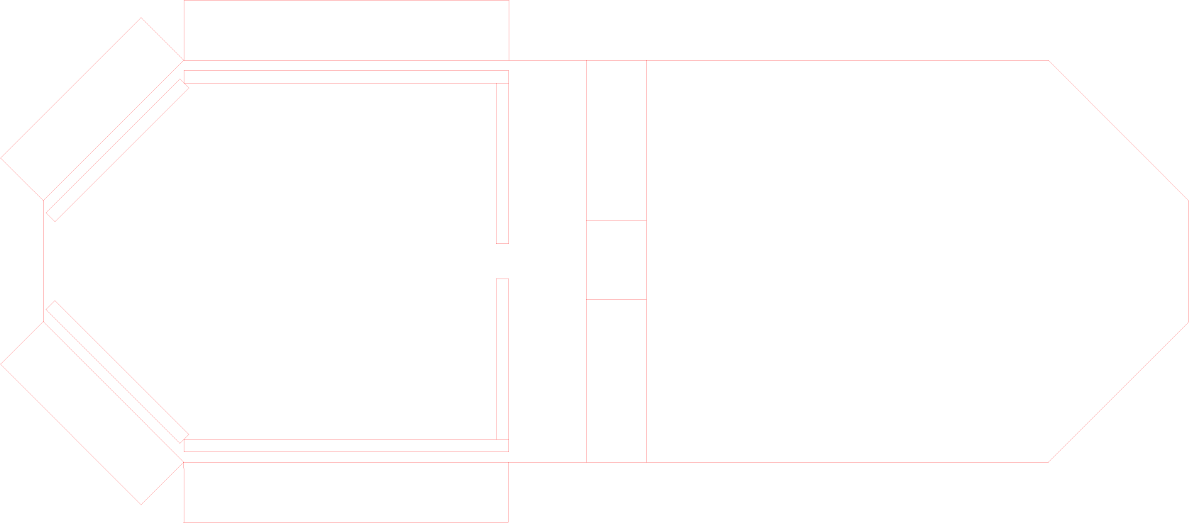
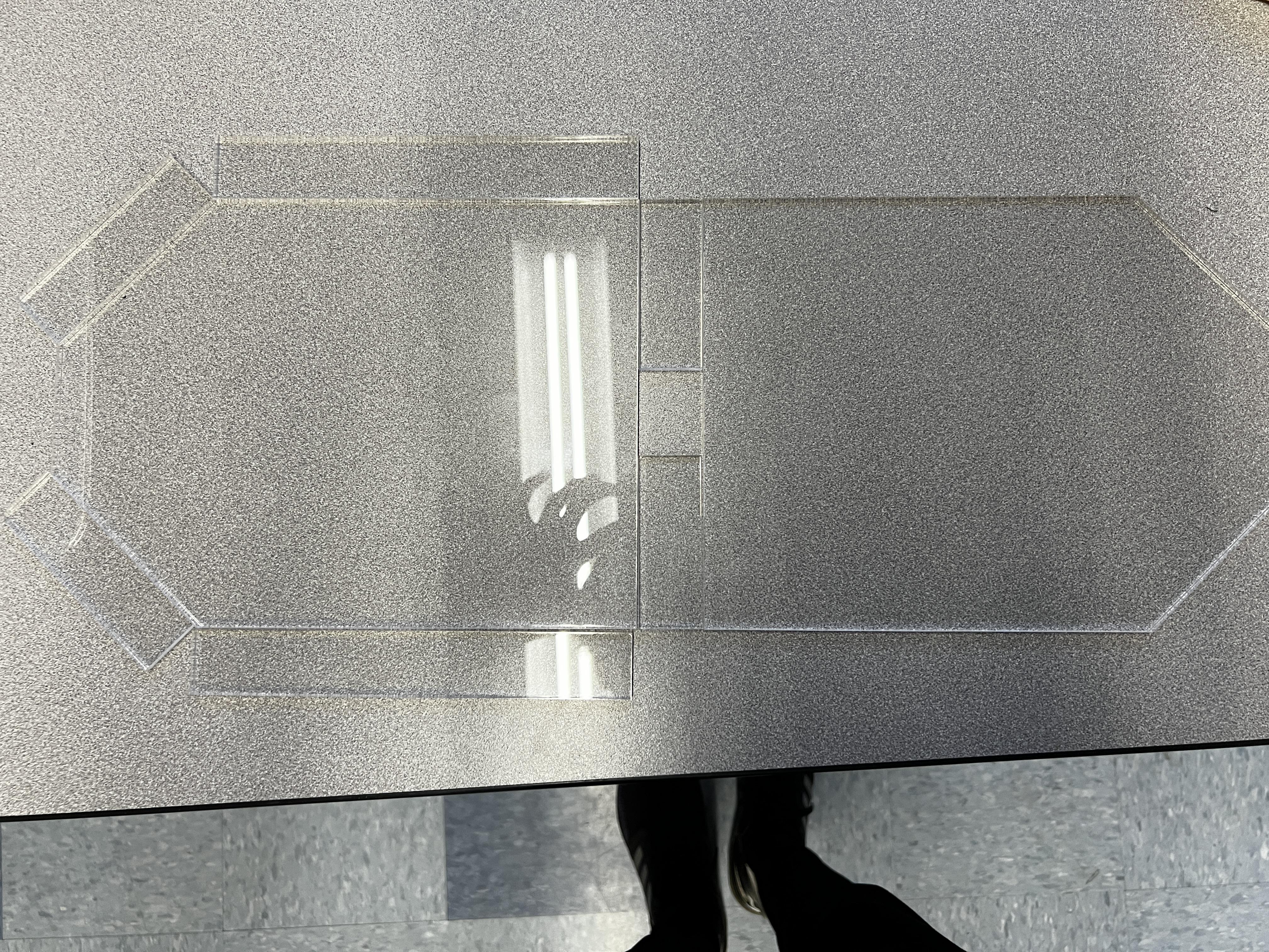
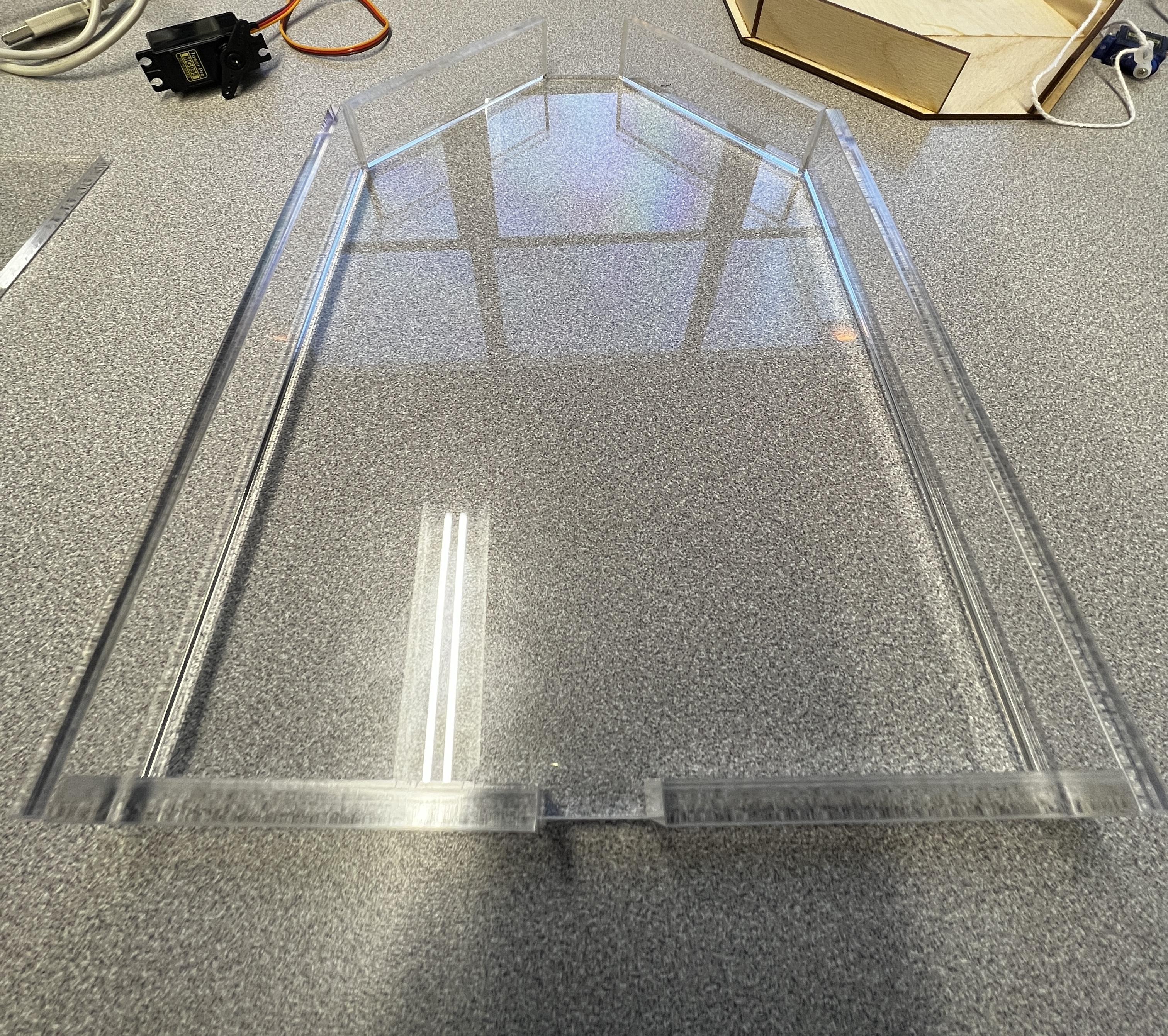
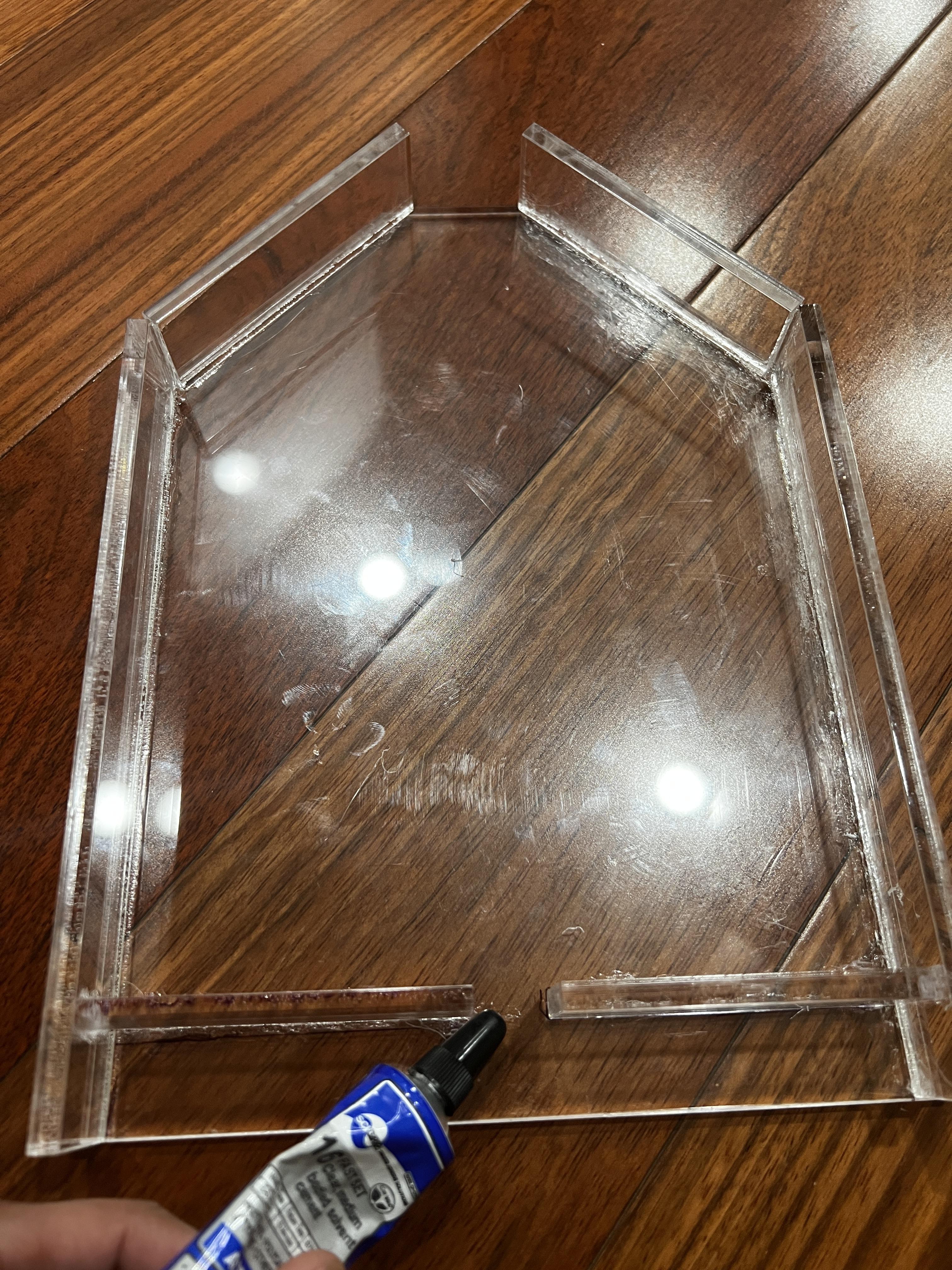
- Laser cut an acrylic sheet using the illustrator file below.
- Use acrylic cement to attach the 4 acrylic pieces to create the structure shown in (Figure 02 and 03). Acrylic cement is crucial as it is able to chemically bond the acrylic pieces together. Since the container will be filled with water, it's important that the acrylic is securely attached to prevent any leaks.
- Allow the frame to dry for about 24 hours for 100% strength.
Downloads
Water Bubbles Mechanism (Pt. 1)
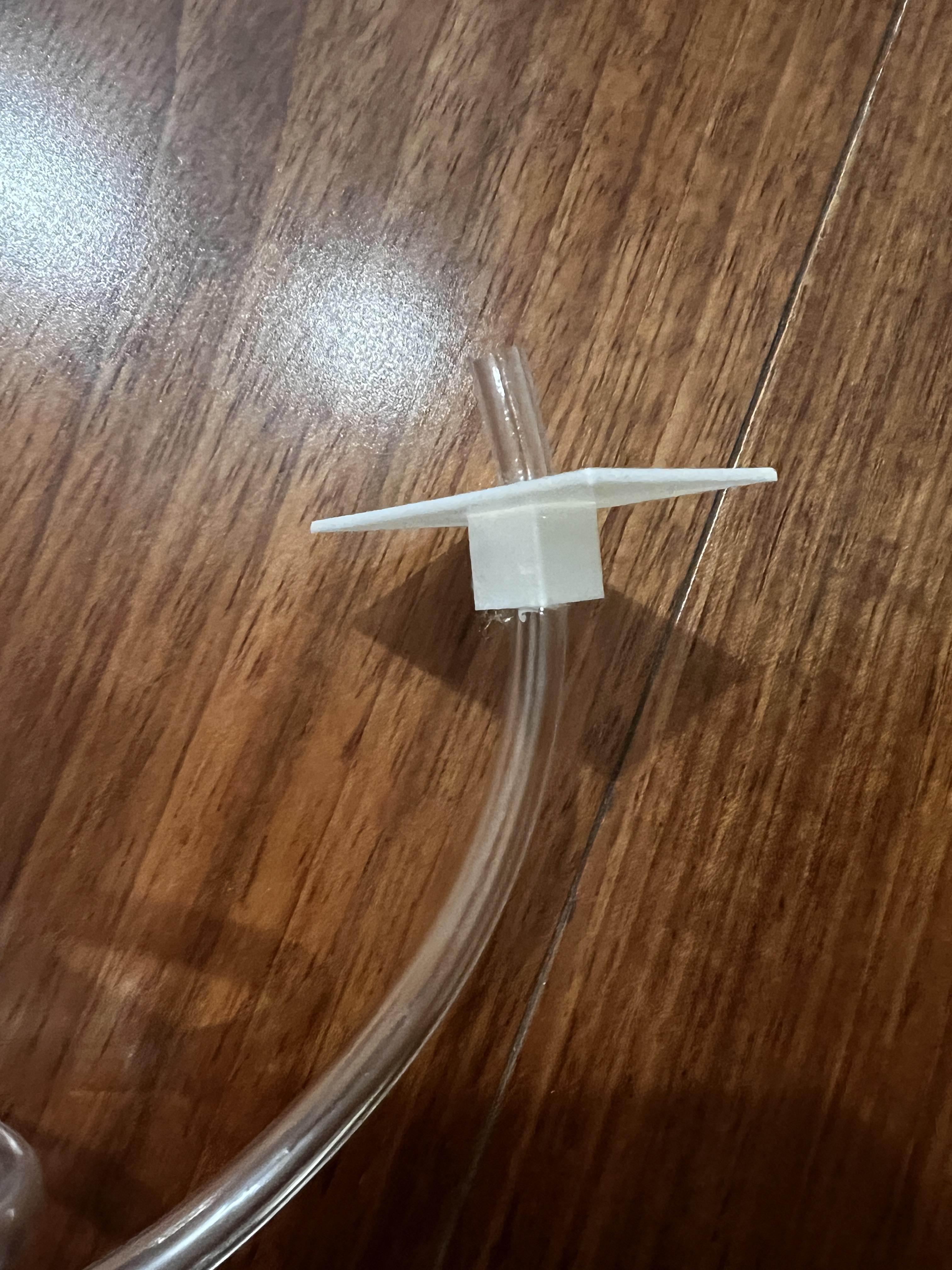
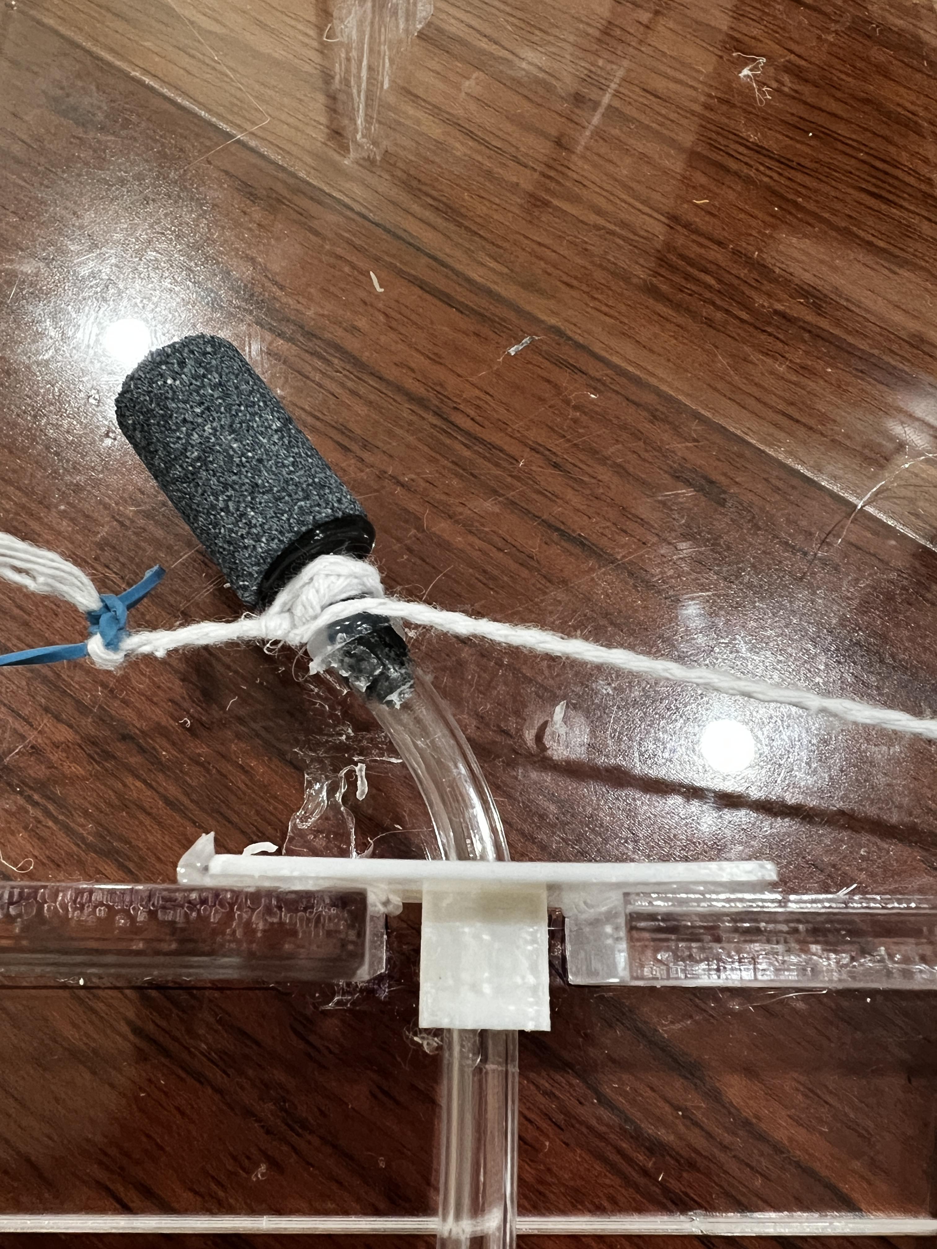
To mount the air tube/pipe and bubble release air stone, follow these steps:
- Fit the aquarium air pipe into the hole of the WL008 3d printed component
- Attach the bubble release air stone to the aquarium air tube/pipe, as depicted in Figure 02.
- Use acrylic cement, to fix the WL008 3d printed component to the acrylic frame. Ensure that they are securely attached and properly positioned to effectively release bubbles into the water.
Water Bubbles Mechanism (Pt. 2)
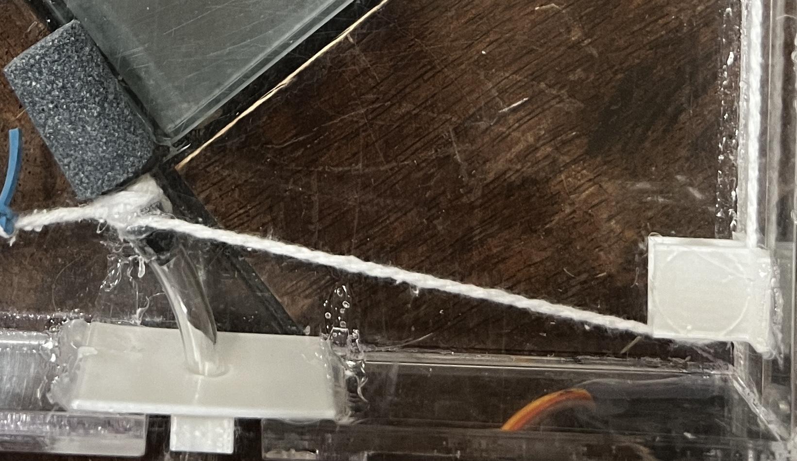
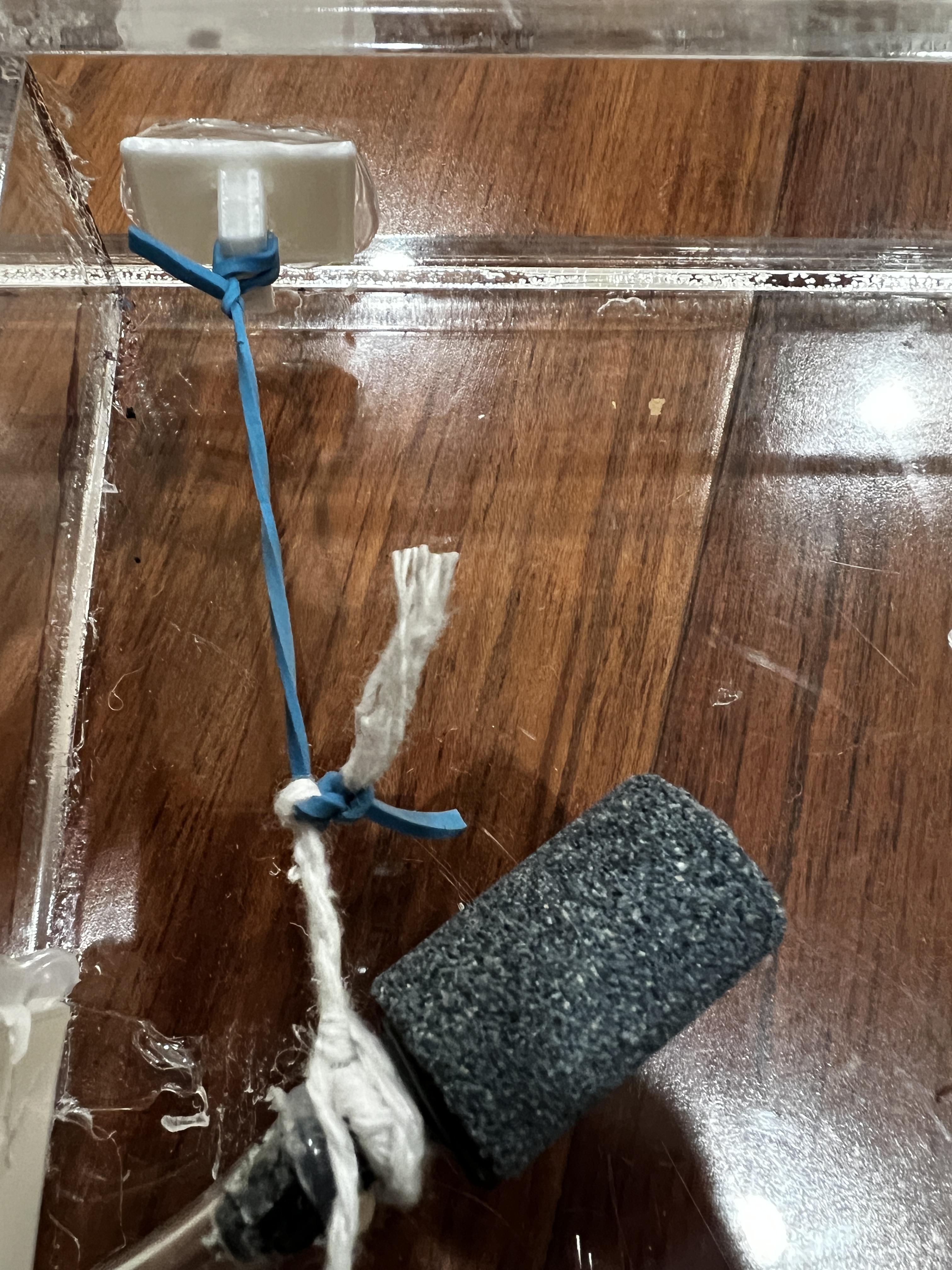
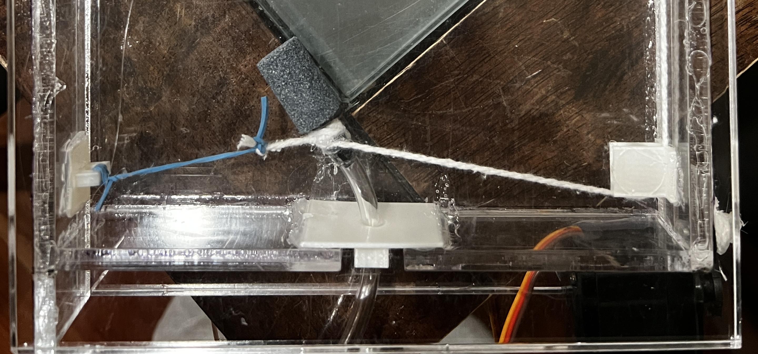
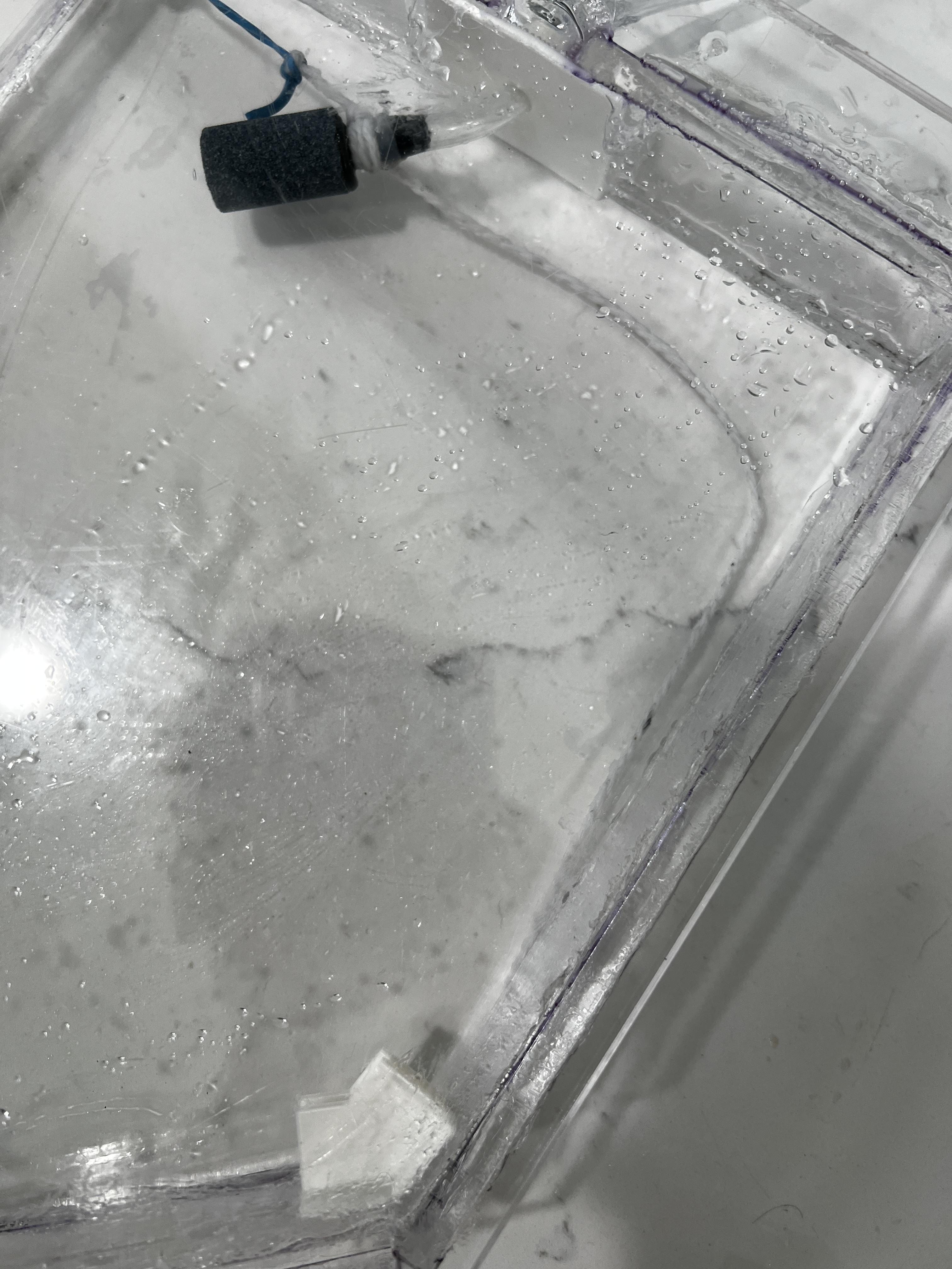
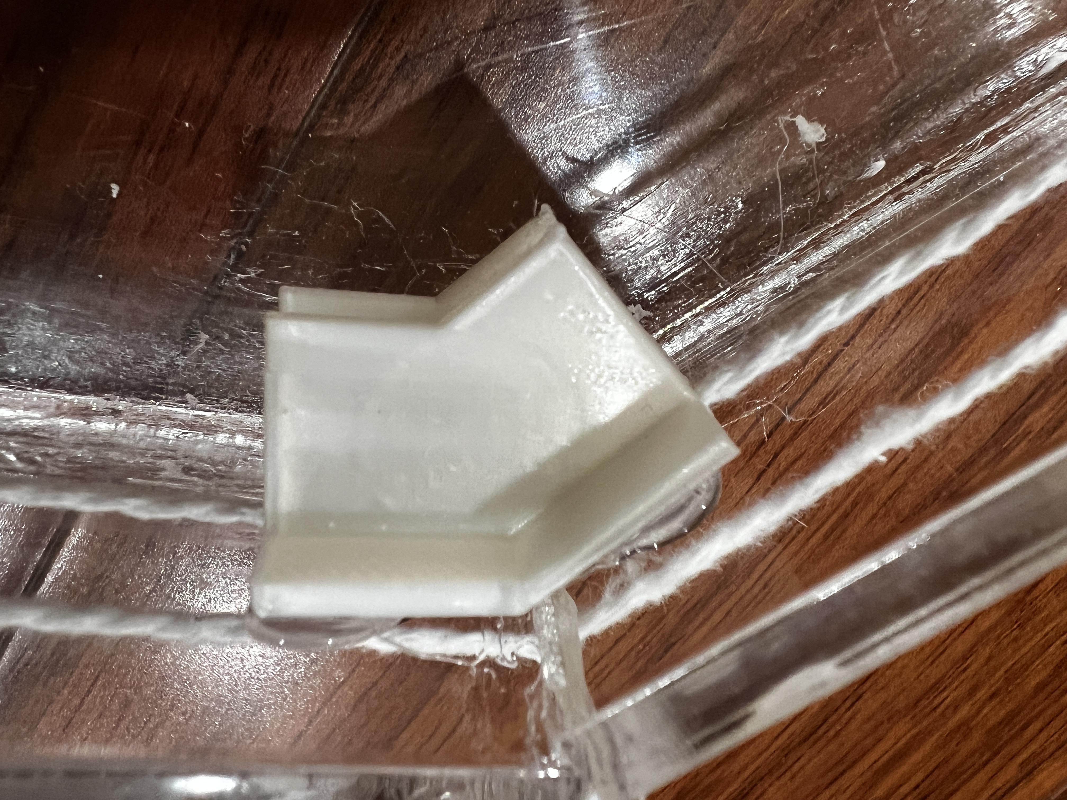
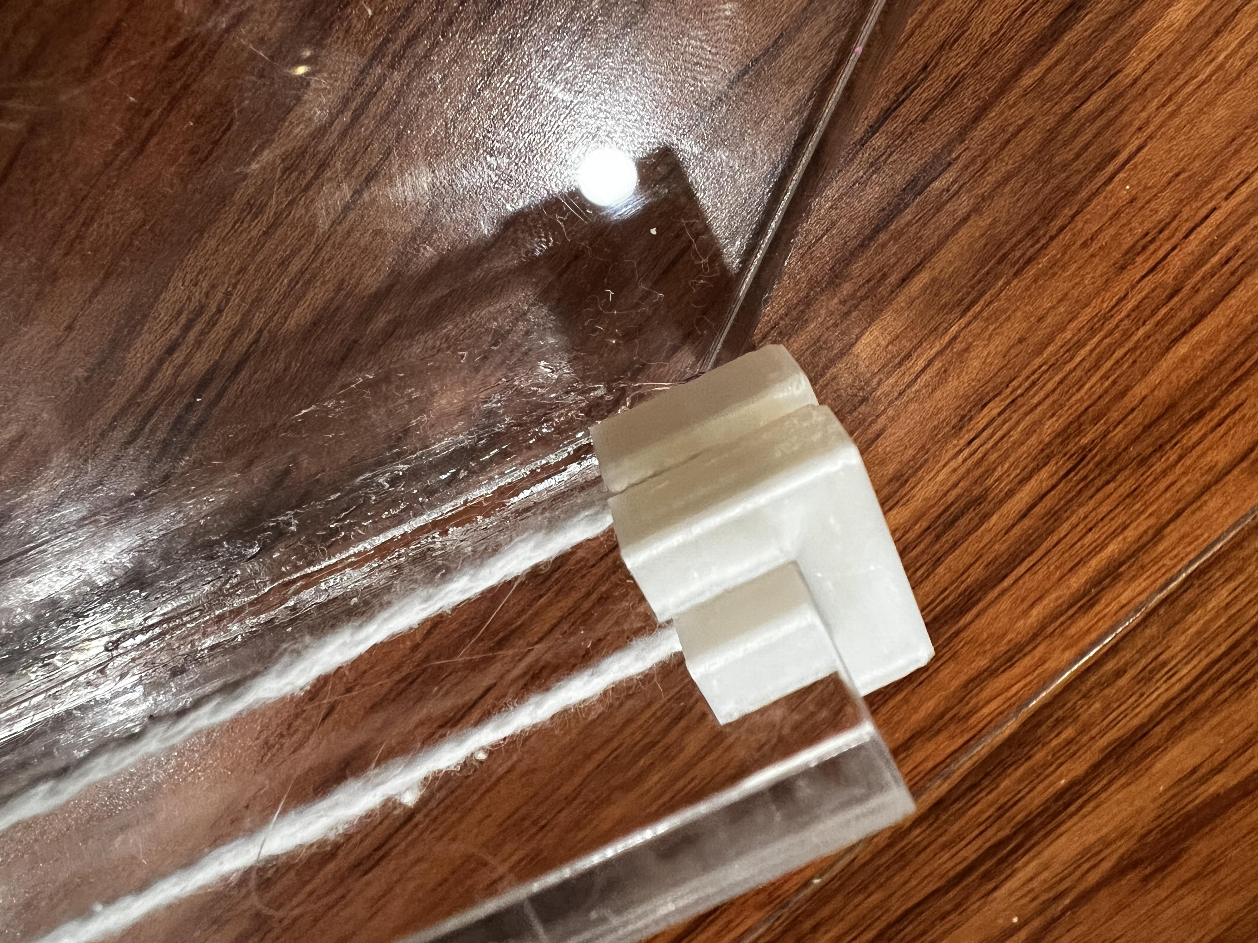
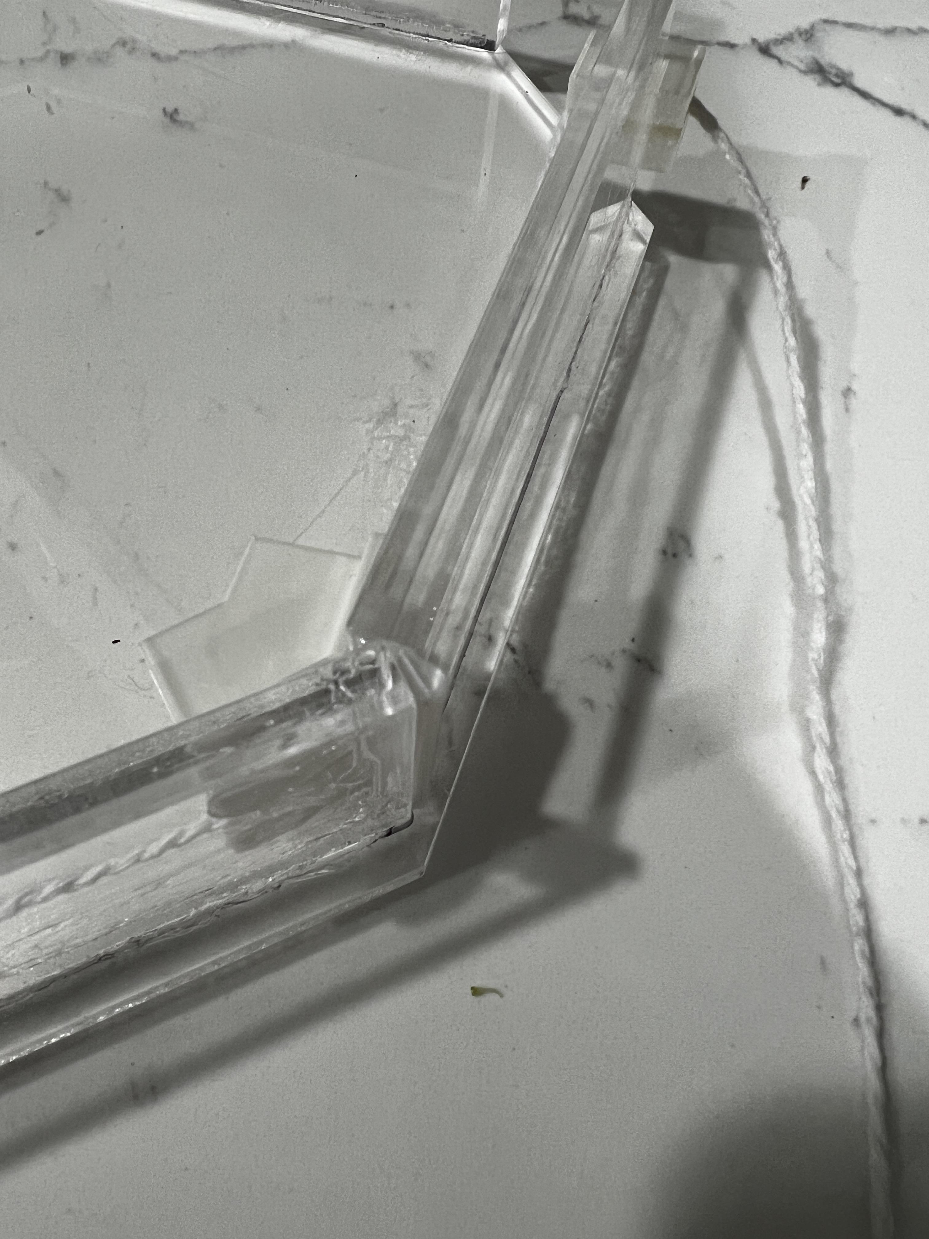
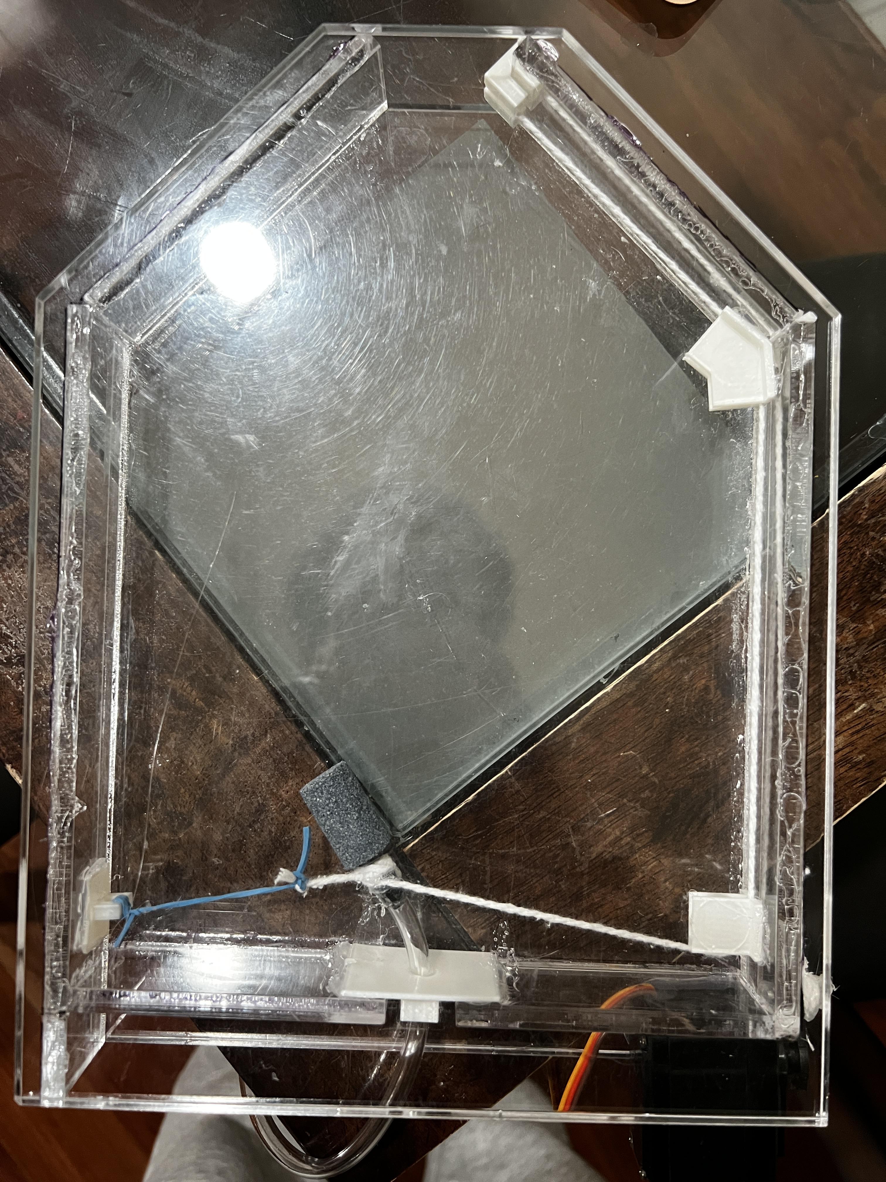
To assemble the WL004, WL005, WL007 and WL009 3D printed parts, as well as the rubber band, follow these steps:
- Put string through the WL004 3D printed part, as shown in Figure 01.
- Attach the WL004 part to the right side wall of the acrylic frame using acrylic cement (See Figure 1 for placement).
- Tie the string around the bubble release stone mechanism
- Connect rubber band to the WL007 3D printed part, as shown in Figure 02 and glue it to the left side of the wall.
- Tie the rubber band and the string on the bubble release stone to ensure that there is enough tension to move the component to the left a bit
- Then, send the string through the WL009 part (position shown in Figure 4 & 5) and glue it to the acrylic frame
- At the top, attach the WL005 3d printed part to the side and run the string through it (Figure 6 & 7)
The assembled version can be seen in the last image.
Fix the Top Acrylic Frame
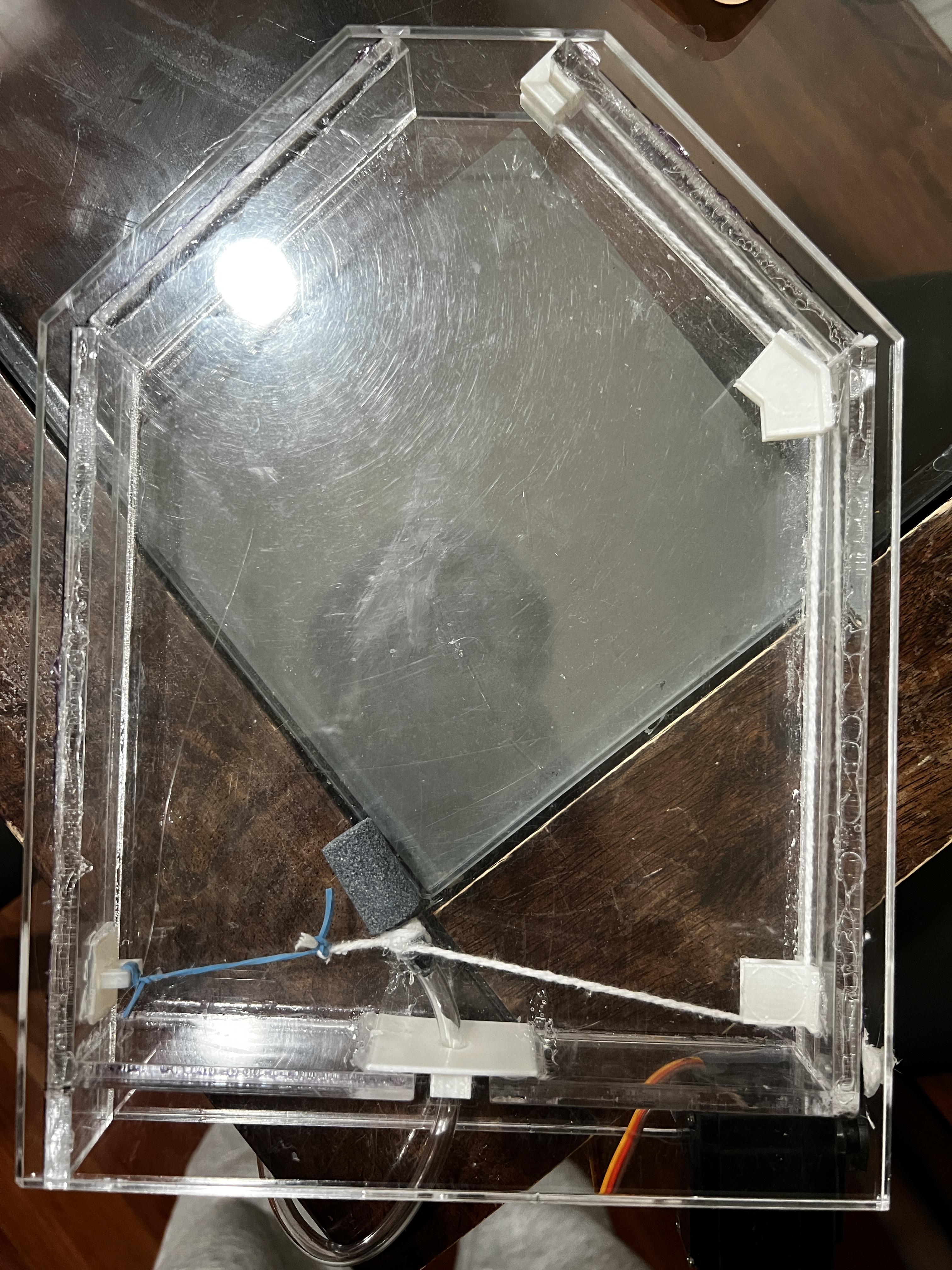
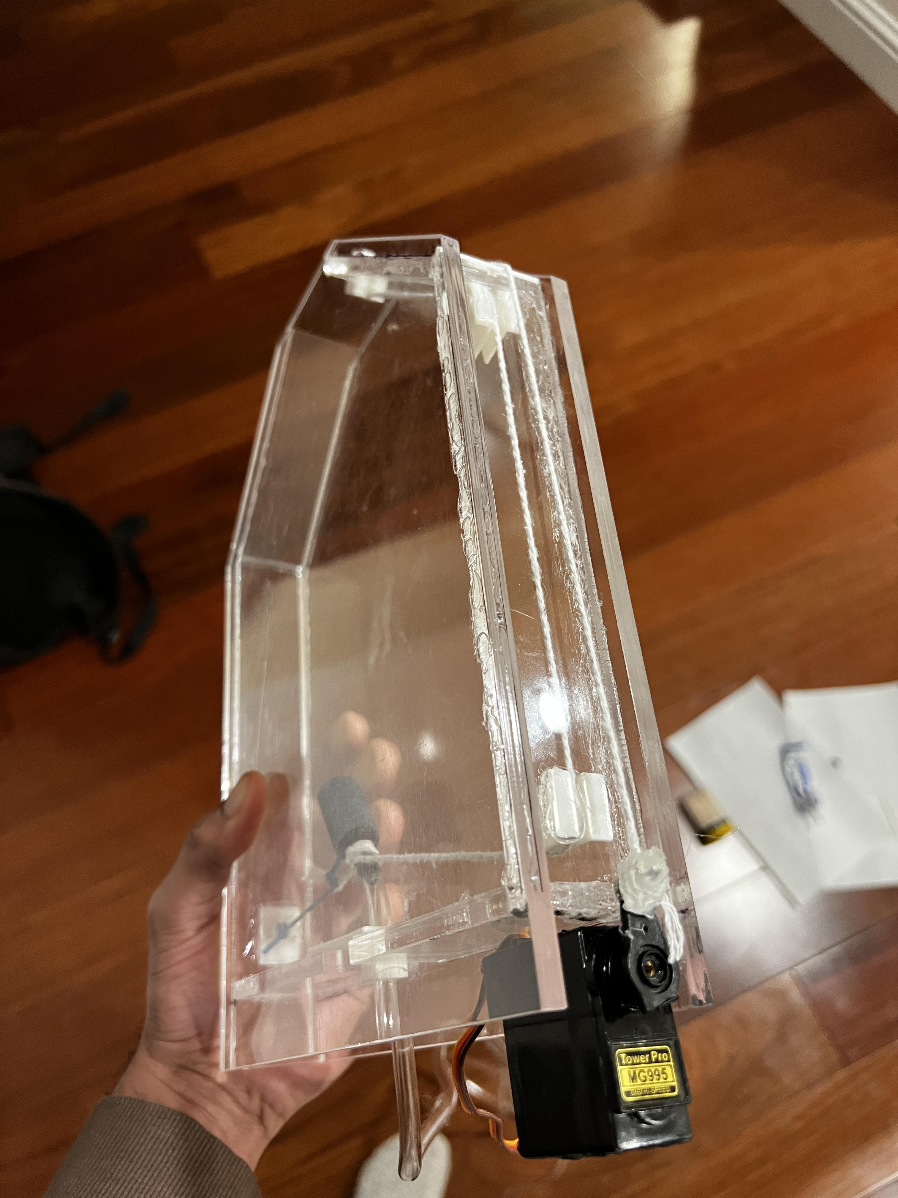
To attach the acrylic frame to the acrylic base:
- Use acrylic cement along the top edge of the acrylic frame. It's important to ensure that the frame is well-sealed, as it will be filled with water.
- Place the top acrylic frame onto the base container, making sure that it is level and aligned. Let the cement dry for approximately 24 hours to ensure that it is completely cured and that the acrylic frame is firmly attached to the base.
Surround With LEDs
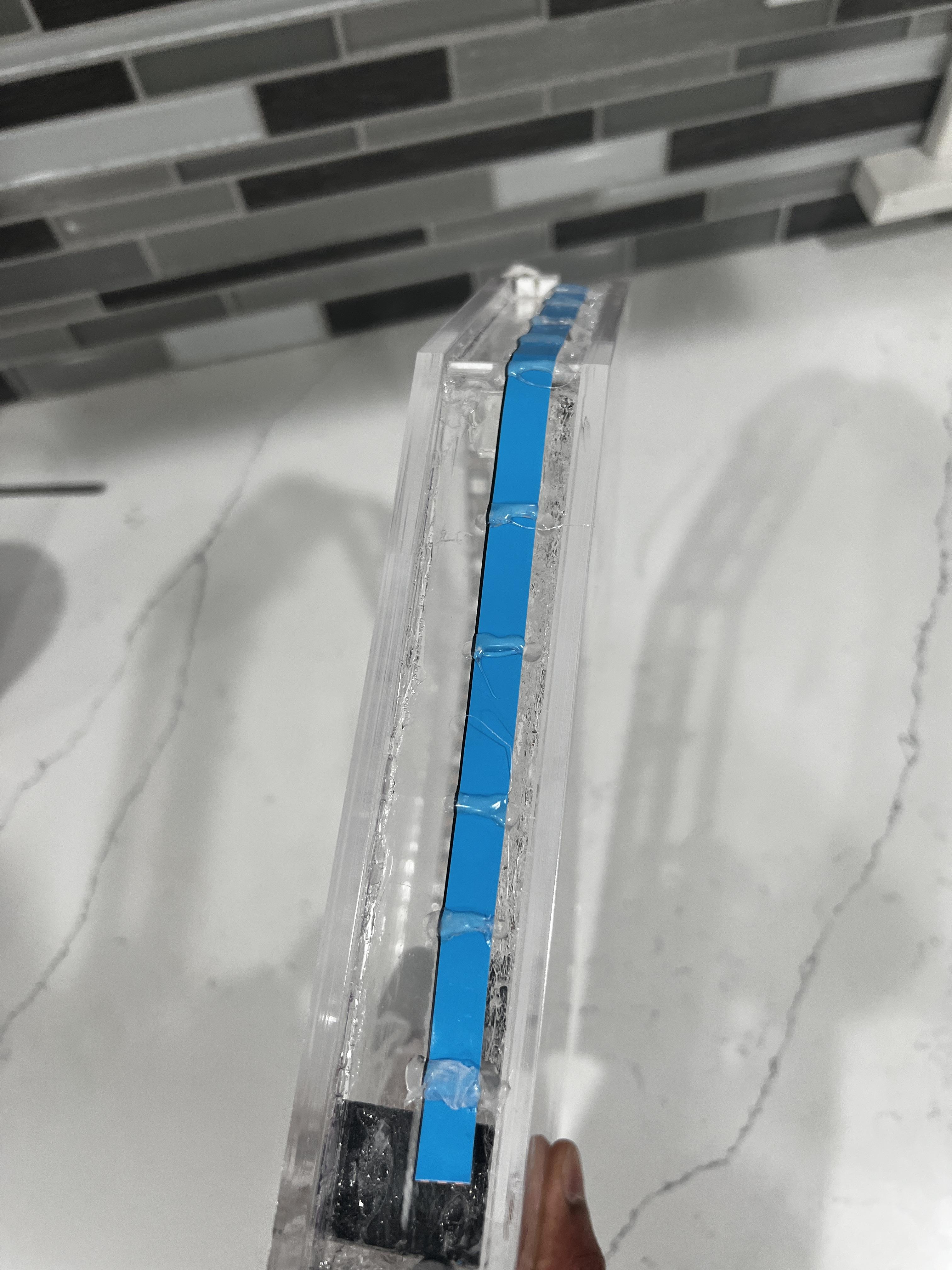
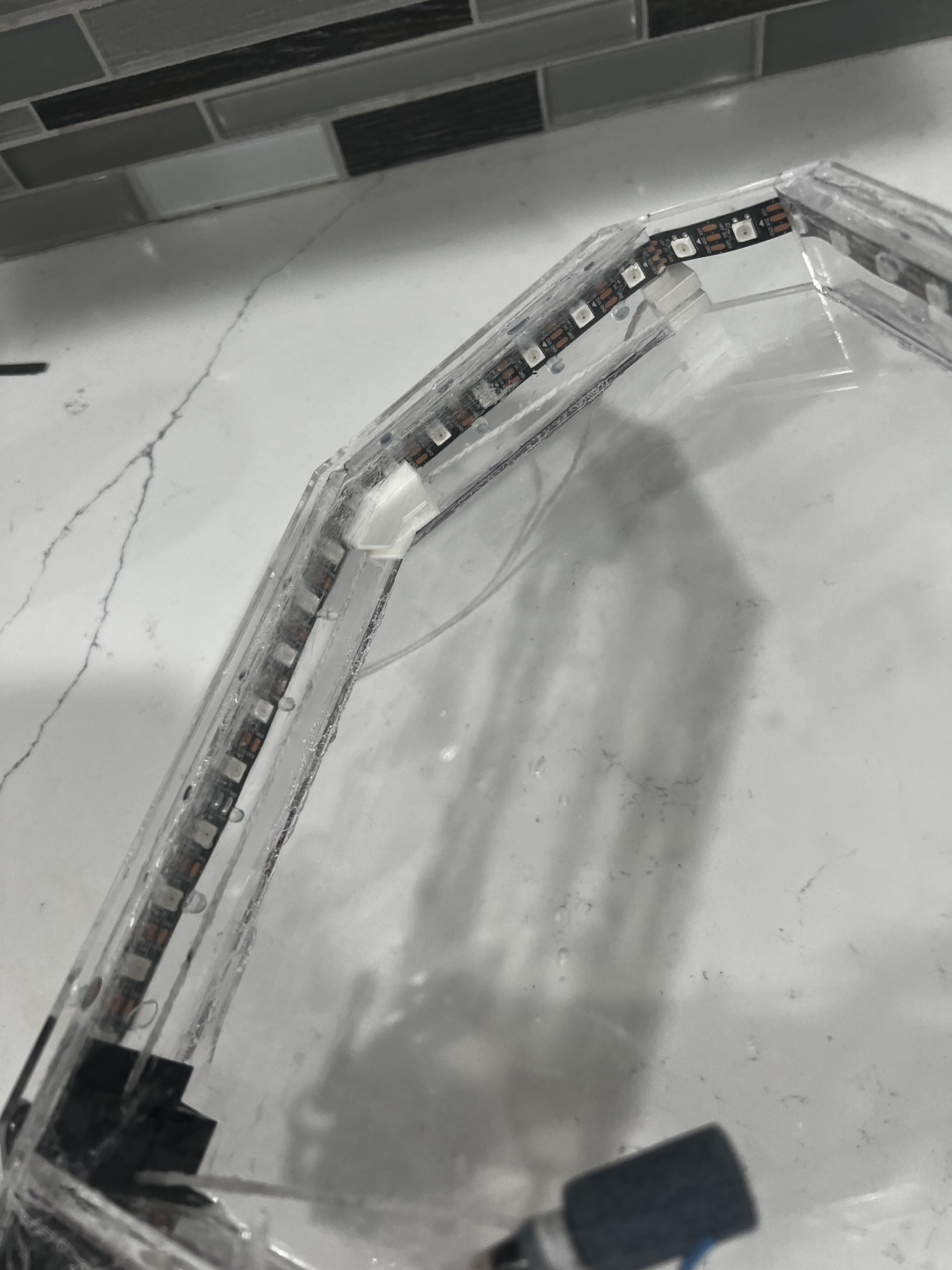
To install the individually addressable LED strip, follow these steps:
- Cut the LED strip to the necessary length to wrap around the container using a sharp cutting tool.
- Stick the LED strip onto the side of the acrylic frame. You can use hot cement to attach the strip to the frame.
Once you have securely mounted the LED strip, connect it to a power source and test the lights.
Connect the ESP8266 Module + WLED Setup
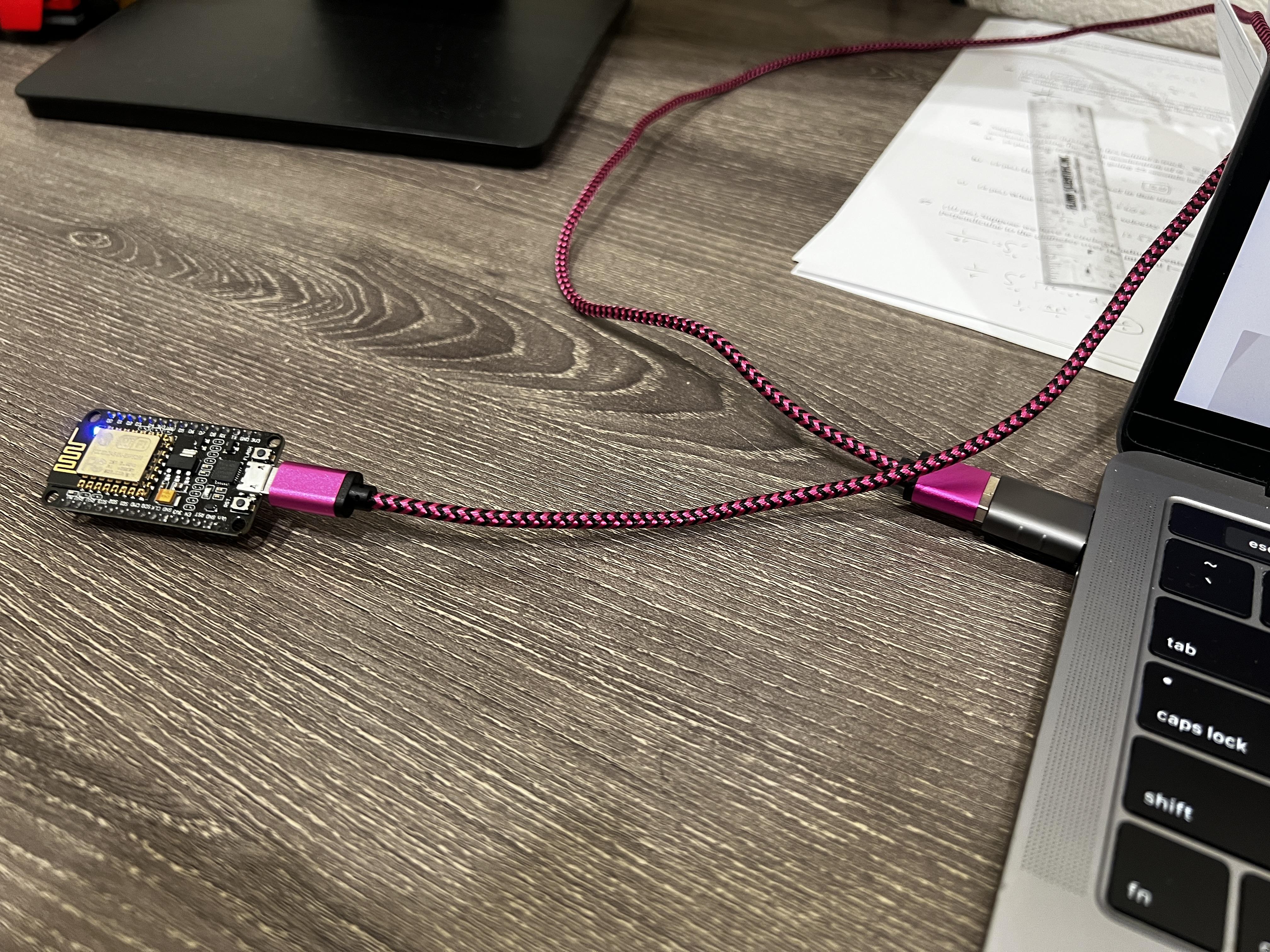
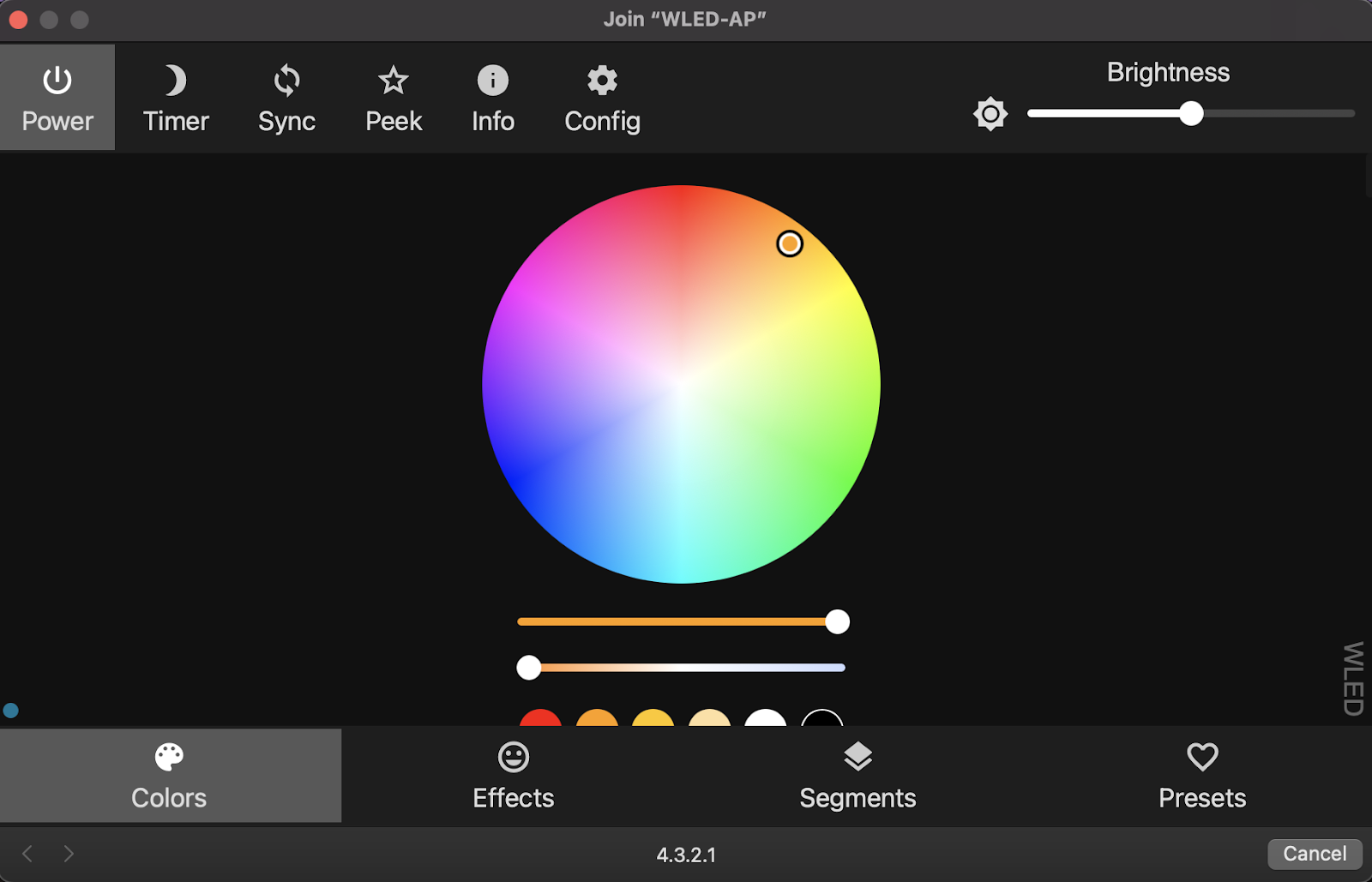
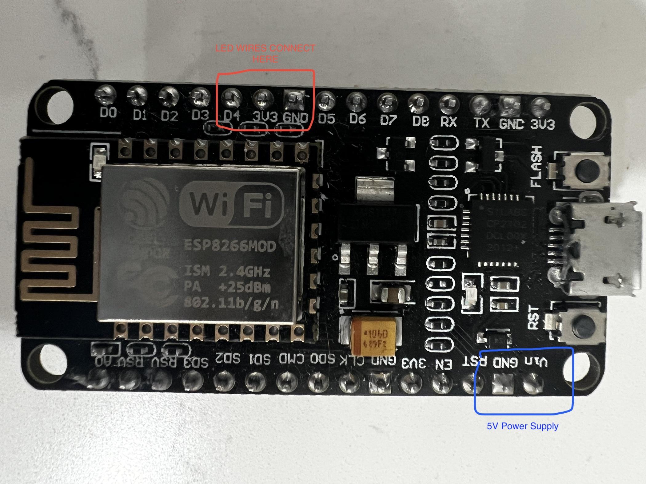
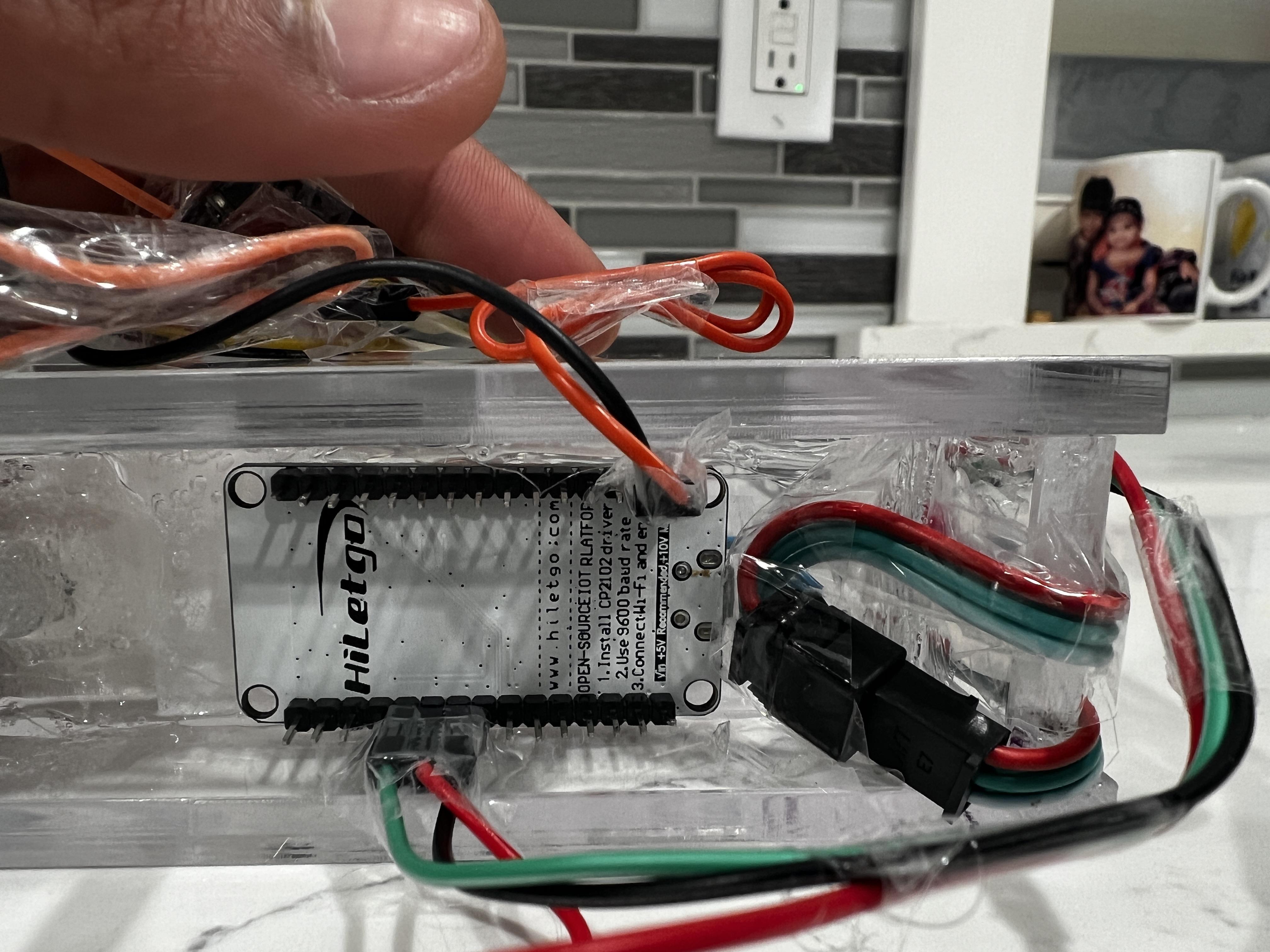
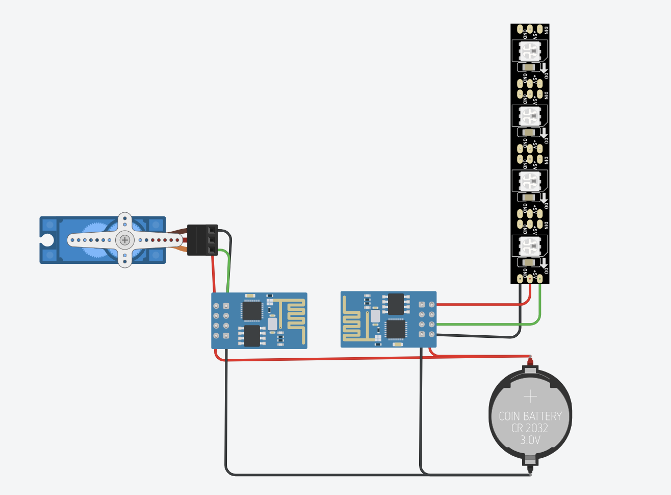
To set up your LED strip with WiFi connectivity, follow these steps:
- Begin by acquiring an ESP8266 module that emits WiFi signals and connect it to a computer using a microusb data cable.
- make sure that your microusb cable can transmit data
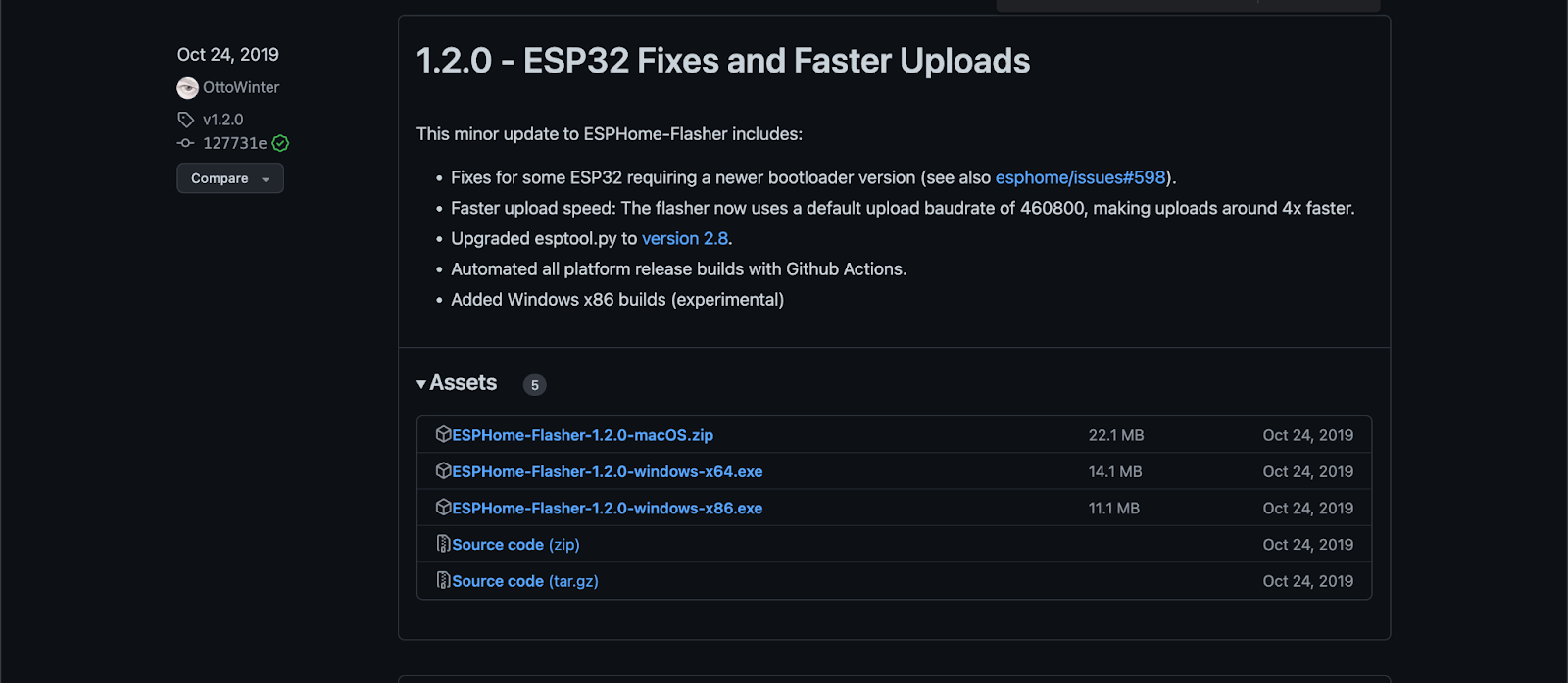
- Download the "1.2.0 - ESP32 Home Flasher" application from Github
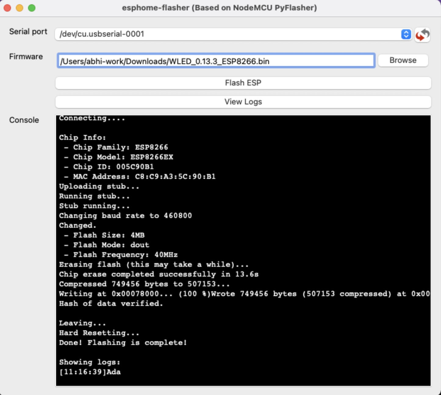
- Open the application and click on "Flash ESP"
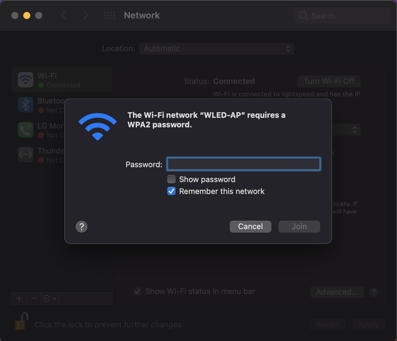
- After flashing is complete, a new Wifi connection will be available and you should connect to "WLED-AP"
- default password = wled1234
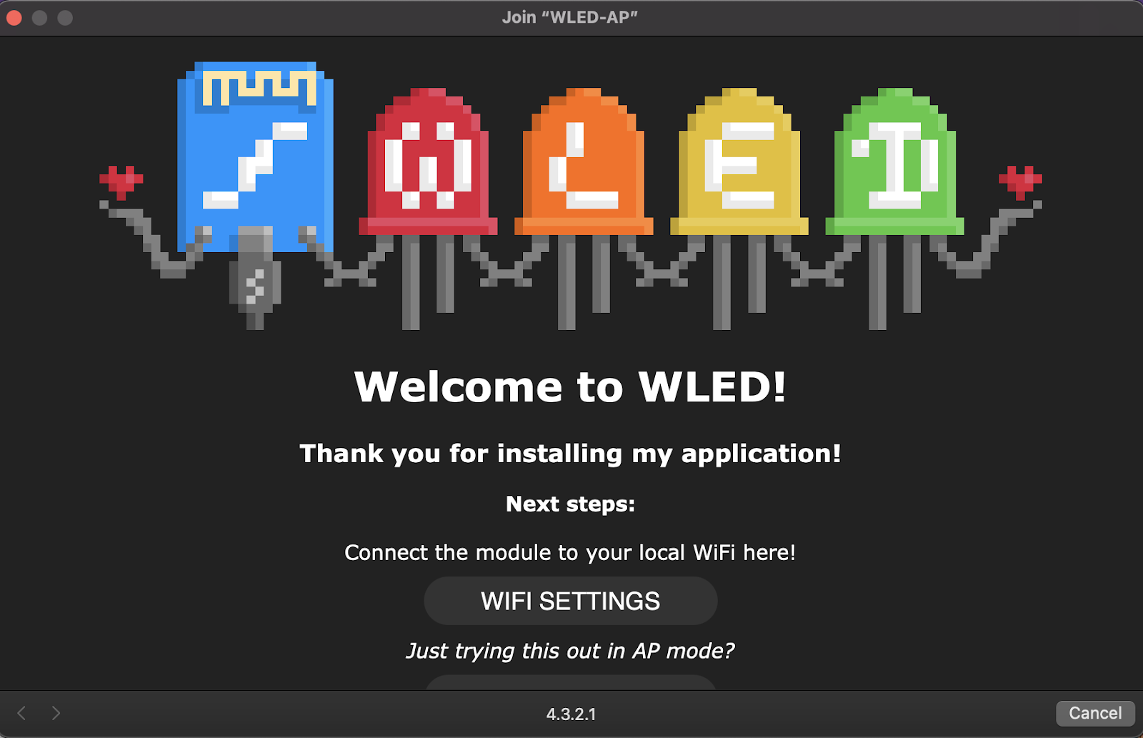
- Once connected, click on WiFi settings if you want to do some customization.
- After you are done, a screen shown on Figure 7 should be available for you to play around with the light settings
- Use a suitable cement type to fix the ESP module onto the bottom of the acrylic frame, as shown in Figure 08.
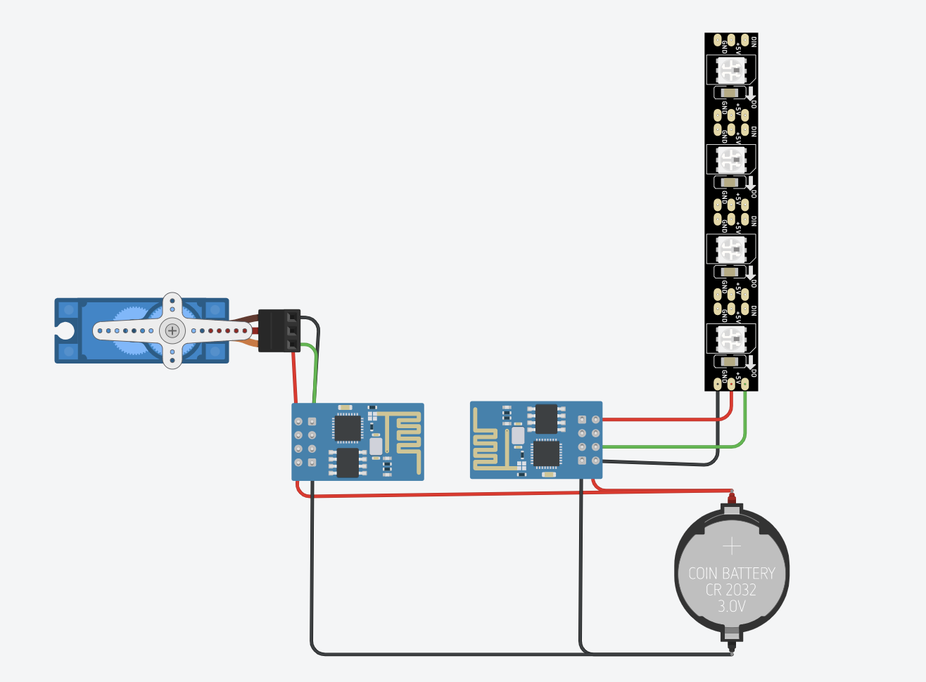
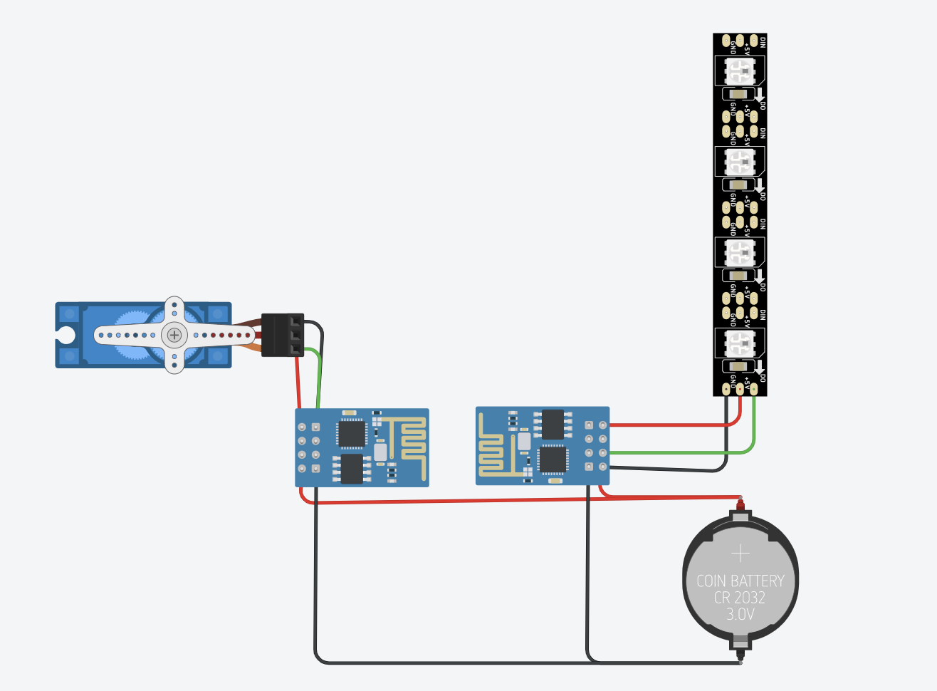
- Connect all the wires from the LEDs to the ESP8266 module to establish connectivity:
- Data, green wire connects to D4
- Positive, red wire connects to 3v3
- Negative, white wire connects to GND
- (The last image has the circuit diagram for reference)
By completing these steps, your LED strip should now be ready to receive WiFi signals and can be controlled via your smartphone or other connected devices.
Attach Servo Motor
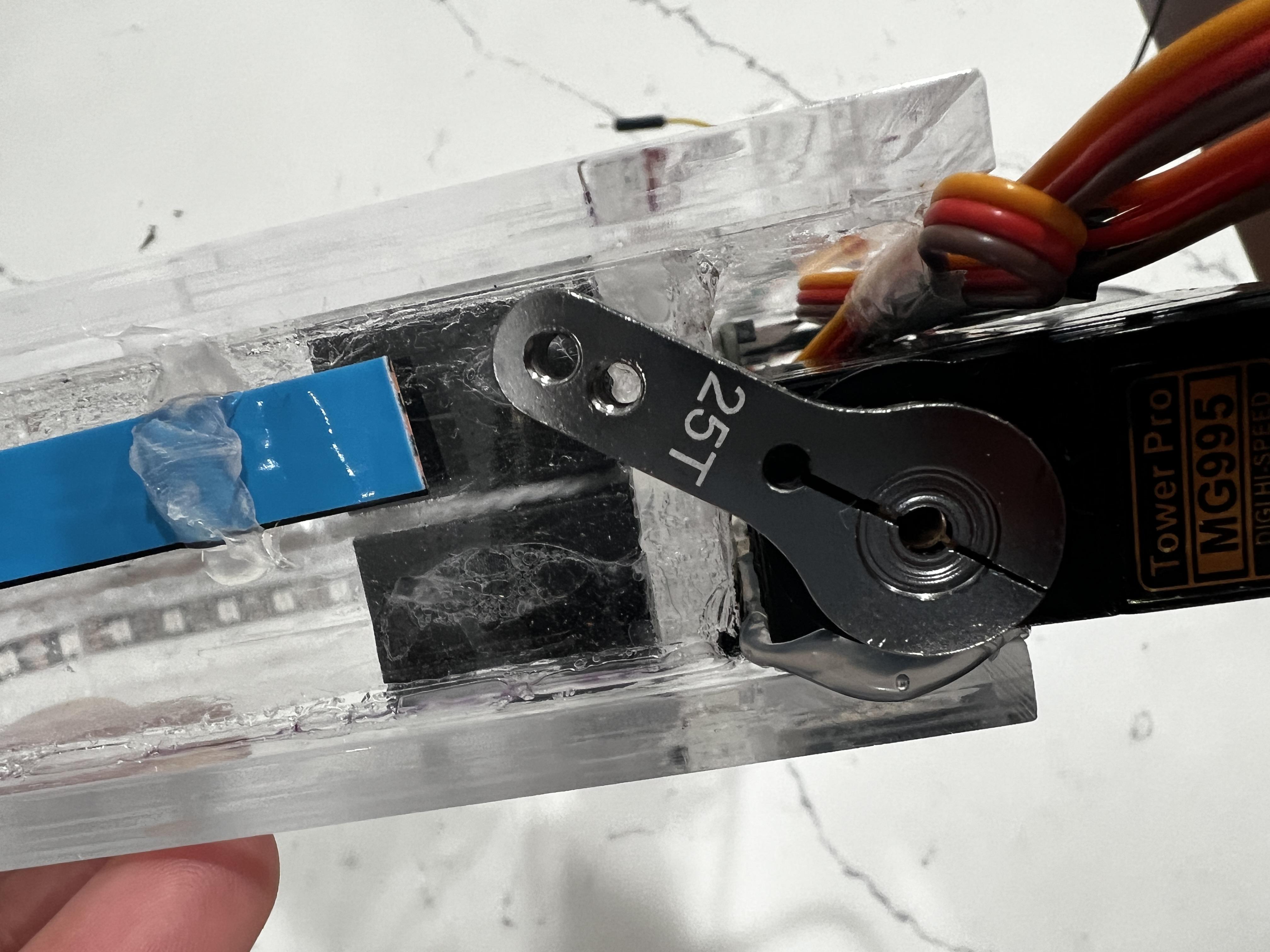
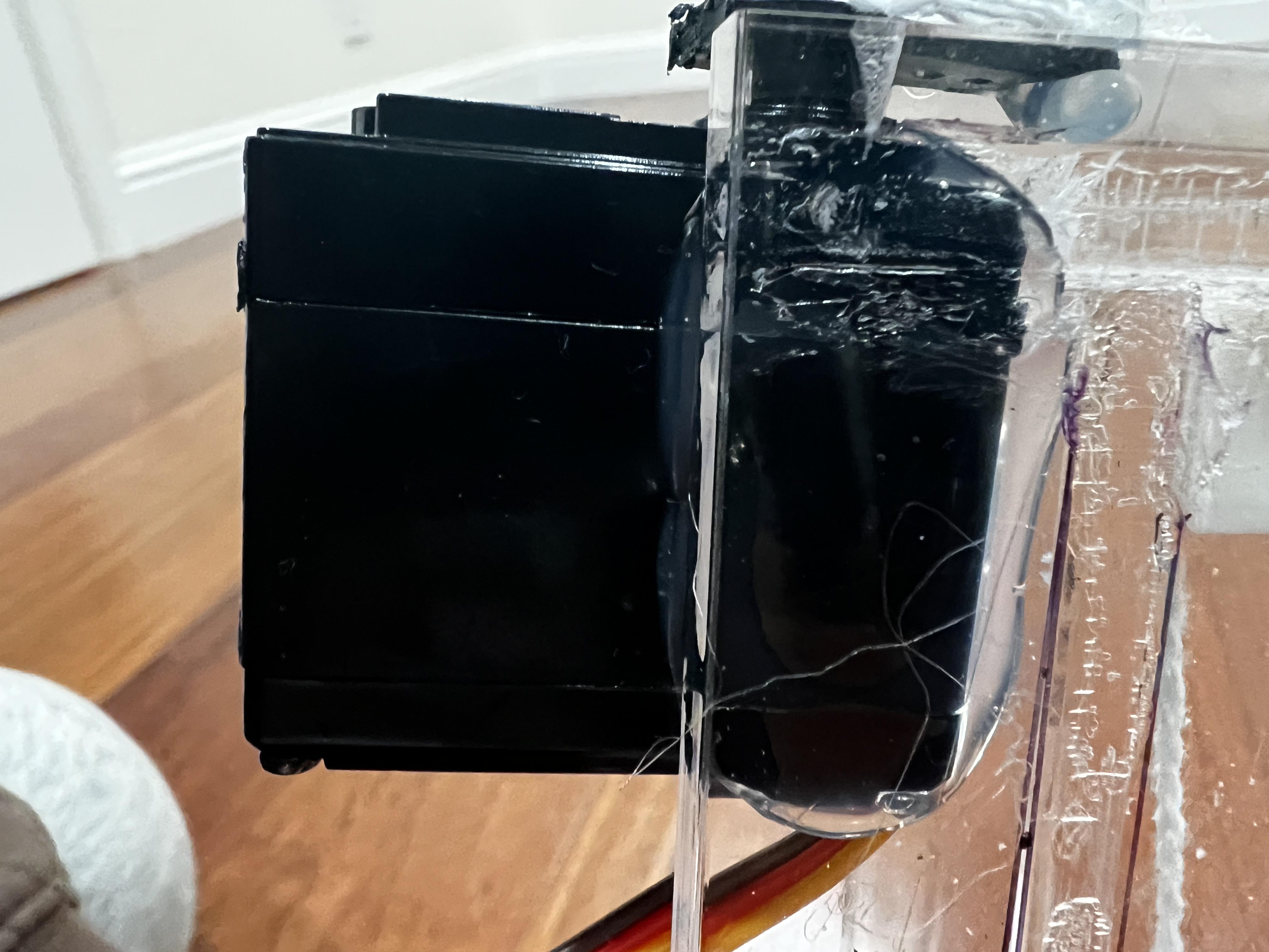
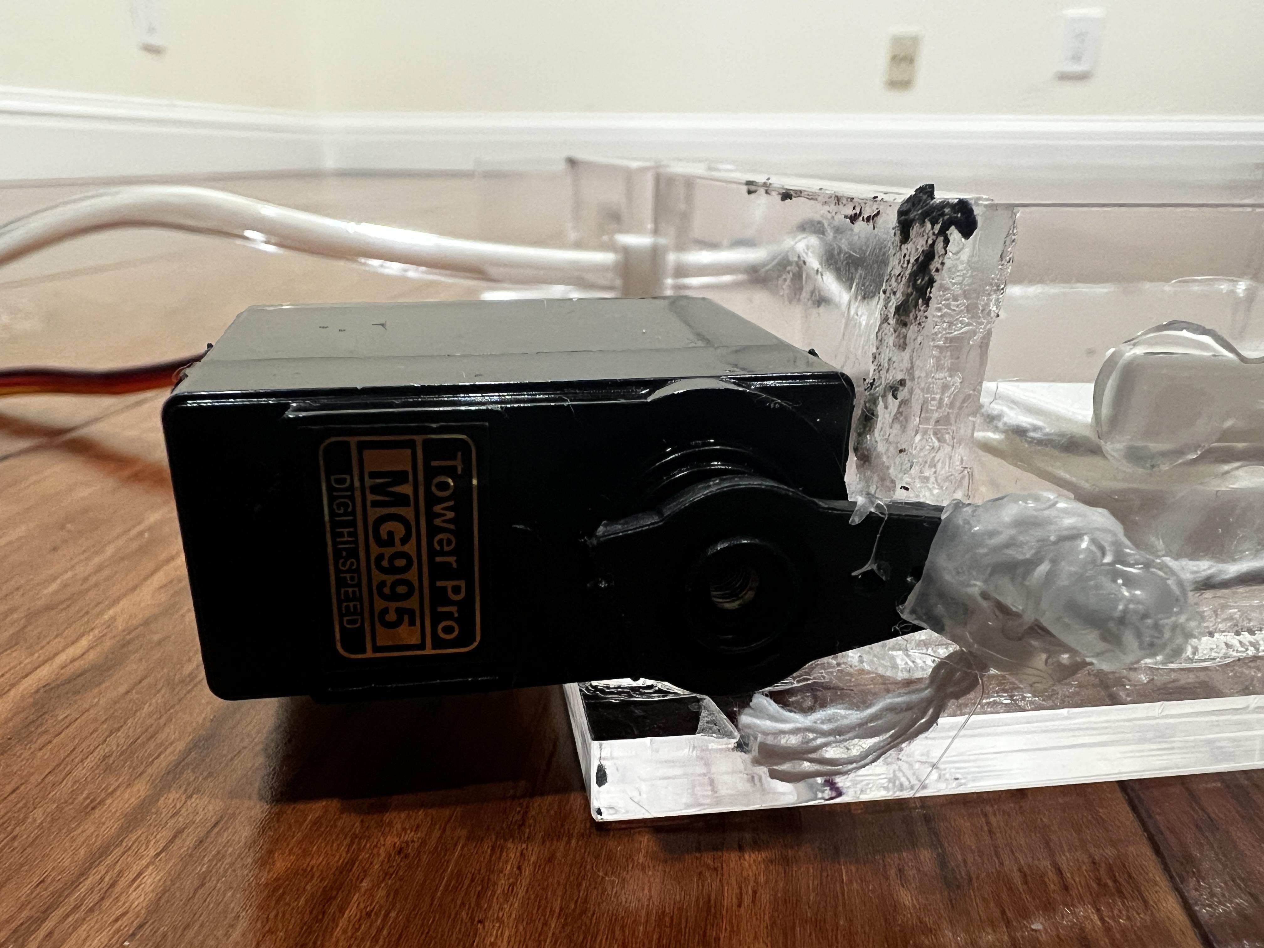
- Begin by attaching the aluminum adjustable servo horn to the MG995 servo motor
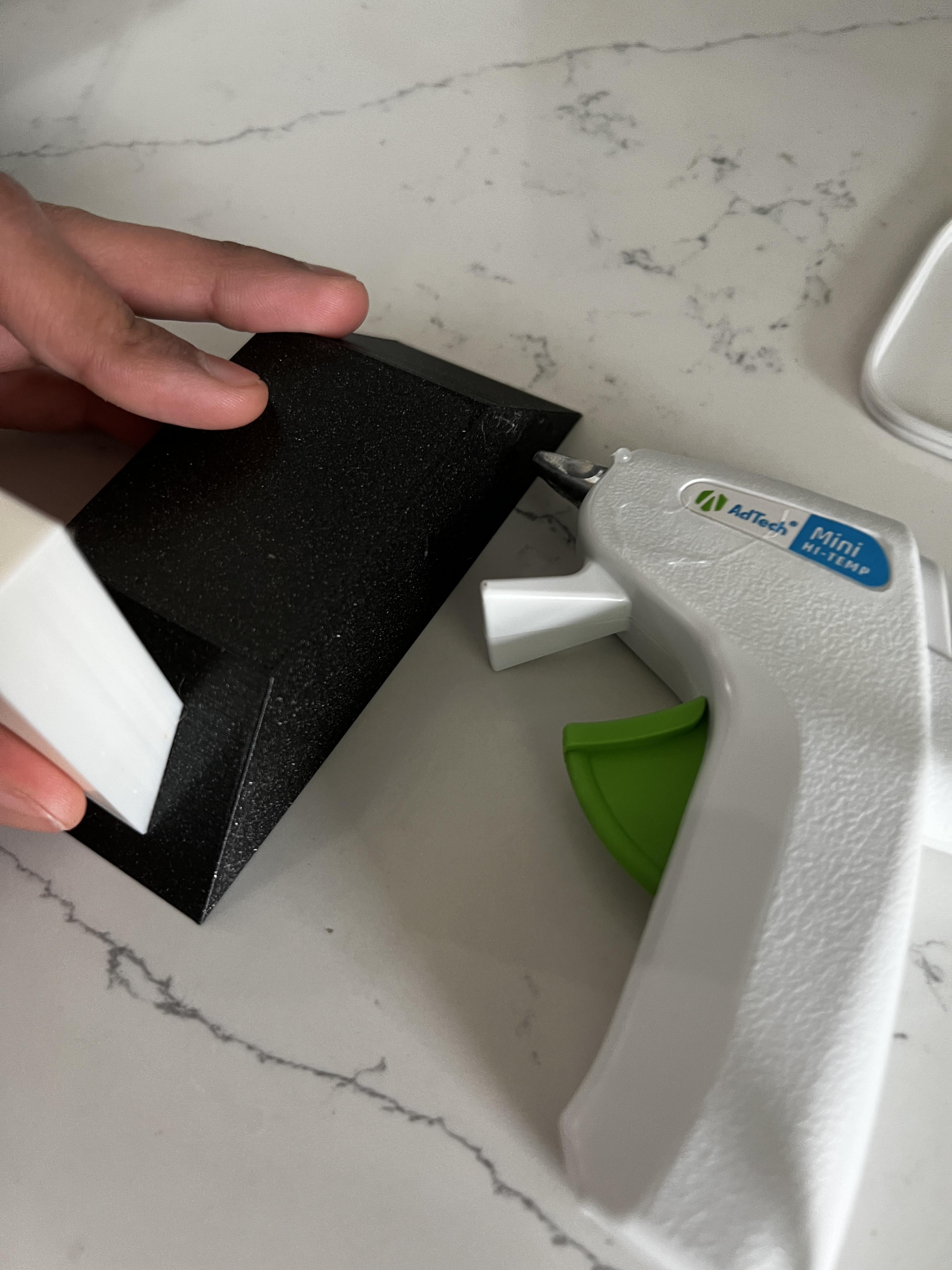
- Fix the servo motor to the acrylic frame using hot glue, as shown in Figure 02 and 03 (glue it to the side with the string coming down).
- Move the servo horn so it is pointing straight up
- Then, tie the string to the top hole of the servo horn and hot glue it
Connect Microcontroller to Servo
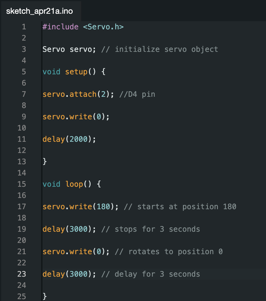
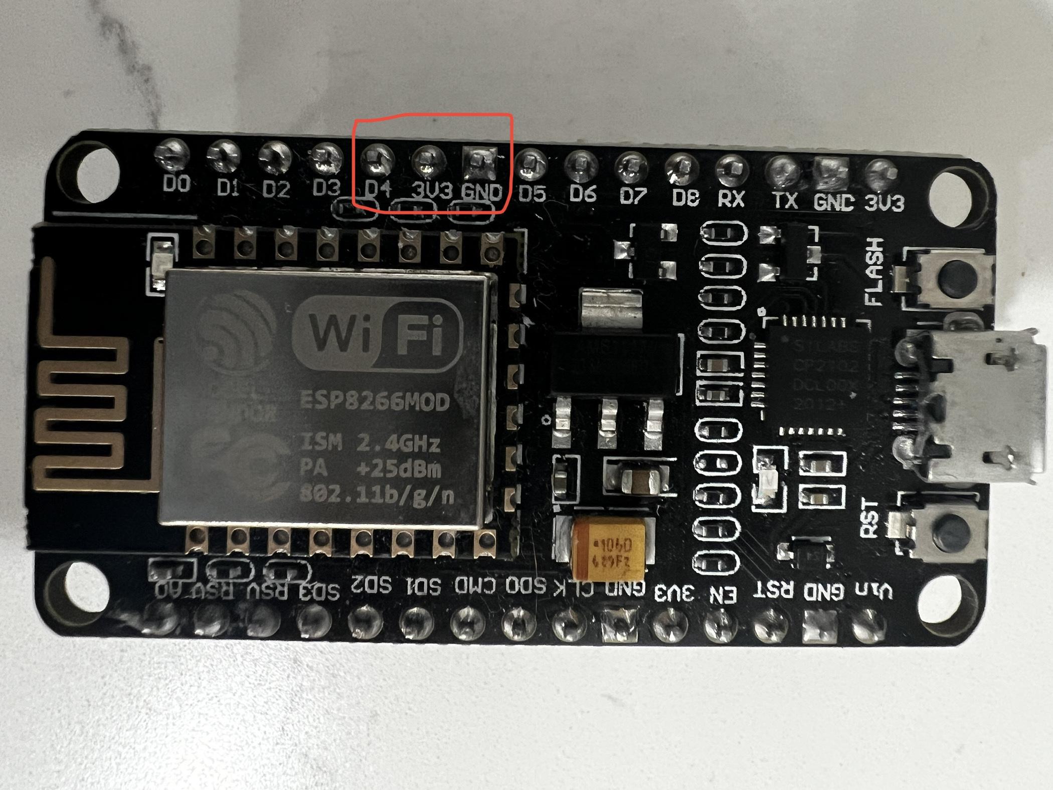
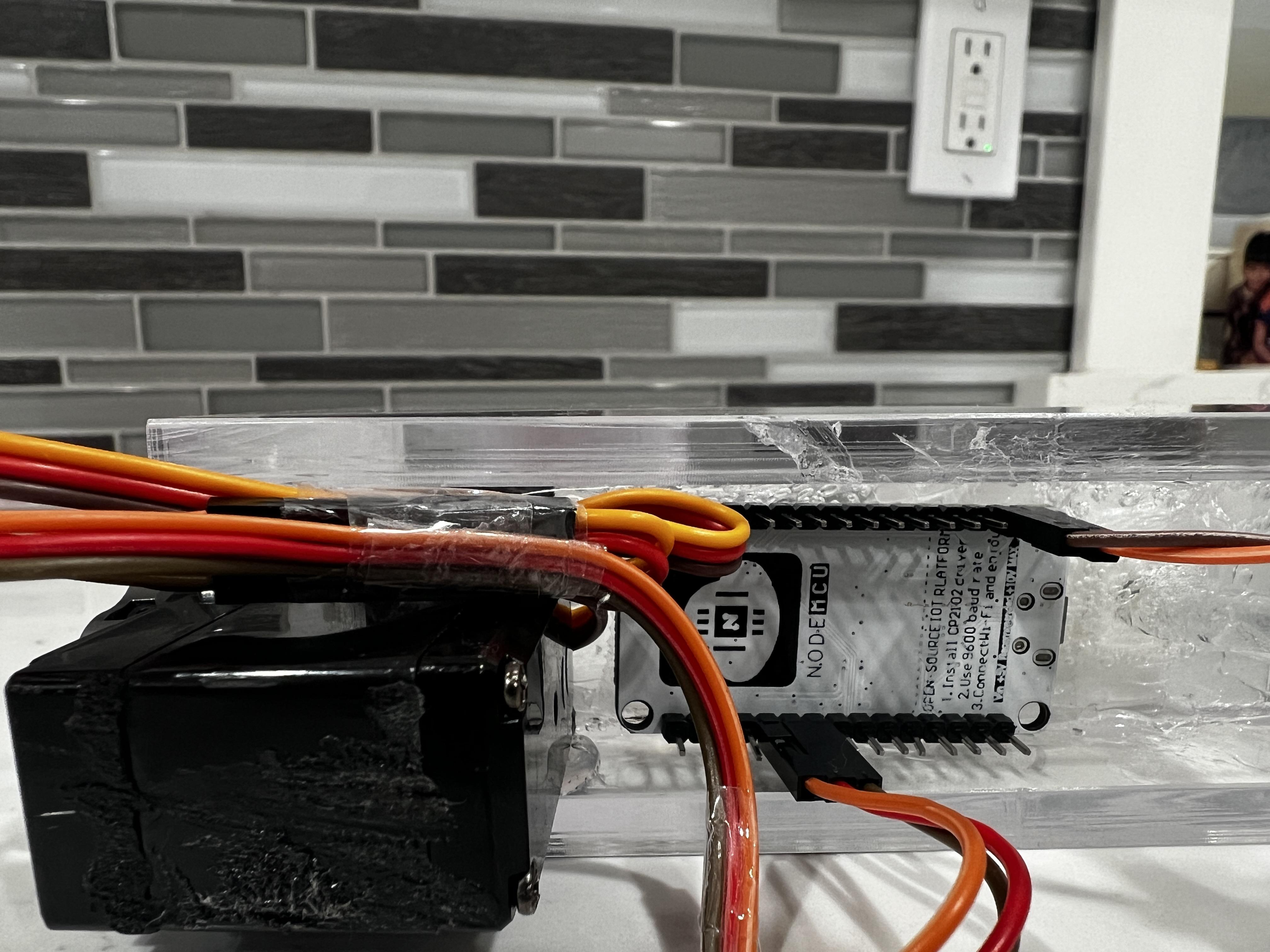
To set up any microcontroller to control the servo (I used another ESP82666), follow these steps:
- Begin by downloading the Arduino IDE
- Acquire any microcontroller and upload the code provided above to the board.
- Make the circuit using the instructions shown in Figure 02 and 03.
- If you are using another Node MCU ESP82666 for the servo connect the wires as such:
- Data, orange wire connects to D4
- Positive, red wire connects to 3v3
- Negative, brown wire connects to GND
- (The last image has the circuit diagram for reference)
- Next, use hot glue to fix the microcontroller onto the acrylic frame.
Box for Wiring

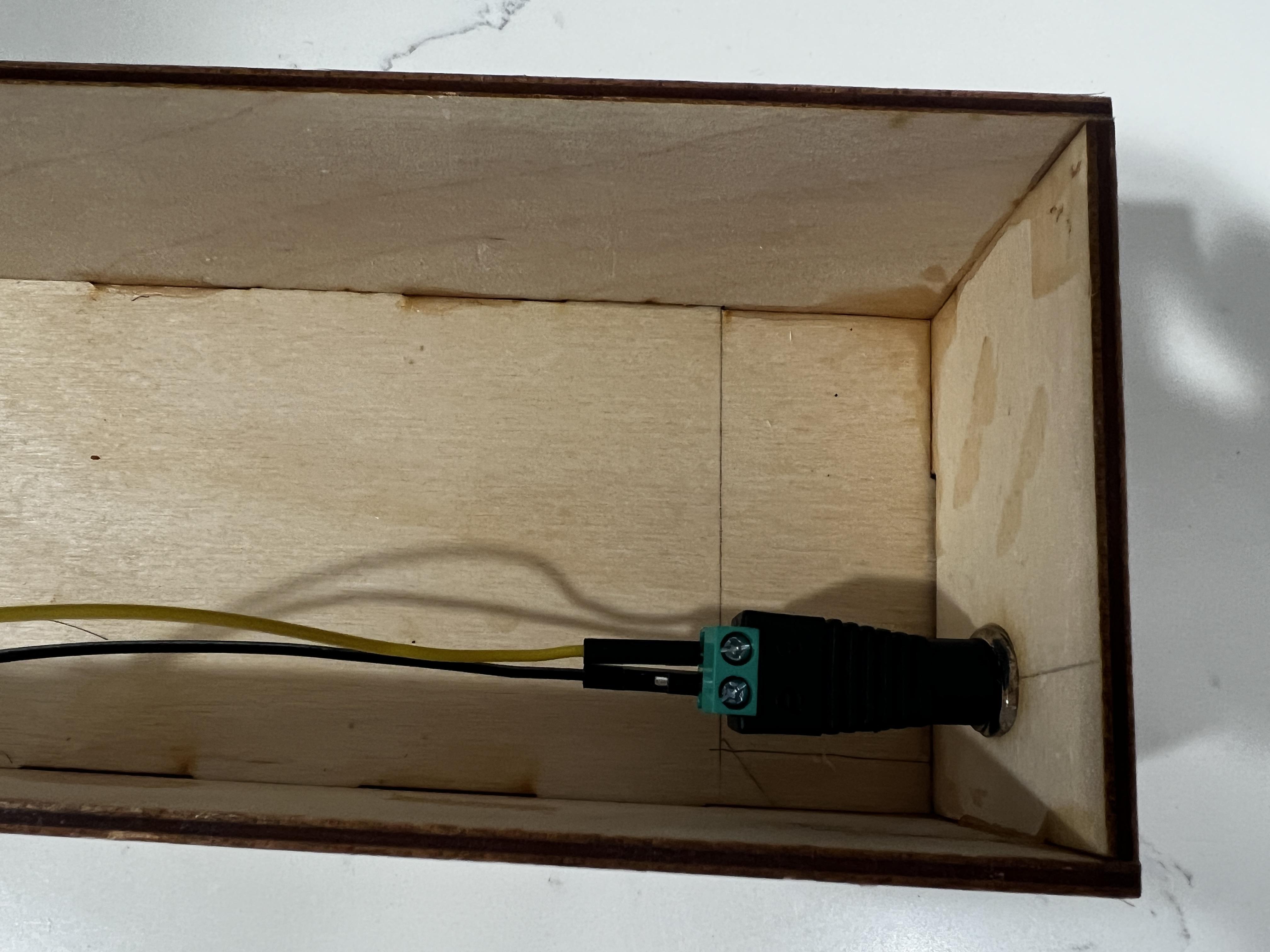
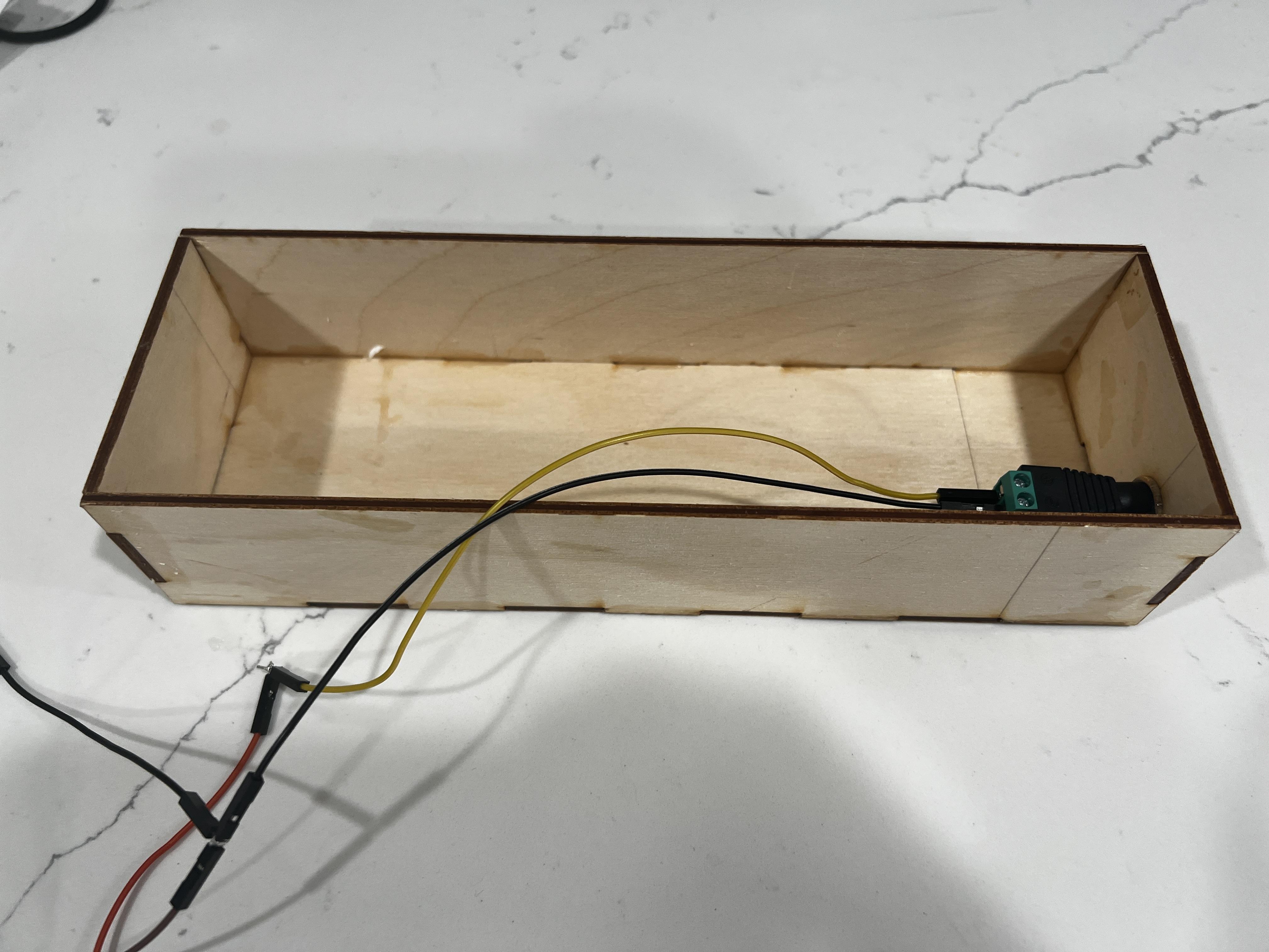
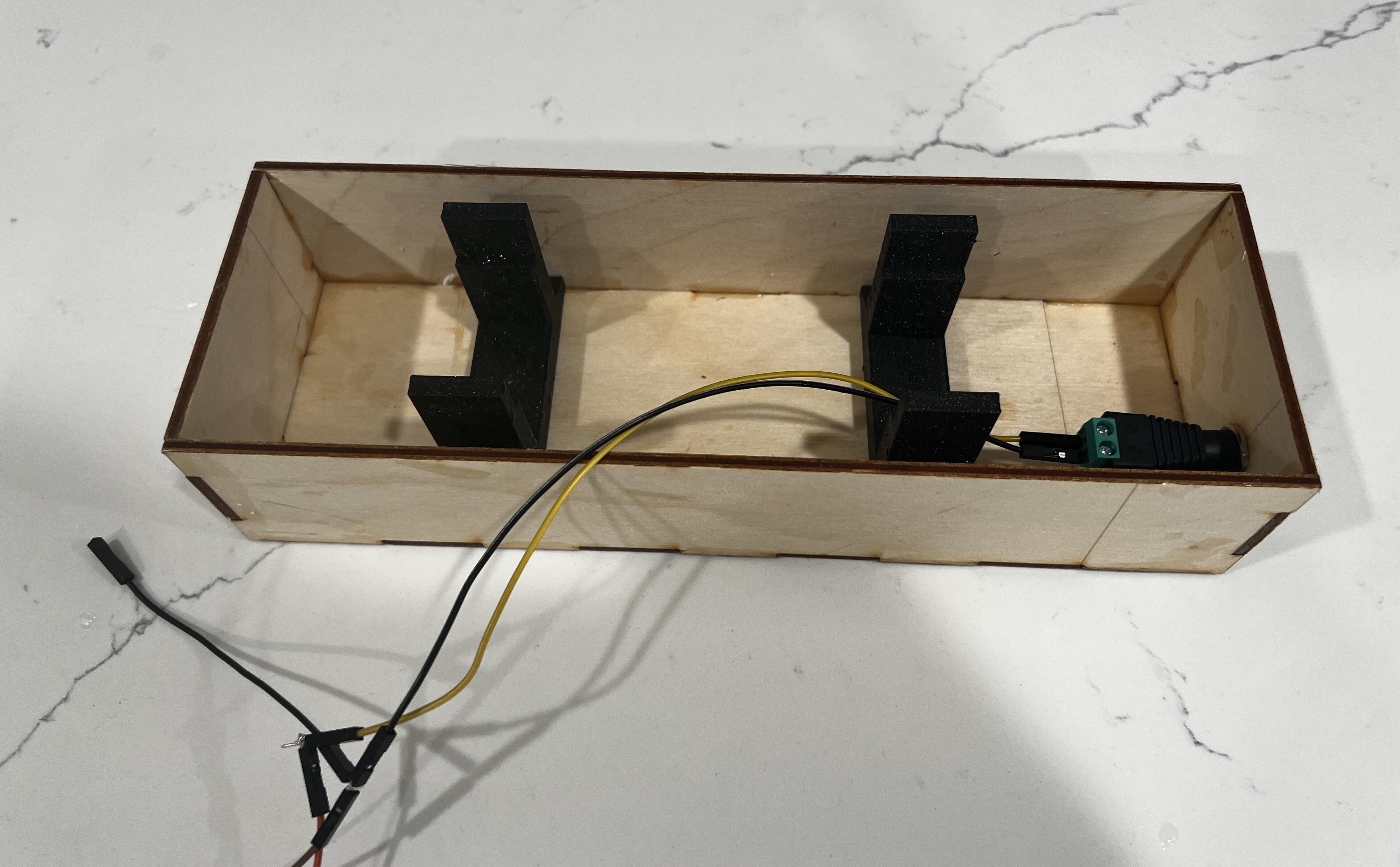
To complete the construction of the box for wiring, follow these steps:
- Laser cut a wood box using the illustrator file attached below
- Assemble the box and hot glue a barrel connector to the side, as shown in Figures 01 and 02.
- Next, attach a positive and a negative wire that will be used to power the microcontrollers
- Hot glue the WL010 (stands) to the bottom of the box
Downloads
Final Steps
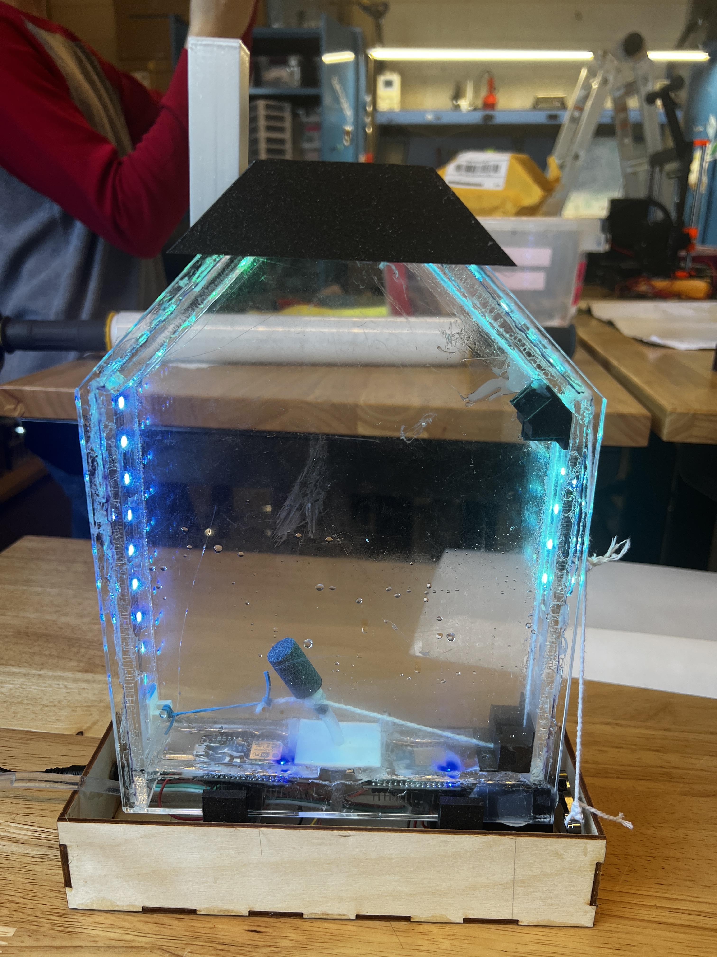
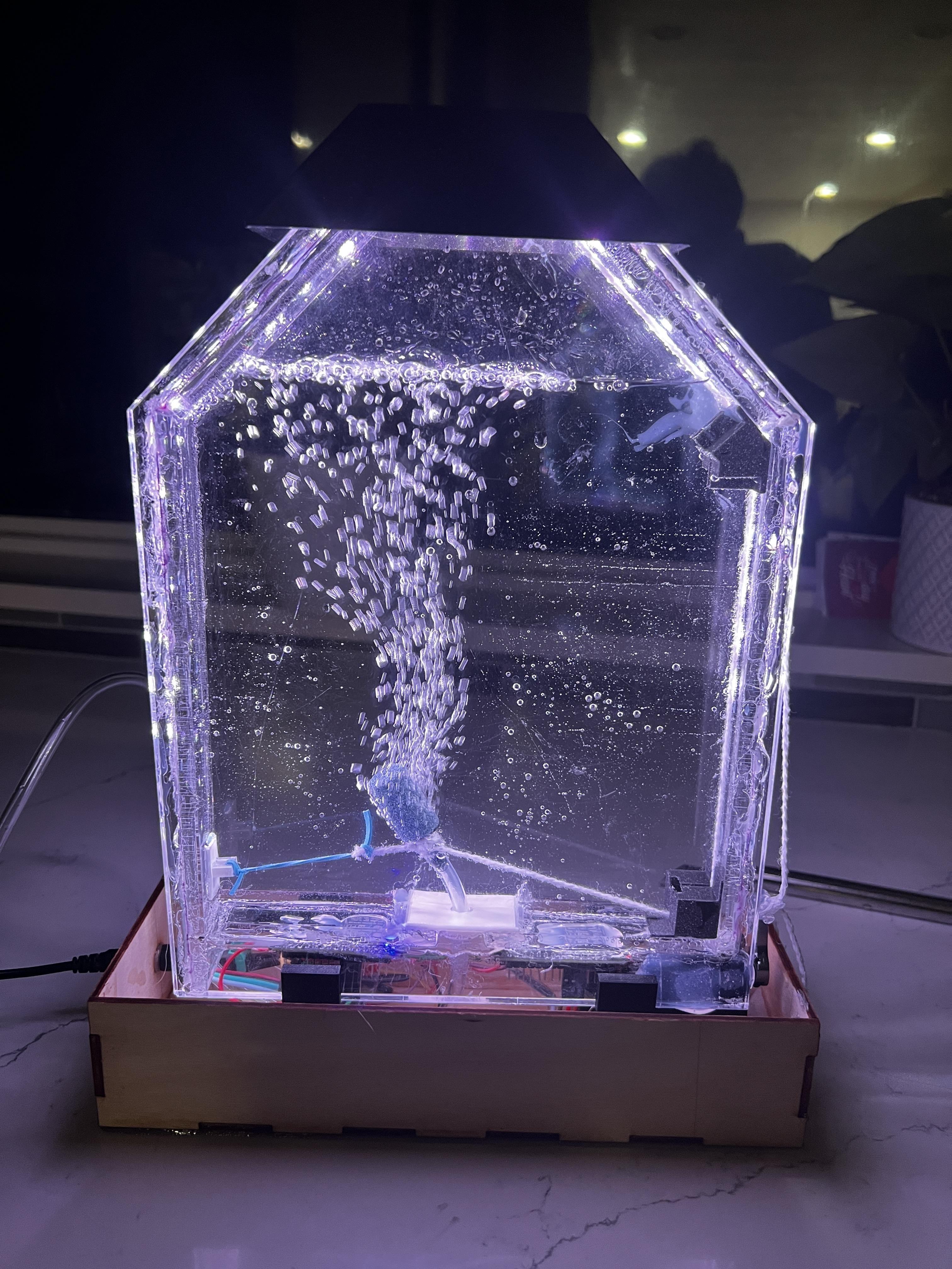
From the box, provide power to both microcontrollers, your LEDs should light up and the servo should be able to move the air bubble release stone back and forth.
(See tinkercad circuit above if you are still confused on how to wire up everything)
Final Steps:
- Add water to the container
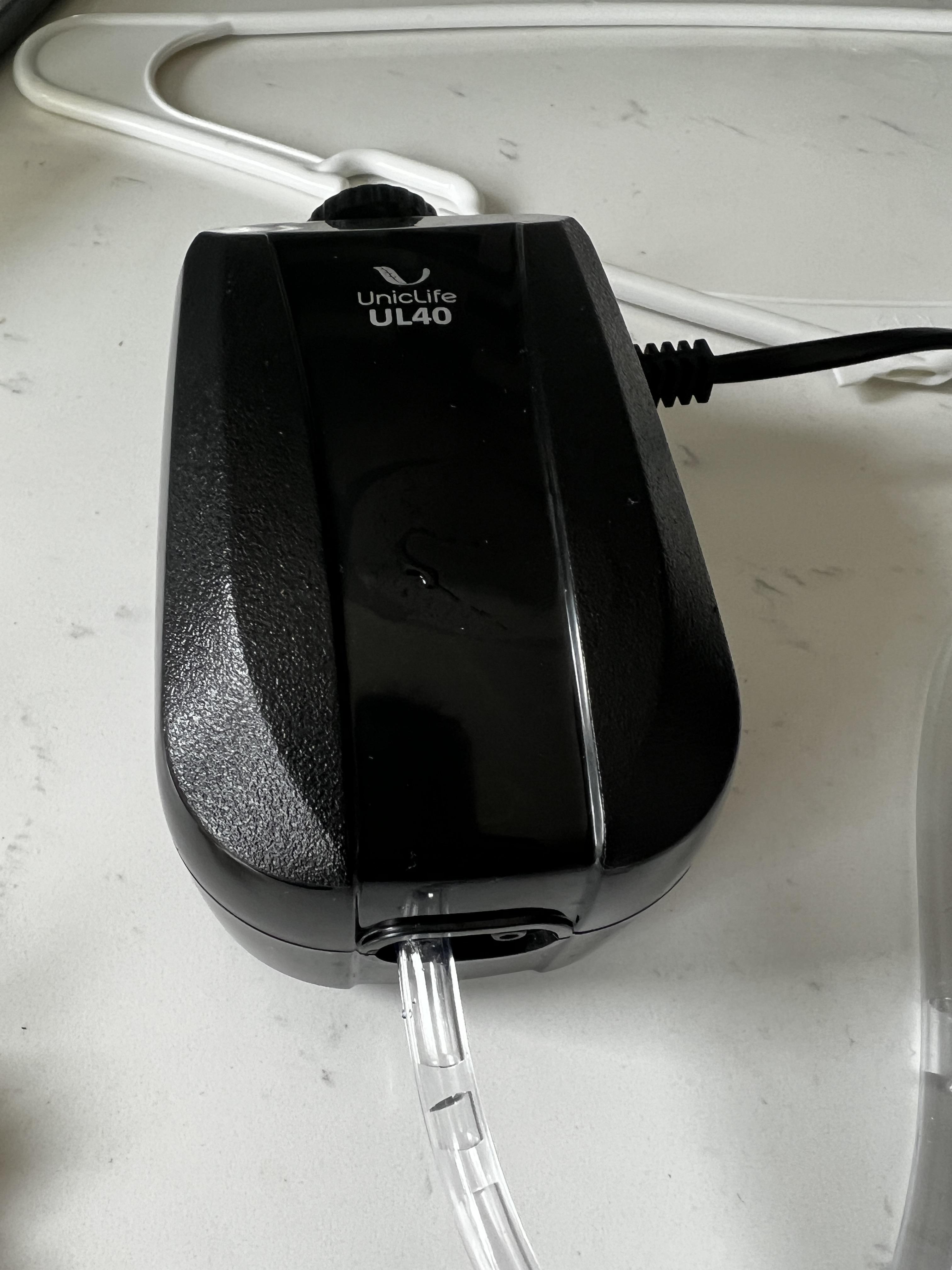
- Connect air pipe to an air pump
- Add the 3d printed roof and chimney on top
By following these instructions, you should be able to successfully complete the construction of the water lamp.