Smart Room With Raspberry Pi : 8 Steps - Instructables
by Lars Soens in Circuits > Raspberry Pi
708 Views, 0 Favorites, 0 Comments
Smart Room With Raspberry Pi : 8 Steps - Instructables

Hello everyone, for my school project ‘Project One’ at MCT Howest Kortrijk, we had to make an IoT-device with at least 3 sensors and at least one actuator. My idea was to make a Smart Room who gives you realtime data of the room. I thought it was a good idea because I am also very much in my room and I often forget to ventilate the room. The whole project runs on my Raspberry Pi 4 (Frontend, Backend, Database, Webserver…). If you want to recreate my project, you can follow the steps below. Good luck!
Supplies
- Raspberry Pi 4 2GB Ram
- Raspberry Pi USB-C Adaptor
- Micro SD 16GB
- Breadboard 3.3-5V Power Supply
- Breadboard (2)
- DC Motor
- LDR Sensor
- One-Wire Temperature Sensor
- MQ-135 Air Quality Sensor
- White Leds (4)
- RGB Led
- LCD-display
- MCP3008
- AC/DC Convertor
- Male-Male Cables
- Male-Female Cables
- Female-Female Cables
- Set of Resistors
You can find more info about the supplies in my BOM (bill of materials) document.
Downloads
Circuit + Breadboard Scheme
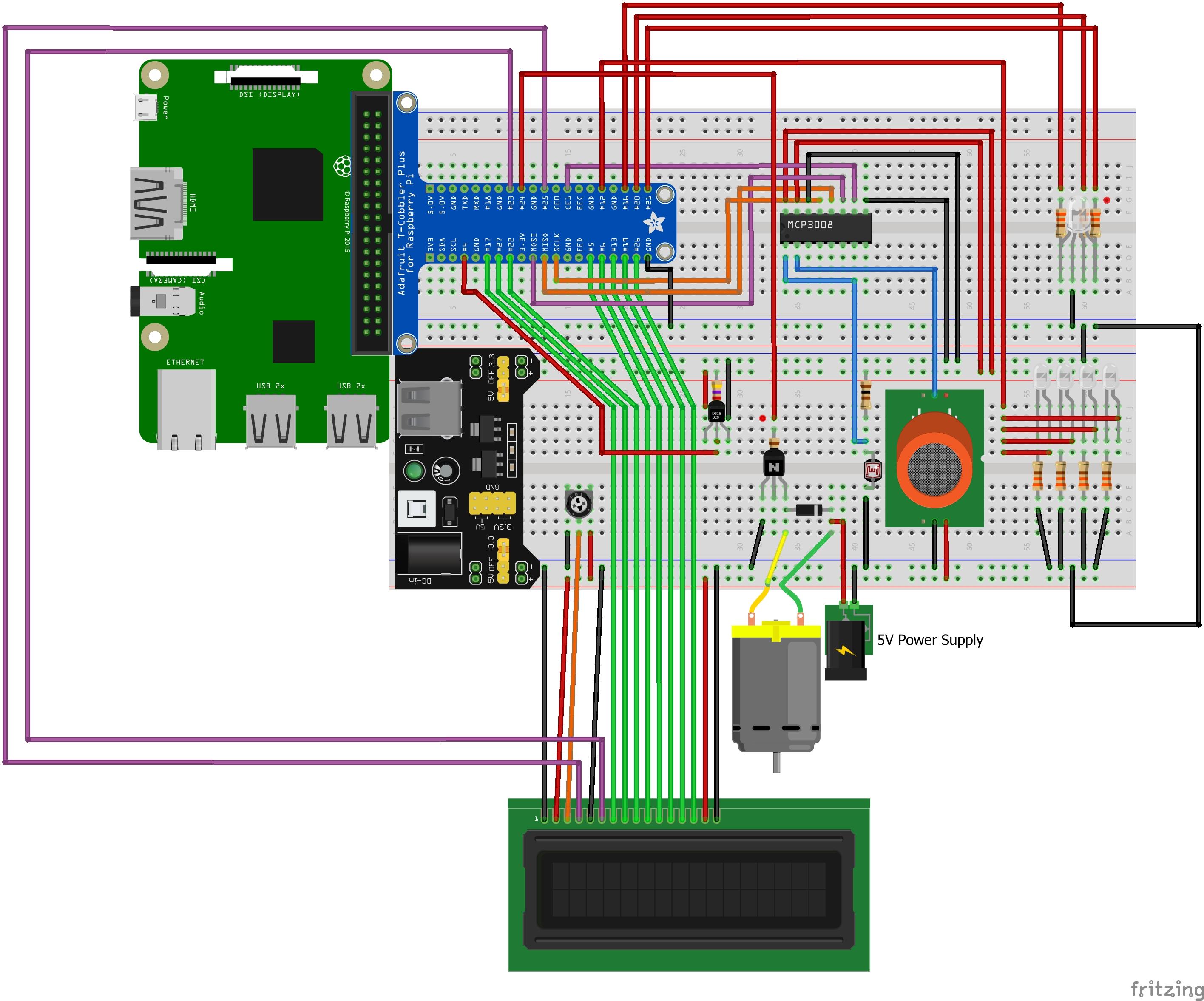
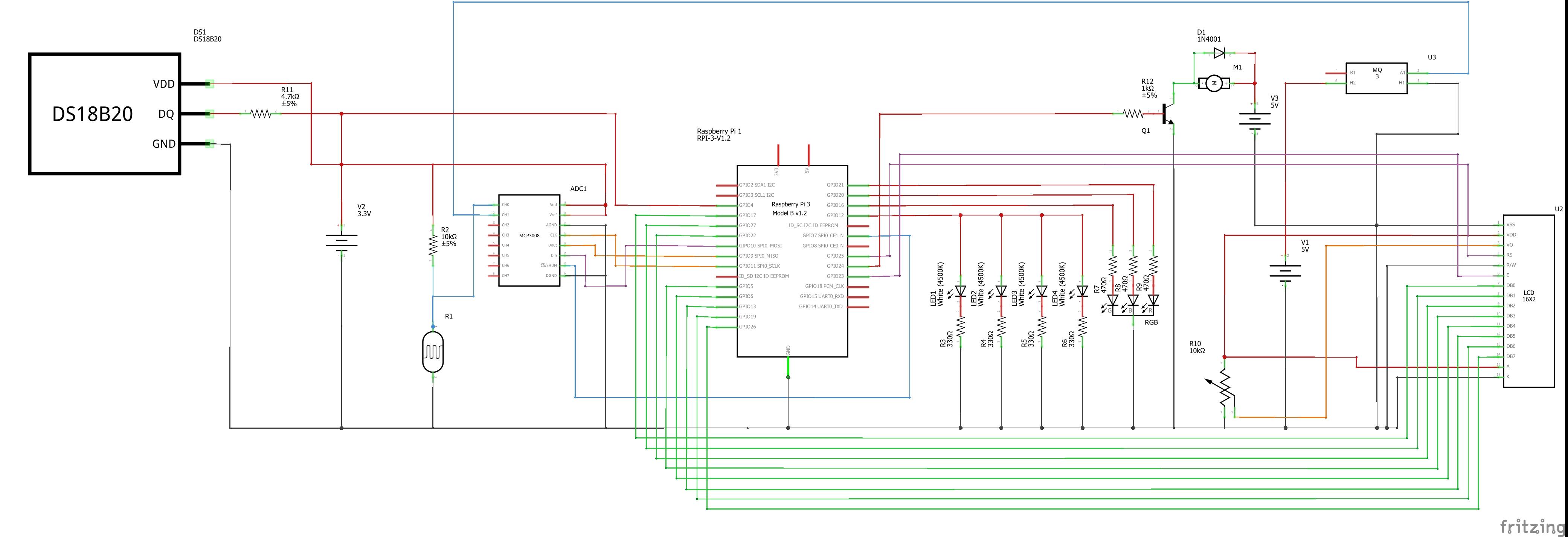
For making the circuit and the breadboard scheme, I used the program Fritzing. It's an easy way to represent graphically the electrical circuit.
If you recreate the circuit, make sure everything is connected correctly. It's very important to not damage the hardware.
Creating the Database
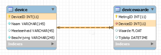
To store the data that will be created, I had to design a database model (3NF). I decided to design a simple database with two tabels. One table is called 'device', in this table you have all the sensors & actuators with their own ID, name, measuring unit and a description. The other table is called 'devicewaarde', this table is linked to the first table. This is the table where the data will be stored. Here we have all the measurements with their own ID, the device ID and also the time of when the data was sent to the database. Because the two tables are linked, you can make a join in SQL to bring them together.
Up here, you can see the ERD (Entity Relationship Diagram) that I made.
You can find my database export on my Github.
Setting Up the Raspberry Pi
Now we can start setting up our Raspberry Pi.
Part 0: Downloading software
1) The first thing we need to do is download the right image. You can download it here.
After that you downloaded the image, you need to unzip it, this may take a while.
2) We will need Win32DiskImager to write the image to the Pi.
You can download the software here.
3) We also need Putty to connect our PC to our Pi.
You can download it here.
Part 1: Configuring the SD Card
When everything is downloaded, we can start setting up the SD Card.
1) Format the SD Card completely.
2) Open Win32DiskImager, select the right file and directory and click on write. This may also take a while.
3) Now need to edit the 'cmdline.txt' on the SD Card, add 'ip=192.168.168.168' at the end of the file and save it.
4) Add a new file 'ssh'. (Make sure the file has no extension)
5) Remove the SD Card safely and plug it into your Raspberry Pi.
6) Take a LAN cable and plug it into your Pi and into your PC.
Part 2: Setting up the Pi
1) Make sure that the IP-address of your wired interface from your PC is set up static at '192.168.168.100'.
2) Open Putty and type the IP '162.168.168.168' and Port '22' and connection type: SSH.
3) The login is 'pi' and the password is 'raspberry'.
4) Login as root:
sudo -i
5) Enable interfaces in raspi-config
raspi-config
Enable the following interfaces:
- SPI
- One-Wire
6) Expand the file system in raspi-config
Go to 'Advanced' and select 'Expand'
7) Add your home wifi-network. Replace 'ssid' by your own networkname and 'password' by your own password.
wpa_passphrase 'ssid' 'password' >> /etc/wpa_supplicant/wpa_supplicant.conf
8) Make connection on your wifi-network.
wpa_cli
interface wlan0
reconfigure
list_networks
Now you can see on which network the Pi is connected.
You can double check the connection by requesting the IP.
ip a
Part 3: Update the Raspberry Pi and install the Apache webserver
1) We need to make sure that all the software on the Pi is the latest version available. We can do it in the following way.
sudo apt update
sudo apt upgrade
This may take a while.
2) Install the Apache webserver
apt install apache2 -y
3) Install MariaDB
apt install mariadb-server mariadb-client -y
Part 4: Make Python ready
Before we can make Python ready, you have to make connection with Visual Studio Code via SSH.
1) Install the correct Python packages
pip3 install flask-cors
pip3 install flask-socketio
pip3 install mysql-connector-python
pip3 install gevent
pip3 install gevent-websocket
Part 5: Reboot the Pi
The last step we need to do is rebooting the Pi. You can do it like the following way
sudo reboot
Setting Up the Database on the Raspberry Pi Via SSH
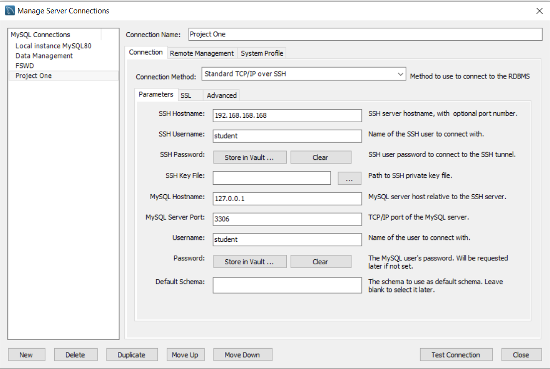
The setup of the Pi is already done, but there is one important step left before we can start programming. We have already designed the database, now we have to connect it to the Raspberry Pi.
To set up the database, we need to connect our Pi with MySql. The easiest way is to make a new connection in MySQL Workbench. We will use a TCP/IP over SSH connection. Here above you can see the settings that I use to set up the connection.
Backend Code (Python)
The setup is done now, we can start coding!
To write the code, I use the program Visual Studio Code with a SSH extension. This extension is important because we need to program on the Pi over a SSH connection, so we also need a LAN cable.
The whole backend is written in the language Python combined with Flask. The backend is very important to send data to the frontend. In the backend I used routes*, socket.io* and threading*.
1. Routes
I used routes to get data out of the Datarepository, where all the Sql queries are written. With the routes you can send data from the database to the frontend.
2. Socket.IO
I used socket to send realtime data from the backend to the frontend and vice versa.
3. Threading
I used threading to run different tasks at the same time.
You can find my backend code on my GitHub.
Frontend Code (HTML, CSS, Javascript)

When all the code of the backend is written, we can start writing the frontend.
Before we could start coding, we had to make wireframes in Adobe XD. With these wireframes, we have a good reference to start writing HTML & CSS.
For me it was a bit hard to code in HTML and CSS. I like it but it's a bit hard because I had no foreknowledge. I tried my best, and kept the responsive website as simple as possible. I really like coding in Javascript. It's nice that you can do so much with it.
In Javascript I also used the routes that I wrote in the backend and I also used Socket.IO to send data from frontend to backend.
For my HTML-page 'Grafieken', I used the Javascript extension called ApexCharts.js. This is made to show the data in a chart.
You can find my frontend code on my GitHub.
Building the Case
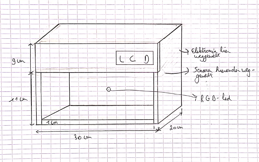
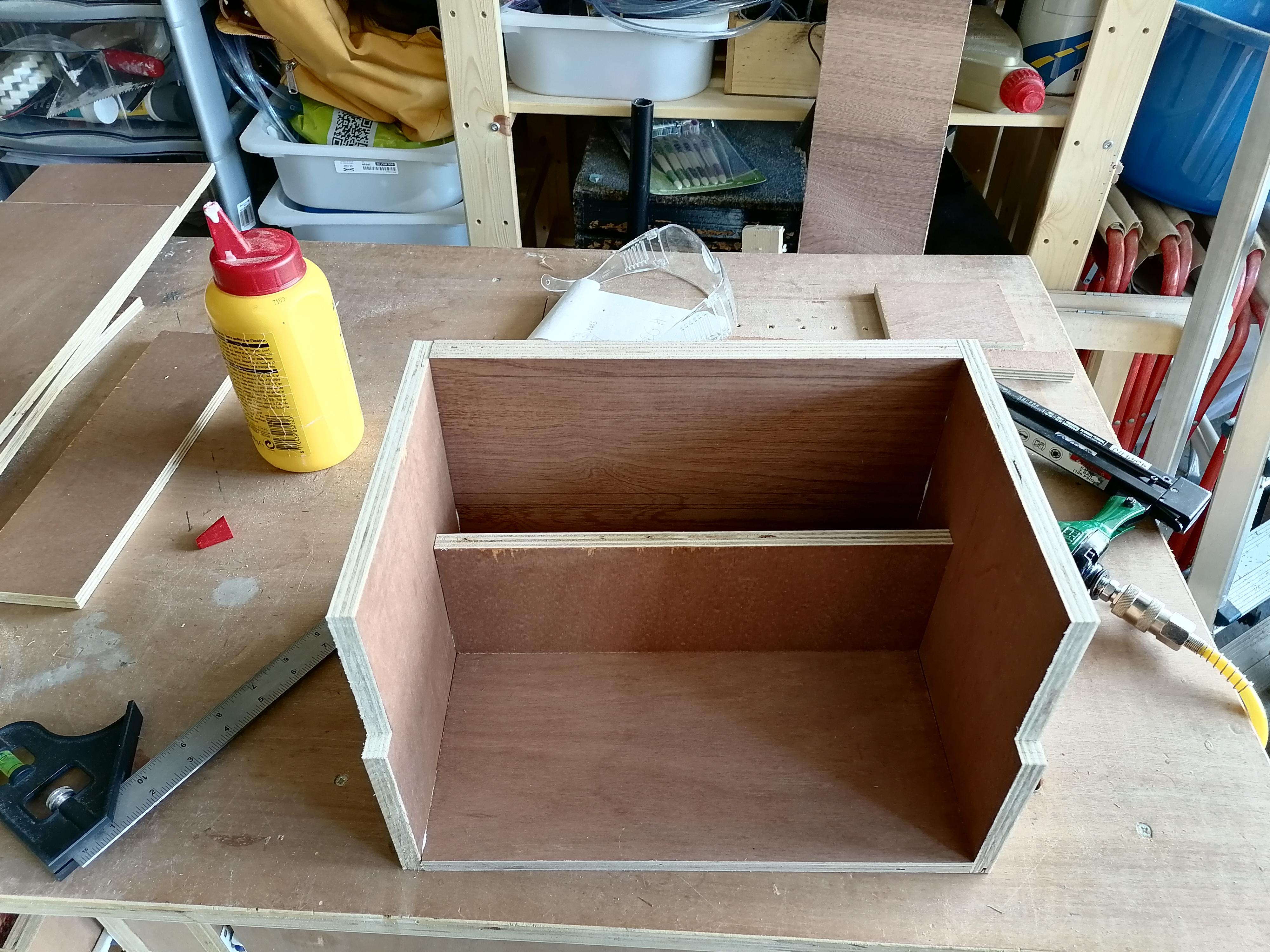
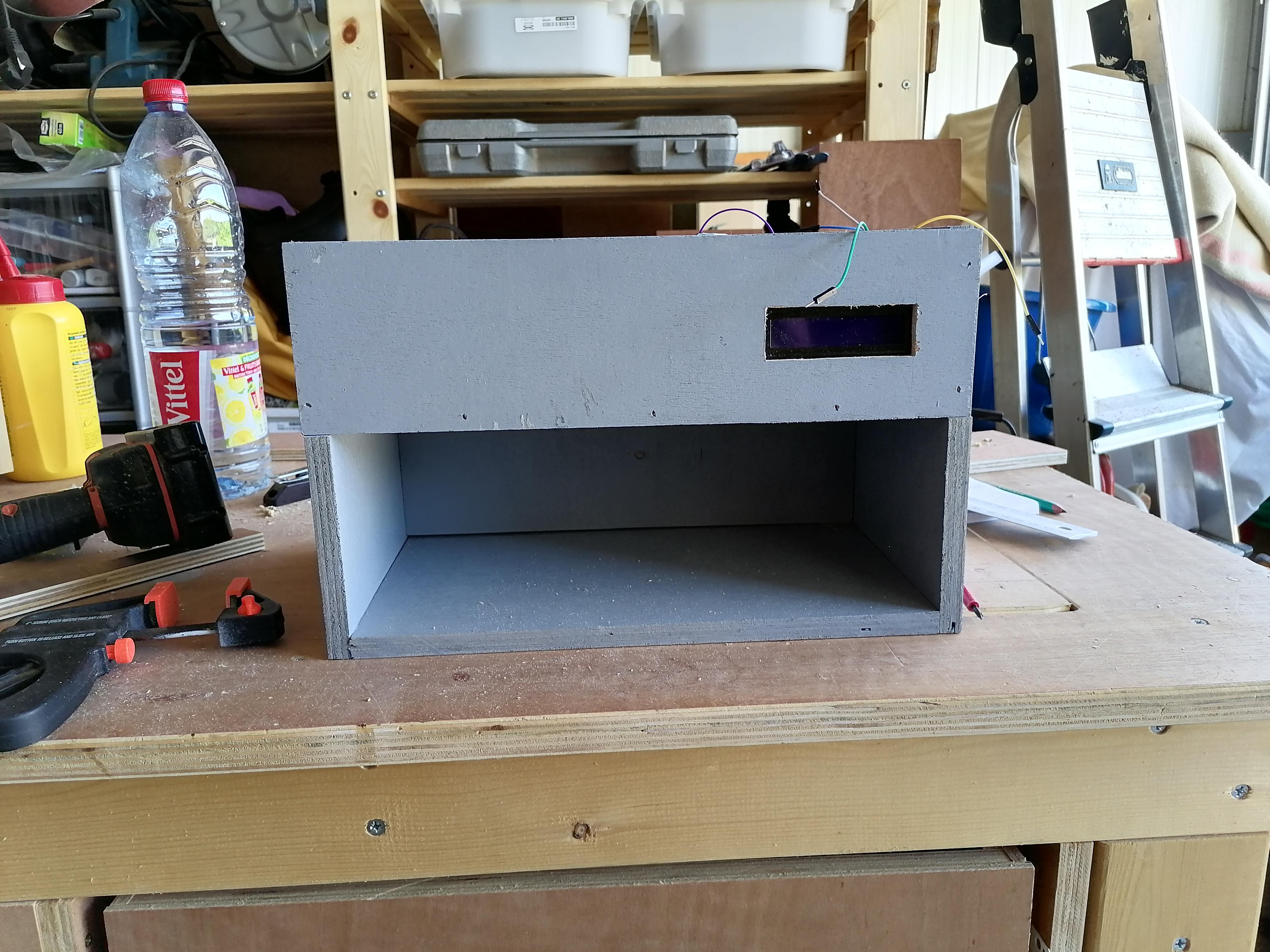
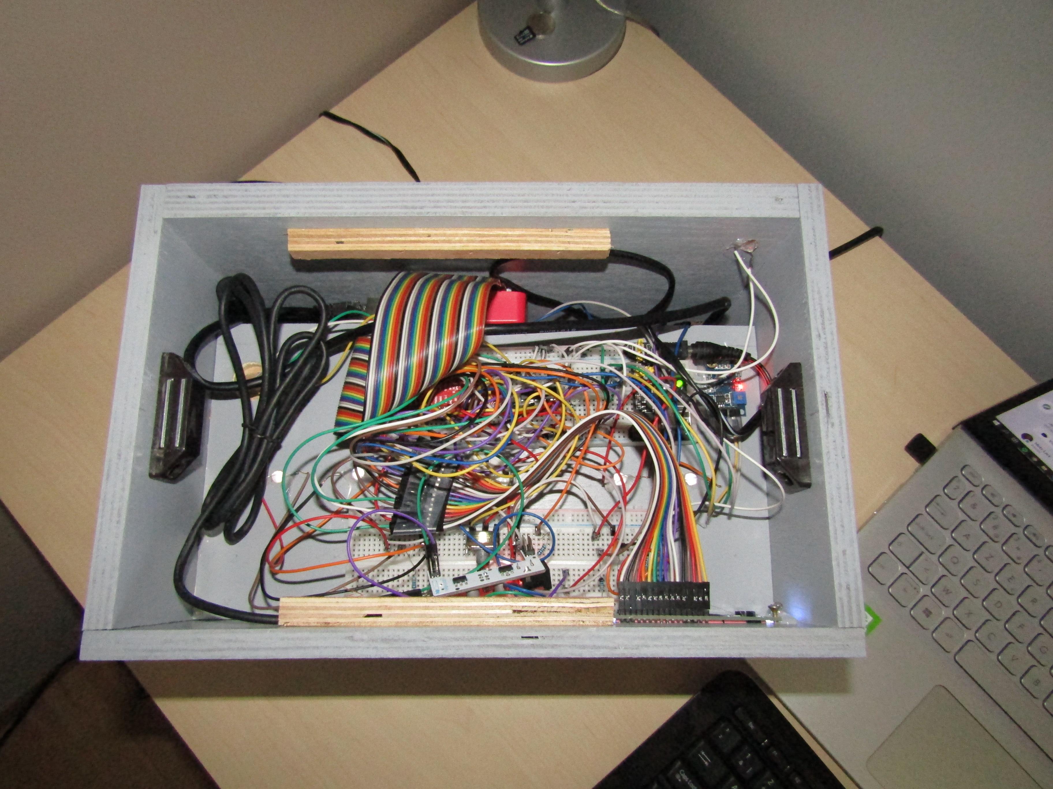
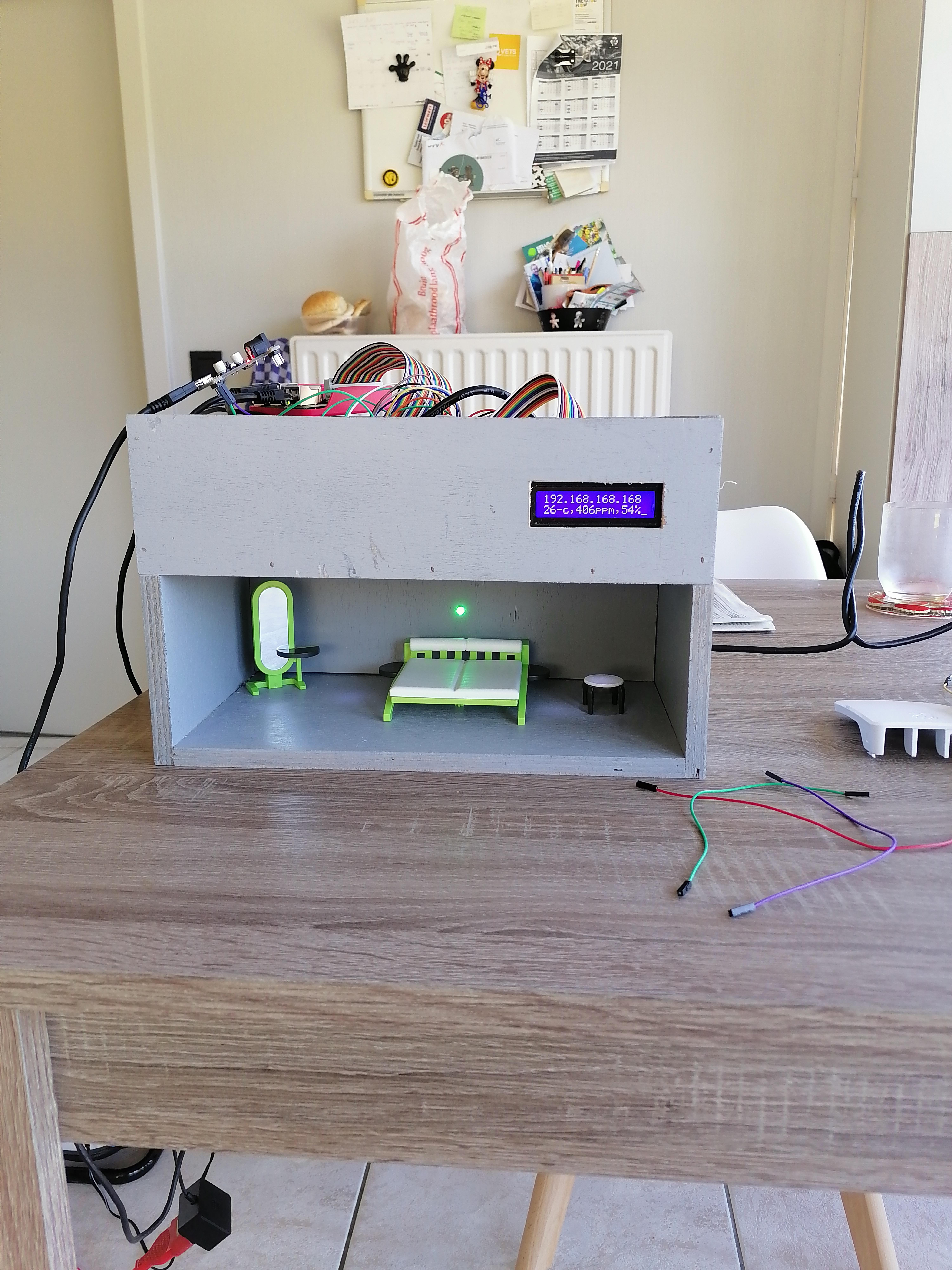
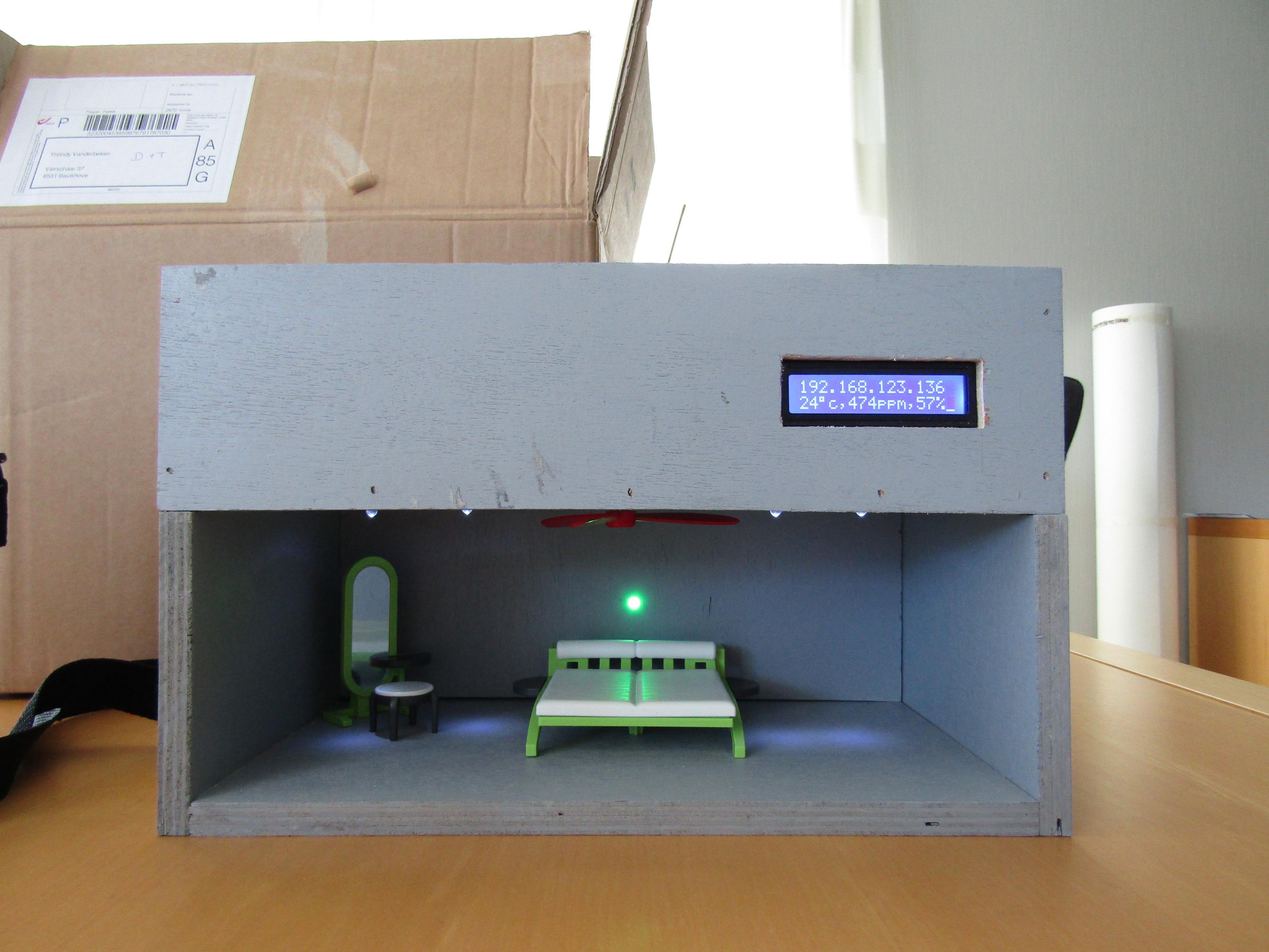
The last step of my project was to build a nice case/house for all the electronics. I first drew my sketch on paper berfore I started working on it. It was a bit gabbling to choose the right sizes of the wood, because we had to put the whole electrical circuit in it. In the end it turned out that I had chosen the right sizes.
The house is built completely of wood. To keep the wood toghether, I first used wood glue. After the wood glue was dried, I also used a compressed air stapler to keep everything together.
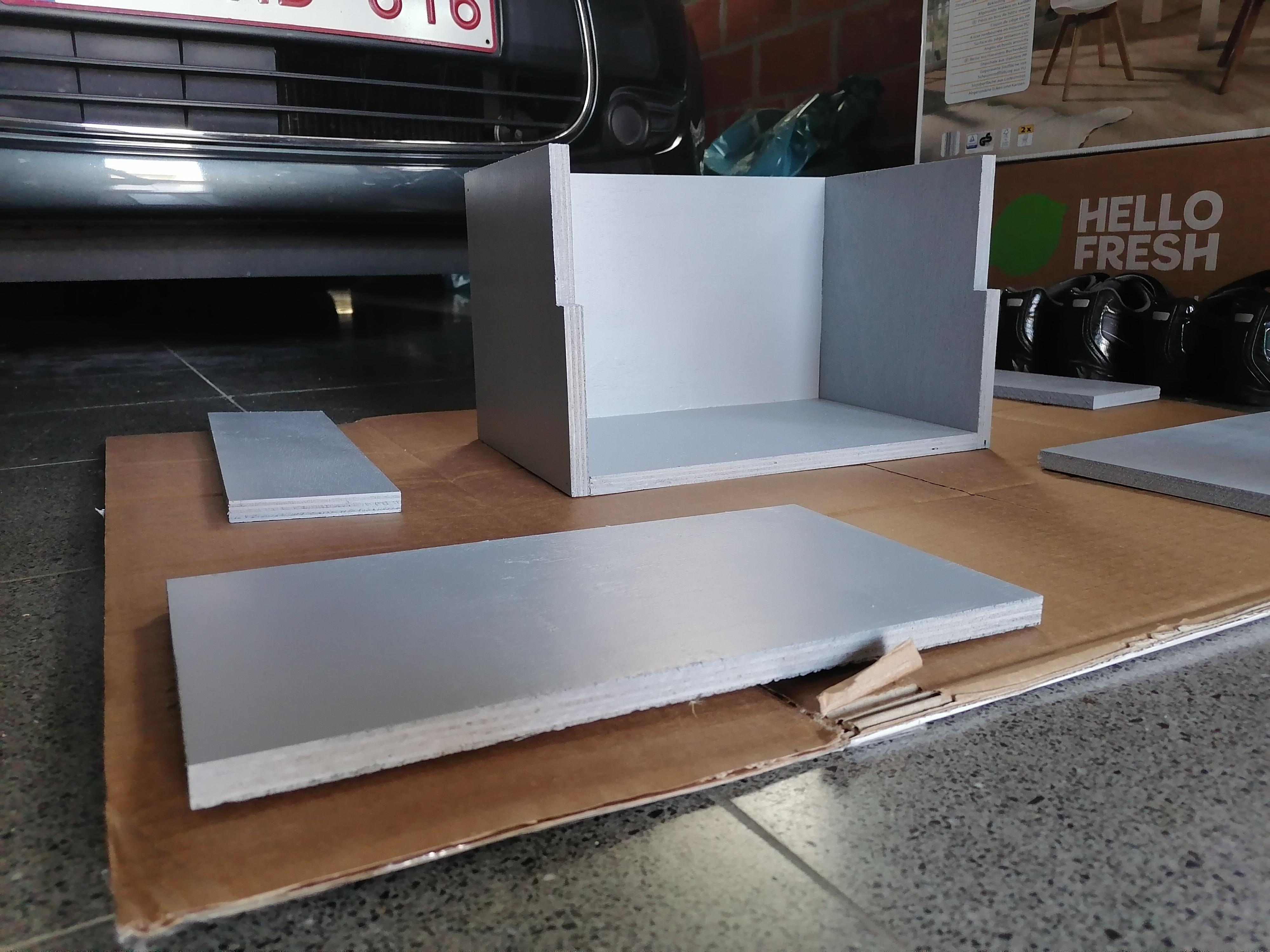
After that the exterior walls where glued, I used a primer to have a good first layer on the wood. After that the primer was dry, I painted the wood in a light grey color.
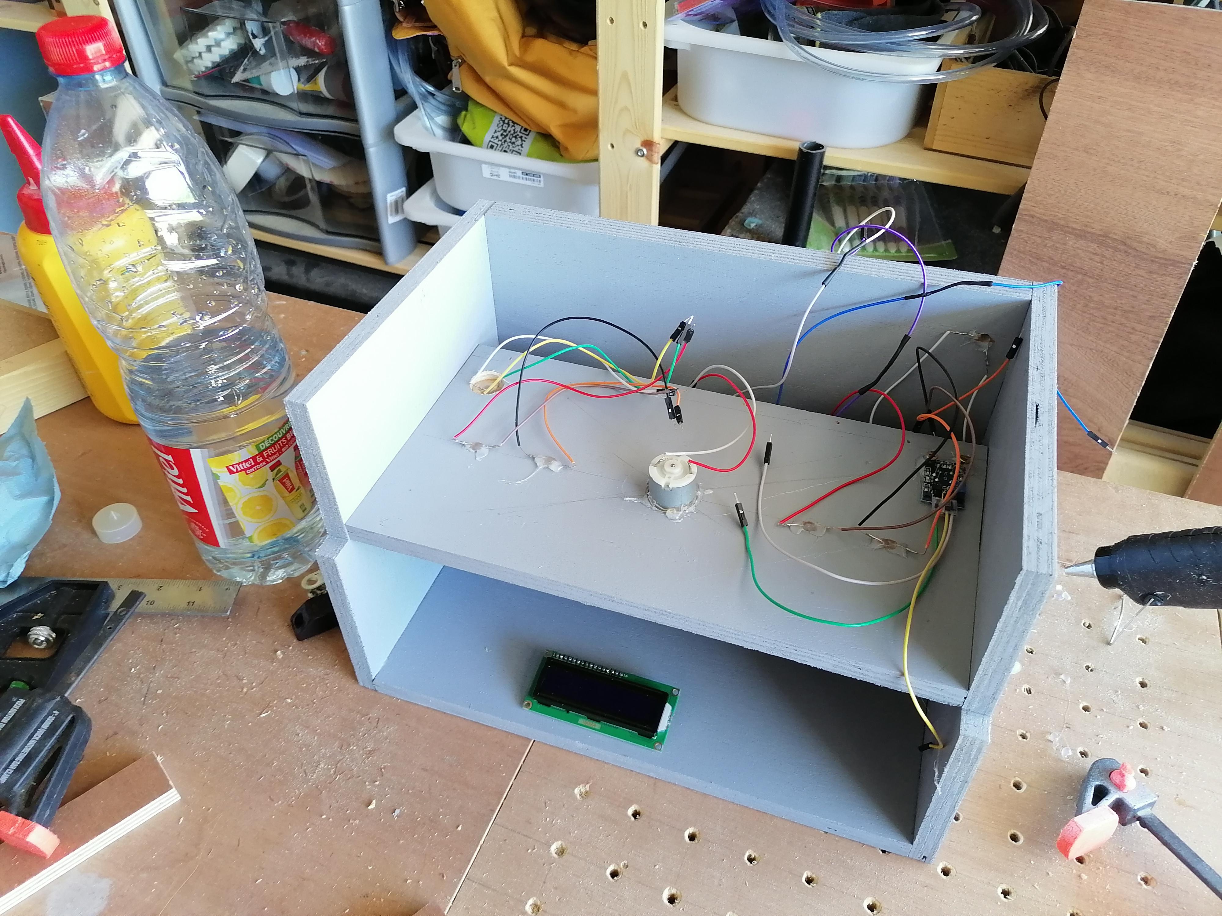
After the painting work, it was time to glue al the electronic components in the wood. I also used a drill to make holes in the wood. On the fourth picture you can see that everyting is glued.
Then it was time to put the breadboard and the Raspberry Pi in the house. On the fifth picture you can see that everything is implemented. The cable management is not the best but it works fine.
On the last 2 pictures you can see that case/house is ready!