Smart Robot Car Kit
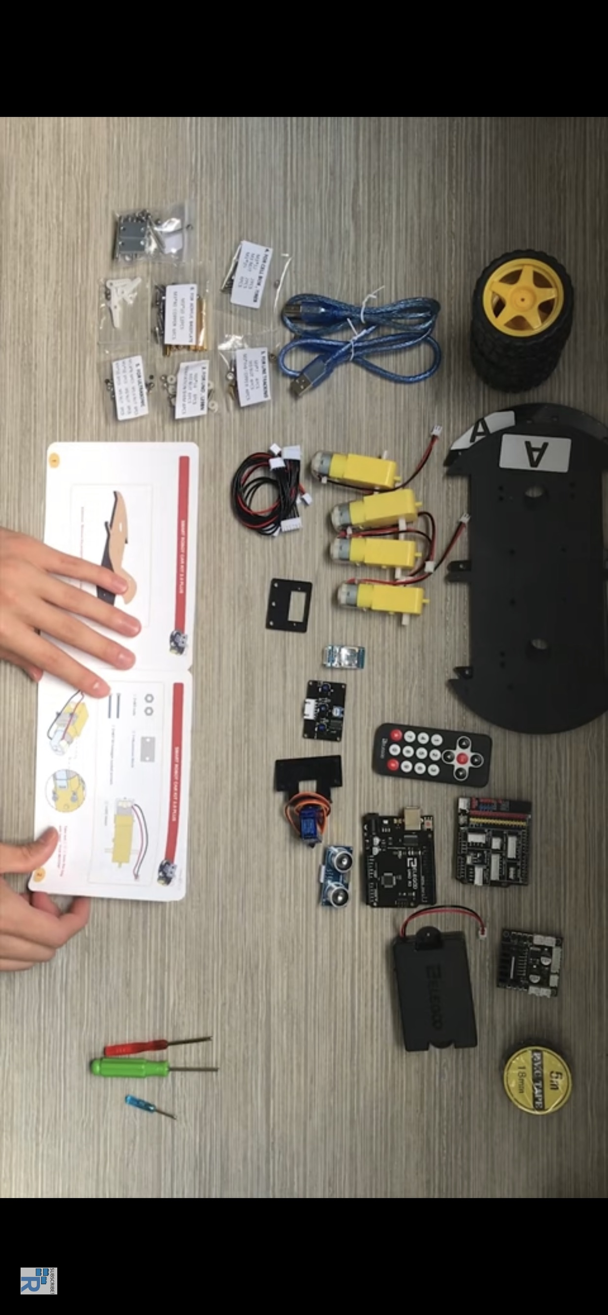
Gather all your equipment along with your instruction manual. You should have:
4 DC motors
2 Acrylic chassis
M3 nuts
Aluminum blocks
Hexagon socket screws
1 L298N
Separation shims
Line tracking module
IO expansion board
R3 Board
Bluetooth module
Ultrasonic sensor module
2P, 4P, 5P, and 6P cables
4 Tires
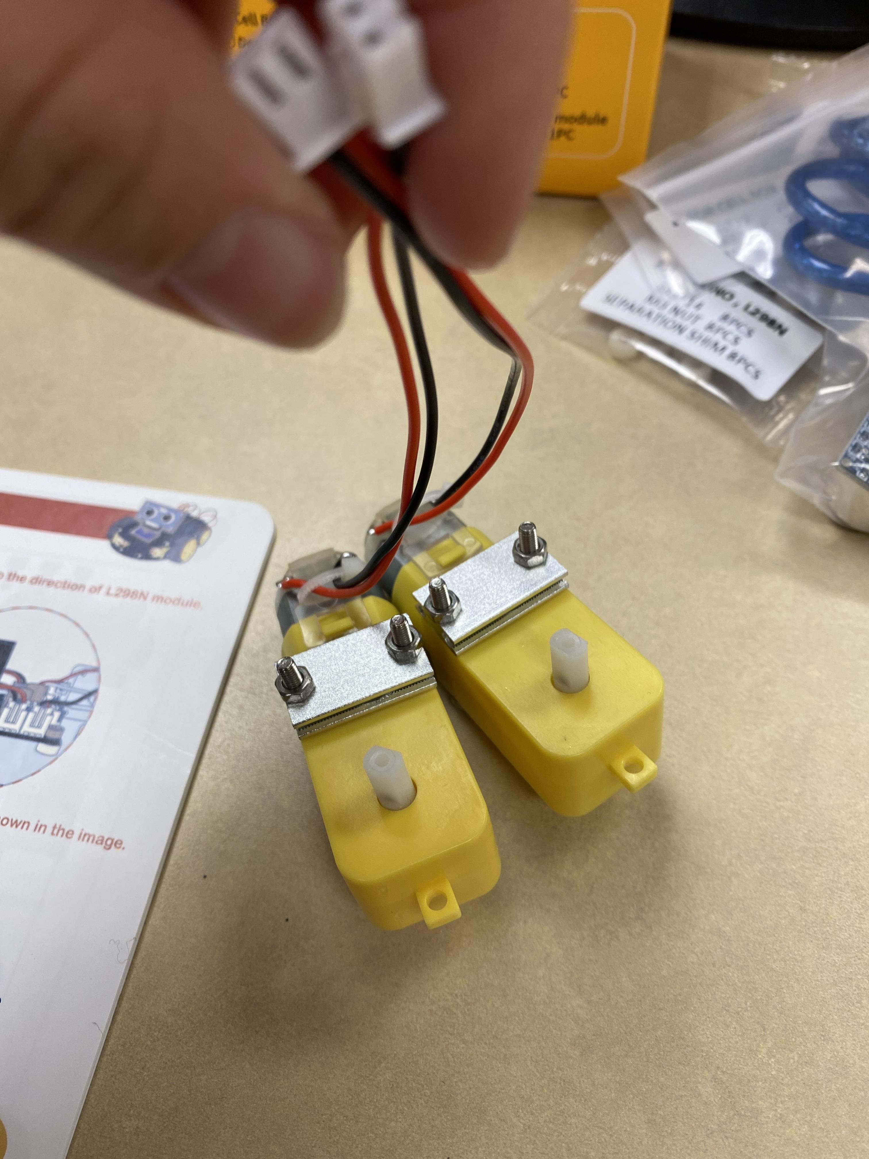
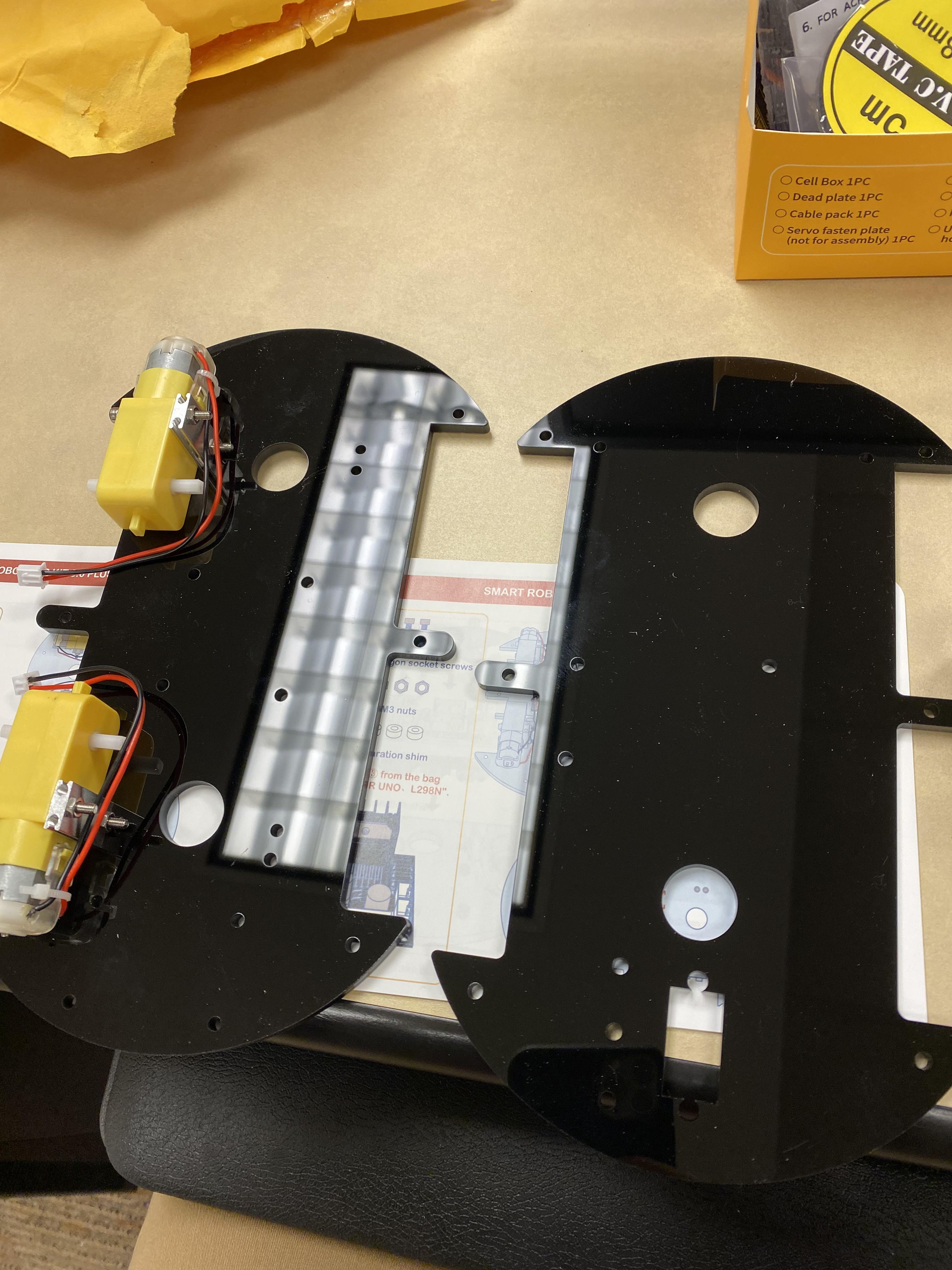
Start by removing the protective film off the acrylic chassis.
Take your DC motor and screw it in to the sockets in the acrylic chassis.
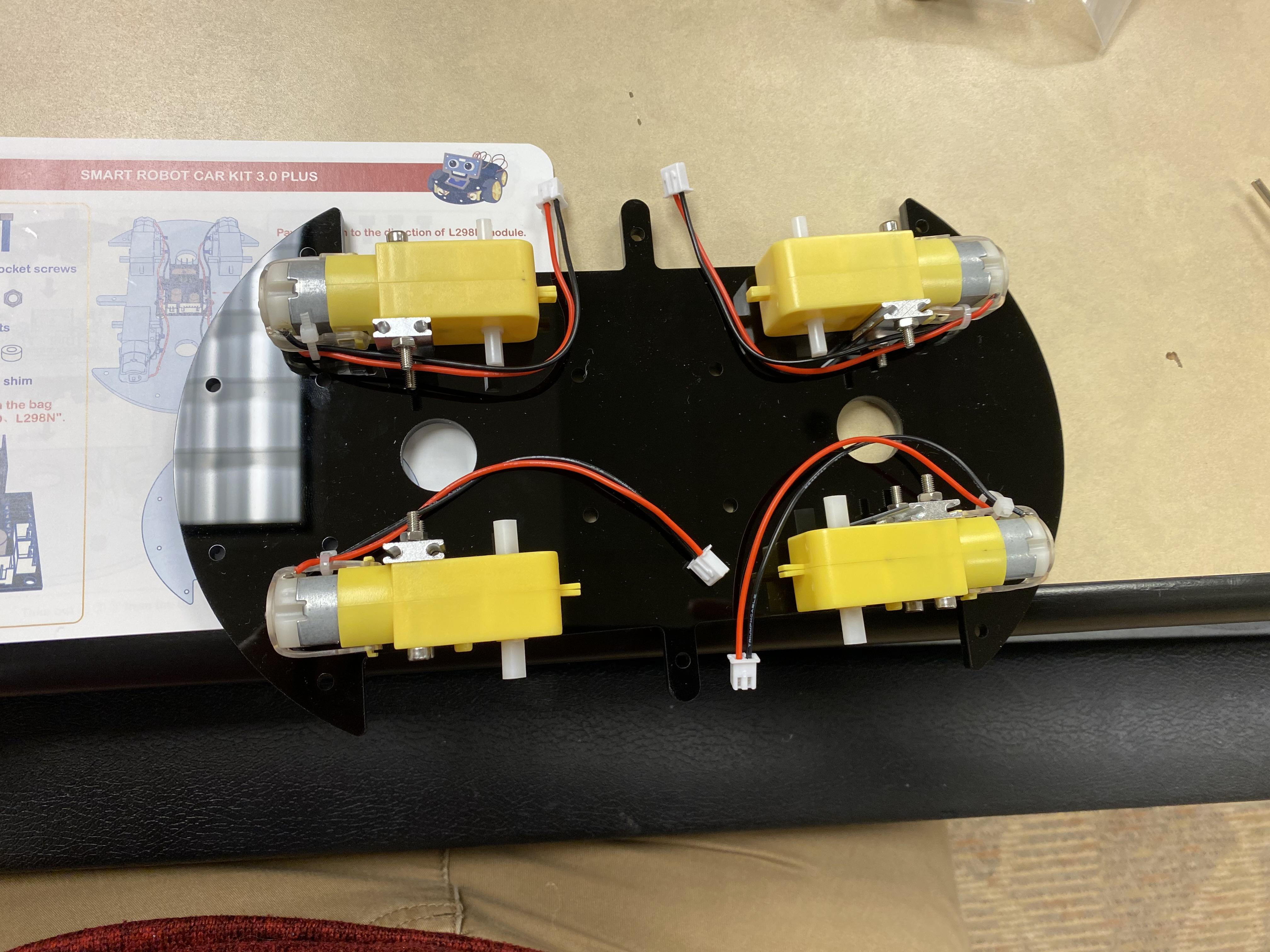
Make sure the silver tips of the DC motor are pointed outwards and your cables all connect in the middle.
L298N
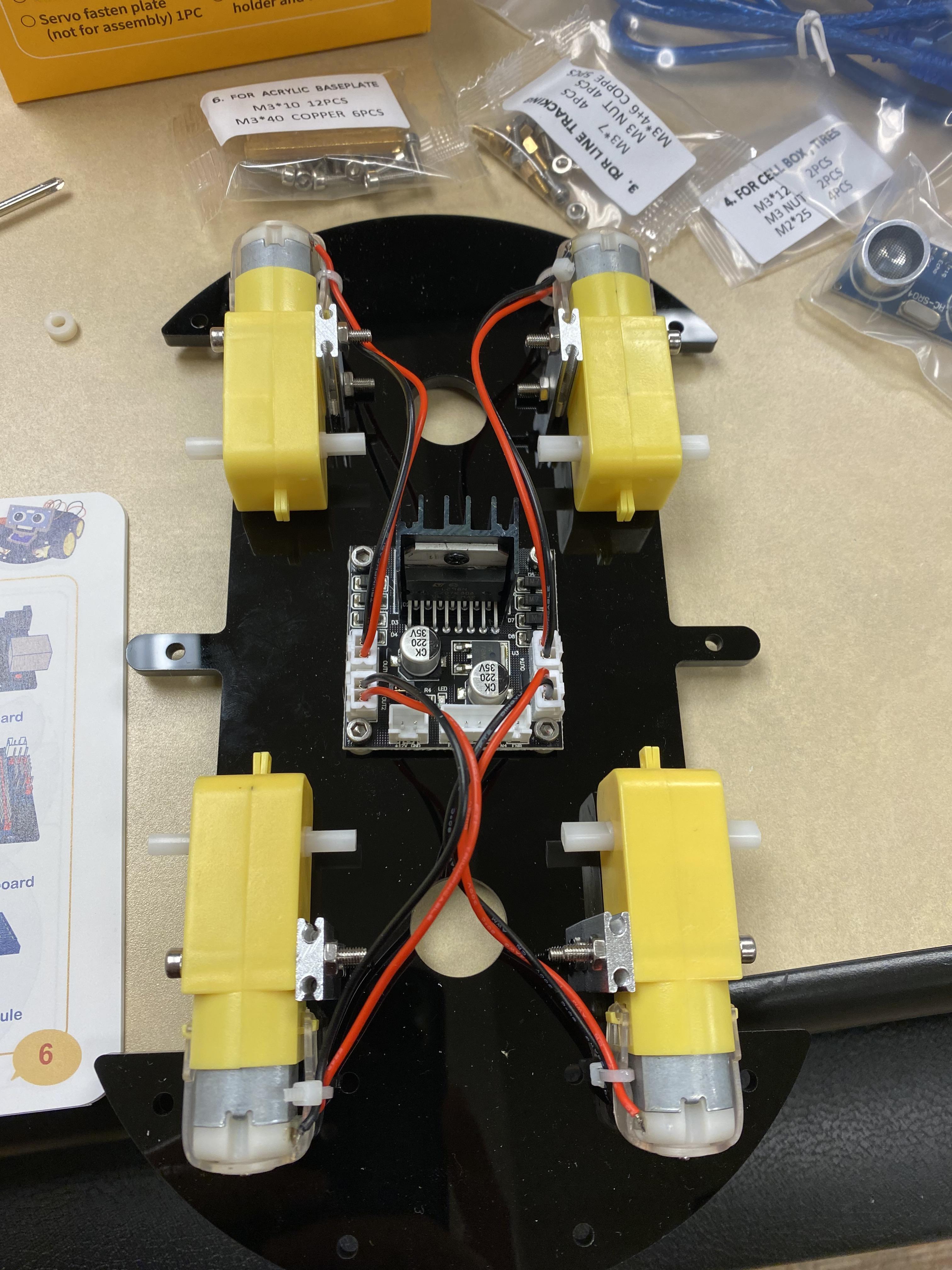
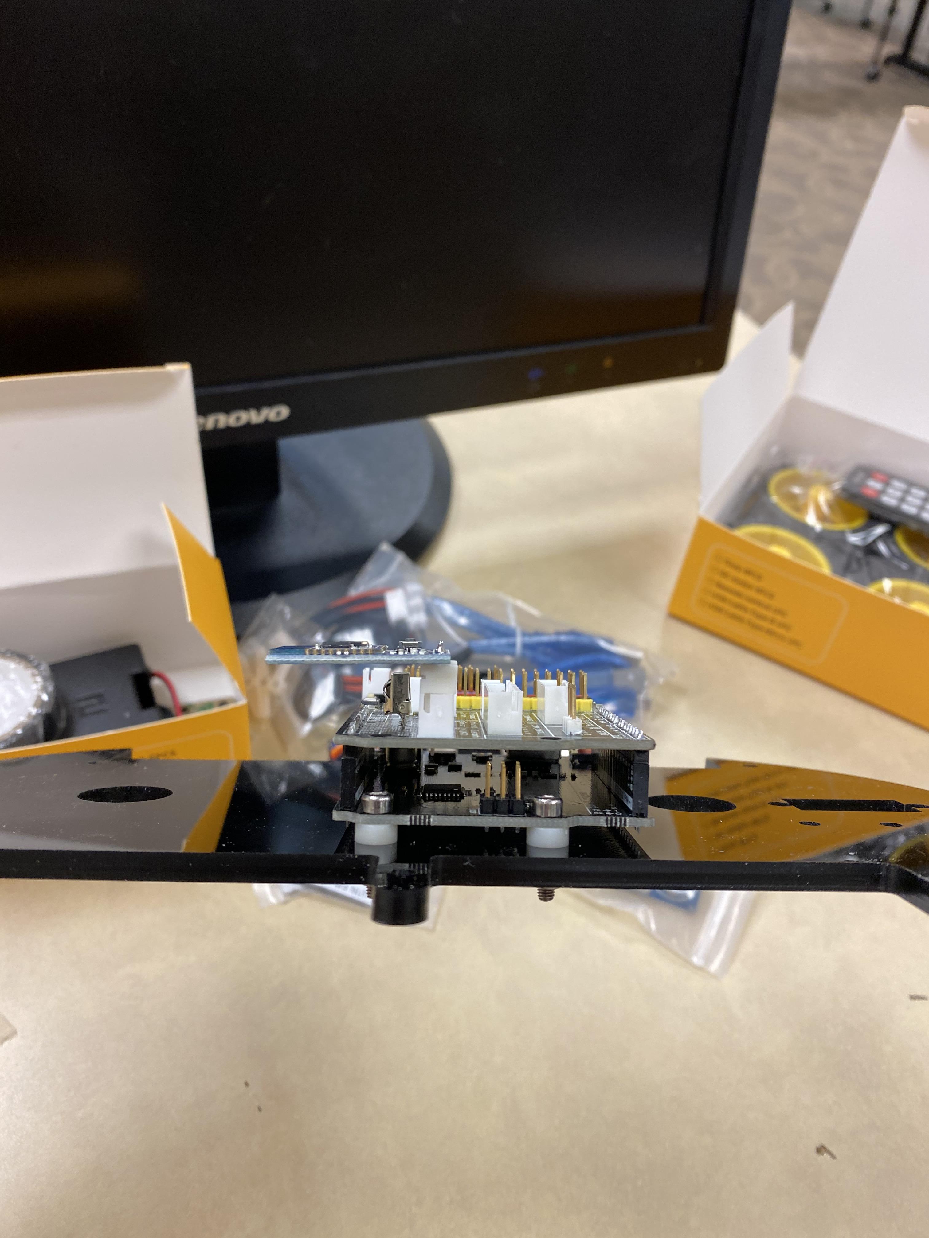
Now you need to screw in the L298N into the middle of the acrylic chassis as seen in the image. Make sure you pay attention to the direction of the L298N. Once that is done go ahead and connect your wires like in the picture.
Install Line Tracking Module.
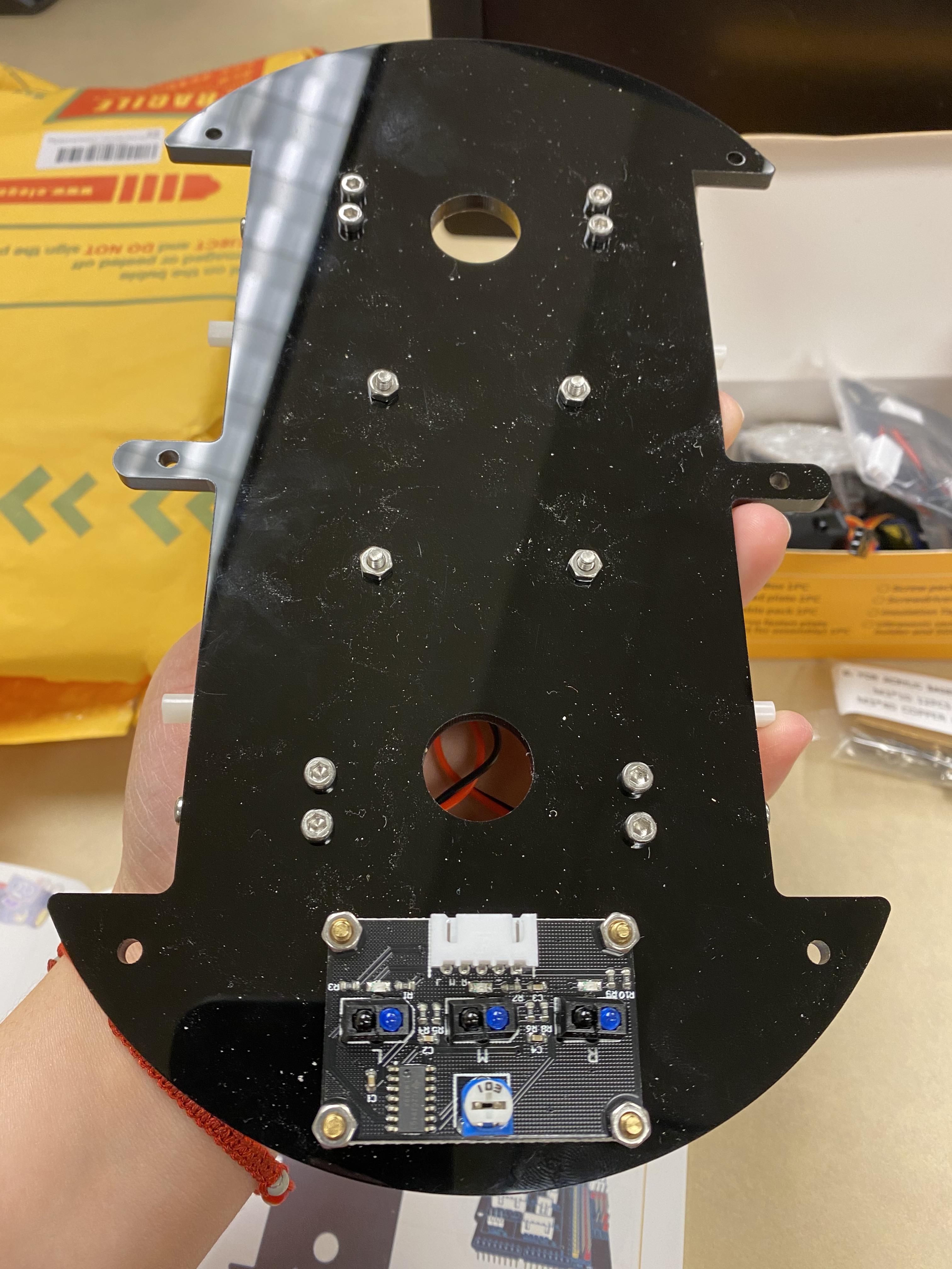
You need to screw in the tracking module to the bottom of the chassis as shown in the image.
Installing UNO R3 Board
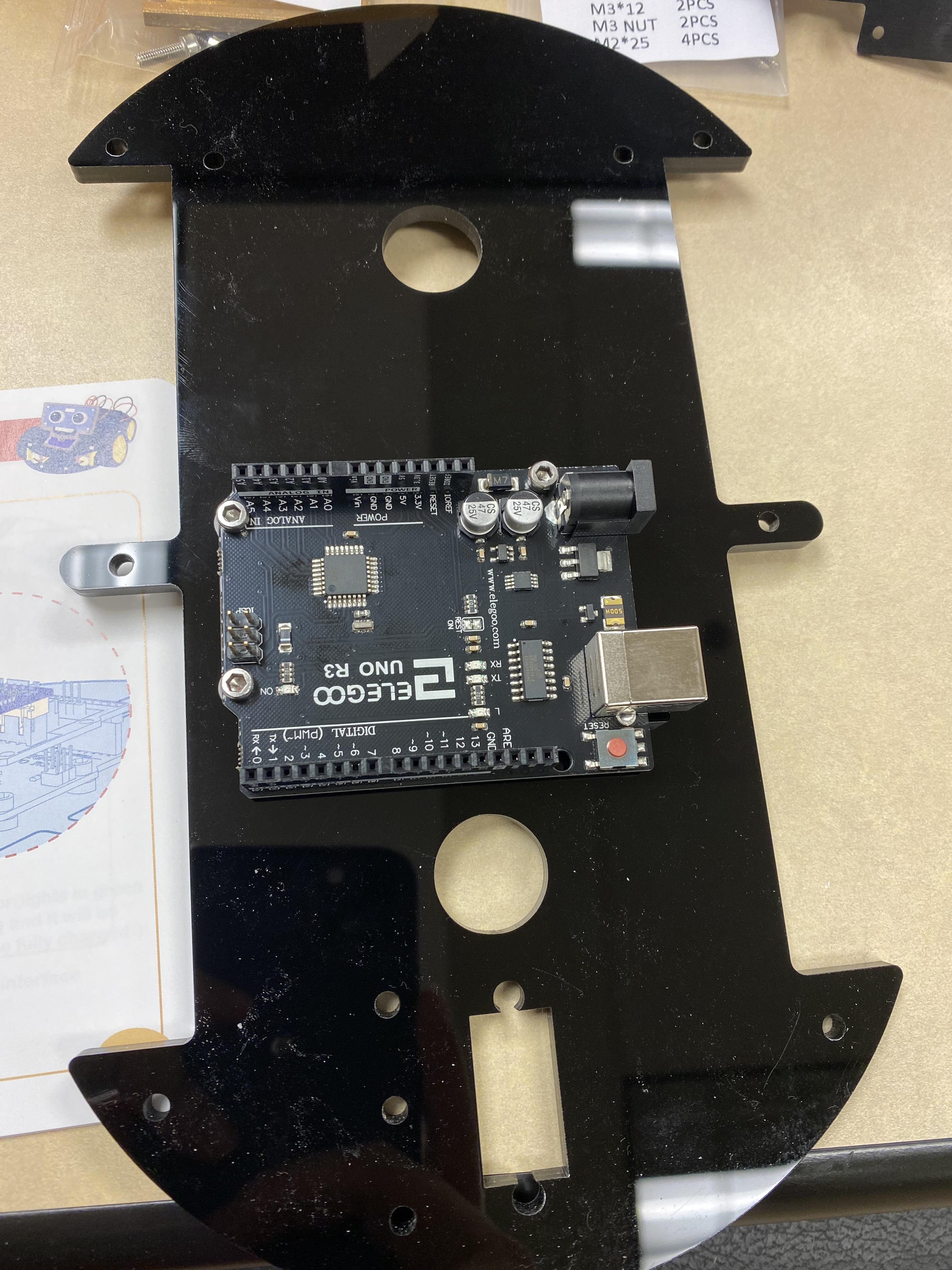
On the other acrylic chassis you need to screw in the UNO R3 Board. Do not forget to use the separation shimsto prevent from damaging the chassis.
IO Expansion Board
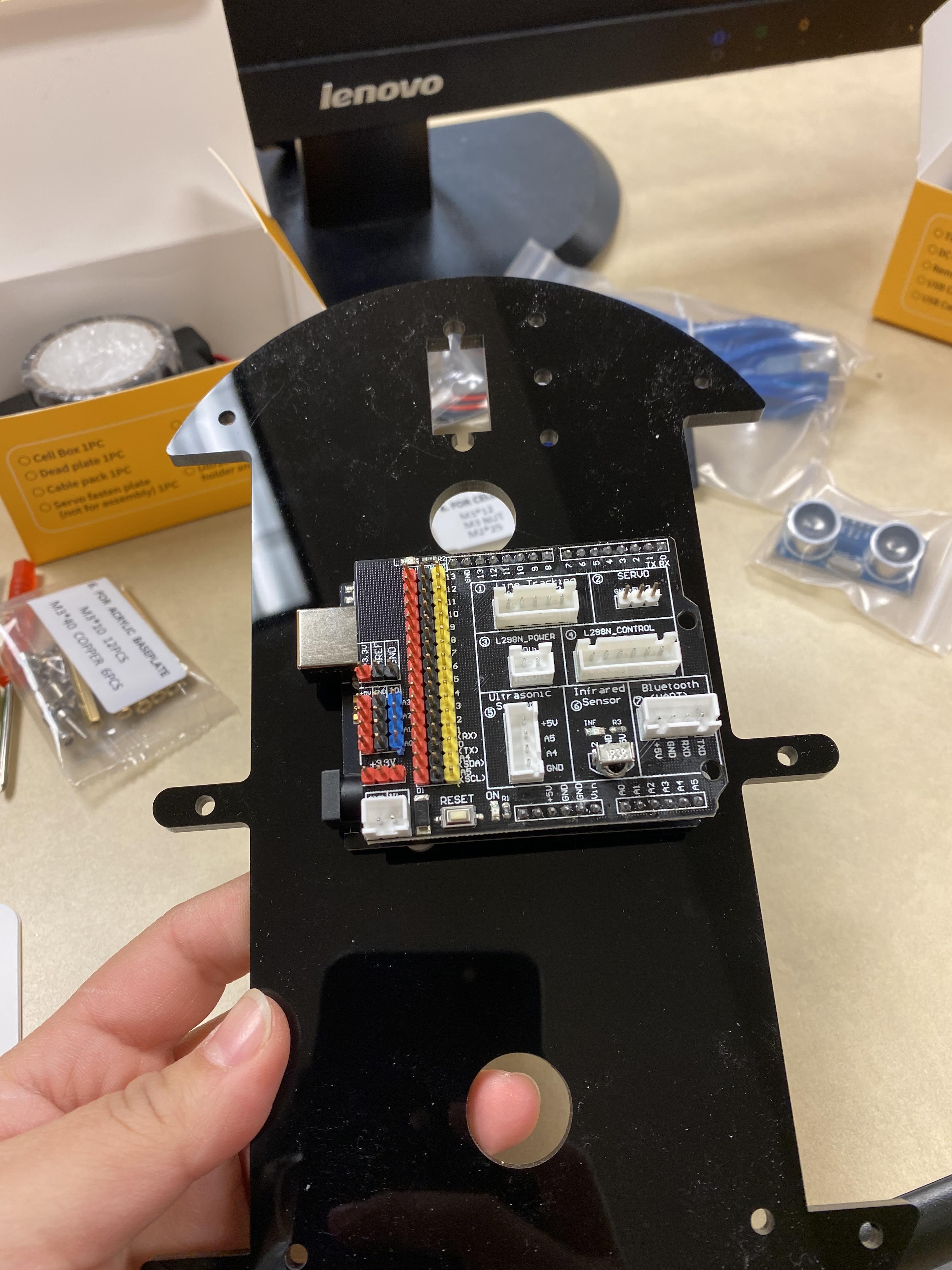
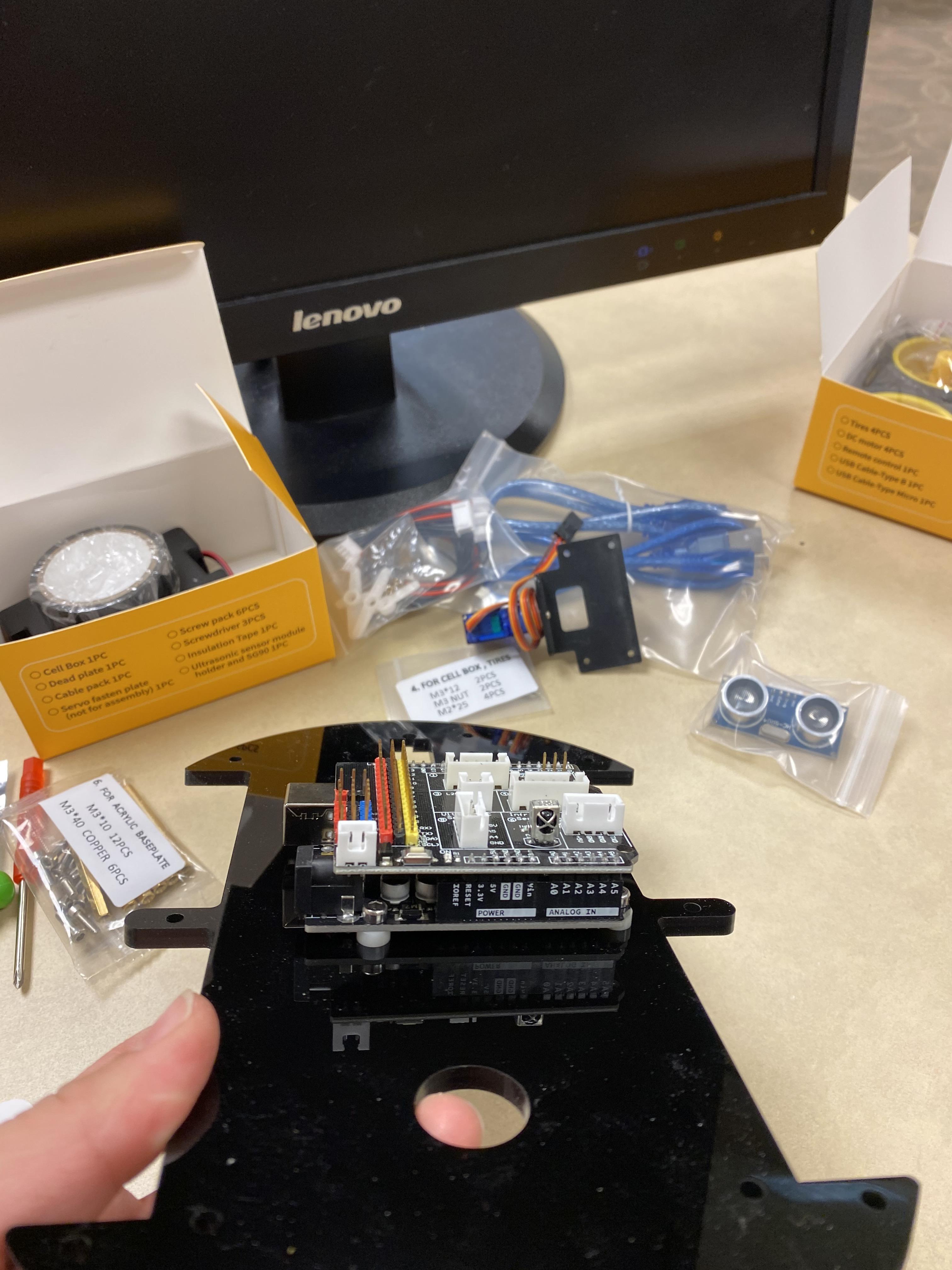
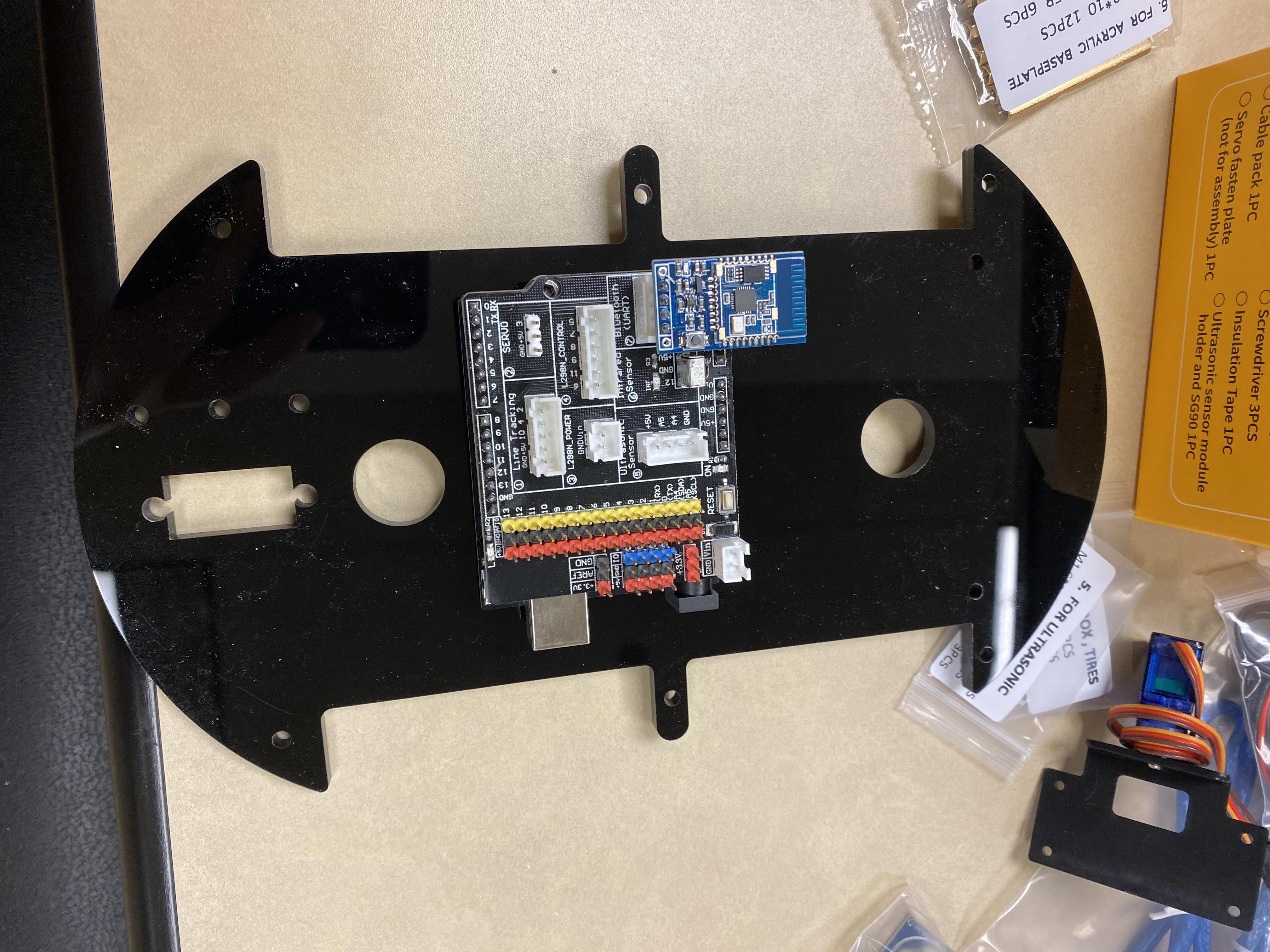
After installing the UNO Board you need to connect the IO expansion board, it should fit perfectly in the uno board. After that you can go ahead and connect the bluetooth module to the IO expansion board.
Battery
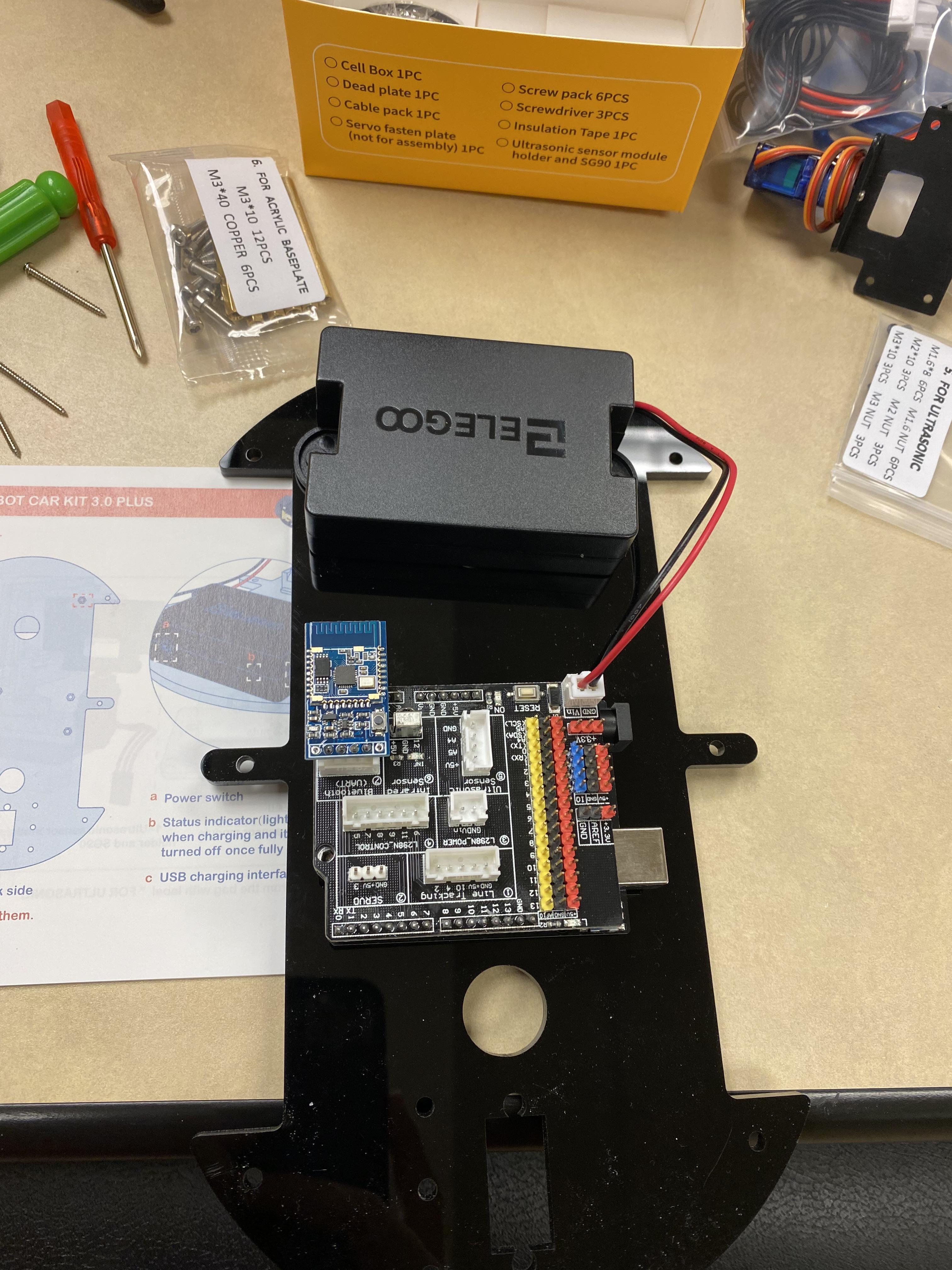
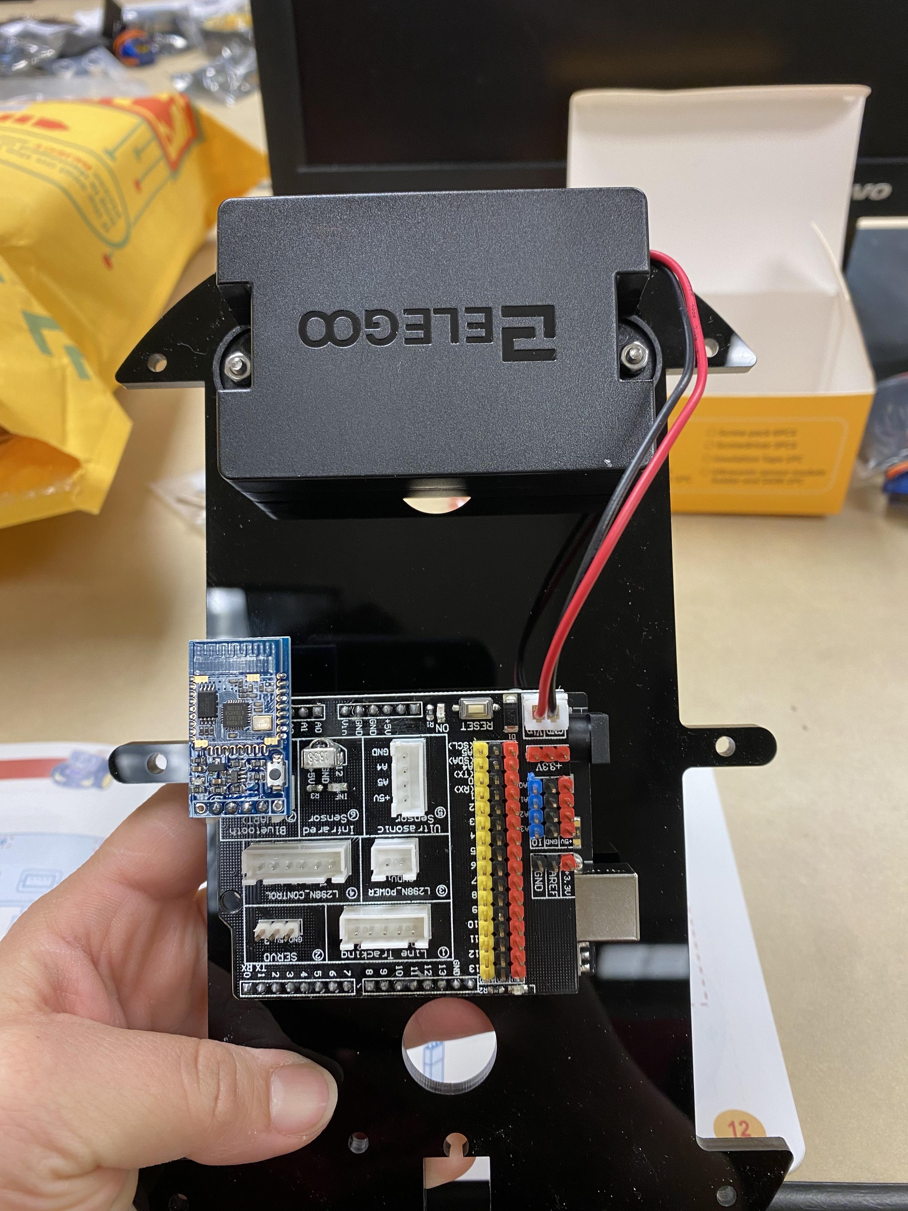
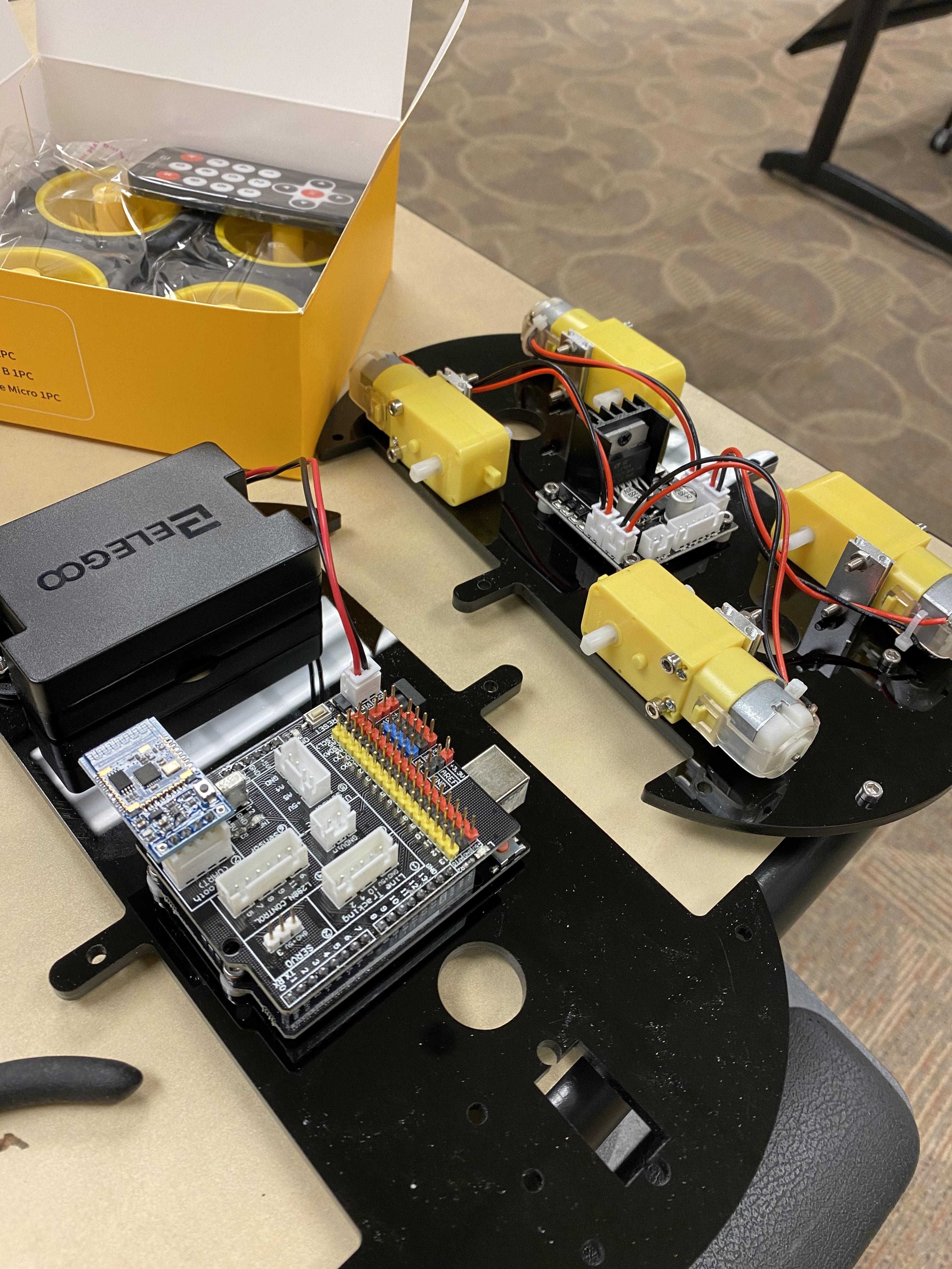
Position your battery then screw it in place. Make sure the wiring is in its corresponding slot on the expansion board. The battery light turns green when charging and turns off once fully charged.
Setting Up Ultrasonic Sensor Module
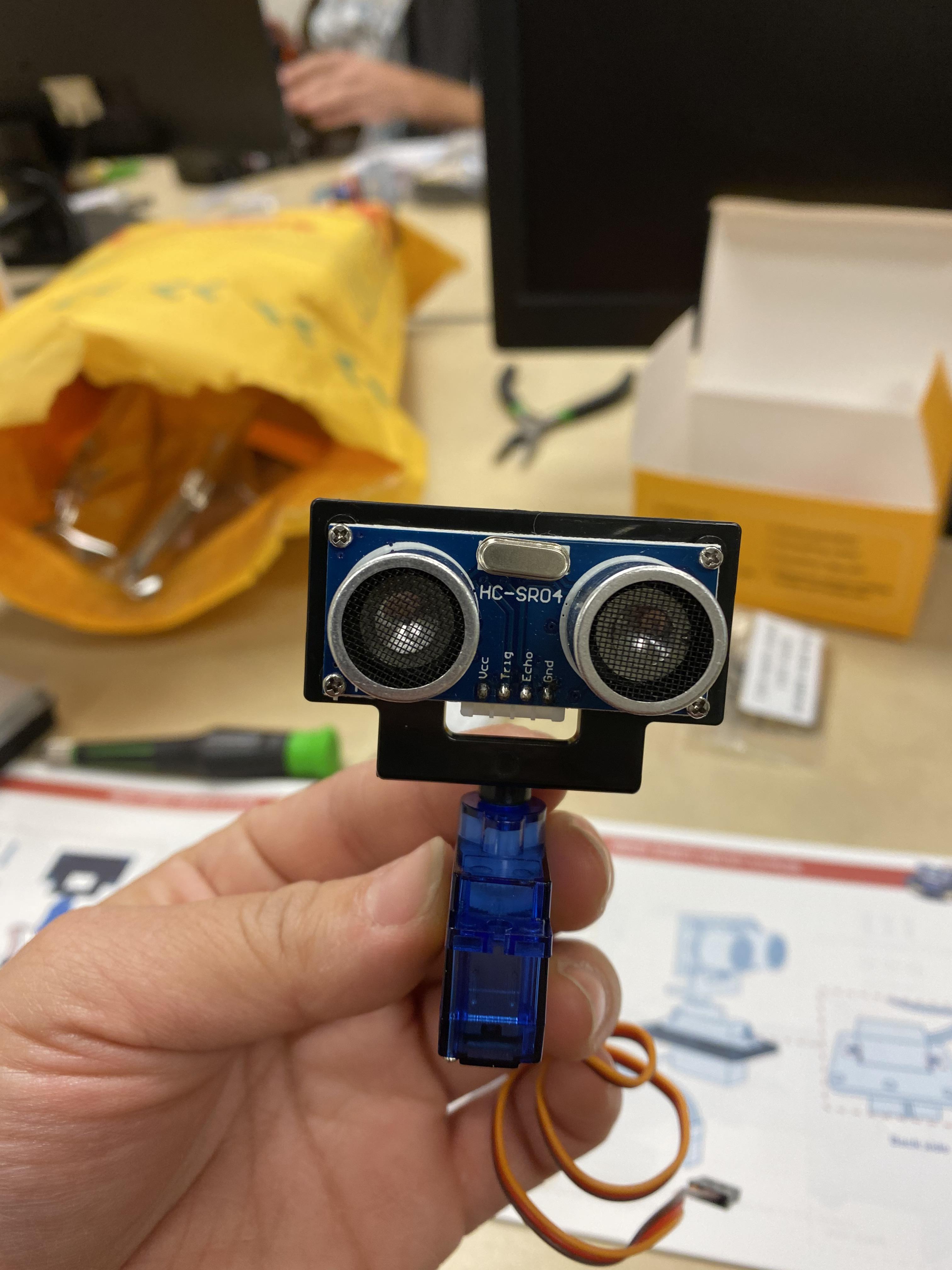
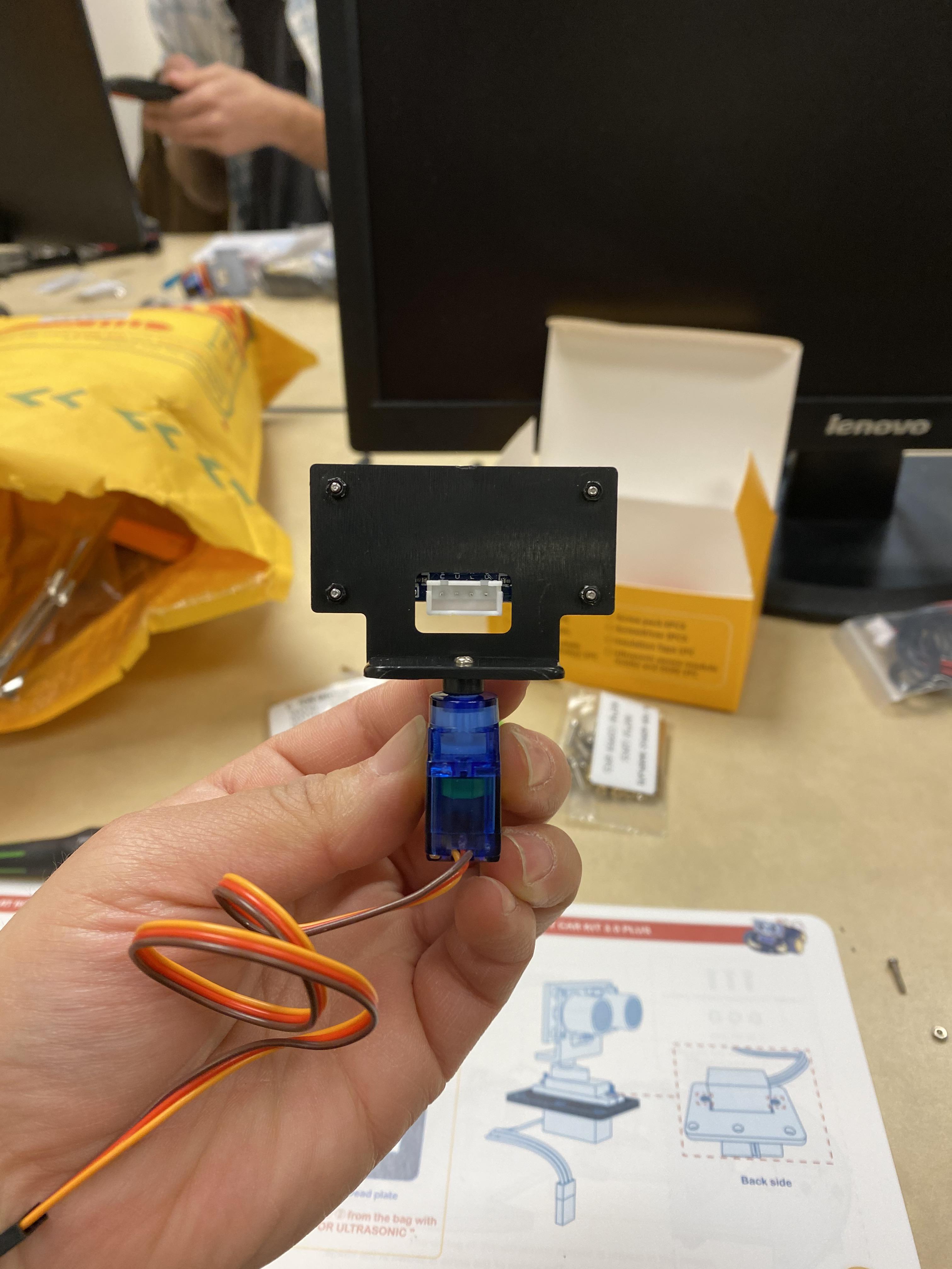
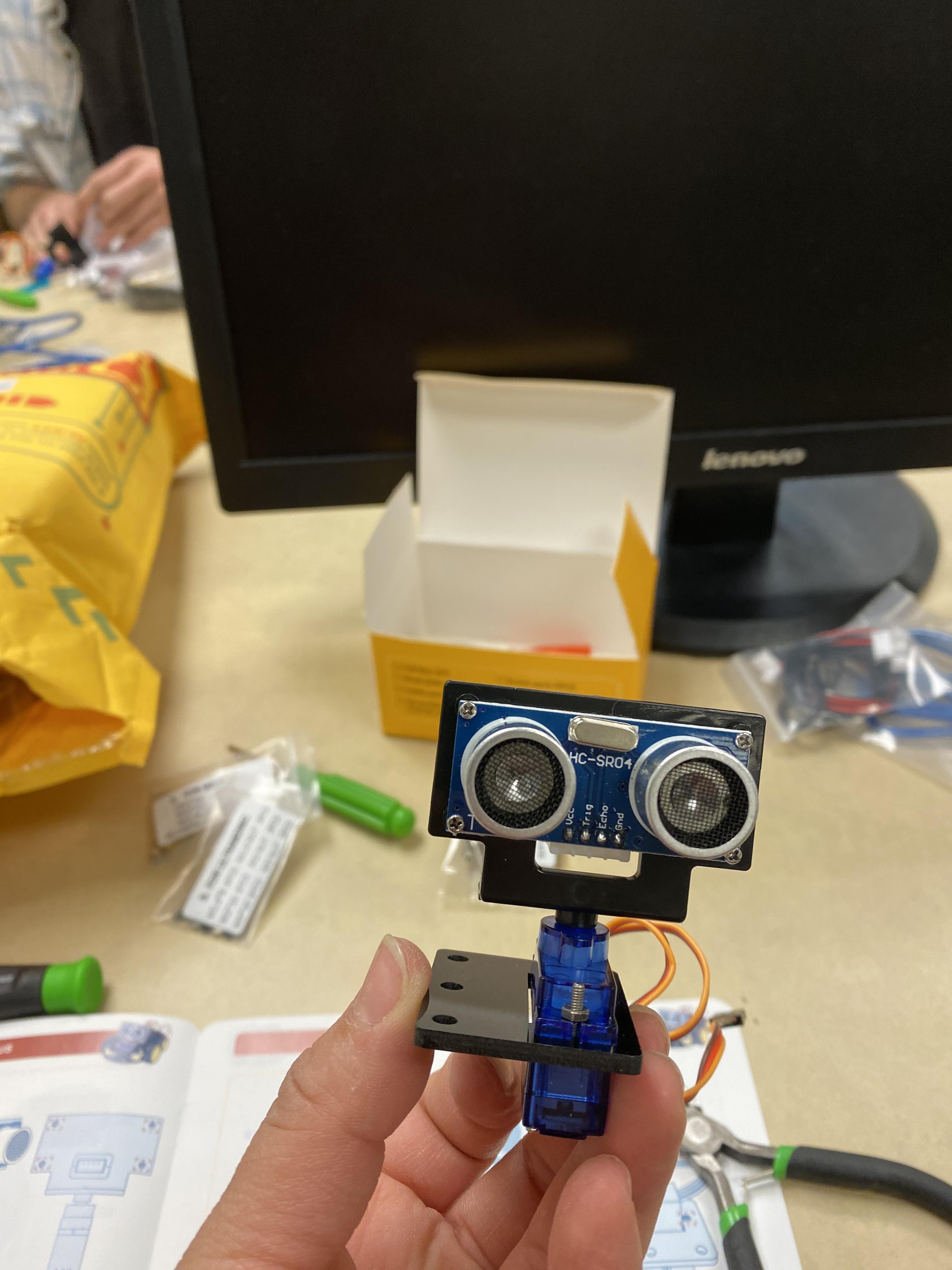
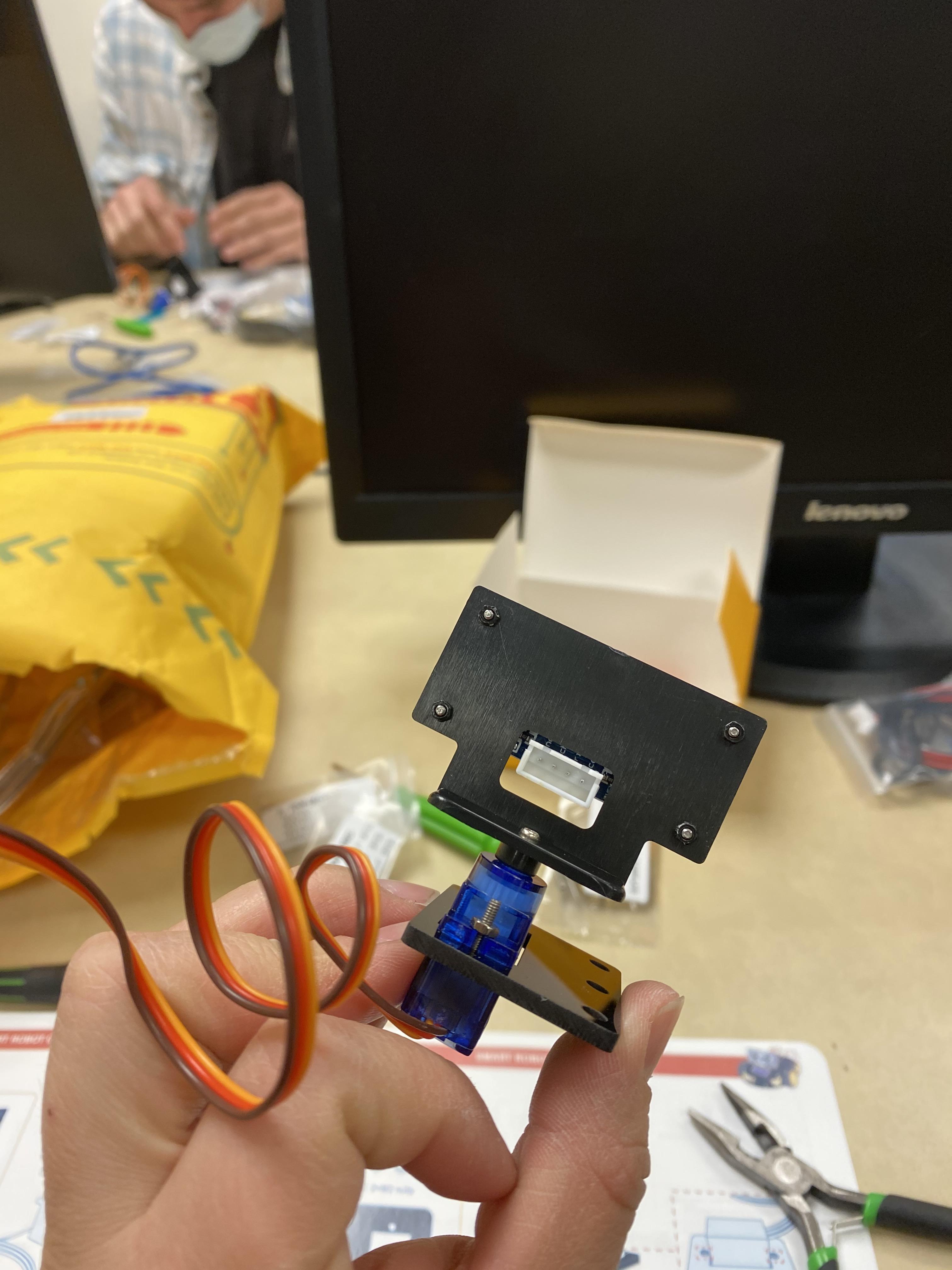
You will need to screw the ultrasonic sensor module to the holder using the tiny M1.6 cross screws. Than you need to screw on the dead plate and the final project should look like the image shown.
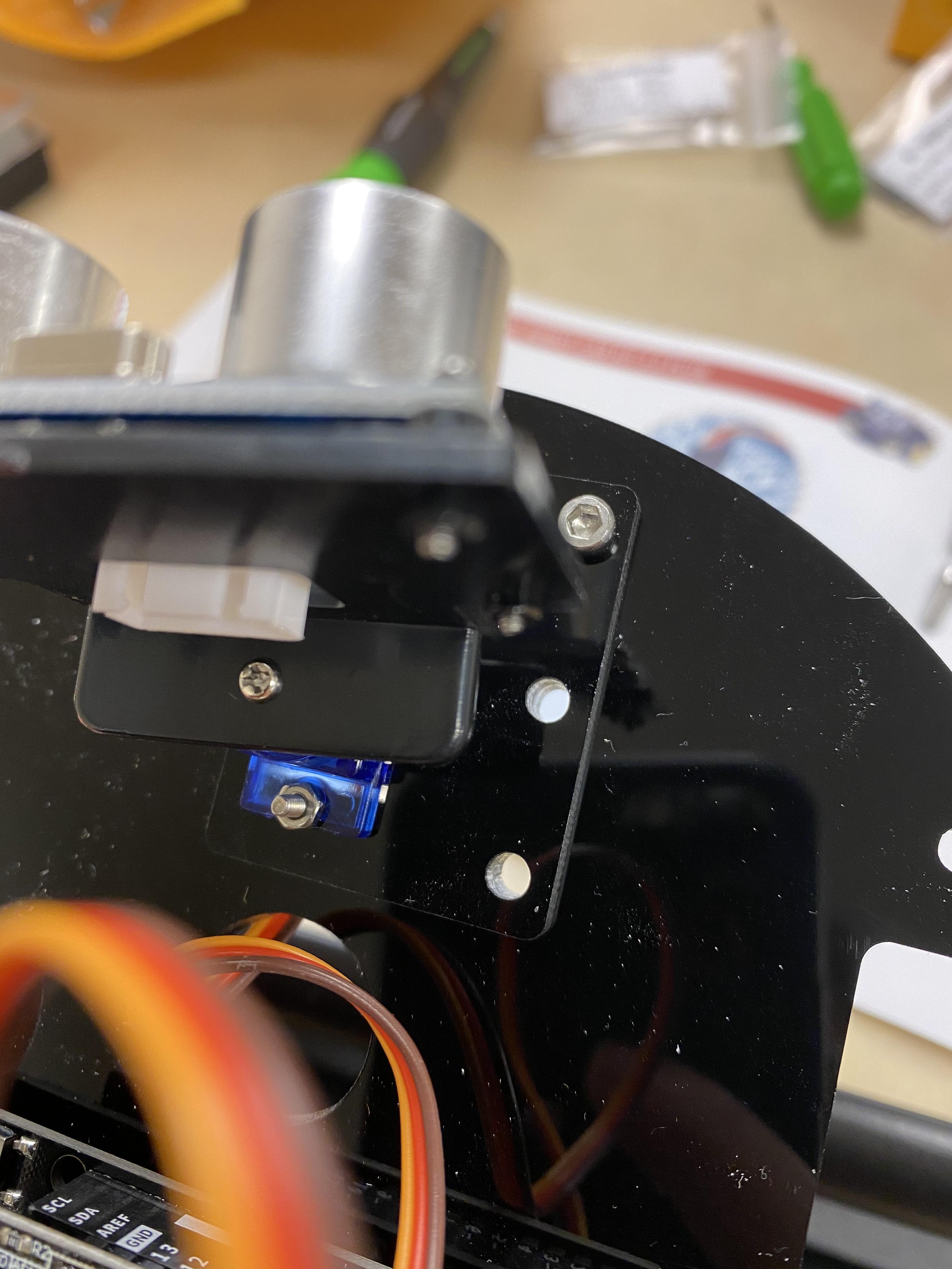
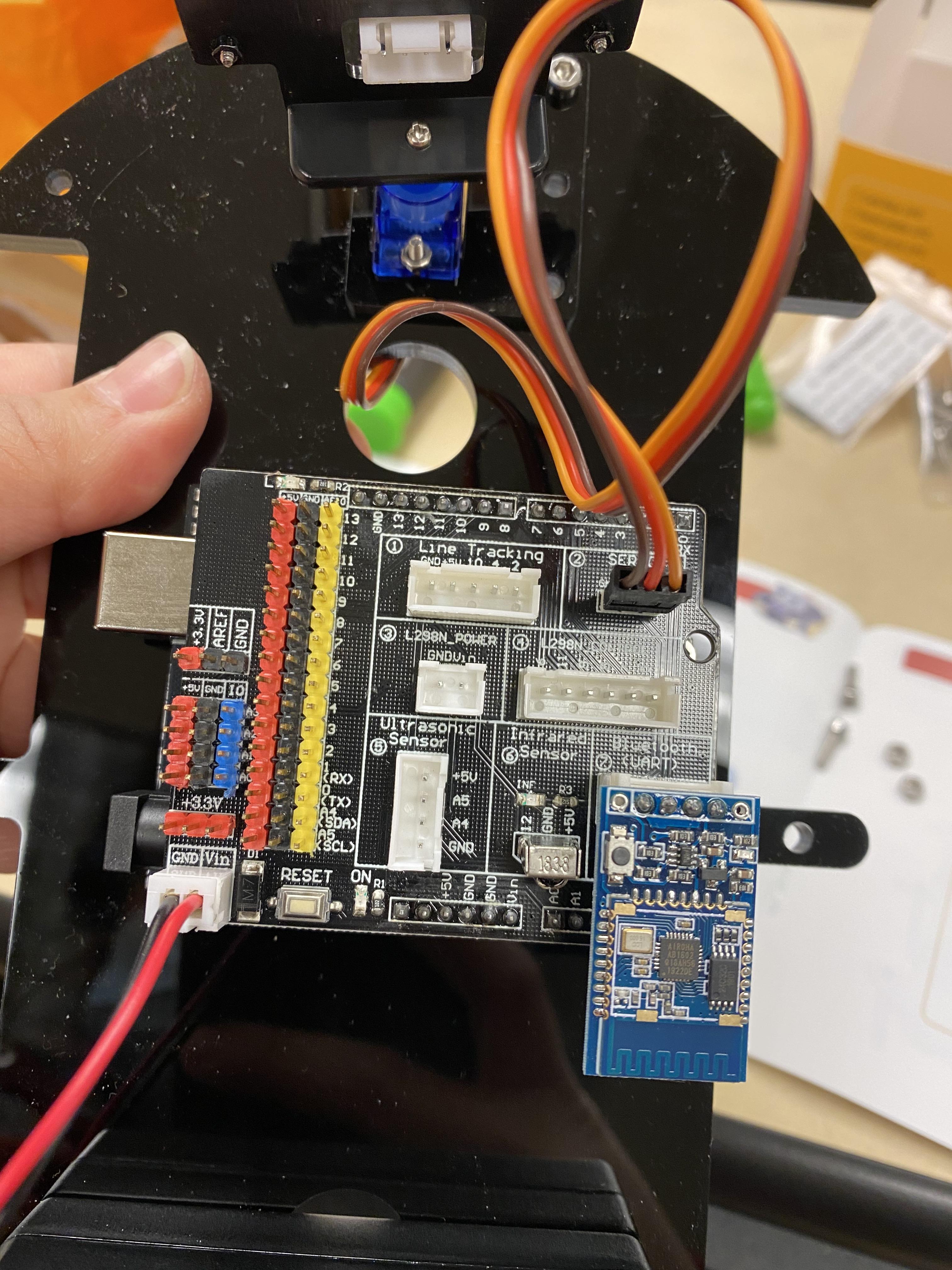
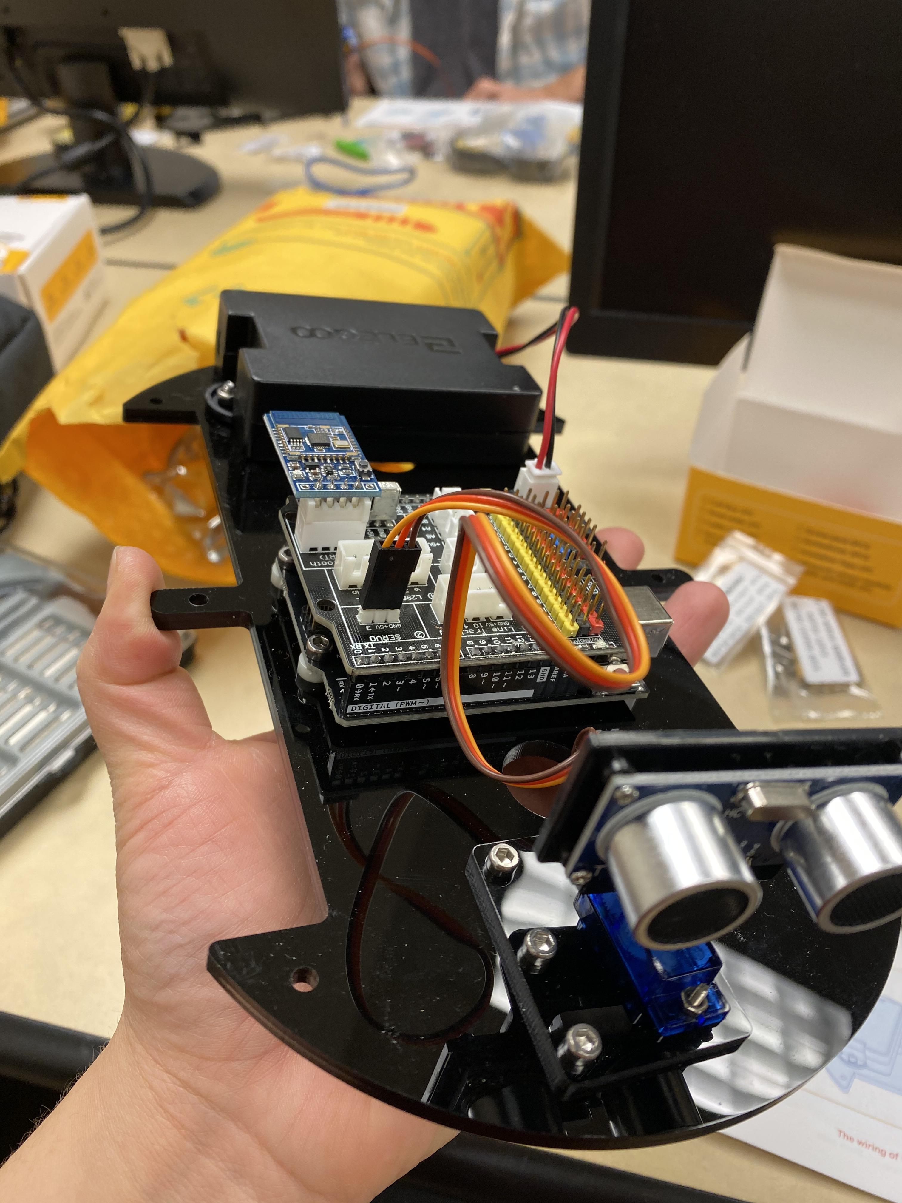
Loop the wiring up thru the hole in the chassis and connect it to its slot on the IO expansion board.
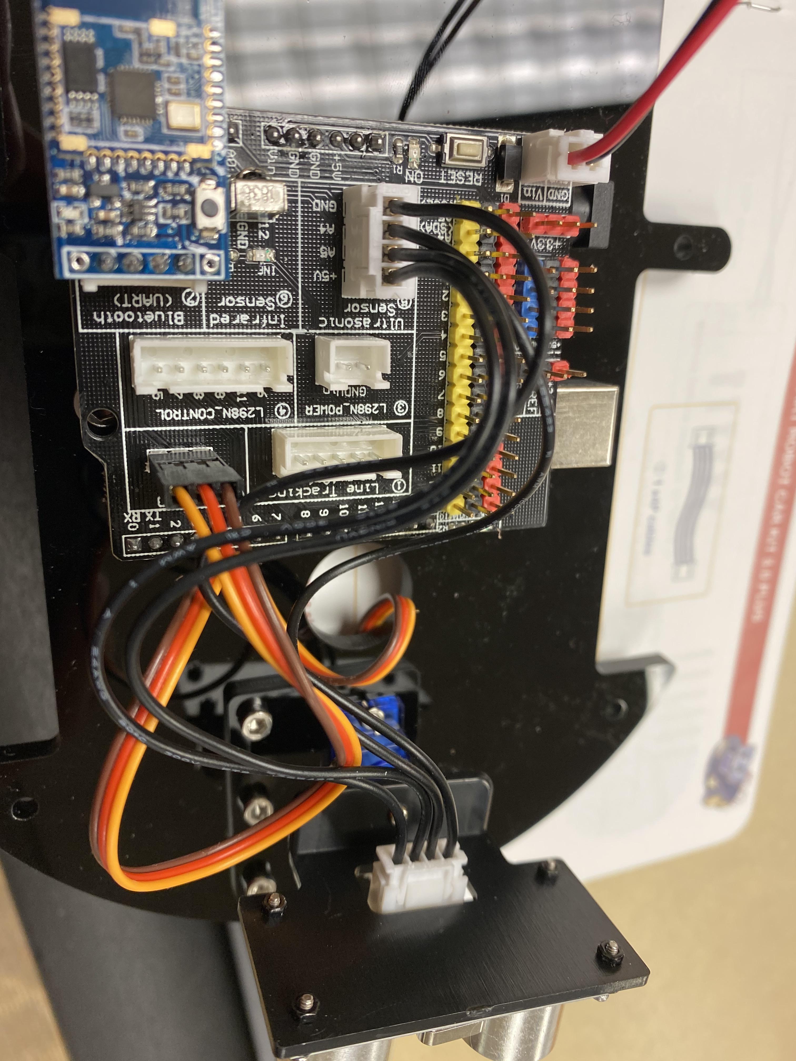
Now you need to connect the 4P cable to the back of the ultrasonic sensor and the other side needs to connect to the correct slot on the expansion board.
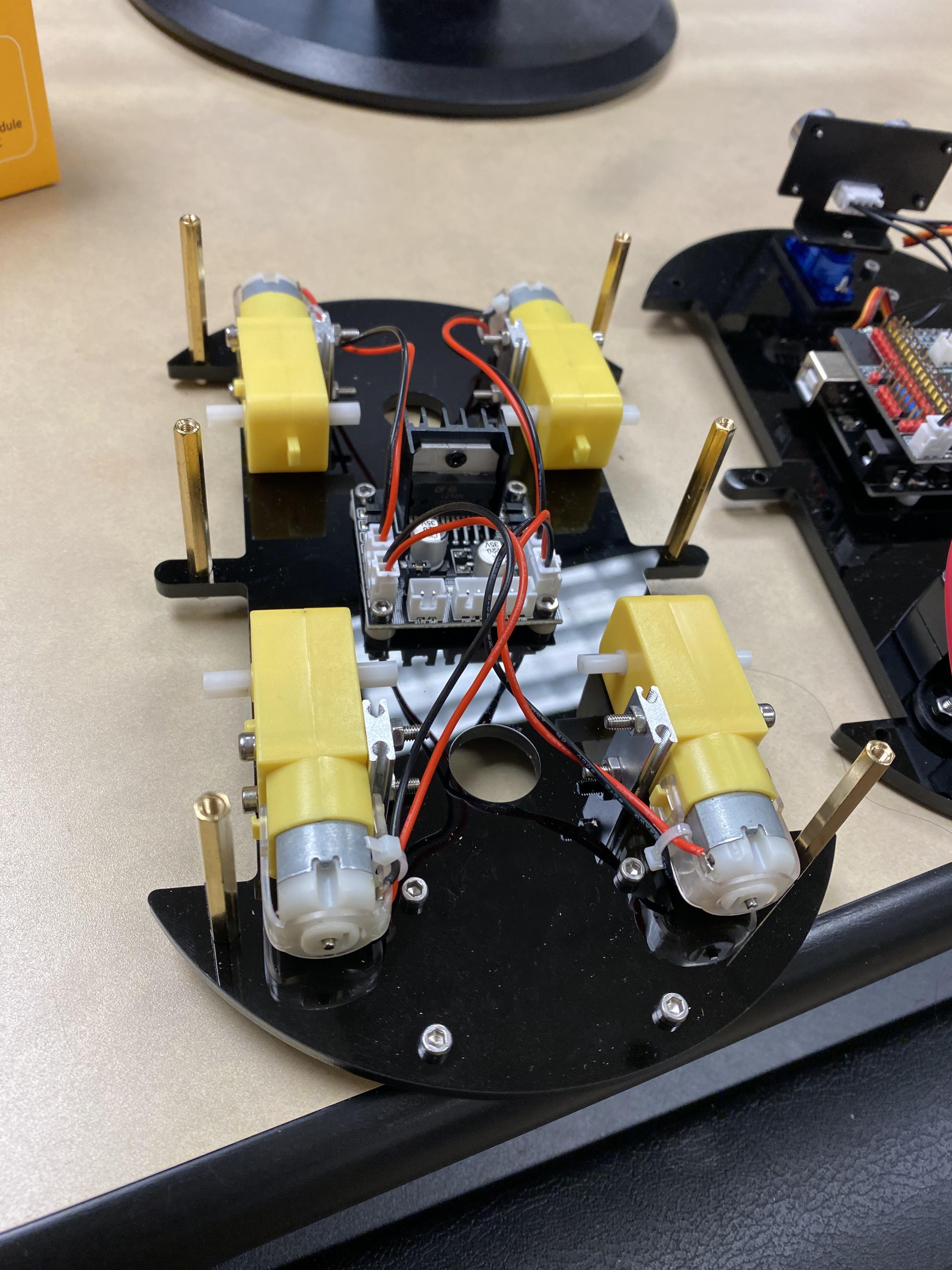
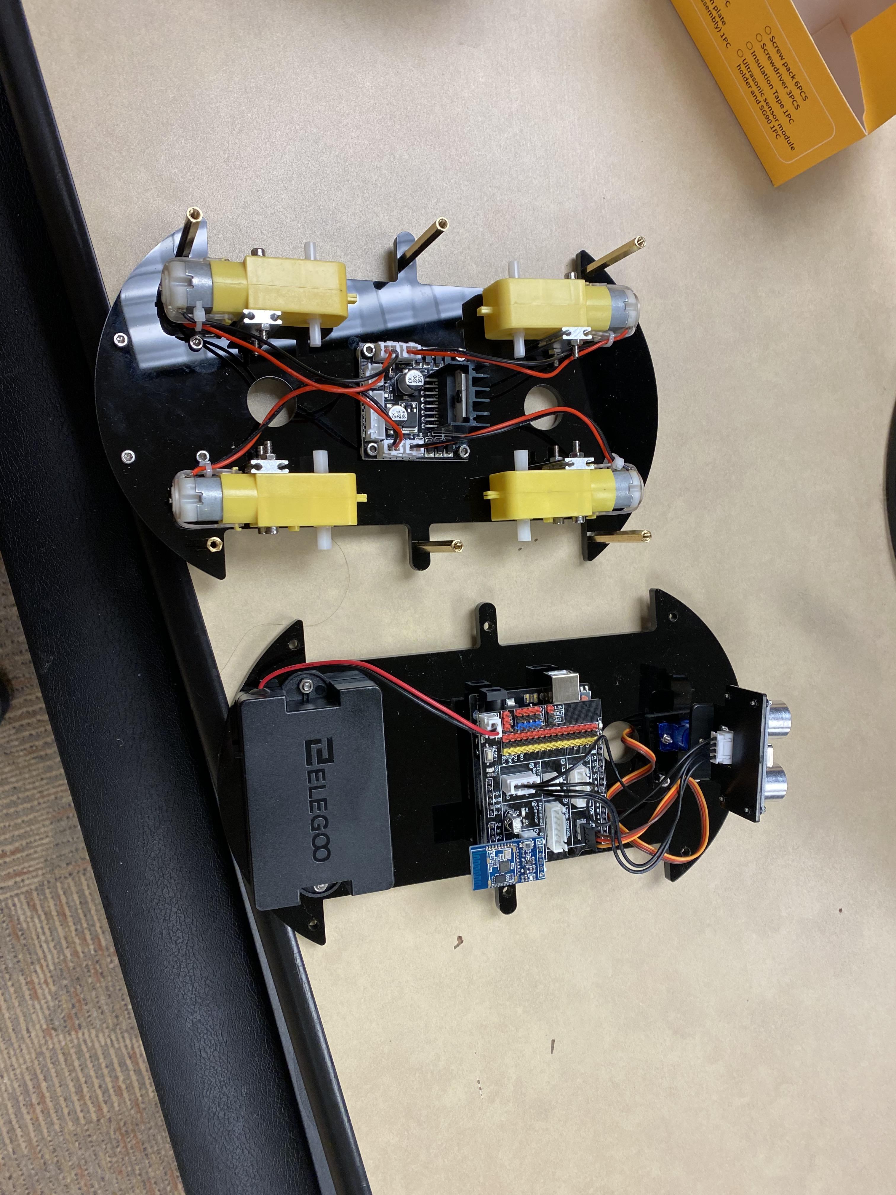
Next step is to screw in the double pass copper cylinder to the sockets with the hexagon socket screws.
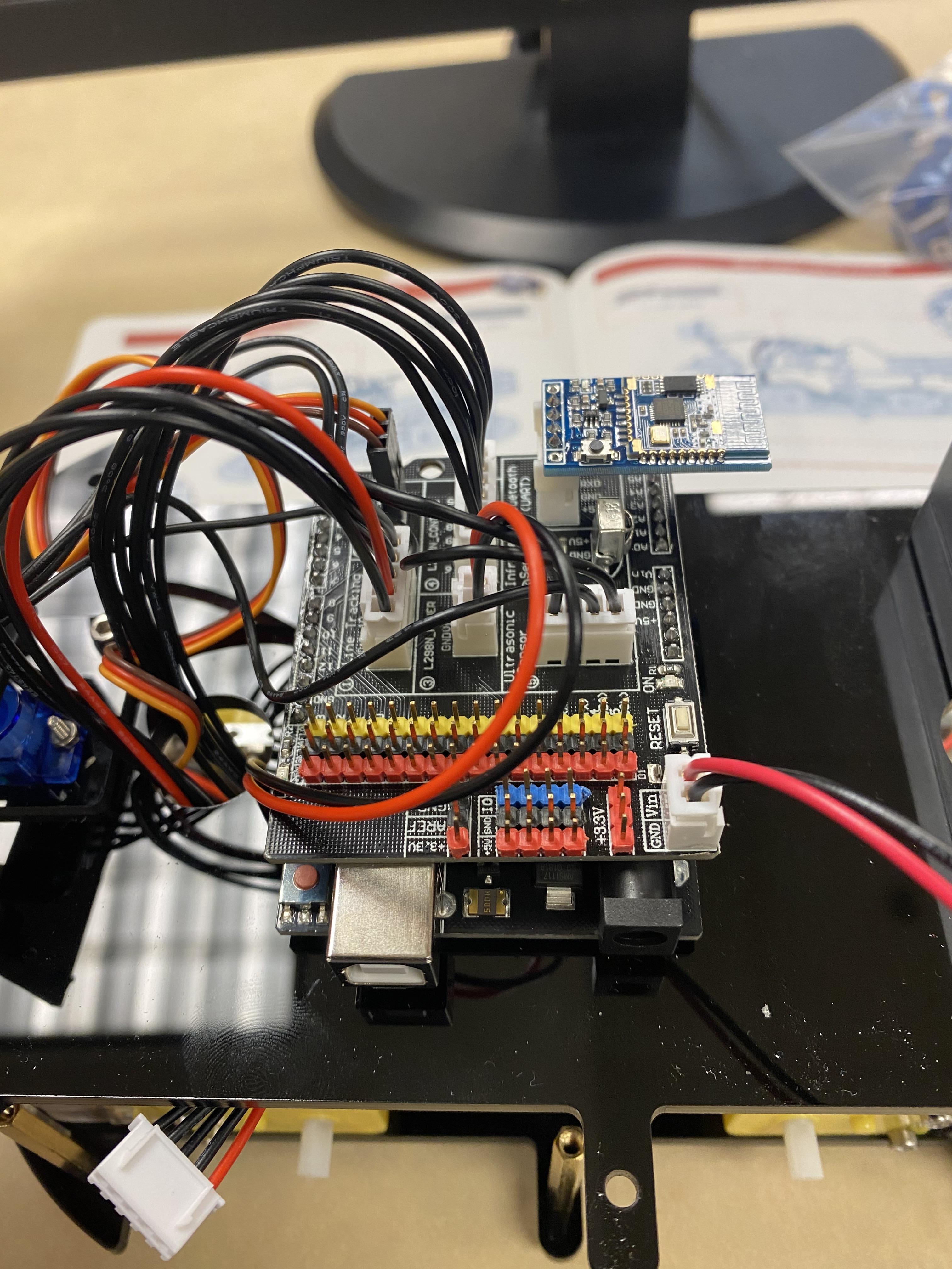
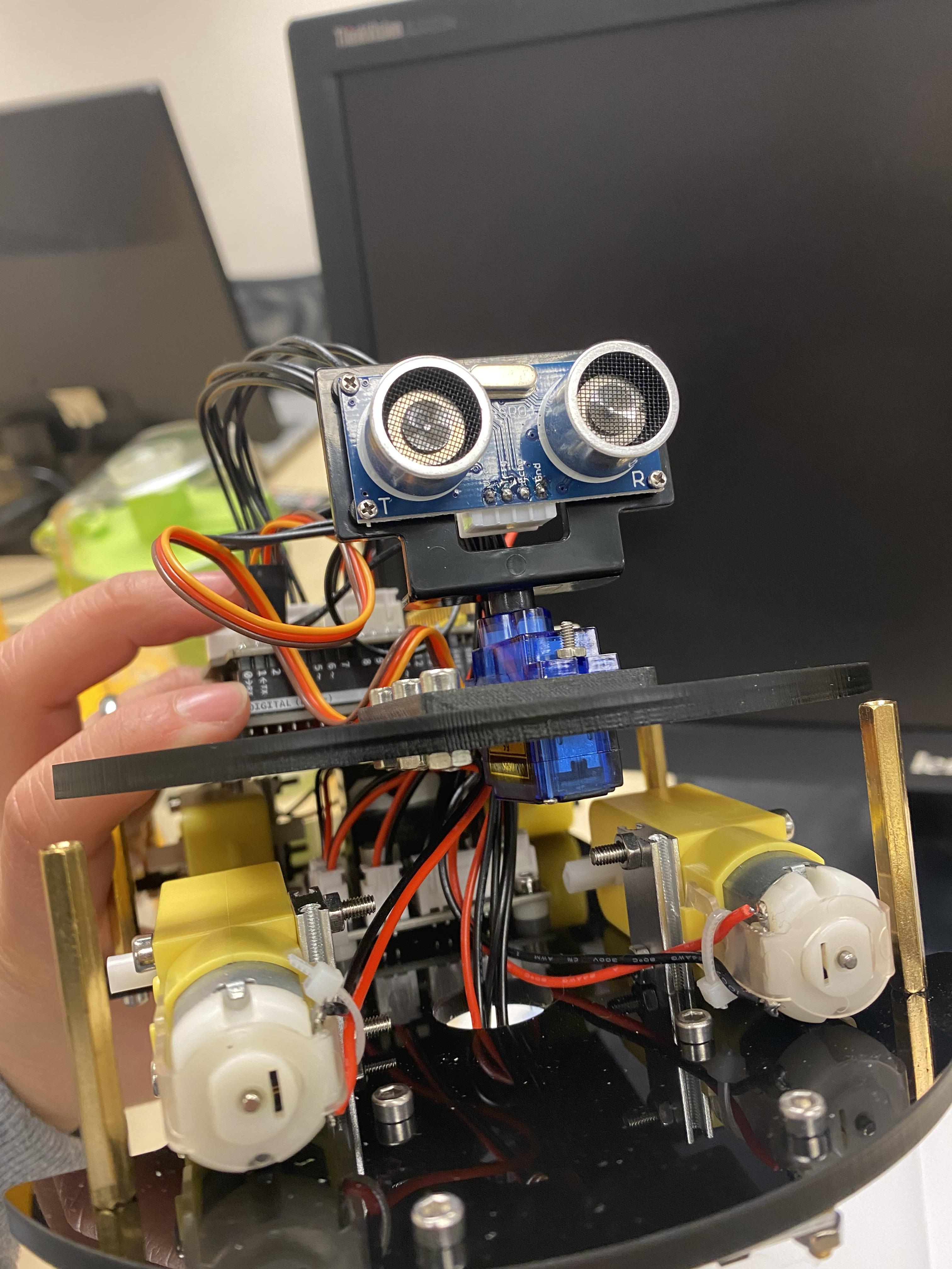
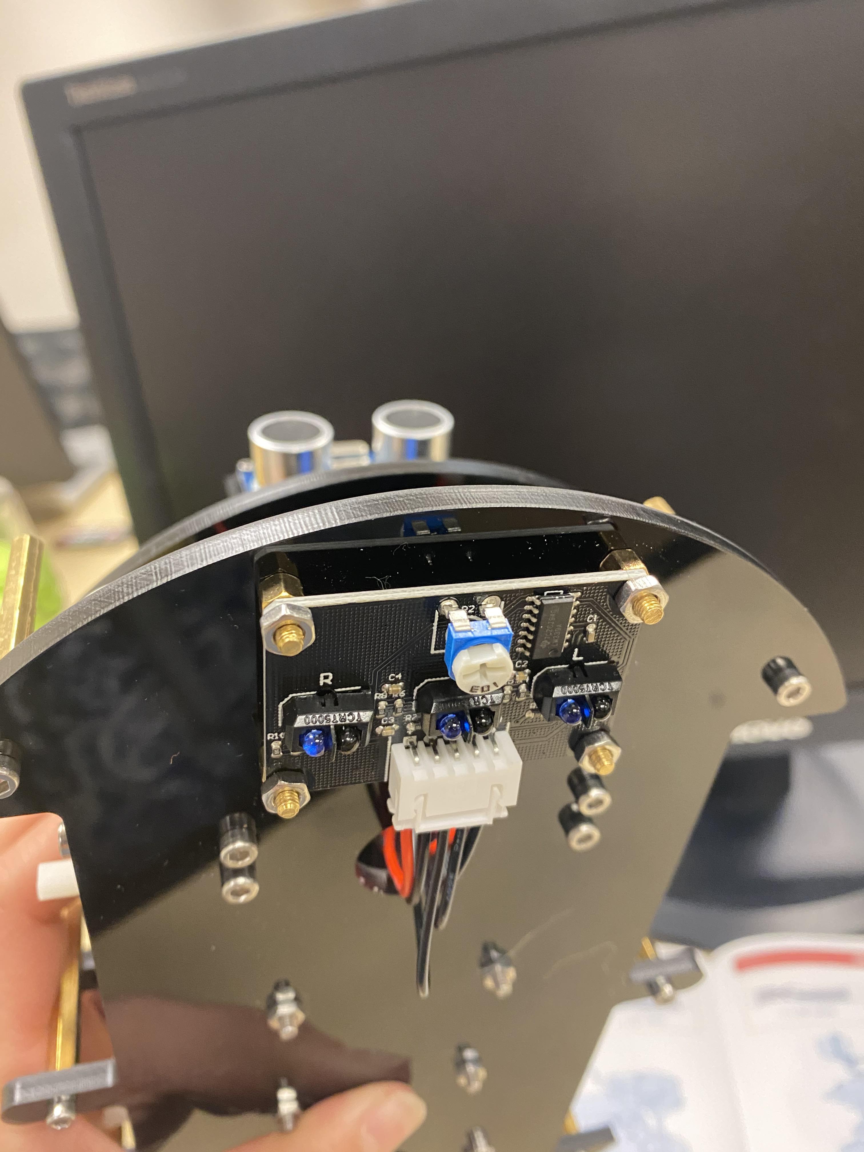
Next, we need to connect the 2P and 6P cable from the expansion board to the L298N. Your 5P cable needs to go from the expansion board to the line tracking module on the bottom of the car.
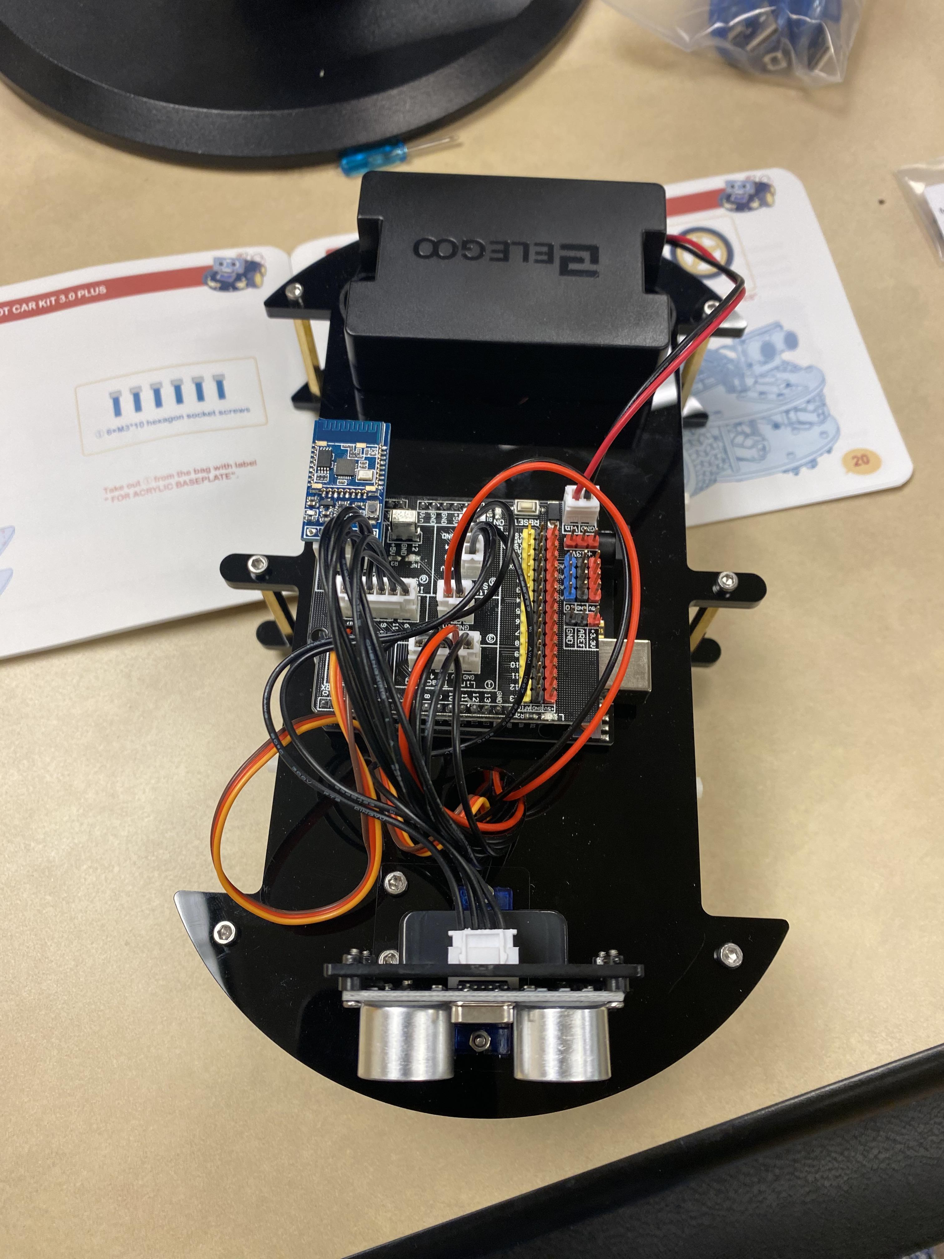
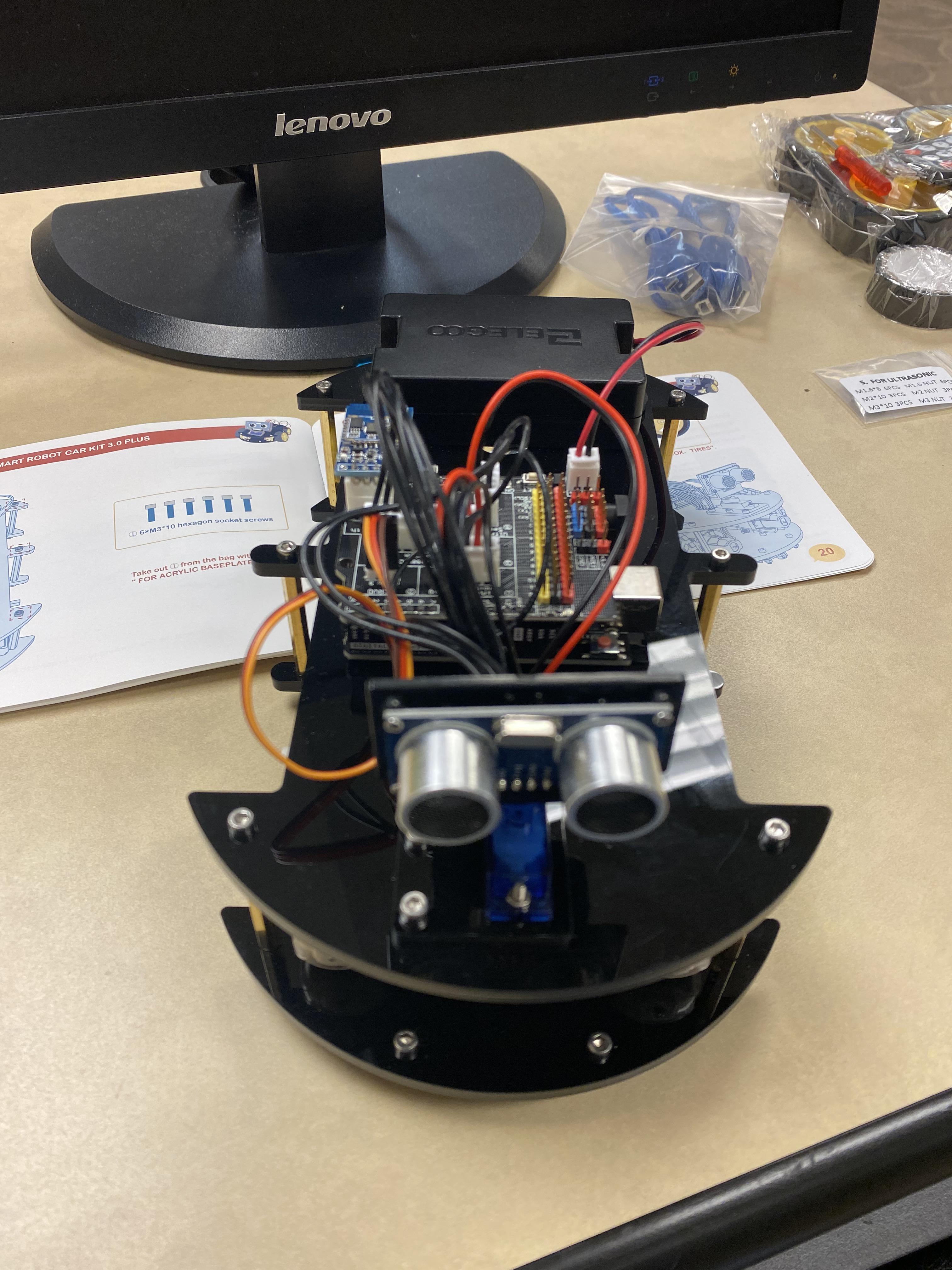
Now you can screw both layers on top of each other like so.
Adding the Wheels
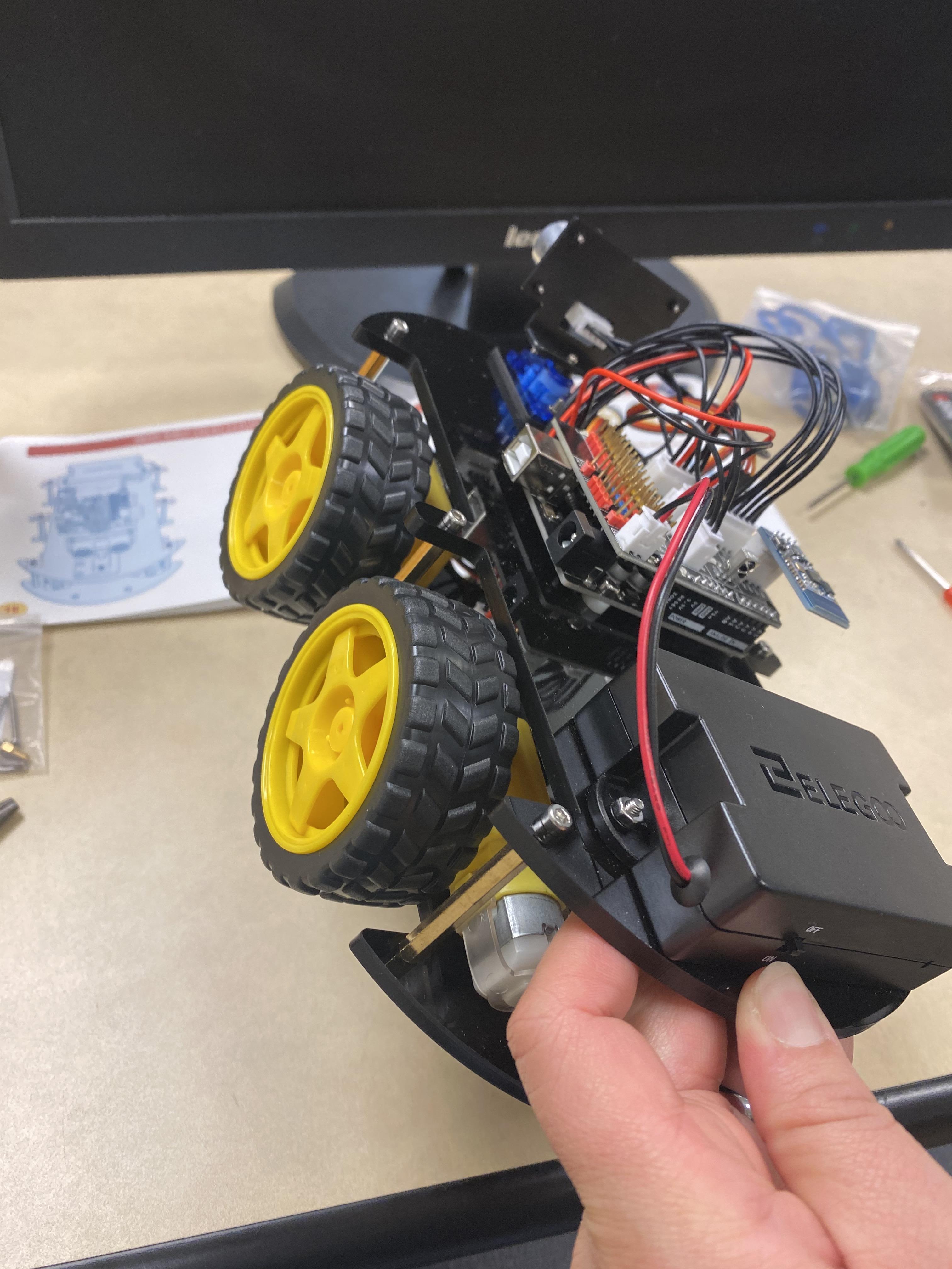
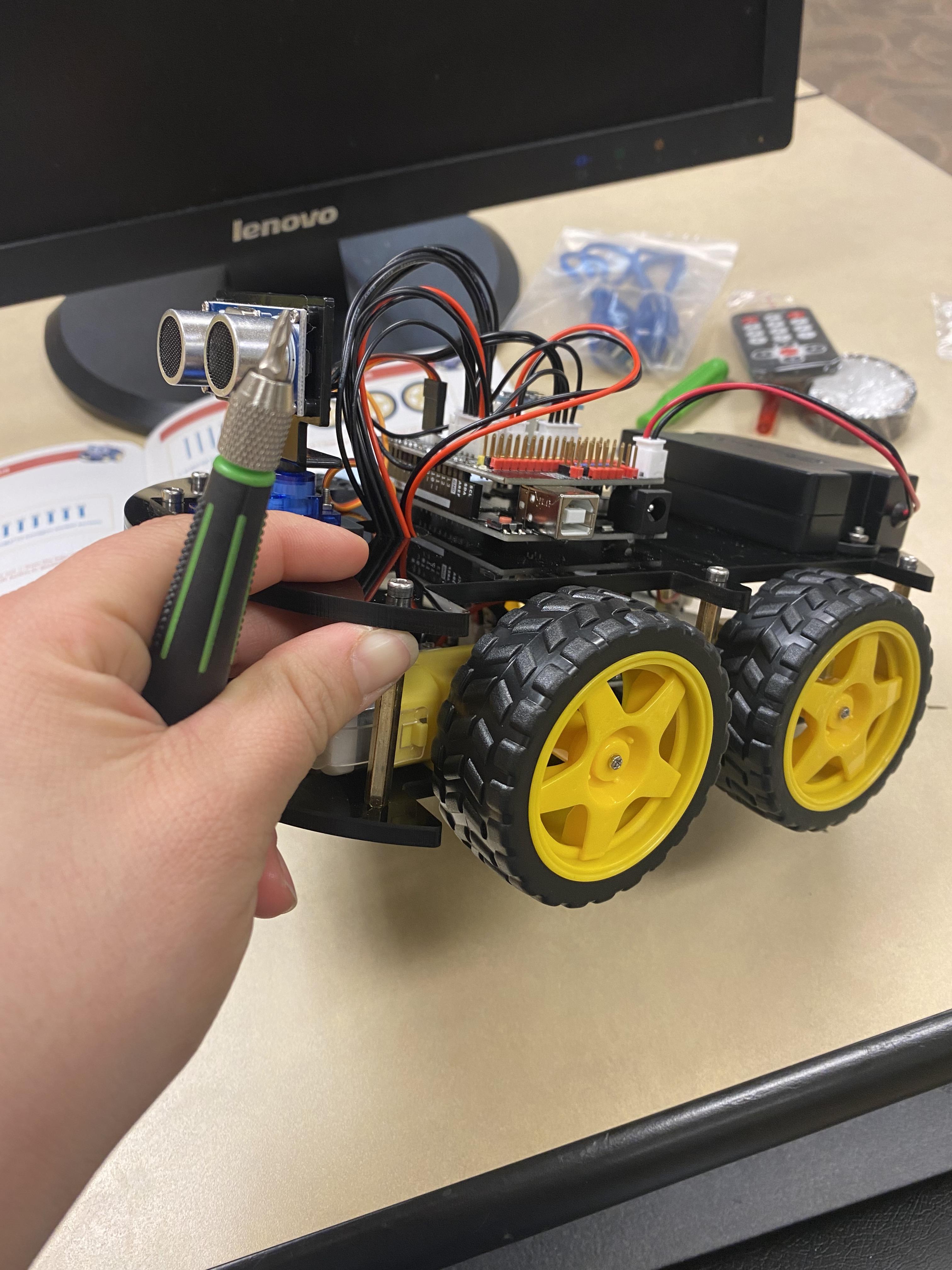
Now that the body of the bot is put together we can now install the wheels. Just attach the wheels to the DC motors and screw them in place.
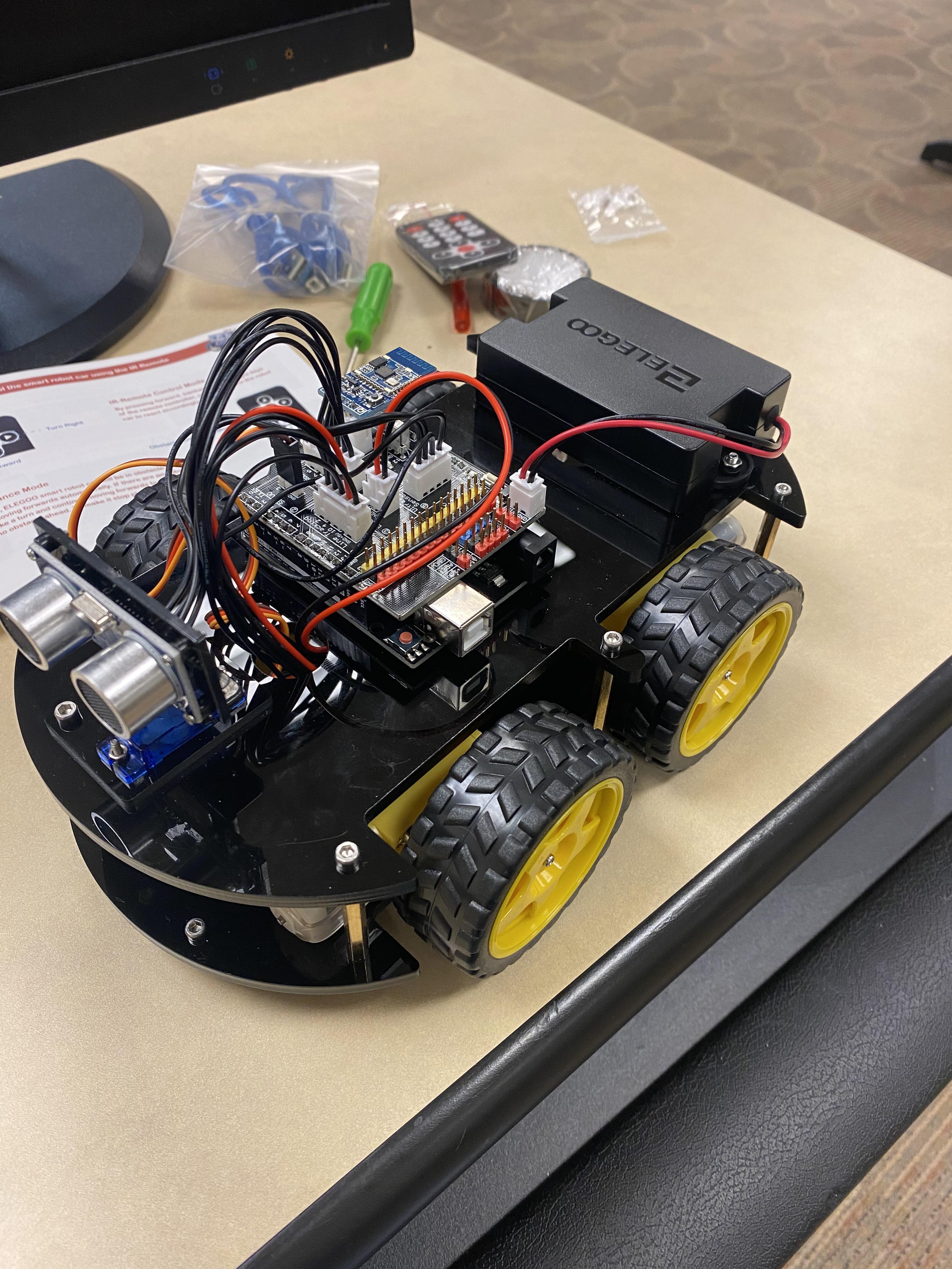
This should be your finished product.
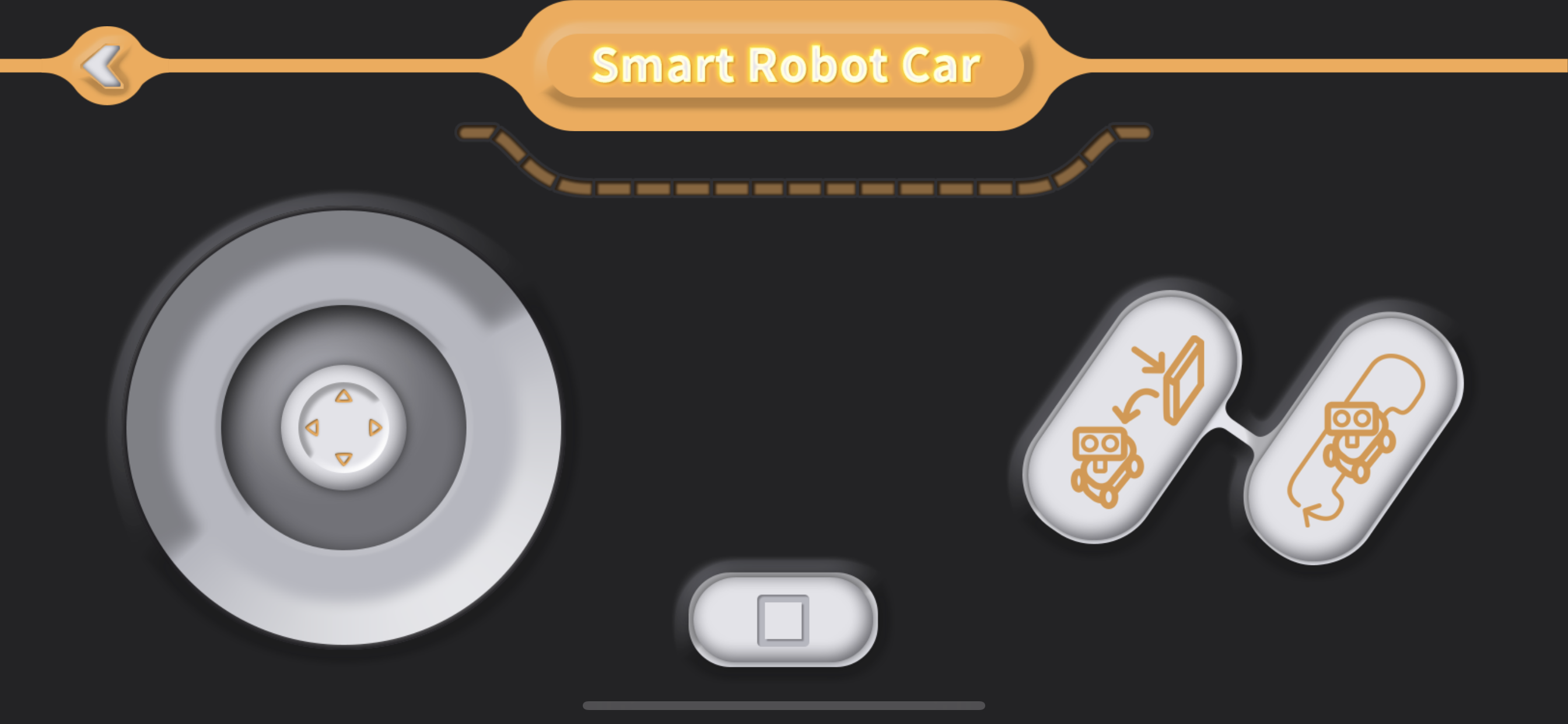
Now download the app called "Elegoo BLE Tool" connect to your car-bot and watch it go!