Smart Light Conversion Using ESP8266 and a Relay
by Arnov Sharma in Circuits > Electronics
7847 Views, 24 Favorites, 0 Comments
Smart Light Conversion Using ESP8266 and a Relay

.gif)
.gif)
.gif)

Hello everyone, and this is my "SMART LIGHT" setup, which can be controlled locally via any browser using a simple web app.
The idea behind this project was to combine a relay module and a Nodemcu board that I had lying around to convert one of my desk light panels into a proper smart light that a simple webpage could control.
I did the whole conversion process by using 3D printing and a few hacks, which I will be showing in this article, so let's get started.
Supplies
Following are the things I used in this built-
- 18W Slim Ceiling light Panel
- NodeMCU Board
- Relay Module
- AO3400 Mosfet
- 5V 500mA Charger
- 3D Printed Enclosure
- wire sleeve shrink wrap
Concept


So this light setup is similar to an actual AC smart light that I have examined in the past. They usually contain a relay module, or sometimes they have LED drivers that can be controlled by an enable pin. Because they are inexpensive, ESP-01 or bare ESP8266 chips are frequently used as microcontrollers.
Actual Design
.gif)


What I did in this project was take a relay module (not the whole module; I made a new compact module) and use the Nodemcu board for controlling the relay module. In addition, I added a 5V/500mA charger to power the Nodemcu and Relay Module.
Because the panel I was using was a slim 18W ceiling light, I needed to design an enclosure that would safely house all of the electronics while also acting as a holder or wall mount for adding the light to my shelf.
The design was simple: a box was modeled that had an opening in the middle, and the body had a rectangular part that holds the main LED driver circuit.
I did remove a few parts from the bottom side in order to reduce the material and print time.
Additionally, the box will feature a lid with an external portion for attaching a wall mount using an M6 bolt.
ESP8266 Relay Module Setup
.gif)

Before wiring anything on the main body, we first add the Nodemcu to a breadboard, connect a relay module to it and upload the below sketch that I wrote for a previous Home Automation project.
#include <ESP8266WiFi.h>

// Webserver Config
const char* ssid = "YOURSSID";
const char* password = "YOURPASS";

// Set web server port number to 80
WiFiServer server(80);

// Variable to store the HTTP request
String header;

// Auxiliar variables to store the current output state
String output1State = "off";


// Assign output variables to GPIO pins
const int output1 = 16; //D0


void setup() {
  Serial.begin(115200);
  // Initialize the output variables as outputs
  pinMode(output1, OUTPUT);


  // Set outputs to HIGH
  digitalWrite(output1, HIGH);


  // Connect to Wi-Fi network with SSID and password
  Serial.print("Connecting to ");
  Serial.println(ssid);
  WiFi.begin(ssid, password);
  while (WiFi.status() != WL_CONNECTED) {
    delay(500);
    Serial.print(".");
  }
  // Print local IP address and start web server
  Serial.println("");
  Serial.println("WiFi connected.");
  Serial.println("IP address: ");
  Serial.println(WiFi.localIP());
  server.begin();
}

void loop(){
  WiFiClient client = server.available();   // Listen for incoming clients

  if (client) {                             // If a new client connects,
    Serial.println("New Client.");          // print a message out in the serial port
    String currentLine = "";                // make a String to hold incoming data from the client
    while (client.connected()) {            // loop while the client's connected
      if (client.available()) {             // if there's bytes to read from the client,
        char c = client.read();             // read a byte, then
        Serial.write(c);                    // print it out the serial monitor
        header += c;
        if (c == '\n') {                    // if the byte is a newline character
          // if the current line is blank, you got two newline characters in a row.
          // that's the end of the client HTTP request, so send a response:
          if (currentLine.length() == 0) {
            // HTTP headers always start with a response code (e.g. HTTP/1.1 200 OK)
            // and a content-type so the client knows what's coming, then a blank line:
            client.println("HTTP/1.1 200 OK");
            client.println("Content-type:text/html");
            client.println("Connection: close");
            client.println();

            // turns the GPIOs on and off
            if (header.indexOf("GET /1/on") >= 0) {         //LOAD1
              Serial.println("LOAD1 on");
              output1State = "on";
              digitalWrite(output1, LOW);
            } else if (header.indexOf("GET /1/off") >= 0) {
              Serial.println("LOAD1 off");
              output1State = "off";
              digitalWrite(output1, HIGH);
            }


            // Display the HTML web page
            client.println("<!DOCTYPE html><html>");
            client.println("<head><meta name=\"viewport\" content=\"width=device-width, initial-scale=1\">");
            client.println("<link rel=\"icon\" href=\"data:,\">");
            client.println("<style>html { font-family: Helvetica; display: inline-block; margin: 0px auto; text-align: center;}");
            client.println(".button { background-color: #6a195b; border: none; color: white; padding: 16px 40px;");
            client.println("text-decoration: none; font-size: 30px; margin: 2px; cursor: pointer;}");
            client.println(".button2 {background-color: #a82890;}</style></head>");

            // Web Page Heading
            client.println("<body><h1>HOME AUTOMATION BASIC</h1>");

            // Display current state, and ON/OFF buttons for OUTPUT1
            client.println("<p>LOAD1 - State " + output1State + "</p>");

            // If the output1State is off, it displays the ON button
            if (output1State=="off") {
              client.println("<p><a href=\"/1/on\"><button class=\"button\">ON</button></a></p>");
            } else {
              client.println("<p><a href=\"/1/off\"><button class=\"button button2\">OFF</button></a></p>");
            }


            client.println("</body></html>");

            // The HTTP response ends with another blank line
            client.println();
            // Break out of the while loop
            break;
          } else { // if you got a newline, then clear currentLine
            currentLine = "";
          }
        } else if (c != '\r') {  // if you got anything else but a carriage return character,
          currentLine += c;      // add it to the end of the currentLine
        }
      }
    }
    // Clear the header variable
    header = "";
    // Close the connection
    client.stop();
    Serial.println("Client disconnected.");
    Serial.println("");
  }
}
The relay's 5V and GND are connected to the Nodemcu's VCC and GND pins, and the control pin of the relay is connected to D0 of the Nodemcu.
- After Uploading the Sketch, we open the serial monitor and wait for the ESP to get connected with the local WIFI network.
- you will see the Local IP Address when the ESP gets connected to the Network, copy this IP Address and open it in your browser.
- We can now toggle the Relay by pressing the button in the web app.
Power Source


As for the power source, I'm using a smartphone charger from 2012.
This one is rated for 5V and 500mA, which were the parameters most phones used back then.
I carefully removed the circuit from the plastic body by literally tearing the body with a plier. We will be using the main circuit as the power source for Relay and Nodemcu.
DIY Relay Module Setup
.gif)
.gif)
The size of this double relay setup is the worst thing about it, even though relay modules are quite useful for controlling a variety of AC equipment.
You could counter that using a single relay module is preferable because it provides appropriate isolation and switches the relay using an optocoupler, making the entire configuration much safer. Yes, that is a valid point, but since I lack either a single relay module or an optocoupler, I will use a straightforward single relay module for this iteration, which will be switched ON and OFF by a straightforward Mosfet configuration.
For the mosfet, I'm using the AO3400, and it's an N-channel mosfet.
Testing the Relay Module
.gif)
After building the relay module, I attached it using Nodemcu and toggled the relay using the same website sketch.
I connected a multimeter to the relay's NO and Common Terminals, then I set the multimeter to continuity mode. The LED glows and the relay status changes from LOW to HIGH when the D0 Pin is toggled, as observed on the multimeter.
Next, we work on the isolation part of the electronics.
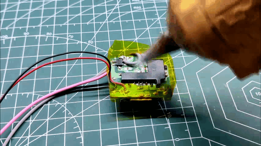
Potting Process Relay Module
.gif)
.gif)

The module we created will operate without a hitch. however, using an AC supply still carries a serious electric threat.
In order to properly encapsulate the board, we must first isolate it from the bottom side. To do this, we employ the potting process, which is a phrase used in electronics for filling or embedding the components by poring a resin or other similar hardening material.
Normally, two-part epoxy is used in this method, but since I didn't have any, I just used hot glue.
Potting Process Charger Circuit
.gif)
.gif)
.gif)
.gif)
We use the same potting procedure for the charger circuit; the only difference is that we pot on both sides to create a solid piece of hotglue that keeps the circuit in place like patties in burgers.
Testing the Charger Circuit

We quickly test the setup after the potting process to see if it still functions, and the good news is that it did.
Then, we get the 3D-printed components ready.
3D Printing Process
.gif)


I exported the mesh files of each part and then printed them on my Ender 3 with PLA using the settings listed below.
3D Printing parameters
- Layer Height - 0.2mm
- Nozzle - 0.4mm
- Infill- 10%
- Infill- cubic
LID Assembly

.gif)
Using two M2 screws, we attach the rectangular component with the cover before the main assembly. Because we need to print the entire lid, which will provide support material to the bottom side, this rectangular section was taken out of the lid and inserted as an external part to speed up printing.
I eliminated the rectangular portion and printed the lid inverted because support materials require more waste material and time (top side on bottom).
This saved time and material.
Wiring Diagram


Following are the two wiring diagrams that were used in the construction of this lighting setup.
Assembly
.gif)
.gif)
.gif)
.gif)
.gif)
.gif)
- Using super glue, we first attach the base body to the bottom side of the light panel. Here, super glue is used, and we use a lot of it to make things a little more permanent.
- Following the wiring diagram, we add components to the Base body and then connect them all. Each wire connection also receives a shrink sleeve so that it can later be covered.
- We then use a cigarette lighter to heat the sleeves in order to shrink them after checking all of the connections (AC Connections) once more.
- Next, we add Relay Module's terminals with Nodemcu and then add nodemcu in its place.
- We apply some hot glue to keep things in place.
- Eight M2 Screws, two for each side, are then used to attach the Lid to the base body.
Adding the Light Setup to Wall Shelf
.gif)
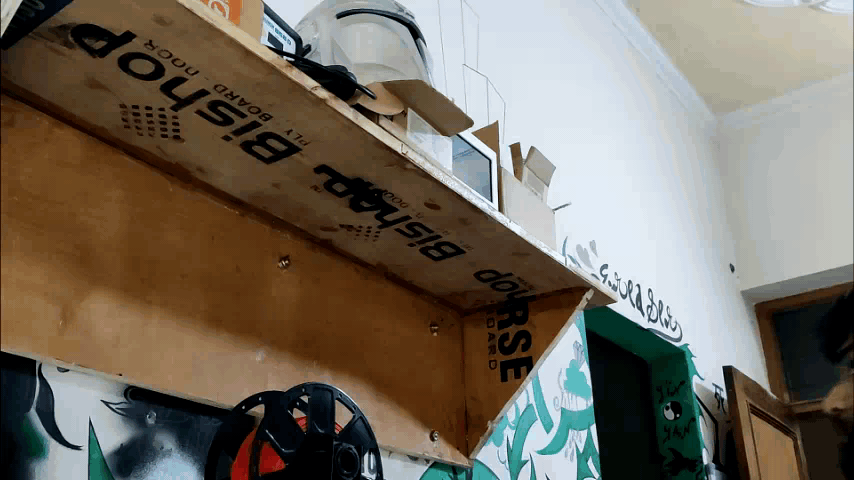.gif)

.gif)
The wooden shelf is then fastened to the wall mount component with an M3 screw. The M3 screw, when inserted directly into the wood, will create its own mounting hole when pressure is applied.
The Switch is then turned ON after inserting the power cord into the AC socket.
The light will remain ON when we power everything up because we added the light AC Pins to the relay's NC and COM terminals. This functionality can be modified in the code, but I decided to keep it so that I could use the light as a standard light that could be switched ON and OFF with a conventional switch. The smart part could then be controlled using a web app.
RESULT

.gif)
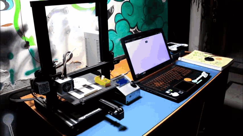.gif)
.gif)
.gif)
.gif)
.gif)
The end result is a light that can be controlled by a web application.
This conversion project was successful, and we can carry out a process similar to it on a variety of items. To get started, all you need to do is add a relay and an ESP to any AC device that has a separate 5V power source.
I'm working on the second iteration of this setup that will include a charger circuit into a compact board that will house the entire relay and nodemcu system.
Leave a comment if this project was useful or helpful.
That's all for now, folks. I'll be back soon with a new project.
Peace