Smart Home Solution

Elevate your home automation with our Smart Touch Panel. Control devices with Alexa, Google, touch, an IR remote, and your smartphone.
What is Home Automation?
Home automation, also known as smart home technology, is the automation of a home's various features and functions, such as lighting, climate, entertainment systems, and appliances. It can also include advanced home security features like access control and alarm systems. With the integration of Internet connectivity, these devices form an essential part of the Internet of Things. Enjoy the convenience and energy savings that come with a smarter home, by investing in a home automation system today.
Project Aim:
A smart module that enables seamless control of your home electronics appliances with a variety of methods, including your smartphone, touch control, IR remote, and voice assistants such as Alexa and Google. Our cutting-edge technology, powered by the advanced CYPRESS chip, allows you to achieve a smarter home experience that caters to your needs and preferences. Say goodbye to the hassle of controlling your home appliances and embrace the convenience and ease of our Smart Module. Upgrade your home today and enjoy the benefits of this game-changing technology.
Supplies
Basic components:
- 5v Relay: This switch controls the circuit electromechanically, allowing electrical appliances to be turned on and off with a low-power signal.
- Diode: This is used to prevent PSOC.
- Optocoupler IC (moc3063): A current is applied to the Optocoupler, which emits light proportional to the current. The light then switches on the photosensitive device, which conducts a current like an ordinary transistor.
- Triac (BT136-600v-4a-triac): Triacs are electronic components that can switch high voltages and high levels of current over both parts of an AC waveform. They are ideal for a variety of power-switching applications.
- Metallized Polyester Fan Regulator Capacitors: Capacitors are used to control fan speed.
Hardware components:
- Infineon CY8CKIT-041-41XX PSoC™ 4100S CapSense Pioneer Kit
- CY8C4245-AXI 483
- Espressif ESP8266 ESP-12E
- 5V Relay PCB Mount (PCB designs Provided)
- IR receiver (generic)
Software apps and online services
- Cypress PSoC Creator
- Arduino IDE
- Microsoft VS Code
Hand tools and fabrication machines
- Tweezers, SMD Soldering/Desoldering
- Solder Wire, Lead-Free
- Solder Paste, Rework
- Solder Flux, Soldering
- PCB Holder, Soldering Iron
Connections
1. Controlling Electronics appliances :

2. Controlling Fan Speed

Schematic Diagram:
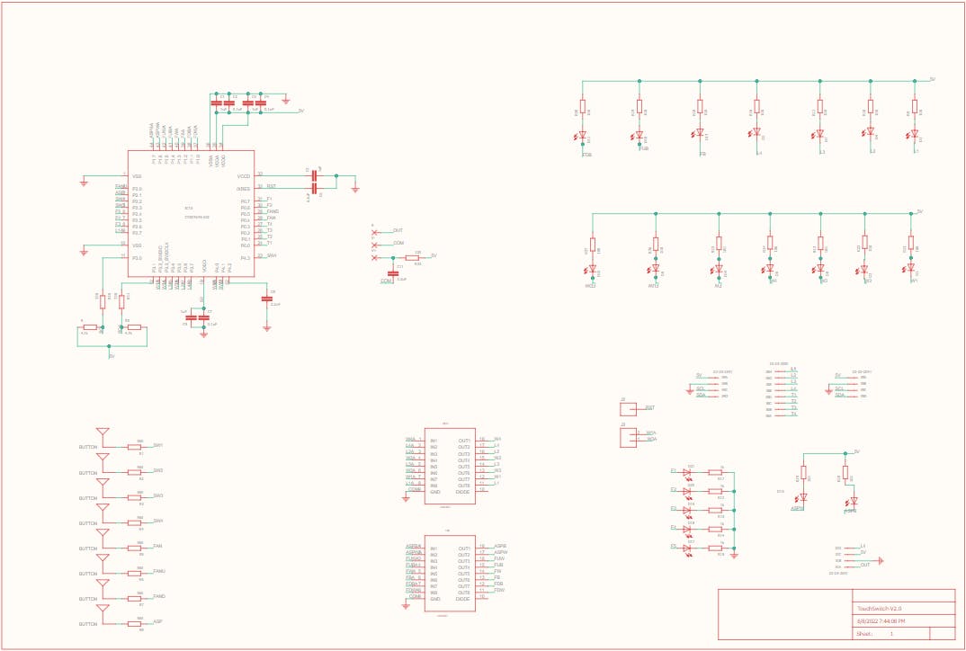
To demonstrate the functionality of our system, we have started with 4 light controls and 1 fan control. Please refer to the schematic diagram of the power module below for a visual representation of our setup.

Please find the schematic diagram of our Touch Module below. This diagram outlines the functionality and components of our system, which allows for seamless control of home electronics appliances through touch control, IR remote, and voice assistants such as Alexa and Google.
PCB Viewer:
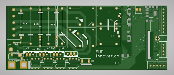
Please find attached the Power Module View for our system. This module is a crucial component of our technology, allowing for efficient and reliable power management for the various home electronics appliances being controlled.
Gerber File:https://drive.google.com/file/d/1jbXJZqadmYrhs8SUUFjje20PhvFAiVj-/view?usp=share_link
Front side:
Back side:

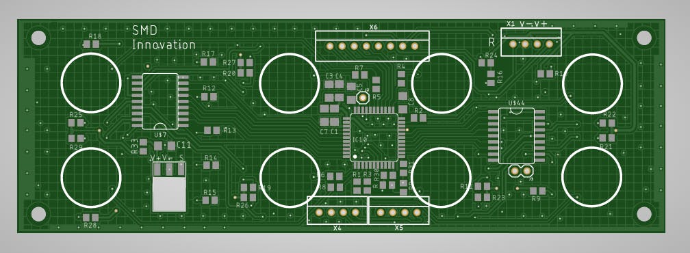
Please find attached the Touch Module View for our system. This module serves as the interface between the user and the home electronics appliances being controlled. With touch control, IR remote, and voice assistant capabilities, our Touch Module offers a variety of ways to seamlessly control your smart home devices.
Front side:

Back side:
Gerber File: https://drive.google.com/file/d/1ap_wFNBFkqszh2POsxibOfh2cUS4051q/view?usp=share_link
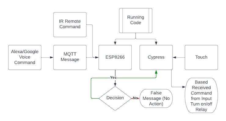
Our module code is designed to handle all user operations to control home electronics appliances using our smart home automation system. The system offers four modes of operation:
- Touch: The Cypress capacitive touch technology senses user touch input and reacts based on the last state of the relay value.
- Voice Command: Alexa publishes MQTT messages, which our ESP module subscribes to receive. I2C communication is used between the Cypress chip and the ESP8266 to enable voice command operation.
- IR Remote: Our ESP8266 decodes user input button commands and sends them to the Cypress chip using I2C communication. The Cypress chip reacts based on the input command.
- Smartphone: The user's smartphone can publish MQTT messages, which our ESP module subscribes to receive. I2C communication is used between the Cypress chip and the ESP8266. Based on the received command, the Cypress chip reacts and handles the relay.
Our module code allows for seamless integration of these four modes, offering users flexibility and convenience in controlling their home electronics appliances.
Flow Chart of Working System
MQTT topic and message description :
Kit have two Capsense button. I used that as two switches.
Capsense 1 --> Topic : cap1 --> Message : TURNON/TURNOFF
Capsense 2 --> Topic : cap2 --> Message : TURNON/TURNOFF
CypressCode
1. To import C libraries in your code, you need to include their header files using the #include preprocessor directive. This allows you to use functions and data types from the library in your program.
#include "project.h"
#include "stdlib.h"
#include "cyapicallbacks.h"
2. The code snippet you provided consists of four C function prototypes. These are:
void updateLoad(void);
void loadWrite(uint8,uint8);
void HandleError(void);
void i2cReceive(void);
- void updateLoad(void): A function that updates the load status of a device.
- void loadWrite(uint8, uint8): A function that writes a value to a specific load.
- void HandleError(void): A function that handles errors that may occur during program execution.
- void i2cReceive(void): A function that receives data via the I2C communication protocol.
These function prototypes define the function name, return type, and parameters (if any) that the function accepts. They are often used as a way to declare functions before they are implemented or used in a program, helping to ensure that the function is properly defined and its usage is correct.
3. The code snippet you provided defines two preprocessor directives using the #define keyword.
#define LightloadNumber 4
#define FanLoadNumber 1
- #define LightloadNumber 4 defines a preprocessor macro with the name LightloadNumber and a value of 4. This macro can be used in the code to represent the number of light loads that can be controlled by the program.
- #define FanLoadNumber 1 defines a preprocessor macro with the name FanLoadNumber and a value of 1. This macro can be used in the code to represent the number of fan loads that can be controlled by the program.
These preprocessor directives help to make the code more readable and maintainable by defining values that are used in multiple places throughout the program in one central location. Anytime the program needs to refer to the number of light or fan loads, it can use these macros instead of hardcoding the values, which makes the code more flexible and easier to modify in the future.
4. These lines are declaring and initializing various arrays and variables that will be used in the program for controlling the smart home automation system.
uint8 state_switch[LightloadNumber];       //status of touch switch
uint8 pre_switch[LightloadNumber];         //previous status of touch switch
uint8 state_load[LightloadNumber];         //status of load
uint8 state[LightloadNumber + FanLoadNumber + 1];   //state for communication
uint8 pre_state[LightloadNumber + FanLoadNumber + 1];   //state for communication
uint8 state_Fswitch[FanLoadNumber];   //status of fan switch
uint8 pre_Fswitch[FanLoadNumber];    //previous status of fan switch
uint8 fan_state[2];
uint8 state_Fan[FanLoadNumber];    //status of fan regulator

uint8 Switch[] = {0,1,2,3};   // touch swich for light load(cap sense button 0,1,2,3)
uint8 Load[] = {0,1,2,3};  //load connection for switch (L0,L1,L2,L3)(relay)
uint8 F_UP_DWN[2] = {5,4}; //fan up and down touch switch(cap sense button 5,6)
uint8 Fan[4] = {7,6,5,4};  //fan output connection(L4,L5,L6,L7)
uint8 Fan_led[5] = {12,11,10,9,8}; // fan speed indicator led(L8,L9,L10,L11,L12)
uint8 white_led_load[] = {13,14,15,16}; //white led for each load(L13,L14,L15,L16)
uint8 Fan_UDW[2] = {18,17};  //fan up down white led
uint8 Fan_UDB[2] = {22,21};  //fan up down blue led

// smd button down
/*
uint8 F_switch[] = {6}; //fan touch switch (cap sense button 4)
uint8 Fan_BW[2] = {20,19};   //fan blue and white led
uint8 Scenebut = {7};  //touch switch for smd pad(cap sense button 7)
uint8 scene_BW[2] = {23,24};  //smd switch up down blue led
*/
// smd button up
uint8 F_switch[] = {7}; //fan touch switch (cap sense button 4)
uint8 Fan_BW[2] = {24,23};   //fan blue and white led
uint8 Scenebut = {6};  //touch switch for smd pad(cap sense button 7)
uint8 scene_BW[2] = {19,20};  //smd switch up down blue led

uint8 ScenebutStatus = 0;
uint8 pre_ScenebutStatus = 0;
uint8 whiteLed = 1;      //status of activation of white led of all loads

//i2c
uint8 i2cReadBuffer[(LightloadNumber + FanLoadNumber + 1)];
uint8 i2cWriteBuffer[(LightloadNumber + FanLoadNumber + 1)];
uint8 I2CFlag = 0u;

uint8 sceneled = 0;
uint8 speed = 0;
int onOffFlag = 0;

uint8 flag = 0;
- The arrays state_switch, pre_switch, state_load, and state_Fswitch are used to keep track of the current and previous status of the touch switches and fan switch.
- The array state and pre_state are used for communication between the modules.
- The arrays Switch, Load, F_UP_DWN, Fan, Fan_led, white_led_load, Fan_UDW, and Fan_UDB are used to define the connections for the touch switches, loads, fan, fan speed indicator led, white led for each load, fan up down white led, and fan up down blue led respectively.
- The variable ScenebutStatus keeps track of the status of the touch switch for the smd pad.
- The arrays i2cReadBuffer and i2cWriteBuffer are used for communication over I2C.
- The variables scene led, speed, onOffFlag, and flag are used for controlling the system.
5. A callback function:
void I2C_I2C_ISR_ExitCallback()
{
    I2CFlag = 1;
}
A callback function that is executed when the I2C (Inter-Integrated Circuit) module finishes sending or receiving data. Specifically, it is called when the I2C interrupt is triggered and signals that the I2C communication has completed.
In this particular code, the function sets a flag variable called I2CFlag to 1, indicating that the I2C communication has finished. This flag can be used by other parts of the code to determine when to take further action based on the results of the I2C communication.
6. The code that controls loads (lights and fans) using CapSense touch sensors and an I2C interface.
int main(void)
{
    memset(state_switch,0,sizeof(state_switch));
    memset(pre_switch,0,sizeof(pre_switch));
    memset(state,0,sizeof(state));
    memset(state_load,0,sizeof(state_load));
    memset(pre_state,0,sizeof(pre_state));
    memset(state_Fswitch,0,sizeof(state_Fswitch));
    memset(pre_Fswitch,0,sizeof(pre_Fswitch));
    memset(fan_state,0,sizeof(fan_state));
    memset(i2cReadBuffer,0,sizeof(i2cReadBuffer));

Continue... in int_main.txt file.
The program initializes the various memory locations to zero and sets the state of the loads to zero. It then initializes and enables the Watchdog Timer, CapSense module, and I2C interface.
In the main loop, the program scans all enabled sensors and checks the status of the Scene button. If the Scene button is pressed, the program turns on/off all the loads depending on their previous state. If all loads are on, the program turns on the "All off" button and turns off the "All on" button, and vice versa.
The program then checks the status of the touch sensors for each load and sets the state of the loads accordingly. It also checks the status of the Fan switch and sets the state of the Fan load accordingly. If the white LED is on, the program sets the state of the white LED load accordingly.
The program also sets the various memory locations to their respective values in order to ensure proper functioning. The program then repeats this loop continuously.
7. This is a function that receives data over I2C communication and updates the states of various loads connected to the microcontroller accordingly.
void i2cReceive(void){
    for (uint8 i = 0; i < LightloadNumber; i++) {
        state[i] = i2cWriteBuffer[i];
        if (state[i] == 0) {
            loadWrite(Load[i],0);
            if(whiteLed == 1)
                loadWrite(white_led_load[i],1);
        }
        else if (state[i] == 1) {
            loadWrite(Load[i], 1);
            loadWrite(white_led_load[i],0);
        }
    }
Continue... in i2cReceve.txt file.
The function starts by iterating through a for loop that goes up to a value defined by the macro LightloadNumber. For each iteration, the state of a particular load is updated with the corresponding value received over I2C communication. If the state is zero, the corresponding load is turned off, and if the whiteLed variable is set to one, the white LED load is turned on. If the state is one, the corresponding load is turned on, and the white LED load is turned off.
After the loop, the state of the Fan load is updated based on the value received over I2C communication at index 4 of the i2cWriteBuffer array. If this value is zero, then the Fan load is turned on, and if it is one, the Fan load is turned off. The state of the Fan is then used to set the state of two other loads (Fan_BW[0] and Fan_BW[1]) using bitwise NOT and bitwise AND operations.
Finally, the speed of the Fan load is updated based on the value received over I2C communication at index 5 of the i2cWriteBuffer array. Depending on the value of the speed, different combinations of loads (Fan[0] to Fan[3]) are turned on or off.
8. Function loadWrite
void loadWrite(uint8 loadpin,uint8 state){
    switch(loadpin){
        case 0:
            L0_Write(state);
            break;
        case 1:
            L1_Write(state);
            break;
Continue... in loadWrite.txt file.
This function loadWrite is used to write a digital state (high or low) to a specific load pin. The function takes two arguments: the first argument loadpin is an integer that specifies the load pin number (ranging from 0 to 24), and the second argument state is an integer that specifies the state of the load pin (0 or 1, low or high).
The function uses a switch-case statement to determine which load pin to write to based on the value of loadpin. Each case corresponds to a specific load pin number and calls the appropriate function (e.g. L0_Write, L1_Write, etc.) to write the specified state to that load pin.
9. Function HandleError
void HandleError(void)
{

     /* Disable all interrupts. */
    __disable_irq();

    /* Infinite loop. */
    while(1u) {}
}
The HandleError() function is used to handle errors in the firmware. It disables all interrupts and enters an infinite loop, effectively stopping the execution of the program. This function is typically called when a serious error is detected that cannot be recovered from, such as a hardware fault or a critical software error. By entering an infinite loop, the program is effectively halted, preventing any further damage or malfunction from occurring. This function is commonly used in safety-critical systems where the failure of the system could result in harm to people or damage to property.
Arduino Code
1. Header Files:
#include <Wire.h>
#ifndef UNIT_TEST
#include <Arduino.h>
#endif
#include <IRremoteESP8266.h>
#include <IRrecv.h>
#include <IRutils.h>
This is a header file for an Arduino sketch that includes libraries for working with infrared (IR) remote control signals. Specifically, it includes the following libraries:
- Wire.h: This library provides support for the I2C communication protocol used to communicate between microcontrollers and other devices in a network.
- Arduino.h: This library provides definitions for the basic data types and constants used in the Arduino language, and includes the setup() and loop() functions that are necessary in every Arduino sketch.
- IRremoteESP8266.h: This library provides support for receiving and decoding IR remote control signals using an IR receiver module connected to the ESP8266 microcontroller.
- IRrecv.h: This library provides an interface for receiving IR remote control signals using the IR receiver module.
- IRutils.h: This library provides utilities for working with IR remote control signals, including decoding and encoding functions.
2. Define Variables:
#define CAPTURE_BUFFER_SIZE 1024
#define TIMEOUT 15U

uint16_t RECV_PIN = 14;
IRrecv irrecv(RECV_PIN, CAPTURE_BUFFER_SIZE, TIMEOUT, true);
decode_results results;  // Somewhere to store the results

int sCount = 6;
int data[6] = {0, 0, 0, 0, 0, 0};
byte i2cadd = 8;
String t = "";

unsigned long delay1 = 0;
This code defines several variables and constants:
- CAPTURE_BUFFER_SIZE is set to 1024, which is the size of the buffer used to store the IR signals received by the IR receiver.
- TIMEOUT is set to 15, which is the amount of time (in milliseconds) the IR receiver will wait for a signal before considering it as "no signal".
- RECV_PIN is set to 14, which is the pin number on the ESP8266 board that is used to receive IR signals.
- irrecv is an instance of the IRrecv class, which is used to receive and decode IR signals. It takes four arguments: the IR receiver pin (RECV_PIN), the size of the capture buffer (CAPTURE_BUFFER_SIZE), the timeout value (TIMEOUT), and a boolean value indicating whether to enable continuous mode (true in this case).
- results is an instance of the decode_results struct, which is used to store the decoded IR signal.
- sCount is an integer variable set to 6, and data is an integer array of size 6, all initialized to 0. These variables will be used to store the data received from the I2C master device.
- i2cadd is a byte variable set to 8, which is the I2C address of the slave device.
- t is an empty string variable that will be used to store debug messages.
- delay1 is an unsigned long variable initialized to 0, which will be used to add a delay in the program.
3. Void Setup
void setup() {
  Serial.begin(115200);
  pinMode(D4, OUTPUT);
  irrecv.enableIRIn();
  Serial.print("Pin : ");
  Serial.println(RECV_PIN);

  Wire.begin(D6, D7);
}
- Serial.begin(115200) initializes a serial connection with a baud rate of 115200, which can be used to send and receive data over the USB connection to a computer or other devices.
- pinMode(D4, OUTPUT) sets pin D4 as an output pin.
- irrecv.enableIRIn() initializes the IR receiver to start receiving IR signals.
- Serial.print("Pin : ") and Serial.println(RECV_PIN) print a message to the serial monitor indicating which pin is being used for IR receiving.
- Wire.begin(D6, D7) initializes the I2C bus with pins D6 and D7 for communication with other I2C devices.
4. void loop
void loop() {
  if (irrecv.decode(&results)) {
    serialPrintUint64(results.value, HEX);
    Serial.println("");
    if (results.value == 0x00000B69 || results.value == 0x00000369)  // light 1
    {
      Serial.println("light 1");
      data[0] = !data[0];
      for (int i = 0; i < sCount; i++)
        Serial.print(data[i]);
      Serial.println();
      i2cWrite(data);
    }
Continue... in voidLoop.txt file.
Main loop function of an Arduino program that uses an infrared (IR) receiver to receive commands from a remote control and controls various devices connected through an I2C bus.
The loop starts by checking if there is any IR signal received by the IR receiver using the irrecv.decode() function. If a signal is received, the function decodes the signal and stores the result in the results variable.
The code then checks the value of the decoded signal and determines which device needs to be controlled. The code toggles the state of a specific device based on the received signal and updates the data array that holds the state of all devices. The code also prints the state of all devices to the serial monitor.
The loop also checks if a specific amount of time has passed using millis(), and if it has, the code reads the state of all devices from an I2C device using the Wire.requestFrom() function. The state of each device is then stored in the data array.
The loop then repeats, waiting for the next IR signal or I2C data read.
5. Void i2cWrite
void i2cWrite(int data[]) {
  Serial.println("i2cWrite");
  Wire.beginTransmission(i2cadd);
  for (int i = 0; i < sCount; i++) {
    t = String(data[i]); Serial.print(t); Serial.print(" "); Wire.write(byte(t.toInt()));
  }
  Serial.println();
  Wire.endTransmission();
}
function i2cWrite which writes data to an I2C device with the address i2cadd. It takes an integer array data as an input parameter.
The function starts by printing a message to the serial monitor indicating that it is about to write data to the I2C device. It then begins a transmission to the device using Wire.beginTransmission(i2cadd).
Next, the function loops through each element of the data array using a for loop. Inside the loop, the function converts the integer value of data[i] to a string using String(data[i]) and stores it in the variable t. It then prints t to the serial monitor followed by a space, and writes the byte value of t.toInt() to the I2C bus using Wire.write(byte(t.toInt())).
After the loop completes, the function ends the I2C transmission using Wire.endTransmission().
Downloads
Alexa and Google Home Development


RequiredAccount:
1. AWS account (https://aws.amazon.com/)
2. Alexa Developer (https://developer.amazon.com/en-US/alexa)
3. Google Cloud Developer (https://console.cloud.google.com)
To develop an Amazon Alexa smart home skill, you can follow the steps provided in the video. Be sure to set up a rule that enables the Lambda function to read data from DynamoDB, which will give you the ability to display real-time switch statuses in both the Amazon Alexa and Google Home applications.
AWS Role :
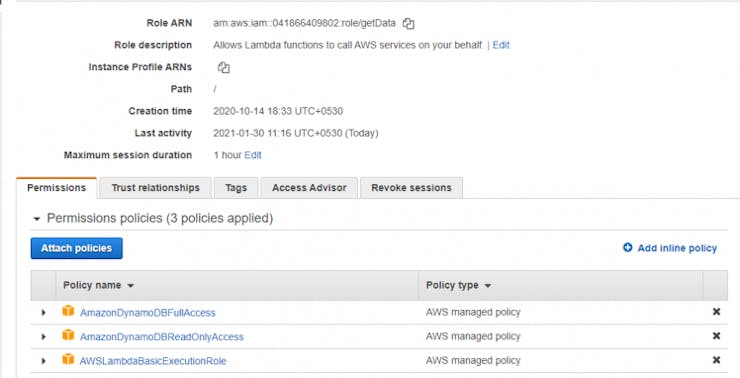
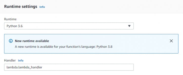
Also change runtime setting in lambda function. Edit handler lambda_function to only lambda (if you copy paste my code).
Google action :
Account linking and setup for google action:
Installed Live Module
With the completion of this project, you now have a functional smart home system that can be controlled using voice commands through Amazon Alexa and Google Home. Enjoy the convenience and efficiency that this system brings to your home!
Downloads
Schematics


