Smart Home Control System With Touch Screen
by christidisp in Circuits > Arduino
5565 Views, 23 Favorites, 0 Comments
Smart Home Control System With Touch Screen
In this project, I have shown how to make a Smart Home Control with Arduino Uno and Nextion touch screen to control door lock system, temperature and daytime monitoring.
During the article, I have shown all the steps to make this smart home system.
This Home Automation system has the following features:
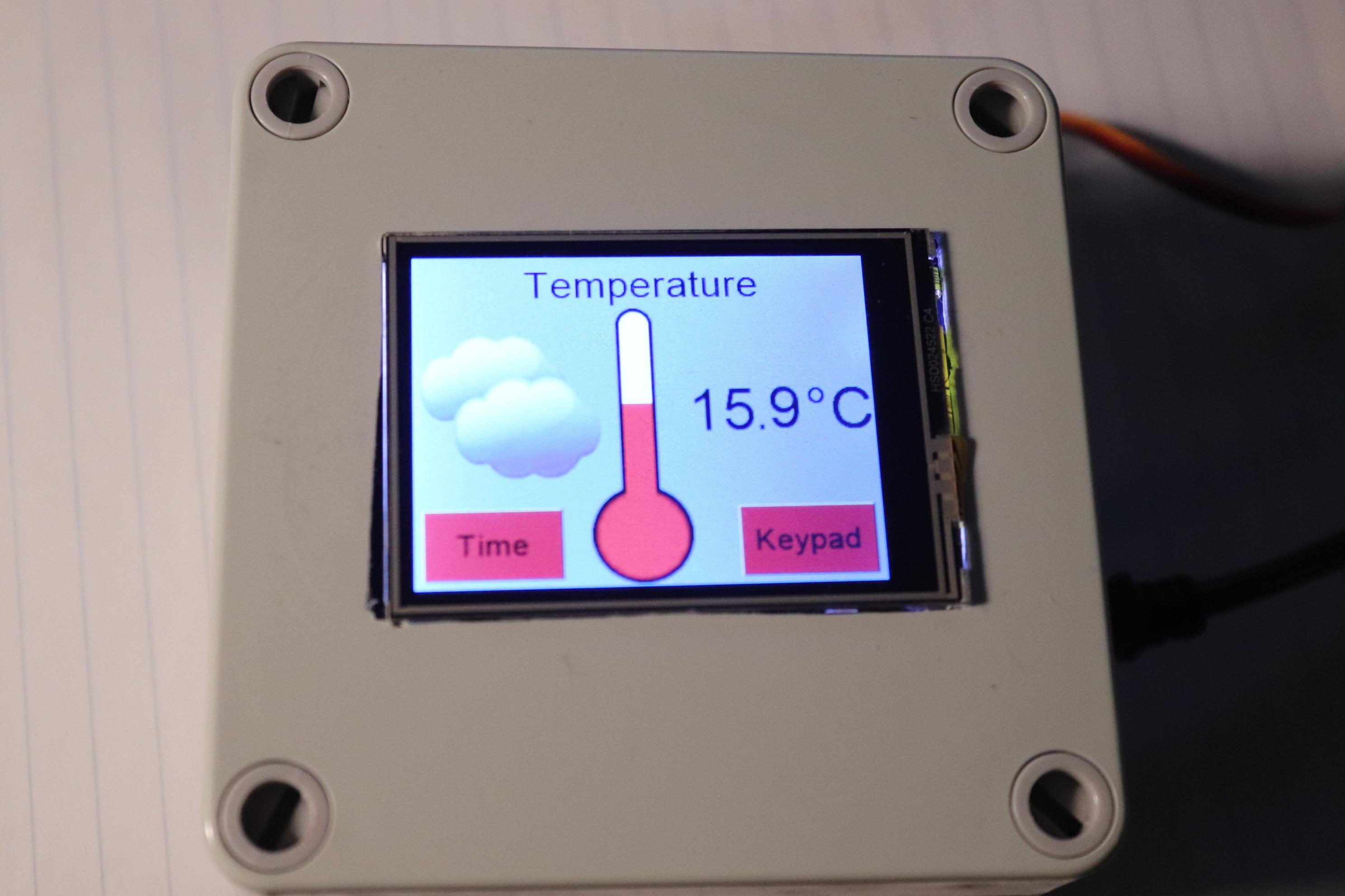
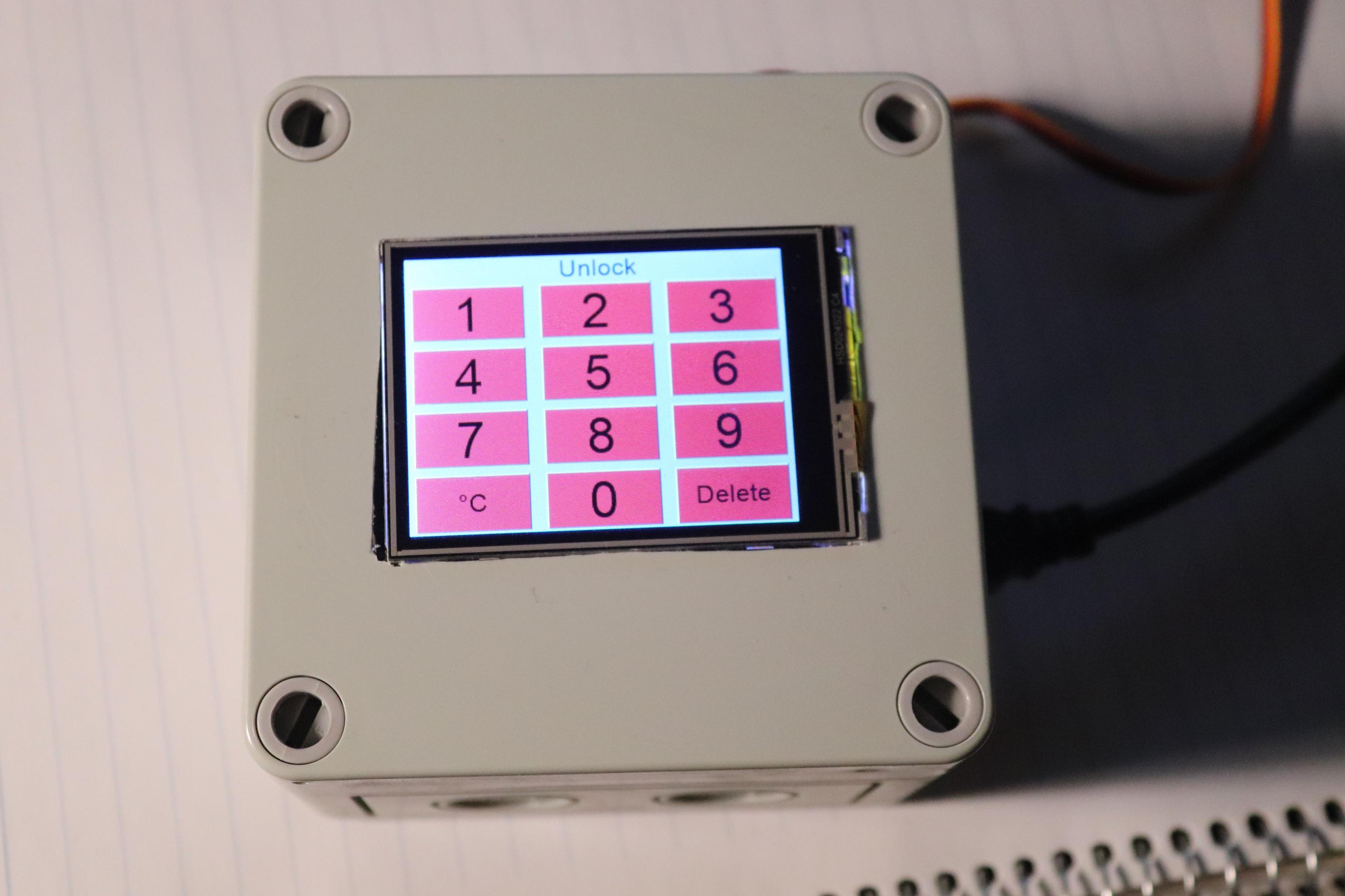
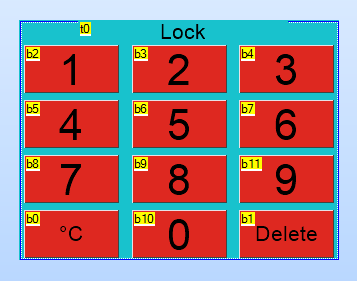
- Control Lock - Unlock door with Touch Screen Keypad
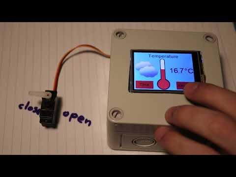
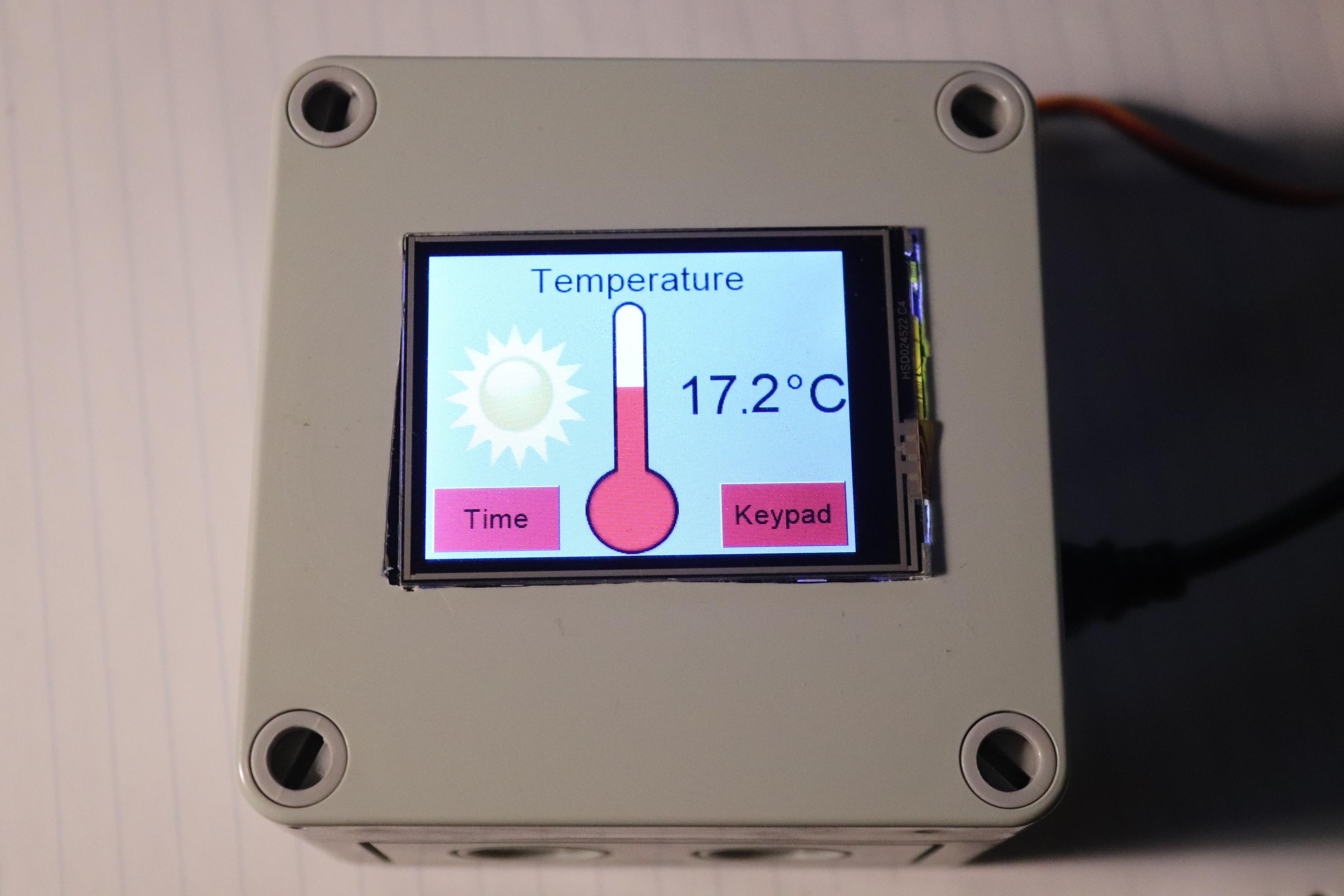
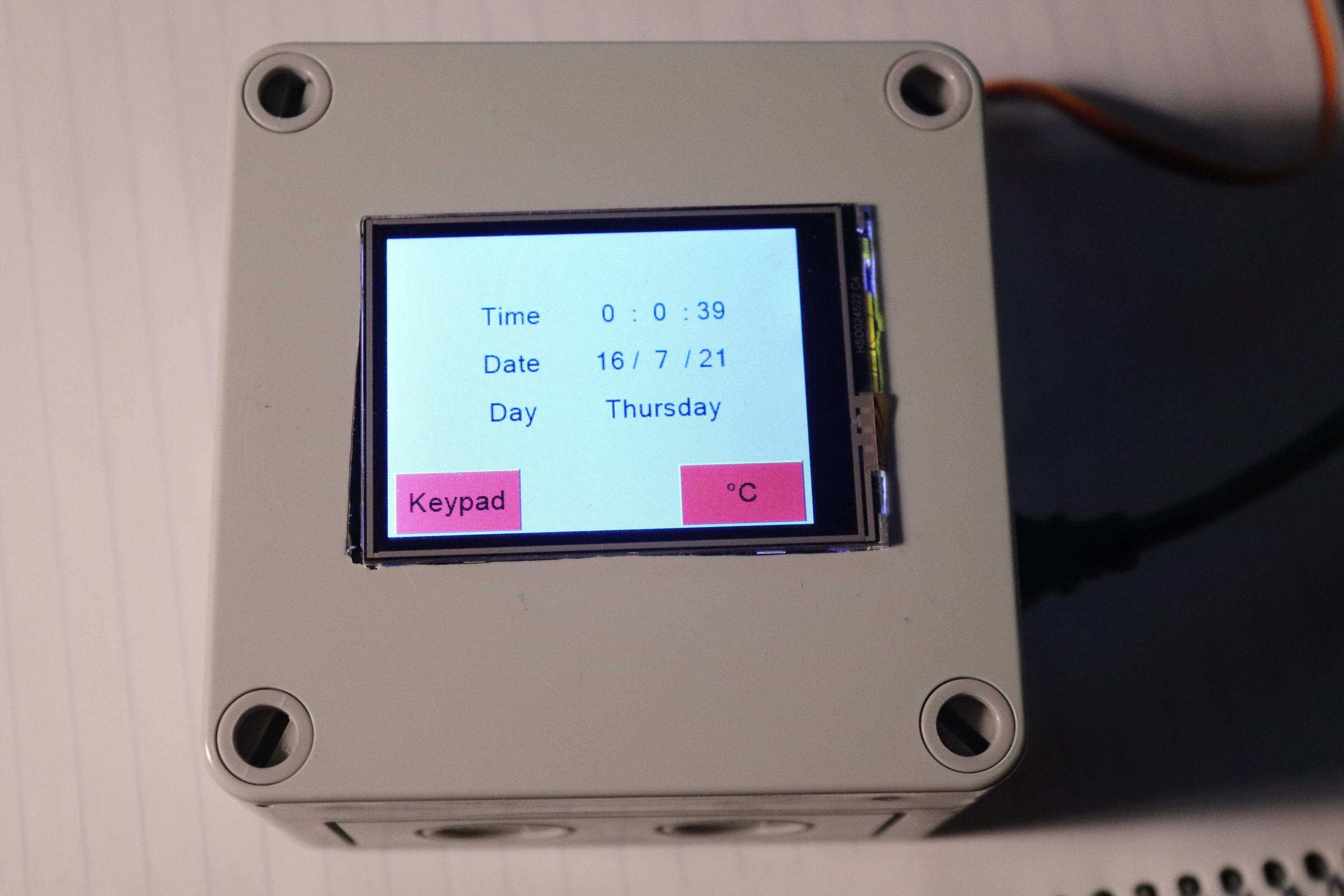
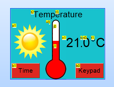
- Temperature measurement and monitoring
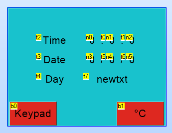
- Real Time date/day/hour monitoring
Supplies
- Arduino Uno
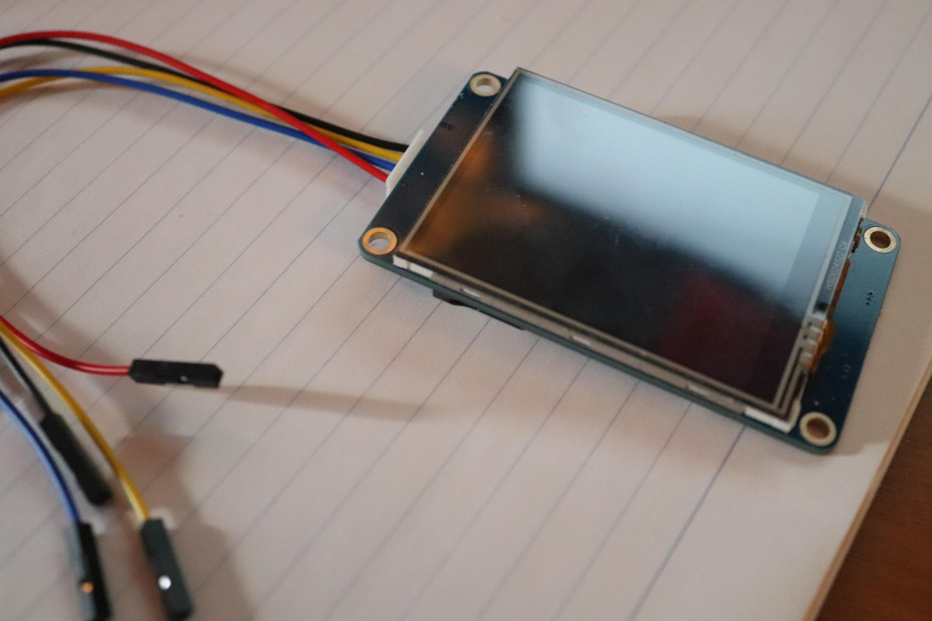
- Nextion Touch Screen
- LM35
- DS1307
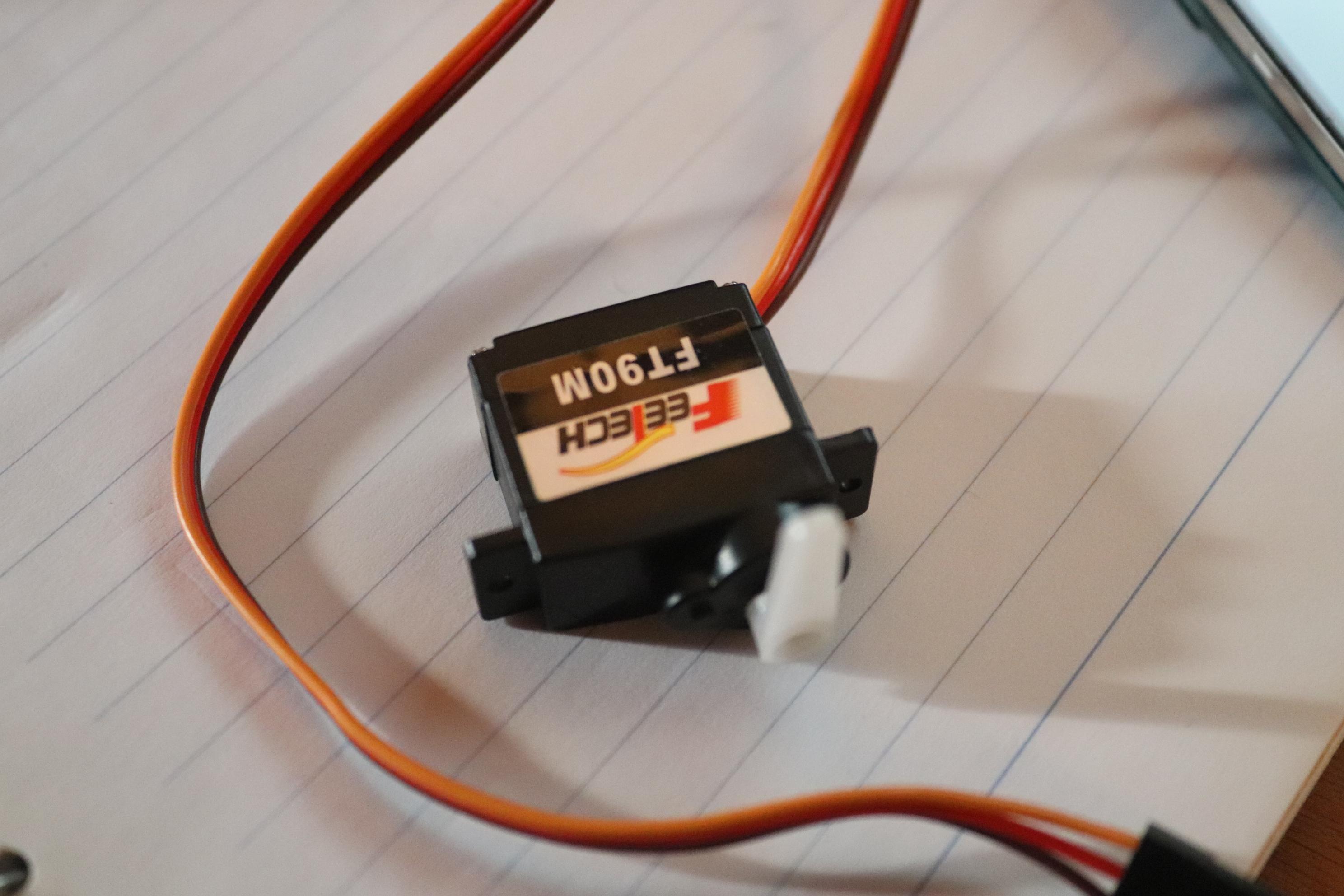
- Servo Motor
- Buzzer
- Mini Breadboard
- Plastic Case Box
For this project you will need the following components
Circuit Diagram of the Home Automation Project
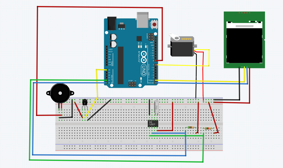
- A4 -> SDA
- A5 -> SCL
Preparing the Components
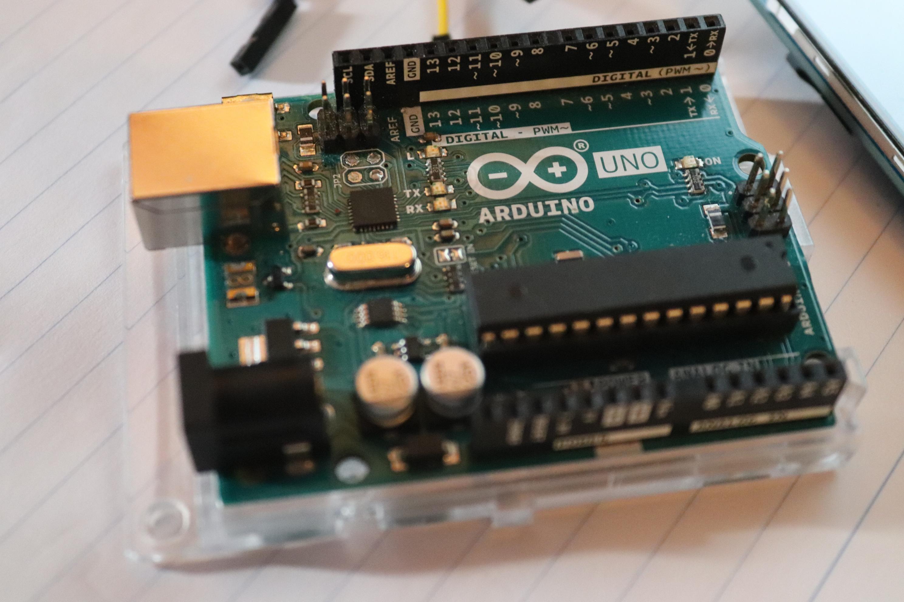
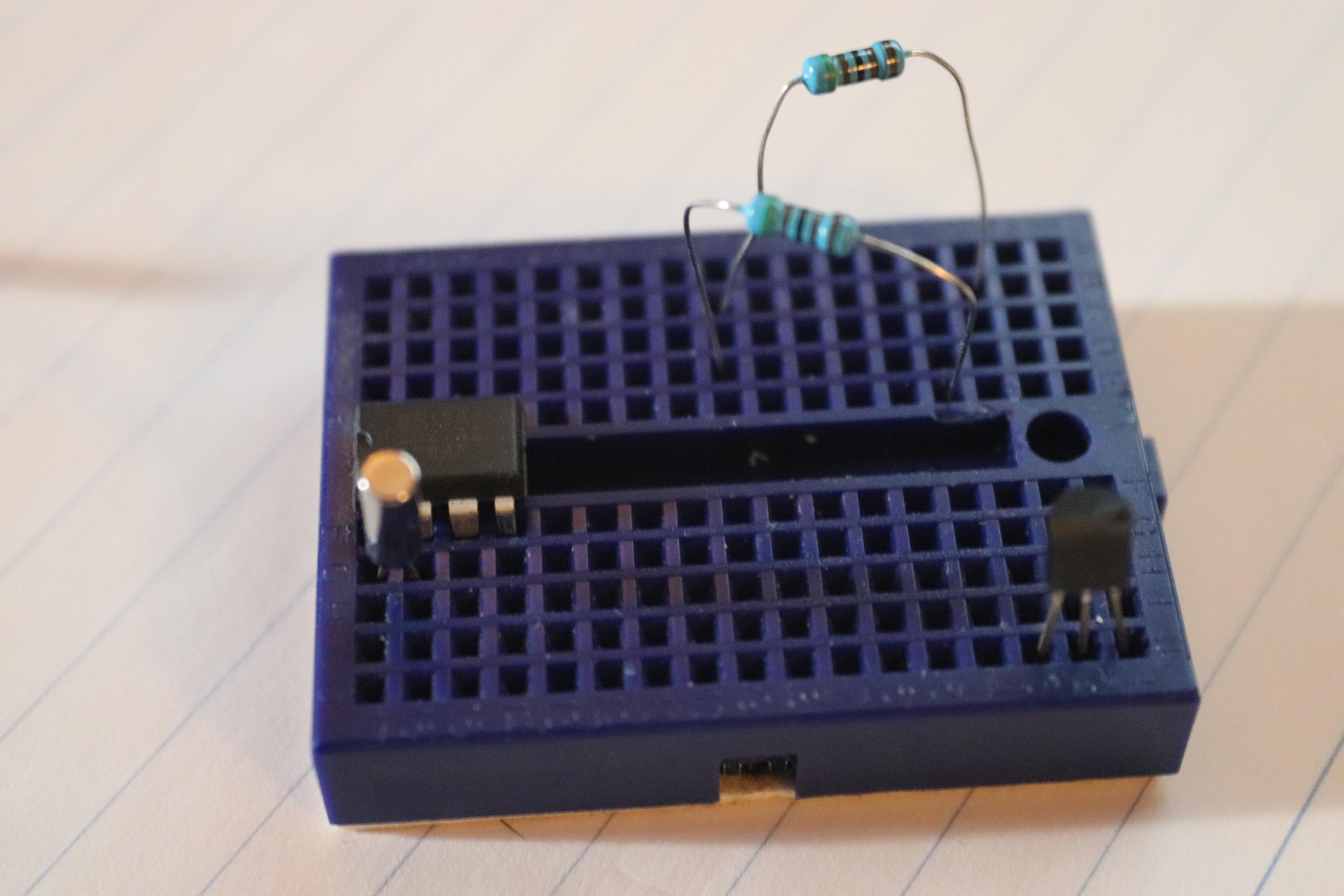
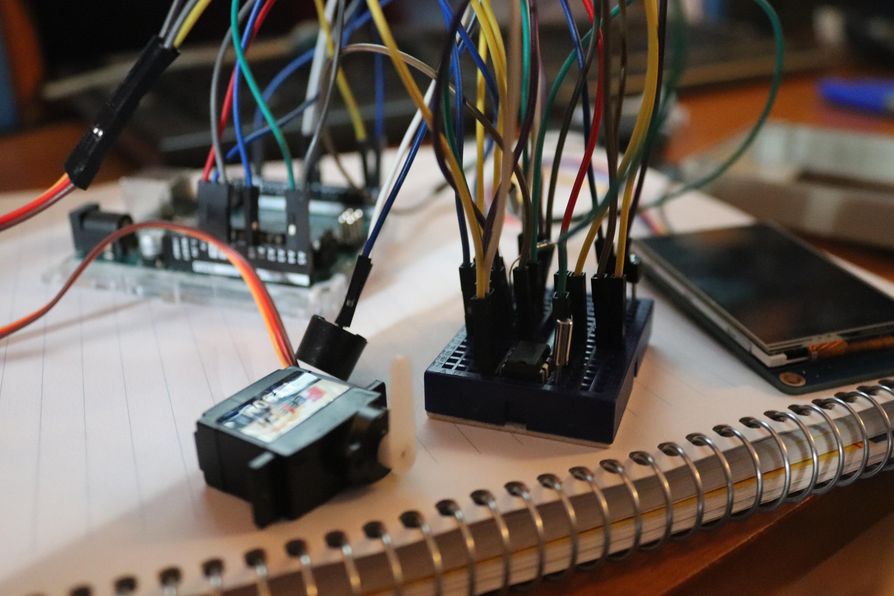
Connect wires to the Arduino
Carefully follow the wiring configuration table provided which shows the Arduino pin numbers and the associated pin numbers.
Arduino Code

1. Upload and Test the code
Upload the code through the Arduino IDE
Downloads
Nextion Code
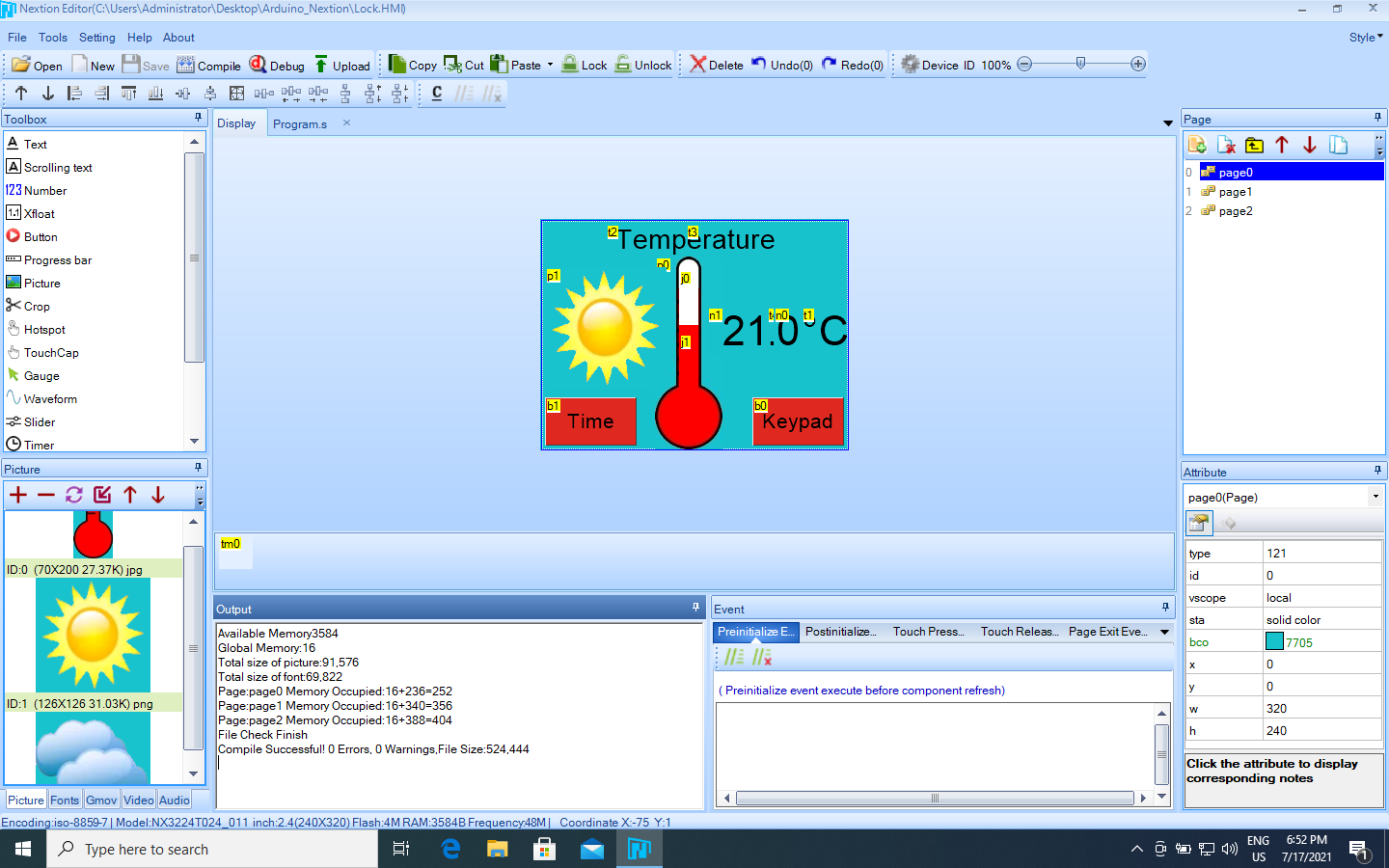
1. Upload and Test the code
Upload the code via Nextion Editor.
(To use Nextion code file, change the .ino to .HMI)
Downloads
Case Preparing
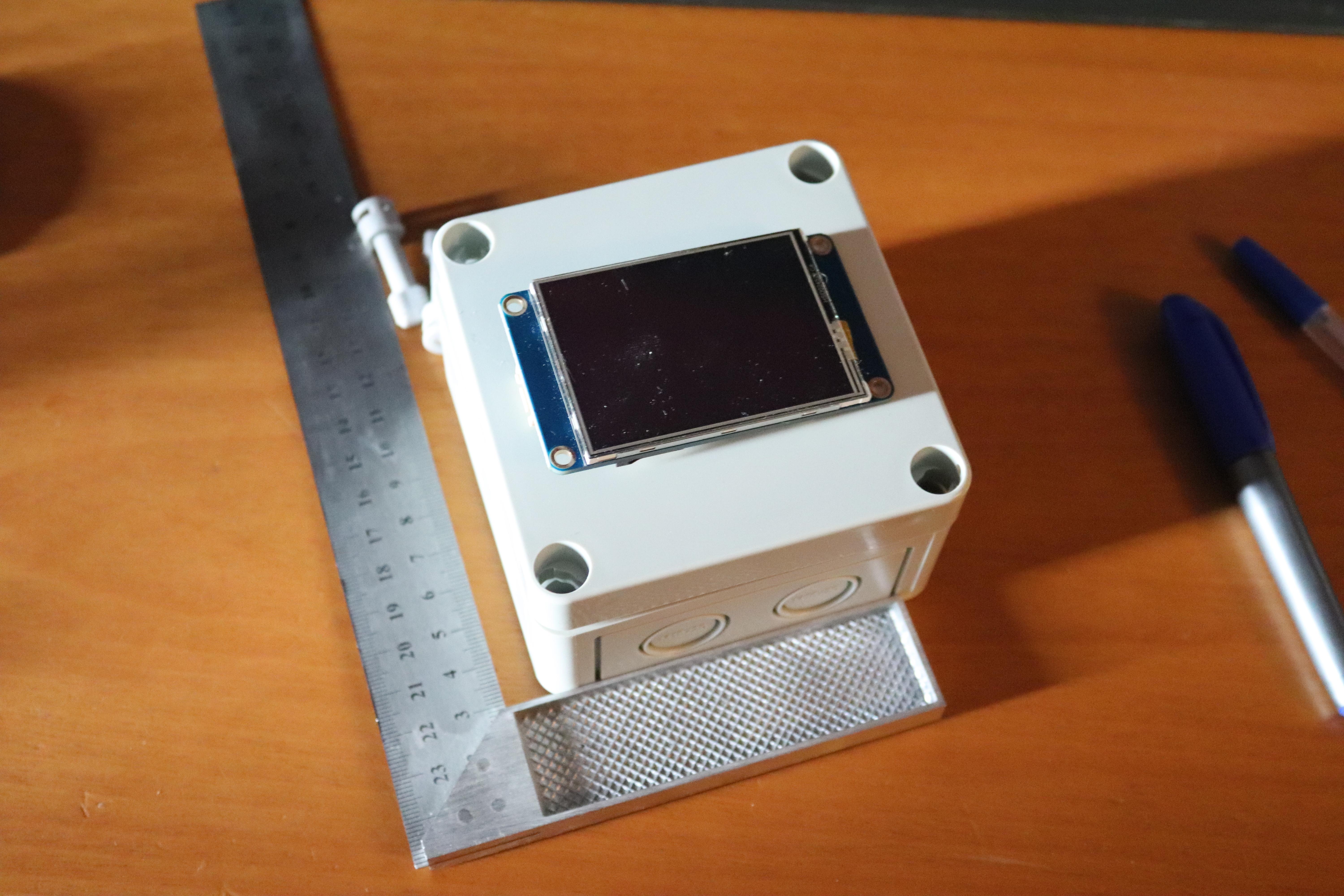
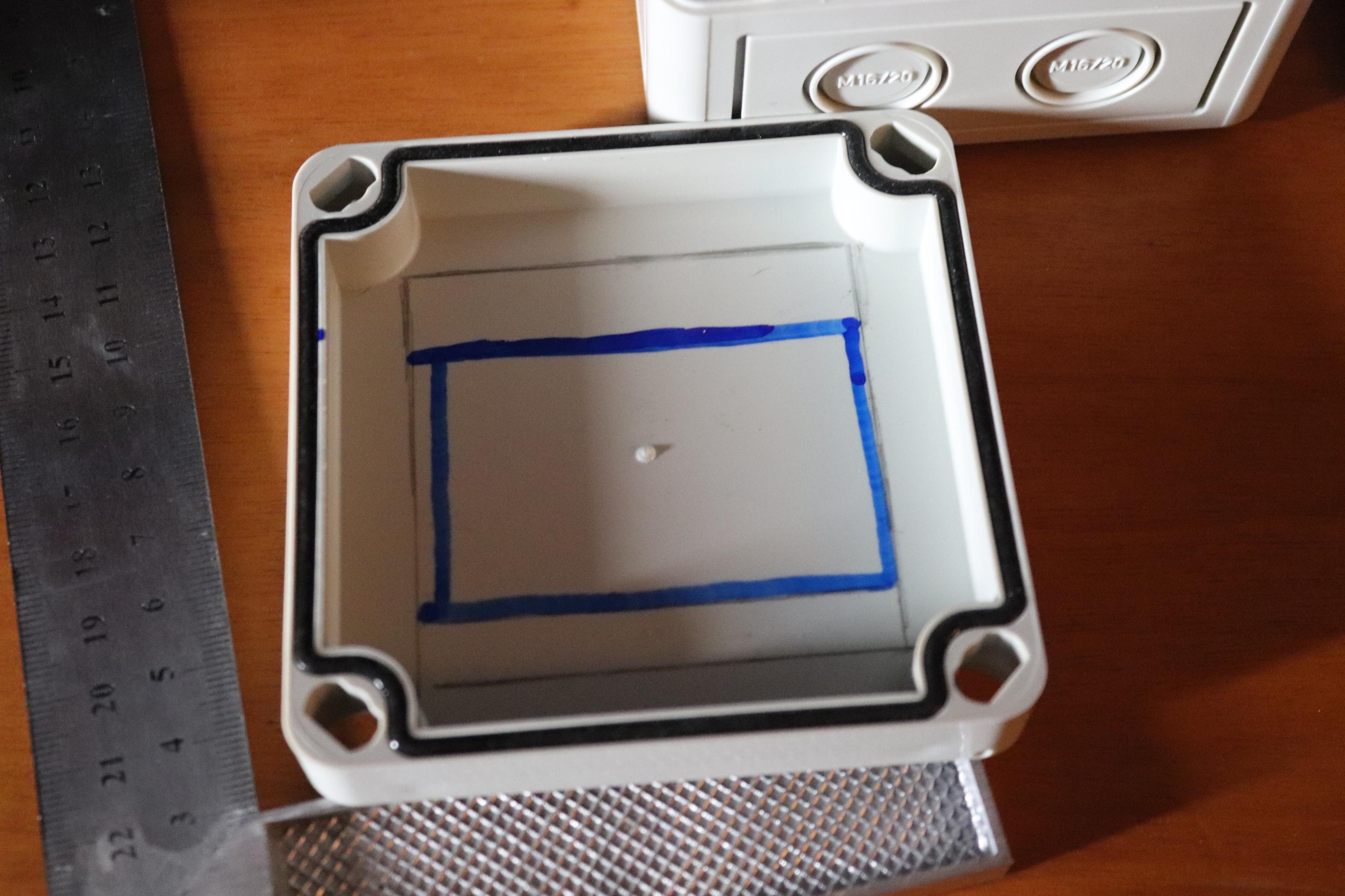
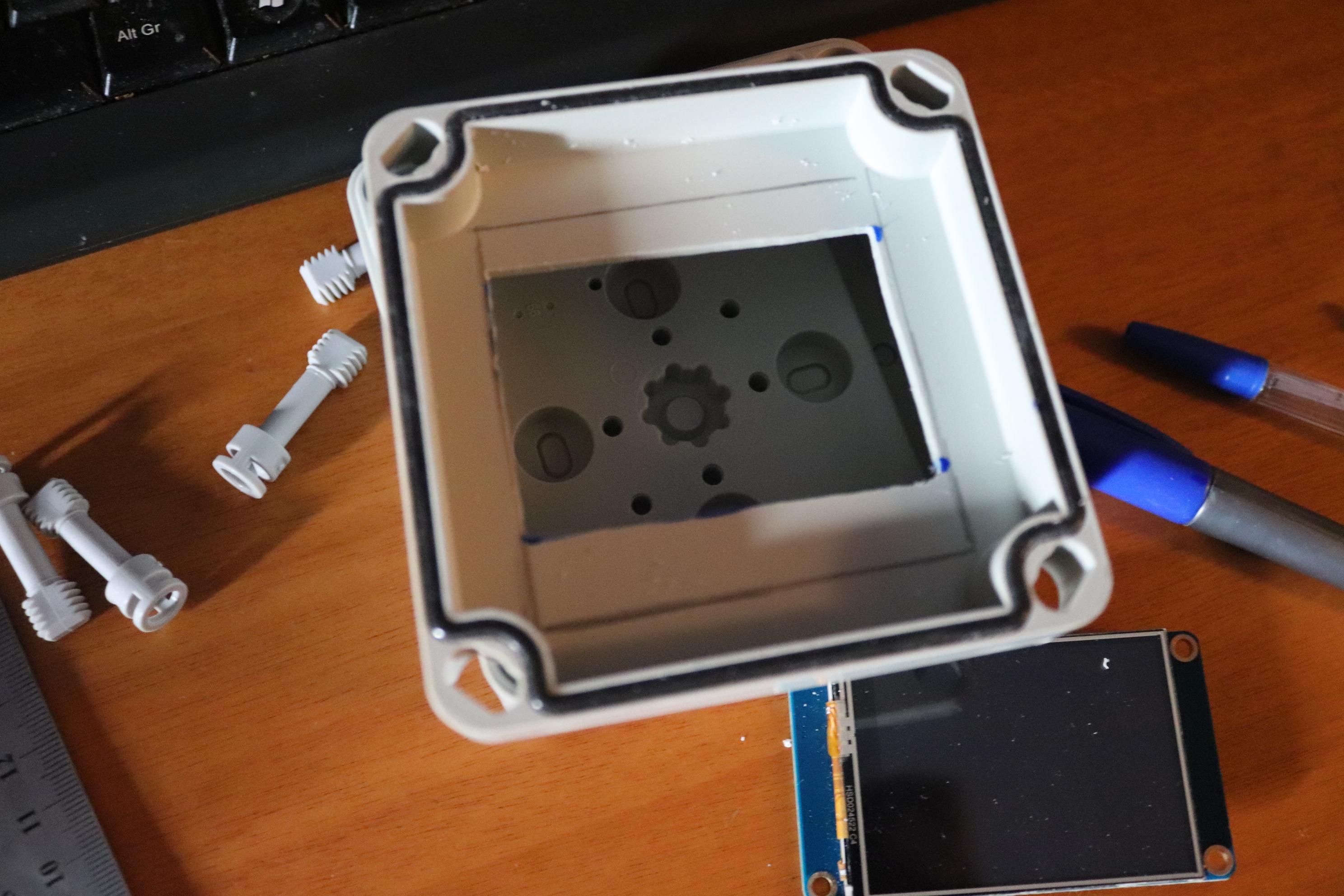
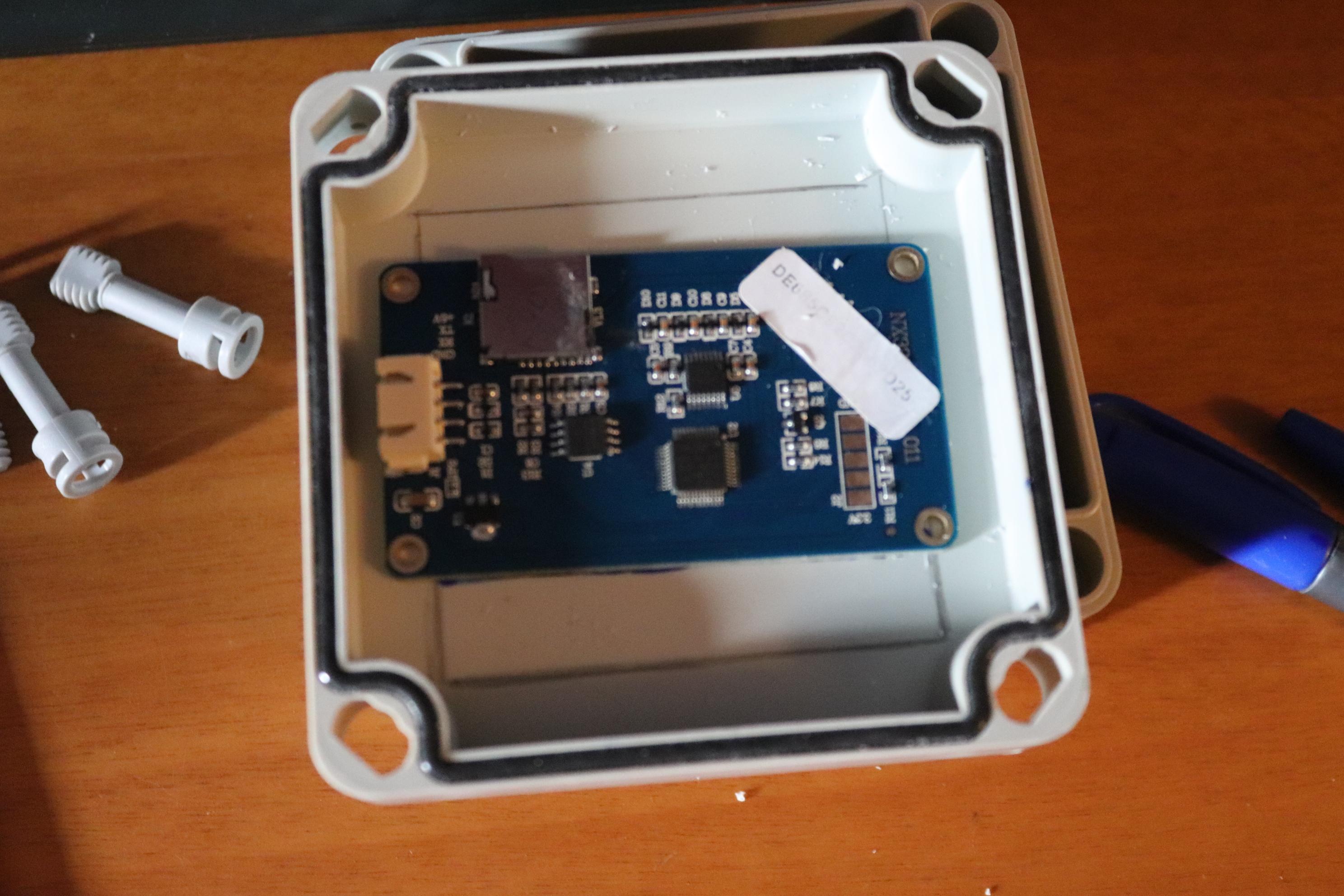
1. Cut the top of the case to fit the touch screen.
Use a pencil to mark out the dimensions of the screen and cut the plastic with a saw.
2. Cut and position the USB cables.
Open a hole for the cable with a drill.
Run and Use Project