Smart Home Automation With Energenie Sockets - Proximity Sockets
by olihart in Circuits > Raspberry Pi
811 Views, 3 Favorites, 0 Comments
Smart Home Automation With Energenie Sockets - Proximity Sockets

Introduction
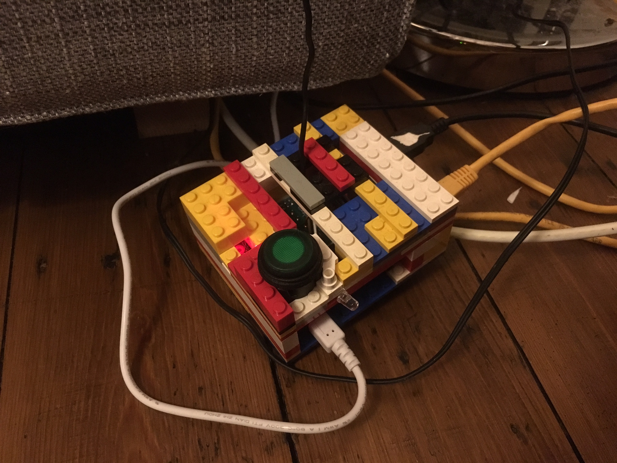
There are plenty of examples of smart home automation out there, but this one is simple and has functioned very effectively for a year in my house so I hope you like it. When you are finished you will have a device that can scan the network to see if you are in the house, according to whichever wi-fi enabled device you keep on yourself, and can control a set of sockets using an RF antenna. So now, when you walk into your home, the lights will come on and when you leave they will turn off, purely from your presence (also you can save a lot of energy on appliances which don't need to be on when you are not there, like wireless speakers).
It runs off a Raspberry Pi 2 model B, and utilises the pi-mote from Energenie, although I am sure that any RF controlled socket could be hacked to work with the right kit. It is coded in Python, mainly using the nmap-python library for port scanning on your local network.
Requirements:
1.Raspberry Pi - I have used a 2 Model B, but any would work (not sure of the reliability of a zero over a wireless network though) - connected to your router (ethernet if possible).
2.Energenie Pi-mote board and sockets
3.Length of wire and soldering iron if possible
4.Optional button and LED override
Step 1: Assembly
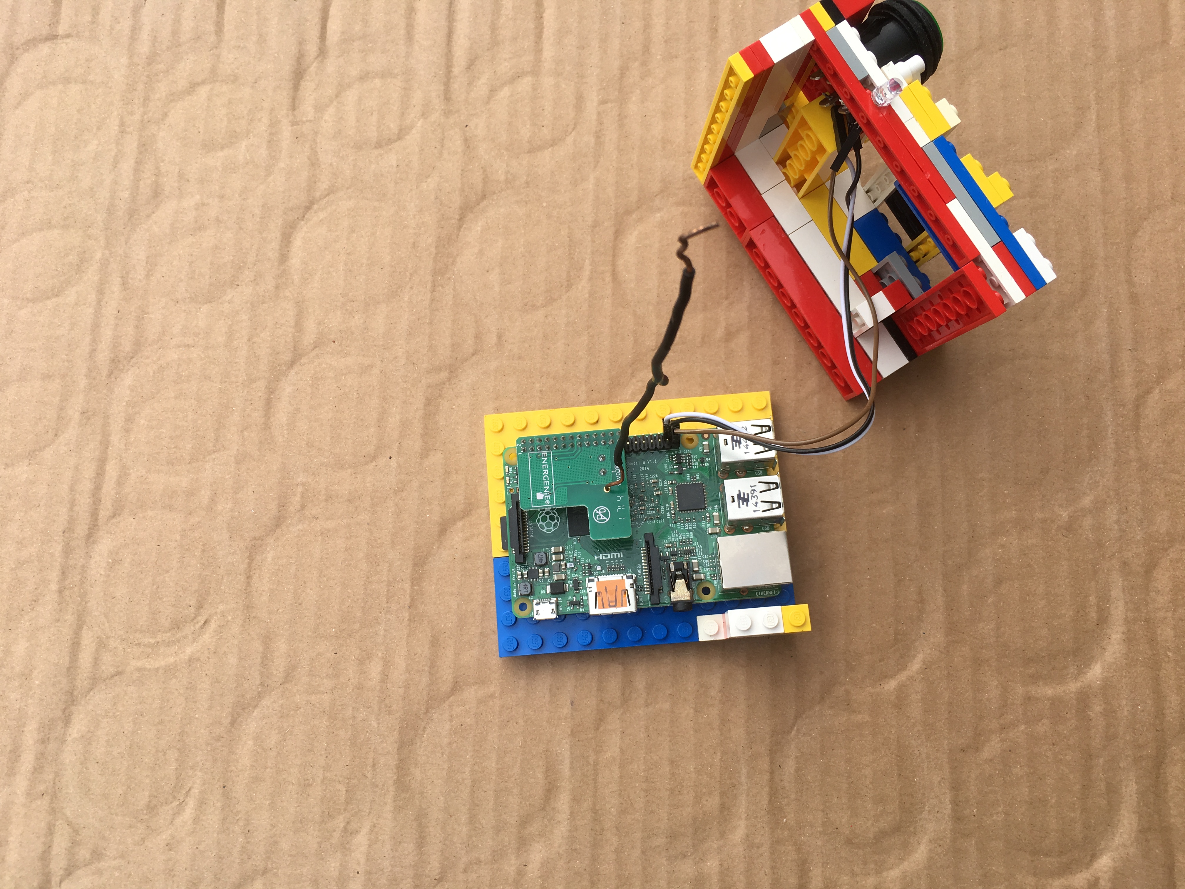
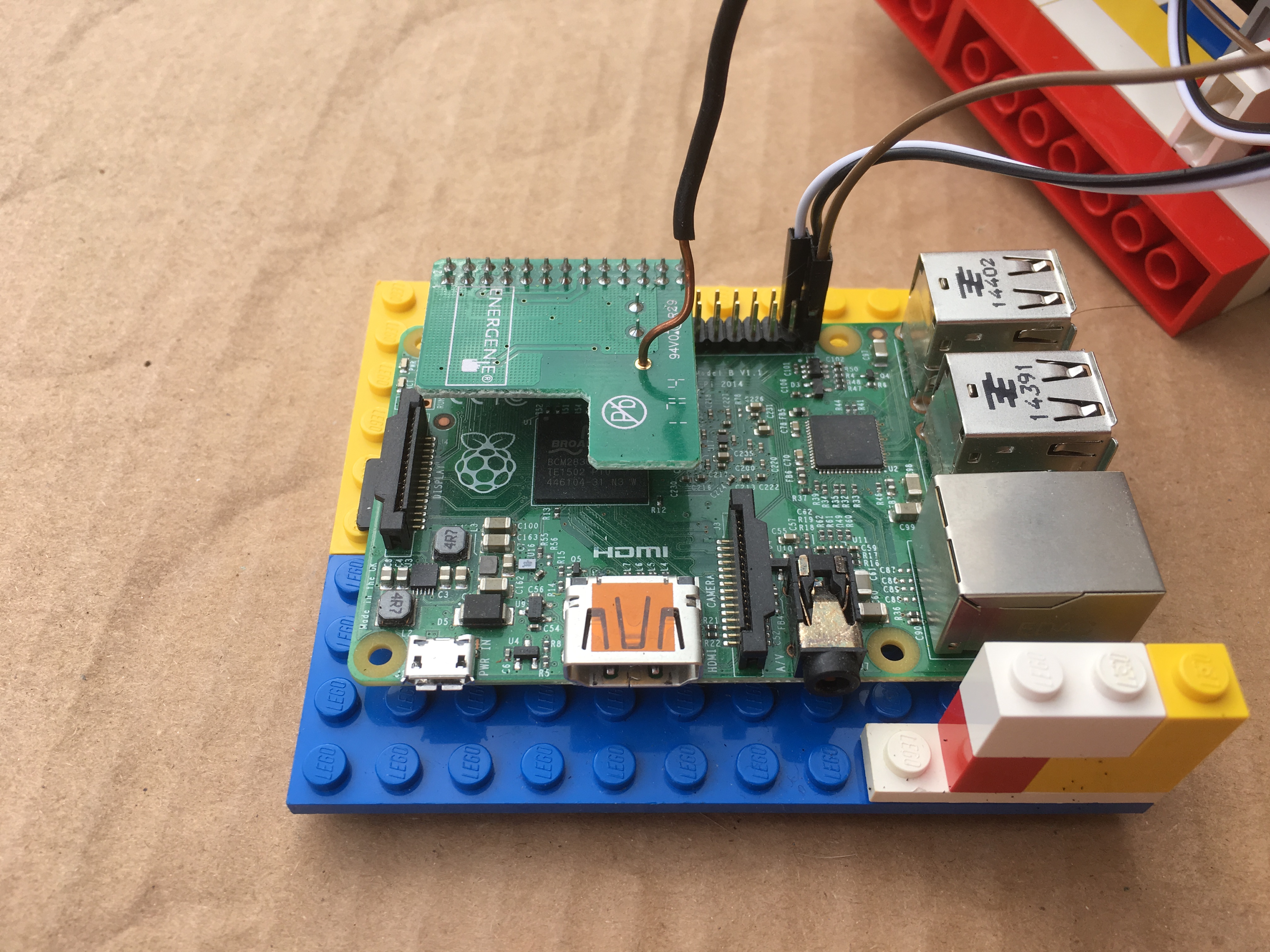
There is no need for me to repeat the basic set-up instructions here, the Pi-mote has its own instructions which are fairly comprehensive.You can run the practice code to check that the switches are operating correctly.
https://energenie4u.co.uk/res/pdfs/ENER314%20UM.pd...
Whilst the board has an antenna on, it is recommended for greater range (>5m) to add a wire antenna as shown in the image (vertical black wire). The signals are transmitted at 433MHz so the antenna should be roughly 1/4 * v/f ~= 15cm long.
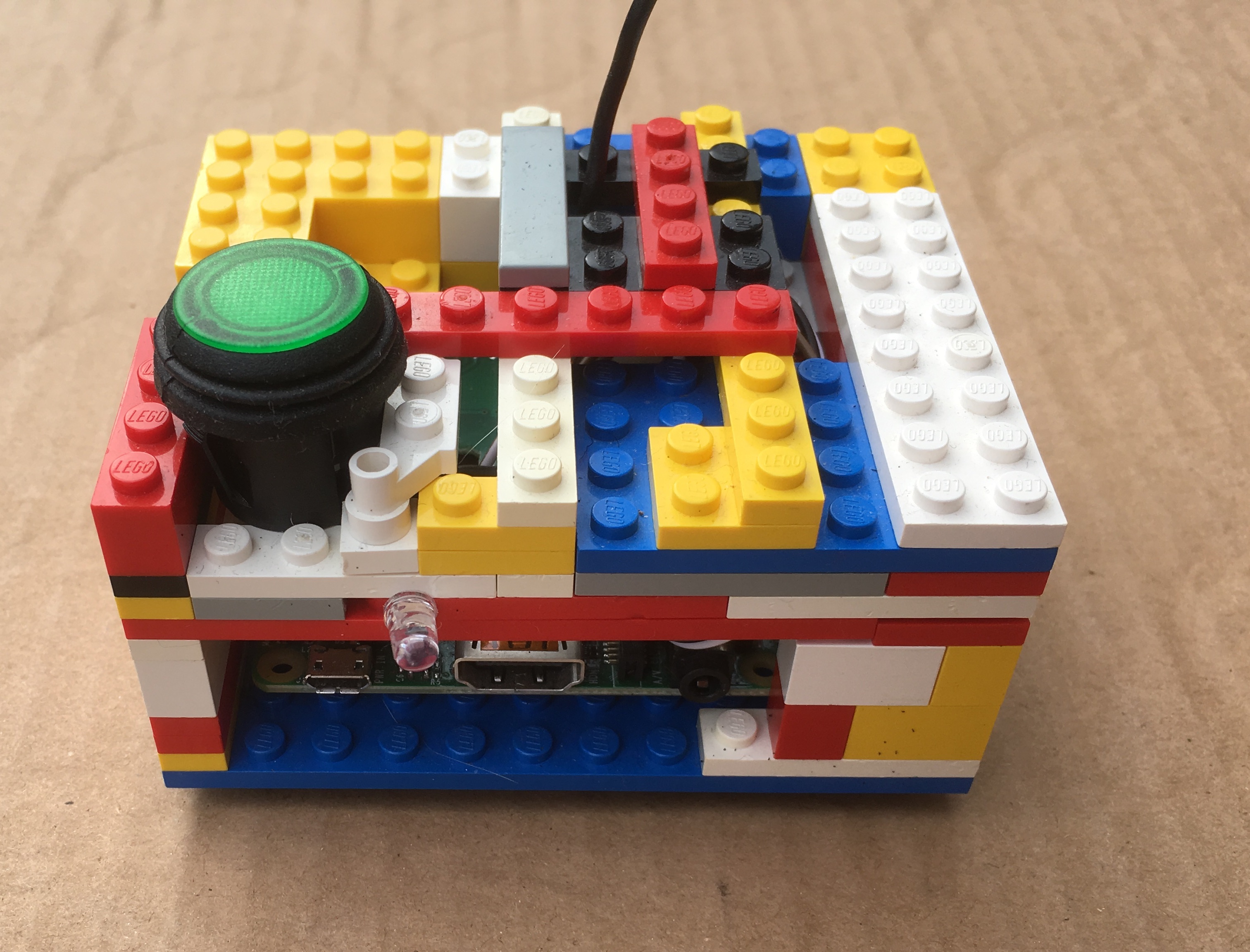
I've also added a lego caseworks to mine, I'll let you be the judge of the quality of that job : )
Step 2: Finding Your Devices' IP Address
As mentioned the main software tool is a library called nmap which has been adapted for python and can be downloaded from here: https://pypi.python.org/pypi/python-nmap/0.6.1 It can do loads of stuff: https://nmap.org/.
We will initially do a broad scan of the network to find the right devices and in the main program run a scan of the network.
Open a python terminal and type:
import nmap
nm=nmap.PortScanner()
nm.scan(hosts='network IP address range', arguments='-sP')
The IP address range will be something like: '192.168.0.1/24'
This will give you a long list of the devices on your network, you will need to use trial and error to determine which devices you are interested in.
This step is more easily done with arp-scan commands or ping outside of the python interpreter, which give you some information on the devices, but since we were using the python-nmap library anyway I thought I'd put this one in.
Once you have found which devices you want to use as the presence controllers e.g. mobile phones, tablets etc. Note their IP addresses. This works on both dynamically and statically controlled IP address networks.
To confirm that you have the correct device, you can disconnect it from the network, and re-run the scan, it should then not appear on your scan.
Step 3: Setup Your Sockets
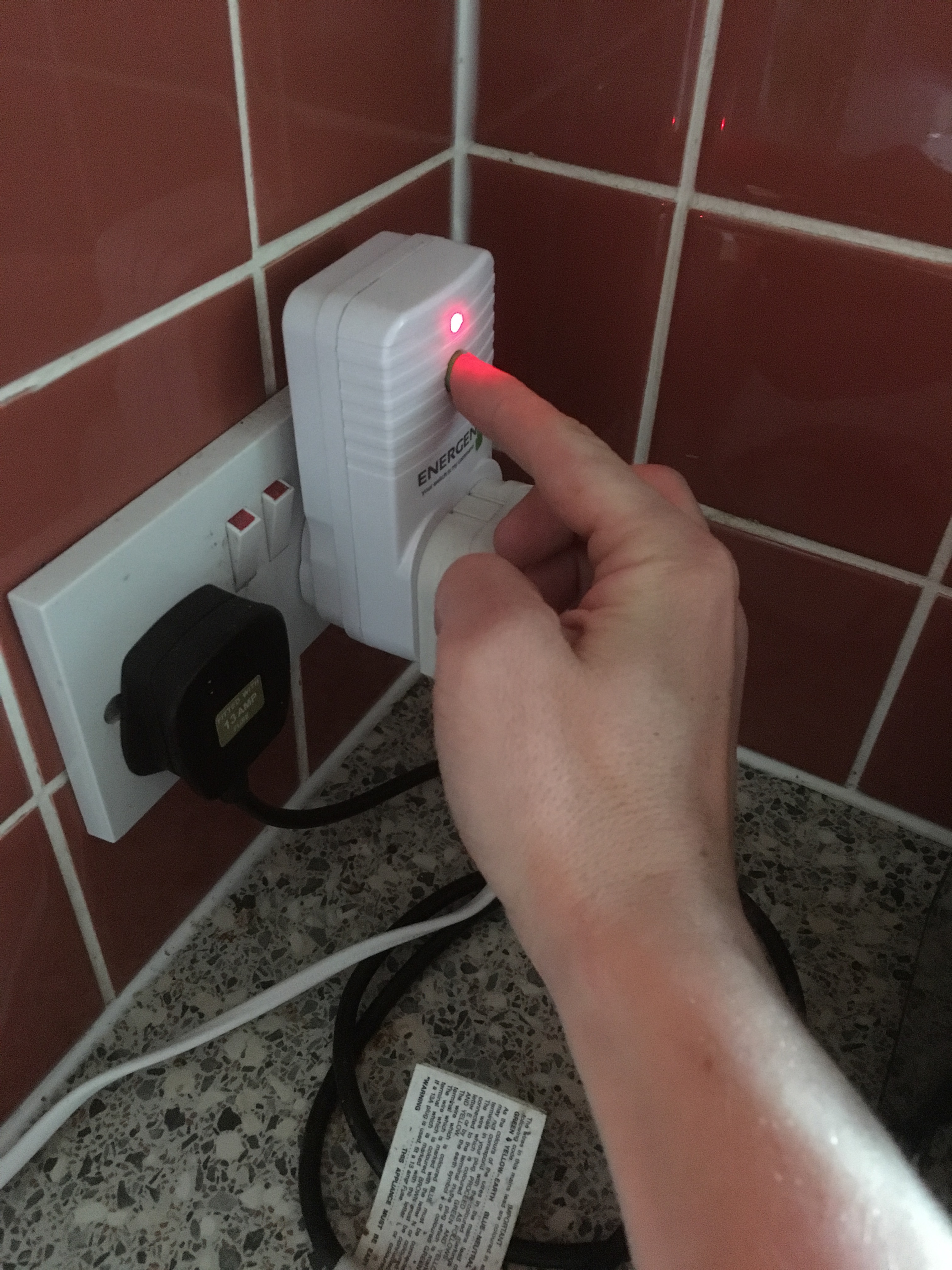
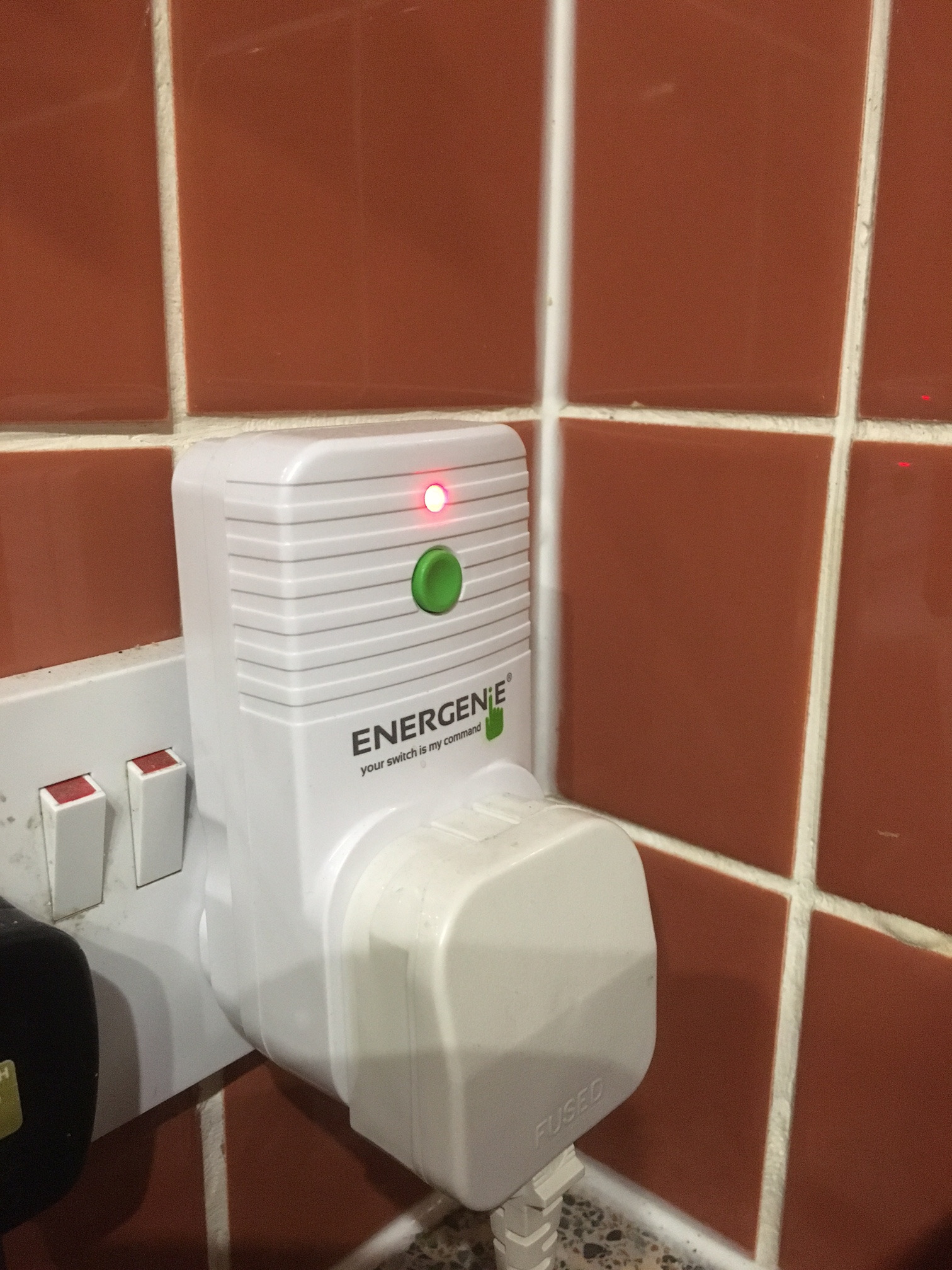
Now that you have your IP addresses, you will need to setup your sockets. This is done by holding the green button on the sockets until the red light flashes and then sending the chosen signal. The different signals are achieved by a set of 4 binary switches corresponding to digital outputs on the Pi.
There is an example code in the Energenie manual for switching, I would suggest copying this and adapting a short script which allows you to setup the sockets by sending a signal when you run the script.
Step 4: Write Your Code
And on to the final program.
I have attached the code I used, which worked for two devices for each of the occupants of our house, whilst there was an override button for anyone else.
The code works by searching the IP addresses '192.168.0.10' and '192.168.0.28'. It then looks at only ports 80 and 62078 to save time, these ports are often open for communications on mobile devices. Change the IP addresses to the addresses which you found in the last step. It also checks the button input, in this case the button is connected to pin 40 in the GPIO.setup with a pull down to ground. If any of the devices are present, or the button is on, it sends a signal to the sockets to switch on.
To avoid potential dropouts: whilst the device will turn on quickly at your presence, as there are no false positives, it will shut off after a longer period. This is because there are sometimes false negatives, i.e. it does not correctly detect a device on every scan. As I mentioned we have had no dropouts in over a year of operation using this technique.
I have also left the debug code in as this is useful for working out whether your code is running properly. Feel free to build and mod from this basis to have loads of sockets and loads of devices all interacting. Additionally you will probably want to run this code constantly on your Pi in the background whilst it is doing other things, preferably from startup. For information on how to do this, see this thread: https://www.raspberrypi.org/forums/viewtopic.php?...
You're done - Enjoy.