Weather Controlled Cat Hatch
by Ellen Dequeker in Circuits > Raspberry Pi
356 Views, 0 Favorites, 0 Comments
Weather Controlled Cat Hatch
Hello!
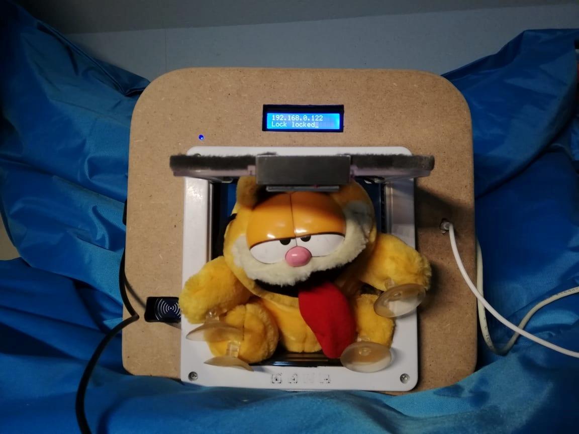
As a project for my studies at MCT Howest Kortijk, I came up with the idea to make a smart cat hatch that focuses around keeping your cat inside whenever you want or automatically if the weather isn't as great.
It runs completely on a raspberry pi with a nice interface to keep track of everything. This is a project made in three weeks and in this instructable i will tell you everything you need to know to be able to make one yourself.
If you have any questions, be sure to let me know.
Supplies
Main Component:
- Raspberry pi
This is the controller of the whole project.
Electronics:
- A couple resistors
- Breadboard and wires
To connect the components.
- Power supply module
Giving the right amount of power to each component.
- BC337 Transistor
- Diode
- Potentiometer
Setting the contrast of the LCD display.
Sensors and modules:
- Light Dependent Resistor
- DS18B20 One Wire temperature sensor
- Rain sensor
- 2 x RC522 RFID reader
- MCP3008
- PCF8574
- Electromagnet
- Neopixel
- LCD
Case:
- Wood
- Existing cat hatch
Used tools:
- Wood glue & glue gun
- Cable ties
- Sandpaper
- Drill
- Screwdriver / screws
- Soldering iron
- Jigsaw
Setting Up Your Pi
The first step in the process is getting you pi ready to use.
To start you are going to need an image and software to write on your sd card.
Image: https://www.raspberrypi.org/software/operating-systems/
Installing software: https://sourceforge.net/projects/win32diskimage/
Once everything is done you can put the sd card in your computer and folow the next steps.
- Open win32
- Select the downloaded image file
- Choose where it needs to write to
- Click write
- Wait until it's done
If it is done you need to adjust some things before you can get access.
- Go to your sd card and search for a file named "cmdline.txt" and open it
- At the end of the line add "ip=192.168.168.168" and save this file
- Create in the same location an empty file without extension named "ssh"
Now you can put the sd card in your pi and connect with putty via "192.168.168.168 /22".
Putty: https://www.chiark.greenend.org.uk/~sgtatham/putty/latest.html
You will have to login, use this information: User: pi & Password: raspberry.
Wi-Fi connection
Get root rights:
sudo -i
wpa_passphrase "ssid" "password" >> /etc/wpa_supplicant/wpa_supplicant.conf
Reconfigure the wireless network card:
wpa_cli -i wlan0 reconfigure
Update
When you are connected to the wifi you can update your pi.
sudo apt-get update
sudo apt-get upgrade
MariaDB Database
sudo apt-get install mariadb-server
Apache2 Webserver
sudo apt install apache2
Python
pip3 install flask-cors
pip3 install flask-socketio
pip3 install mysql-connector-python
pip3 install gevent
pip3 install gevent-websocket
RFID rc522 Library
sudo pip3 install spidev
sudo pip3 install mfrc522
Reboot
Don't forget to reboot before you continue.
sudo reboot
Schematic Circuit
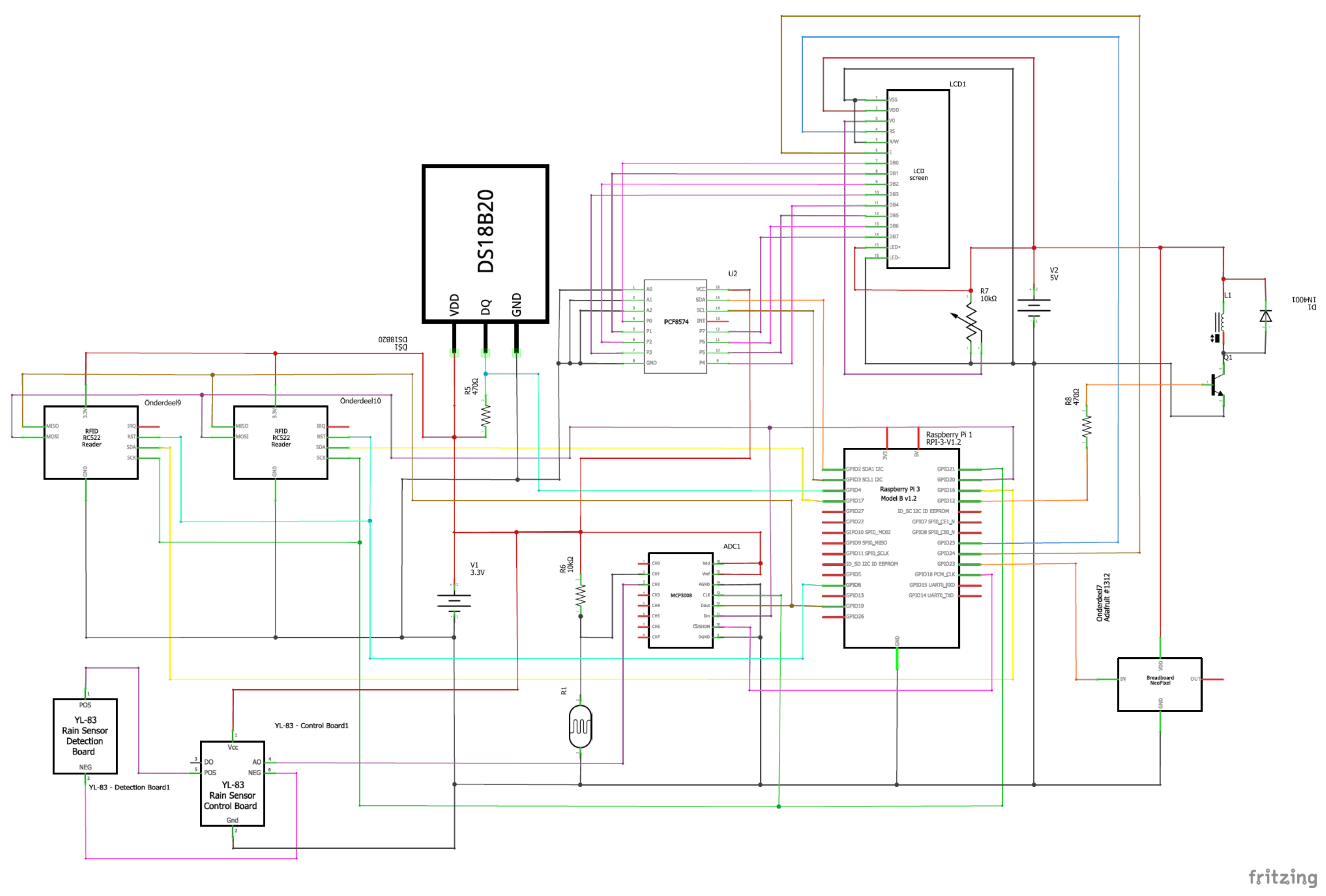
For the drawing of mij circuit i used Fritzing, It's very usefull for complex circuits like these.
As you can see, the main parts are the One wire, LDR, RFID's, Rain sensor's
Make sure you wire everything correctly to make sure you dont have a short circuit, keep everything safe!
Database
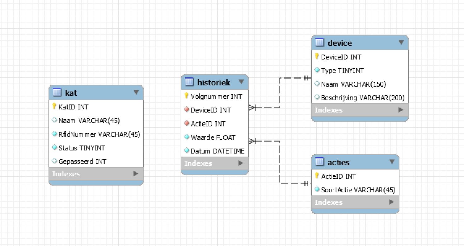
First you will need the software to install your database on.
Mysql: https://www.mysql.com/products/workbench/
Once that is done you can install the database that you can find here:
As you can see on the picture i have four tables. A table for all the devices, one for the actions, for the cats and most importantly a table that saves every action that happens that happens.
Making the Case
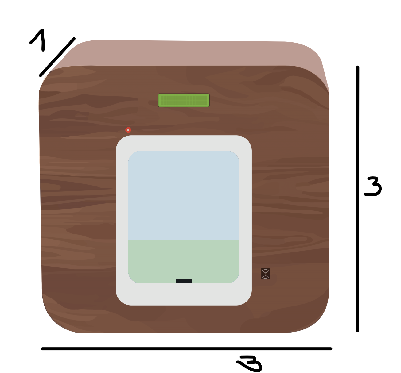
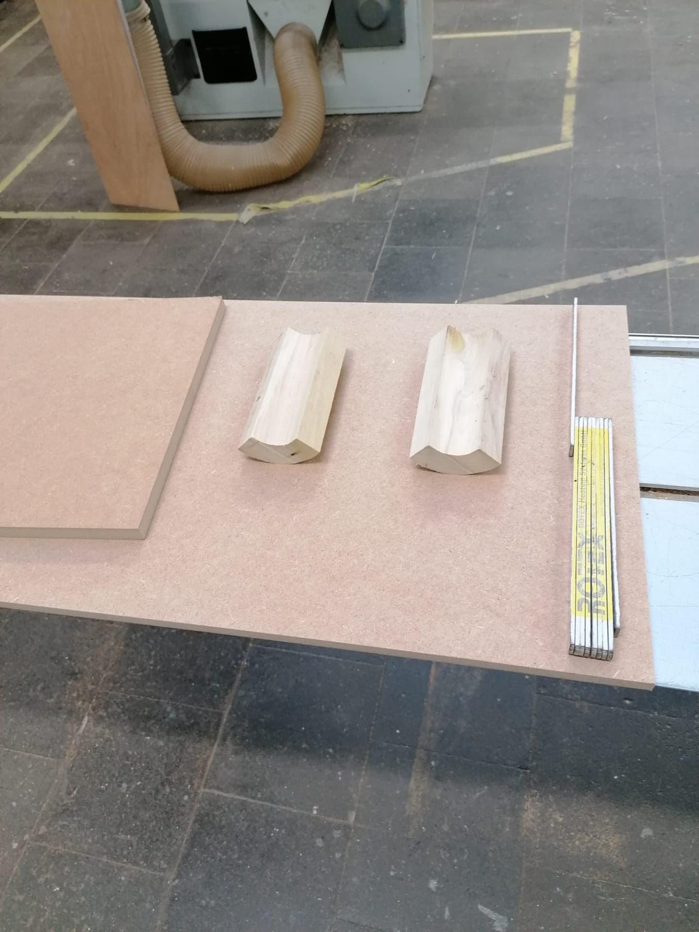
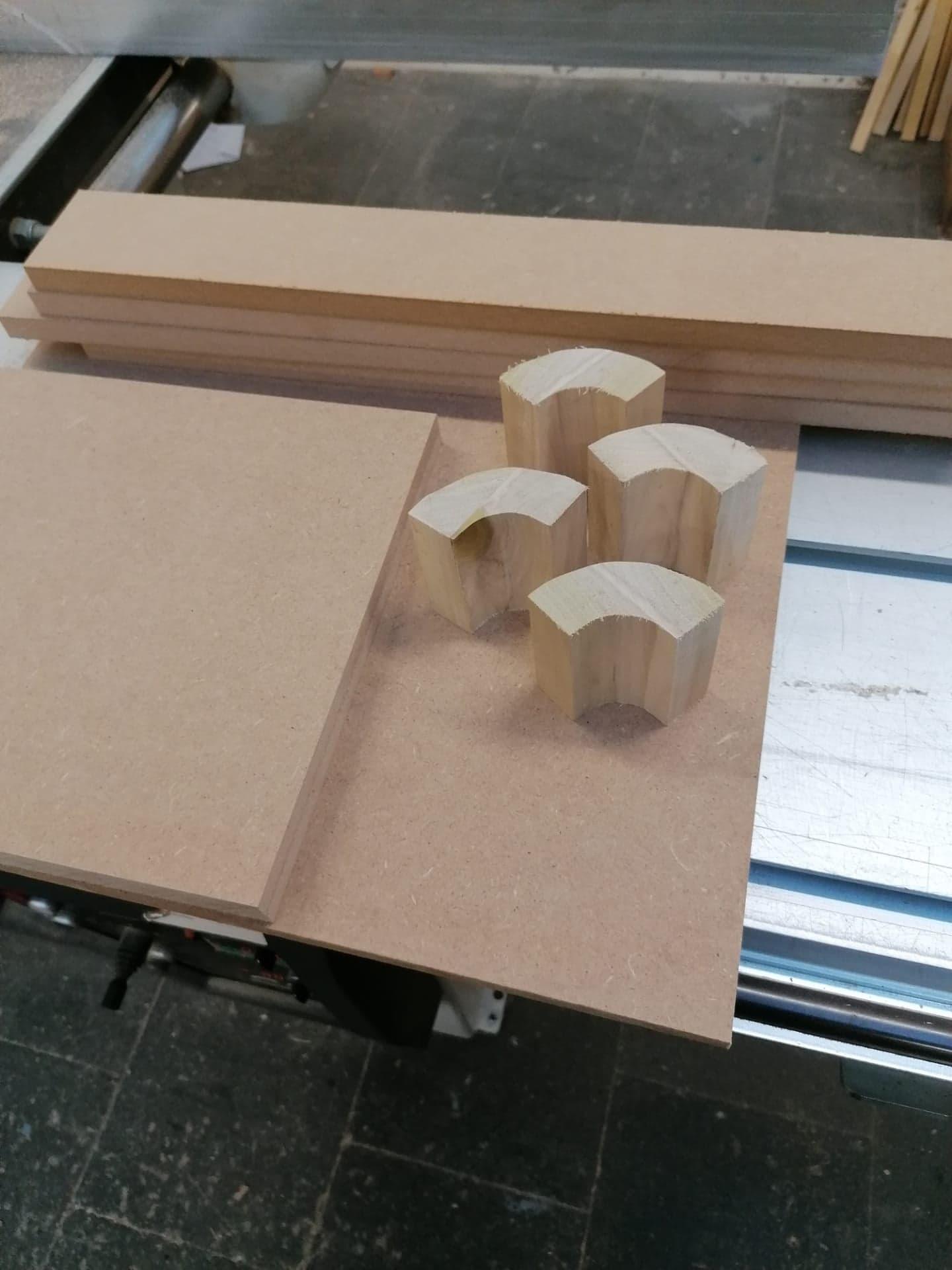
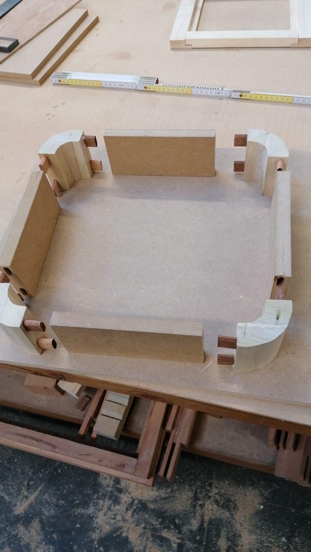
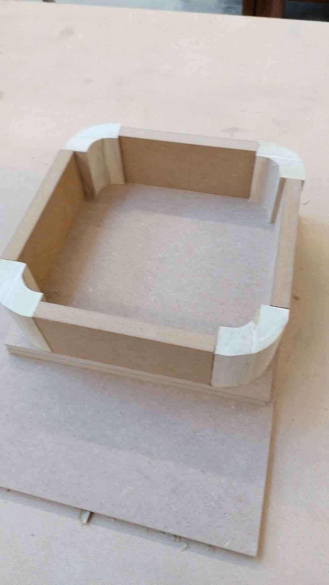
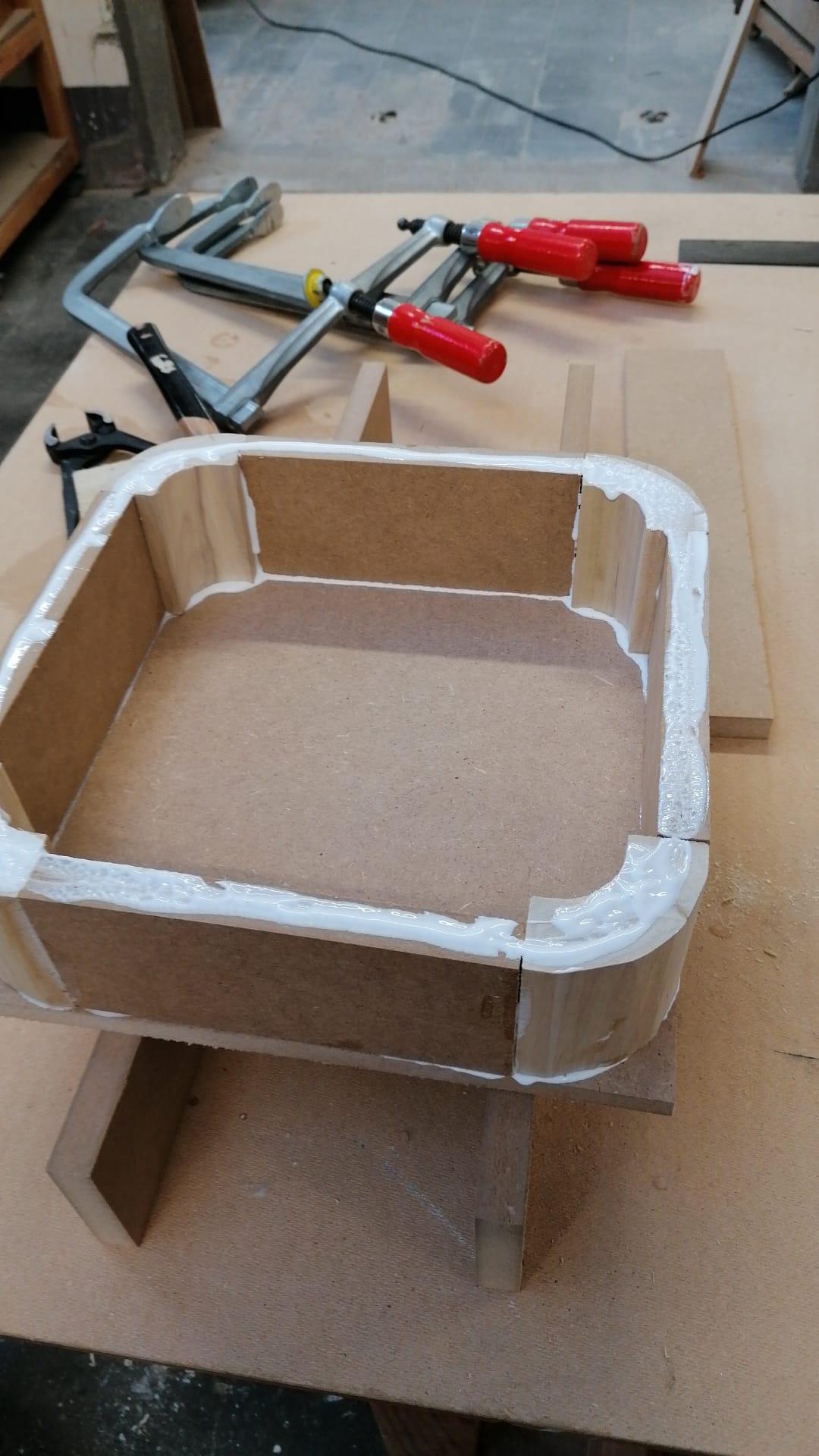
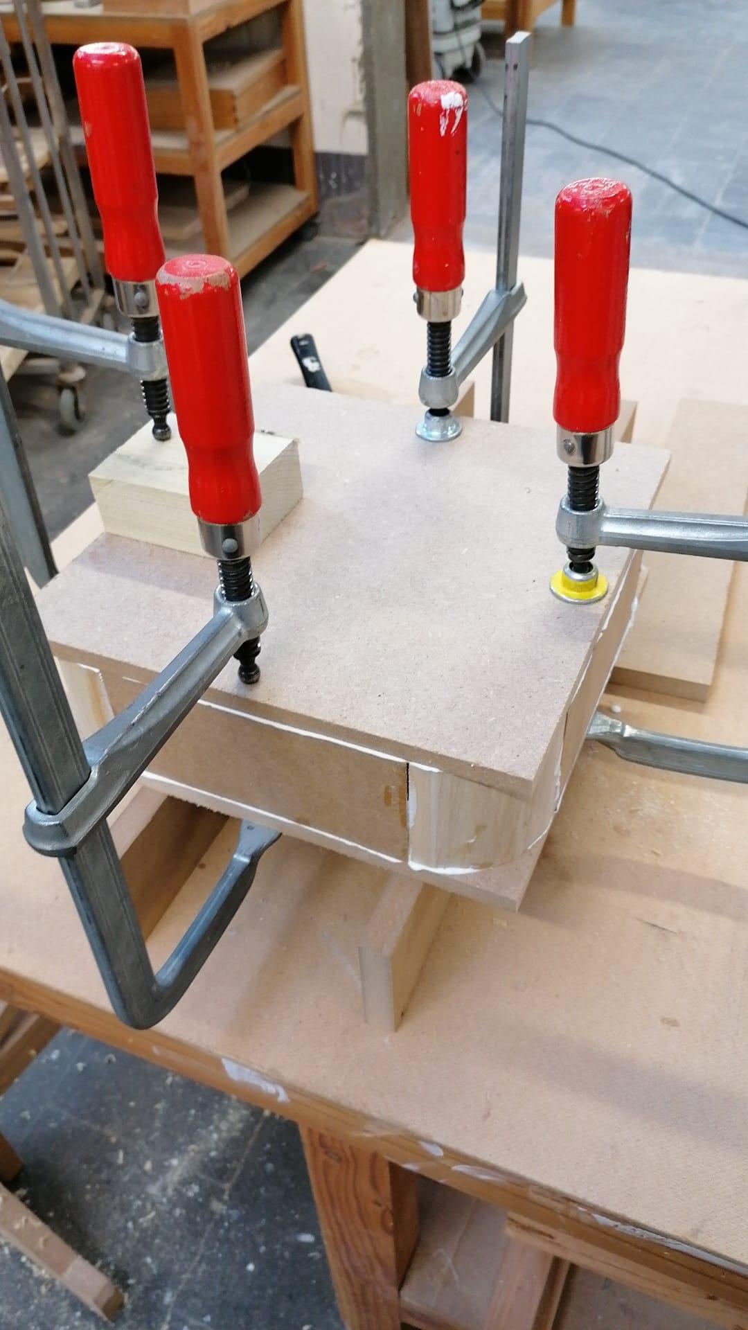
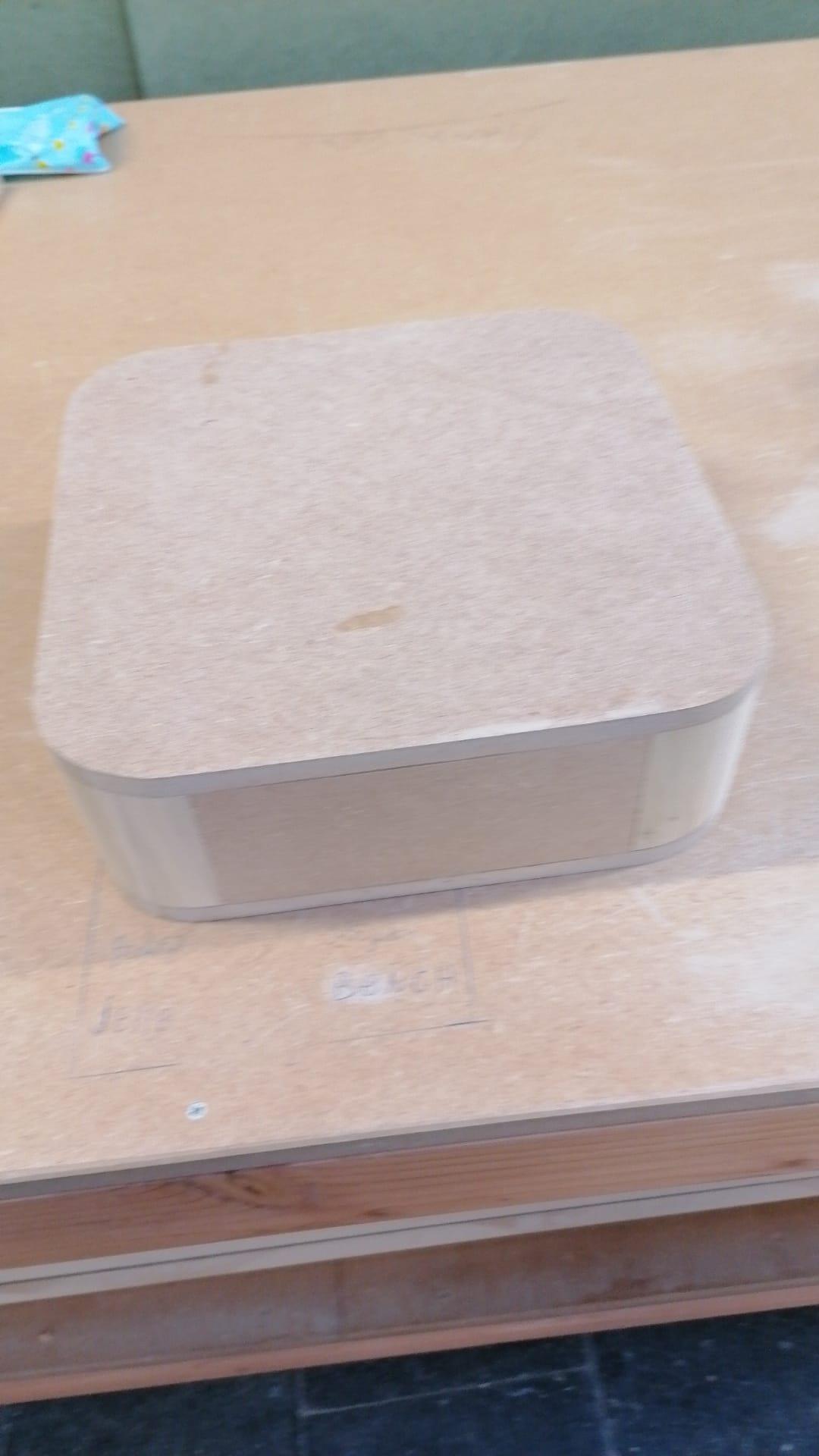
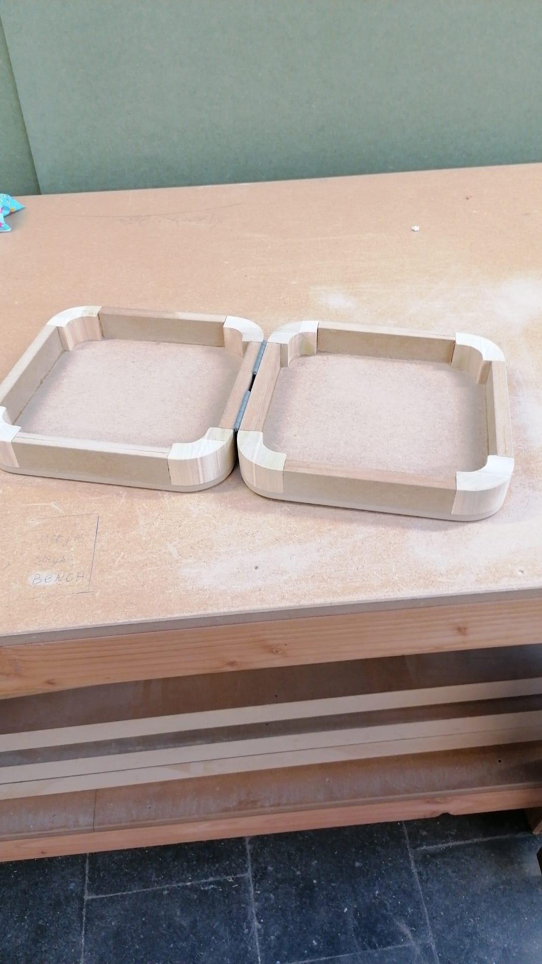
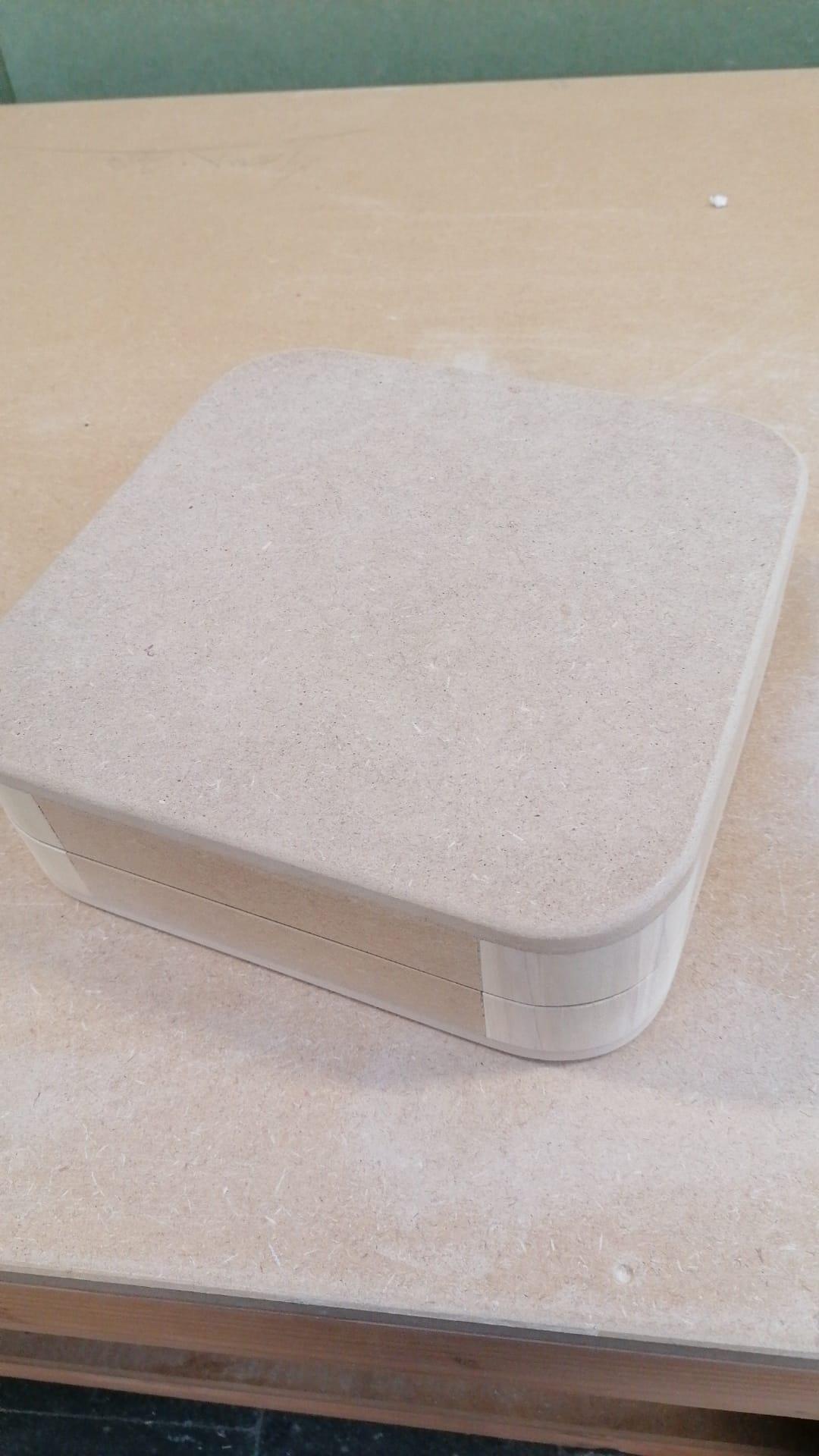
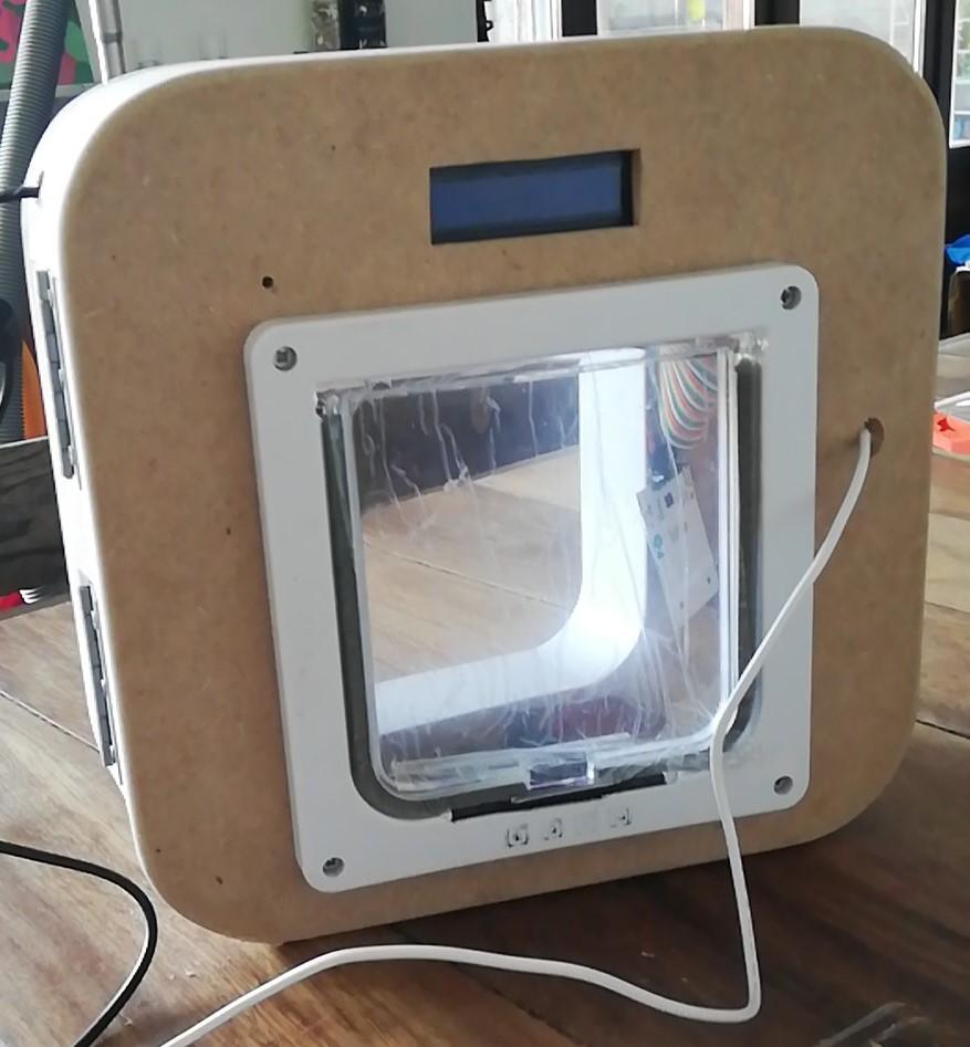
For the case I started with making a sketch in illustrator (first image). The dimensions are 30mm x 30mm x 10mm and it is made completely out of wood. Follow the pictures above to have a similar result as me. You can also choose to make your own design however you like.
Then you have to mesure your components and figure out where you want them. With the help of a jigsaw and a drill you can cut the holes out and put your components in place. All of this is after your own taste, you are totally free to do whatever you want.
Now you can connect your wiring and glue the breadboard and pi on the inside of your case.
I find it usefull to group mij wires by component, for this i use cable ties.
Website
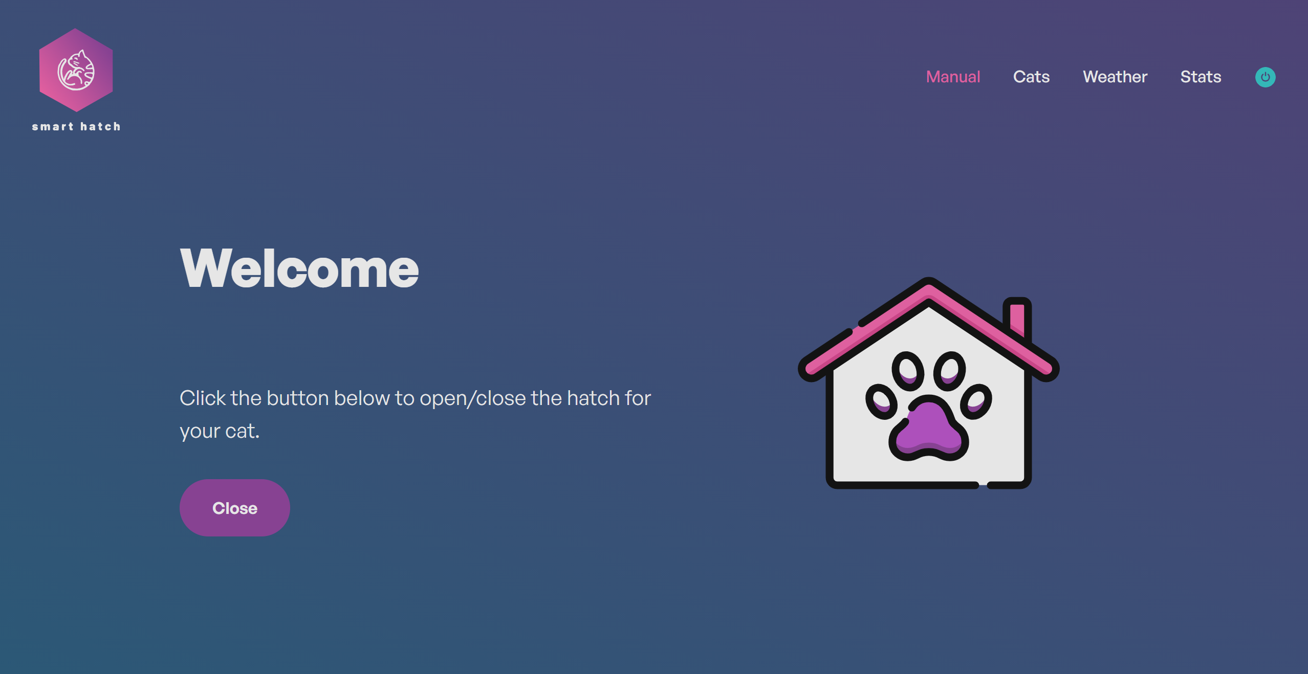
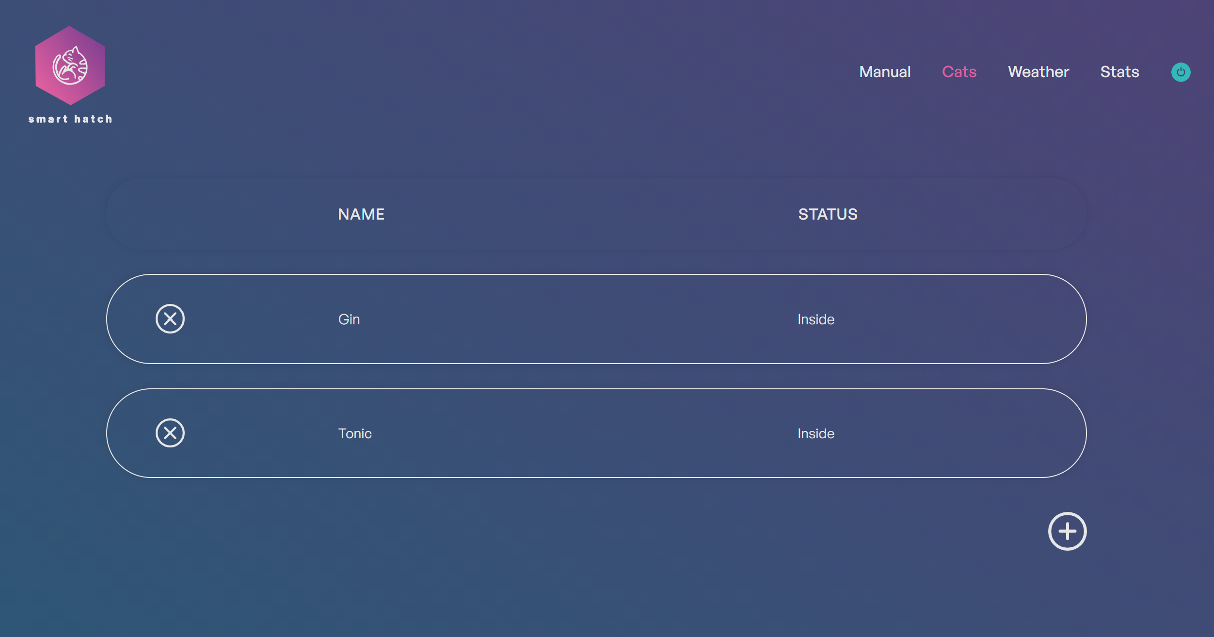
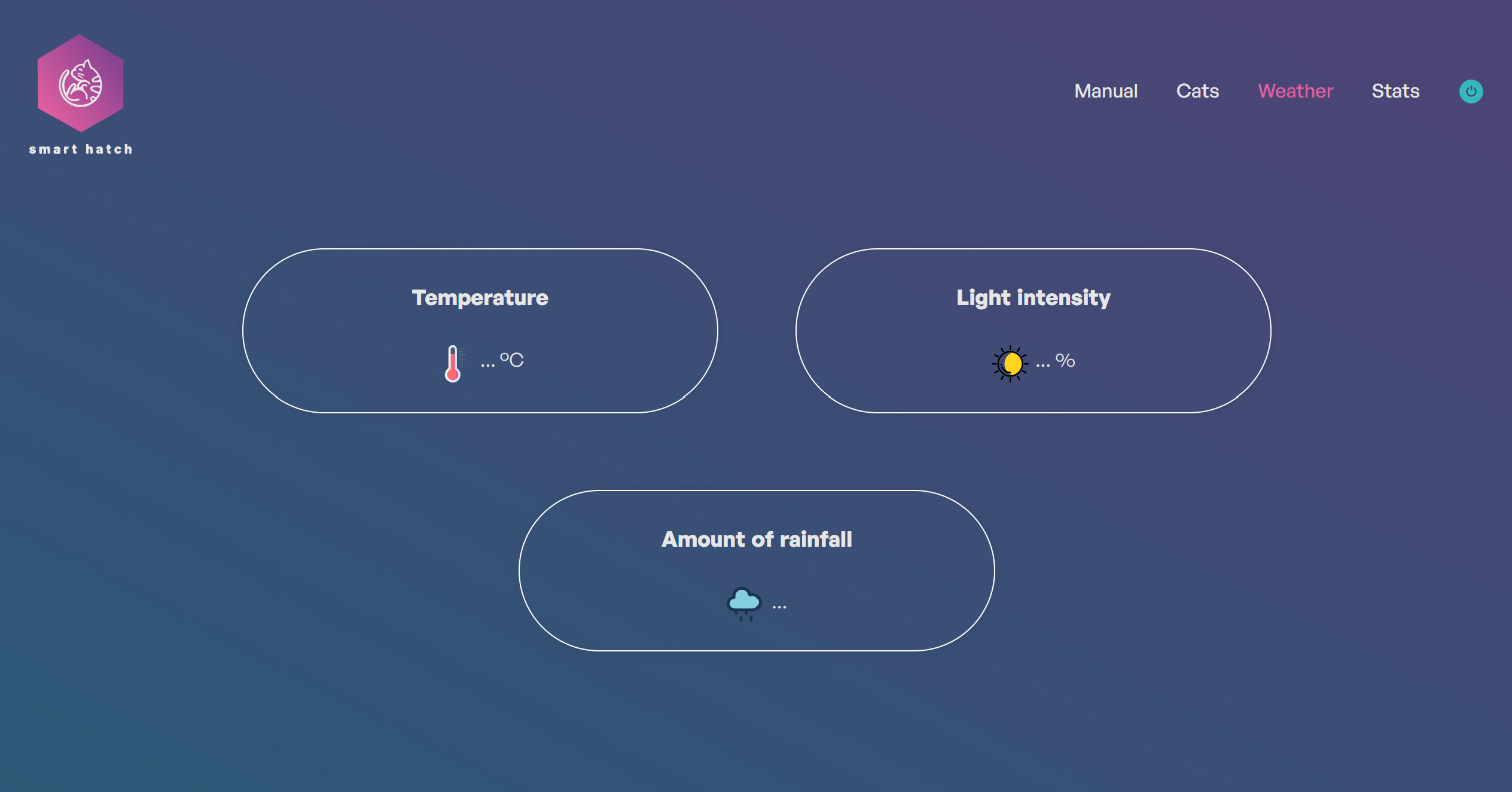
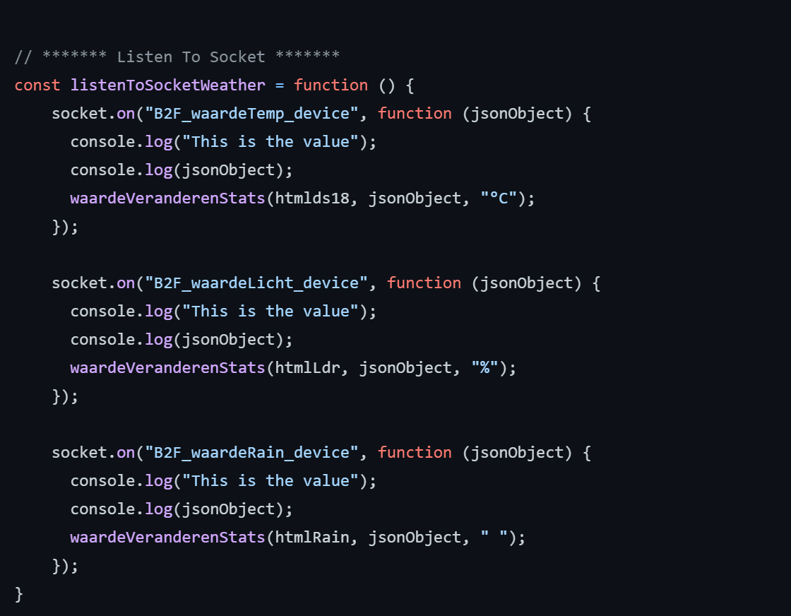
The frontend part was the easiest for me, but for those of you who don't like that at all you can use my link below for the whole design and javascript.
Ofcourse as with the case you can design it however you want to.
With jacascript I made sure that the buttons or data was being proccessed, and you would get the right outputs. There are four different pages Manual, Cats, Weather and Stats as seen on the pictures above.
Configuring SPI and I2C
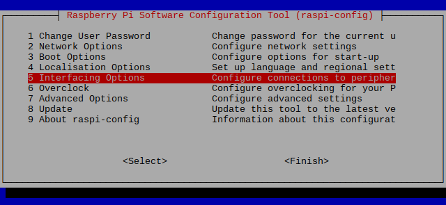
Before we can use the MCP3008, RFID's and LCD we have to enable the SPI and I2C bus.
SPI enable:
sudo raspi-config
5.Interfacing Options
SPI
I2C enable:
sudo raspi-config
5.Interfacing Options
I2C
SPI 1 enable:
sudo nano /boot/config.txt
"dtoverlay=spi1-3cs"
Backend Code
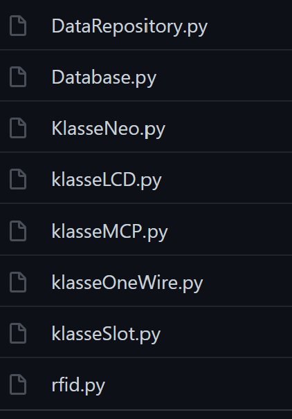
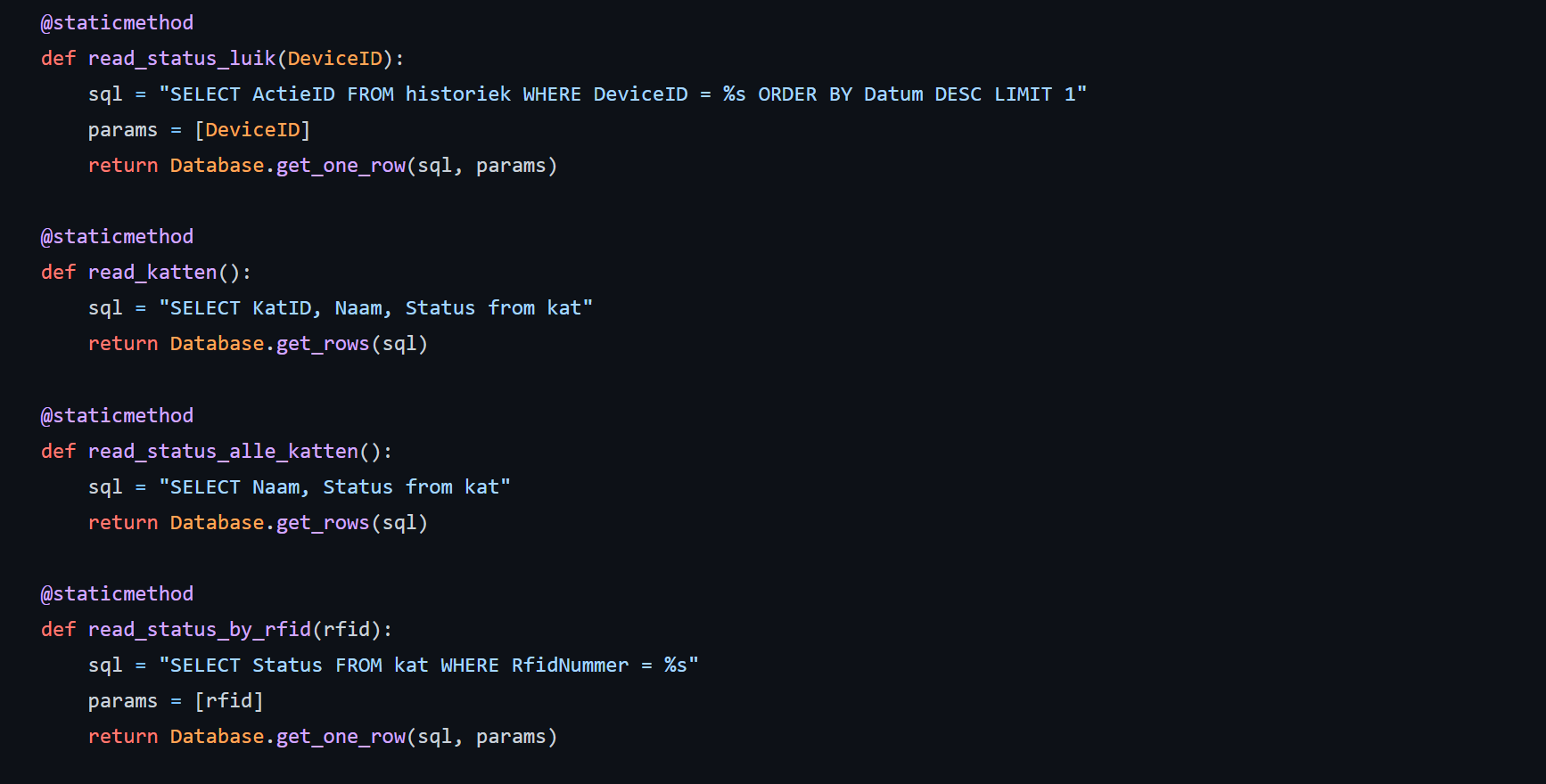
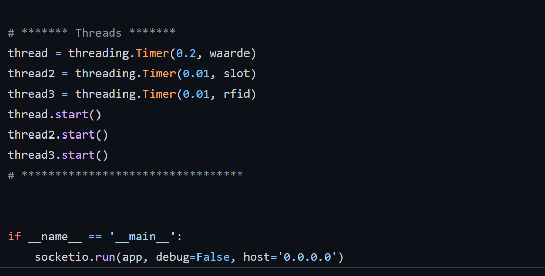
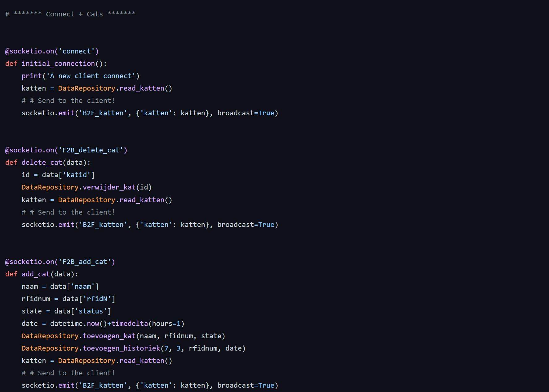
Everything is put together so we can write the code to make the whole thing work!
I started with the stuff that has to be visible on the site, making socketio emit's for javascript to get to work with. Once that was done there came a lot of research about some components like the RFID's. With the use of a couple classes everything fell into place. I find the use of classes very usefull to keep an organized system going.
If you have trouble finding anything in my files start by looking at the commented sections. You can always leave a message under this post aswell.
Here you have the link to the final part of my project: the backend.
I hope you either enjoyed reading or making this, let me know!