Smart Drinking Cup Tracks How Much Water You've Drunk
by JamieFong in Circuits > Raspberry Pi
993 Views, 8 Favorites, 0 Comments
Smart Drinking Cup Tracks How Much Water You've Drunk
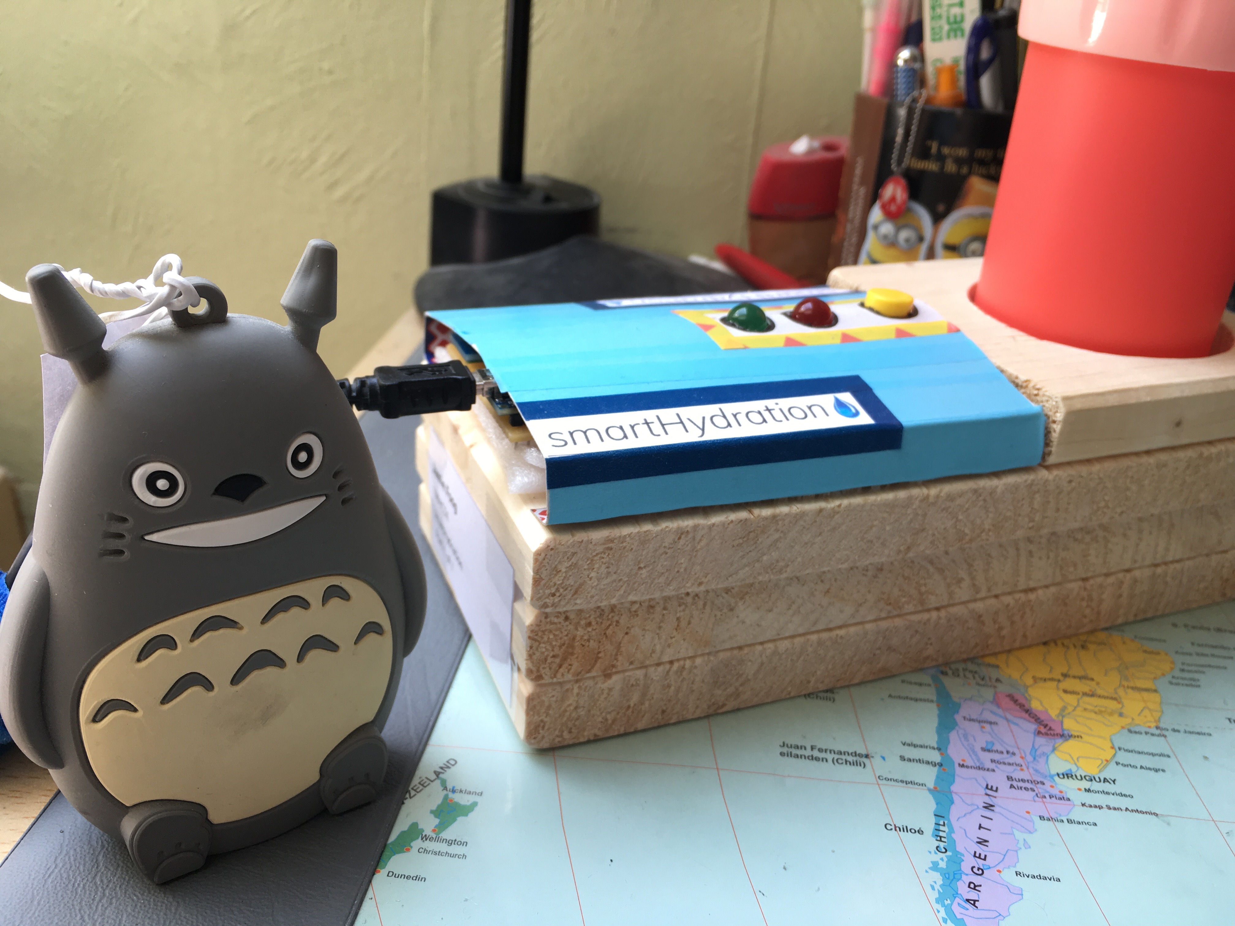
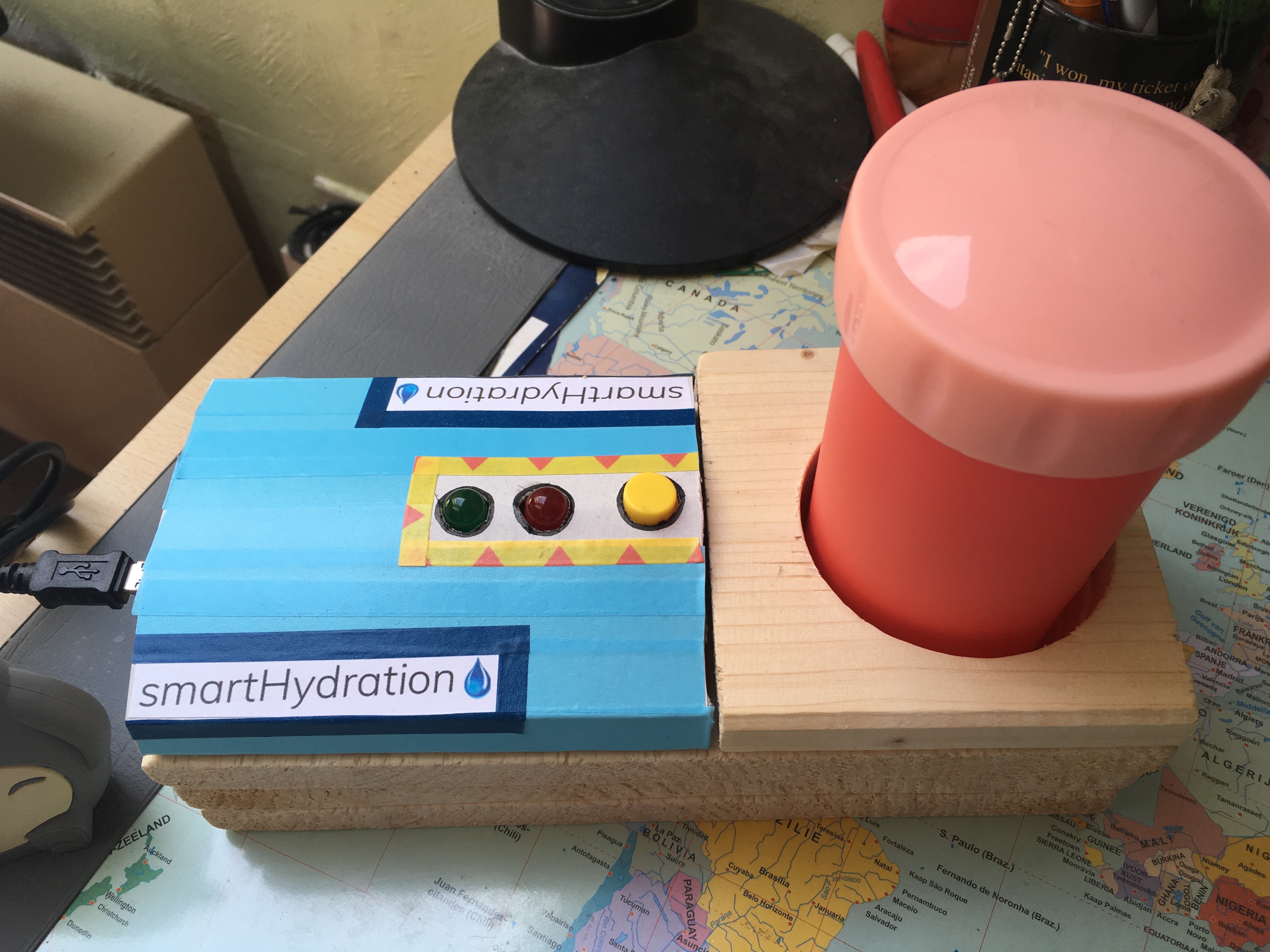
Hi everyone, I'm going to show you how to make a smart drinking cup to track down your daily water intake.
Everybody always tells me I drink too little water. I notice this as well, but for some reason I still don't drink enough. Sometimes I drink maybe one litre a day, which is not good, because you're supposed to drink at least 1,5 litres of water.
When we had to choose a project for school I scanned the list of examples for potential projects. I saw 'smart drinking cup' and that gave me an idea to create something to track how much a person drinks water. So I started this project.
In this instructable I'm going to share my work process in several steps to show how I did it.
Things You Will Need
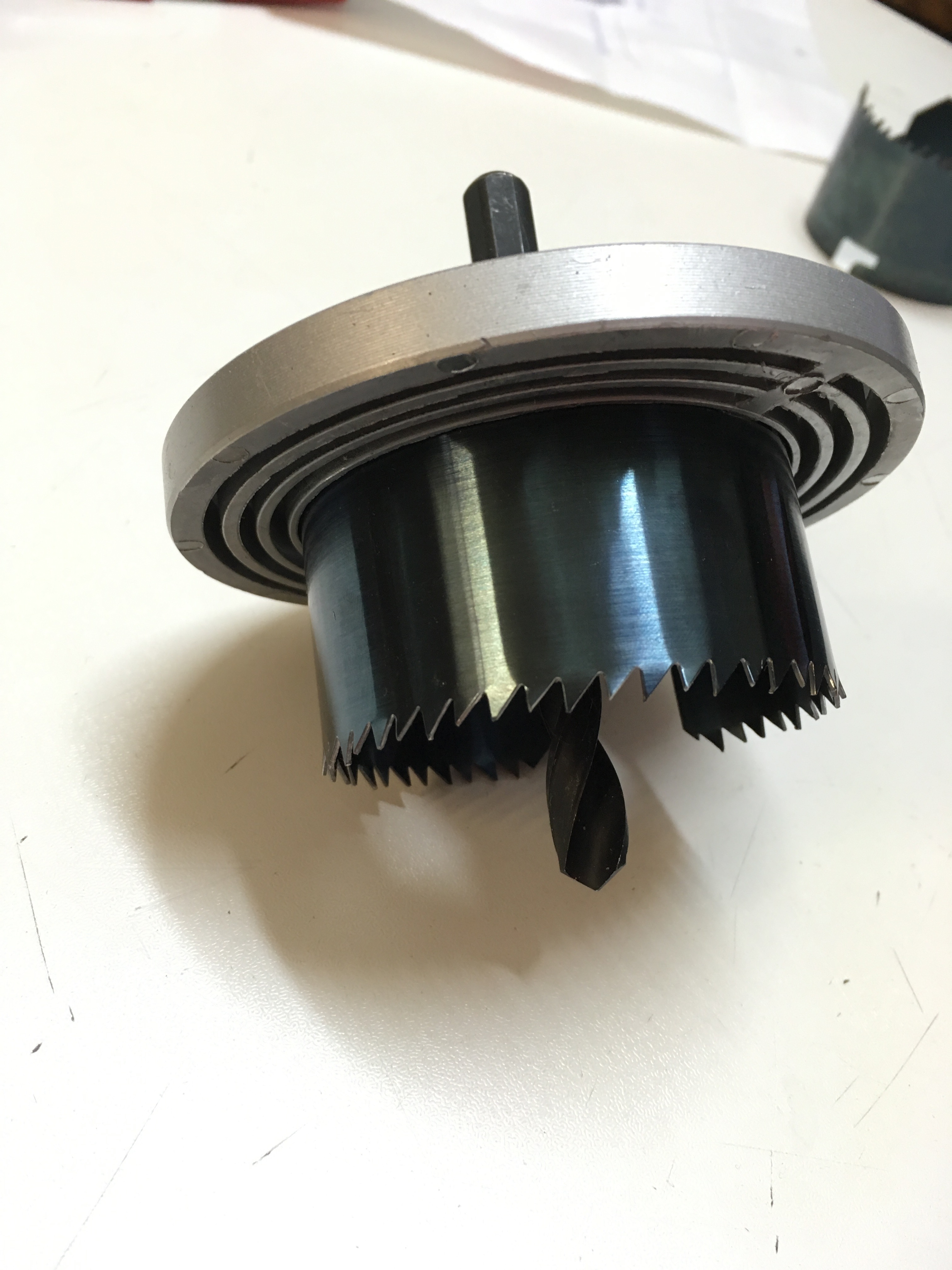

Tools:
- Hole saw
- Saw
- Drill
- Sandpaper
- Regular glue
- Wood glue
- Utility knife
- Soldering iron + tin
Material:
- Drinking cup (I chose one with a diameter of 6 cm and with a volume of 320 ml)
- Wooden plank (at least 40 cm long and 30 cm wide)
- Thin carton (for example: cereal box)
- PCB
- Washi tape (decoration)
- Powerbank (with an output of 5V)
- Arduino Nano
- Raspberry Pi (3 model B)
- Ethernet cable
- Raspberry Pi power supply (USB -> micro USB cable)
- Breadboard
- Bluetooth module HC-05
- Mini USB cable (Arduino Nano power supply)
- Two LEDs (red and green)
- Jumper wires (male - male)
- Three resistors (330 ohm)
- Button
I've added a Bill of Materials in the attachments. The total sum is €118,92. The price can be different for every person. If you already have a e.g. Raspberry Pi, you don't have to purchase this again of course.
Downloads
Fritzing Layout and Database Model
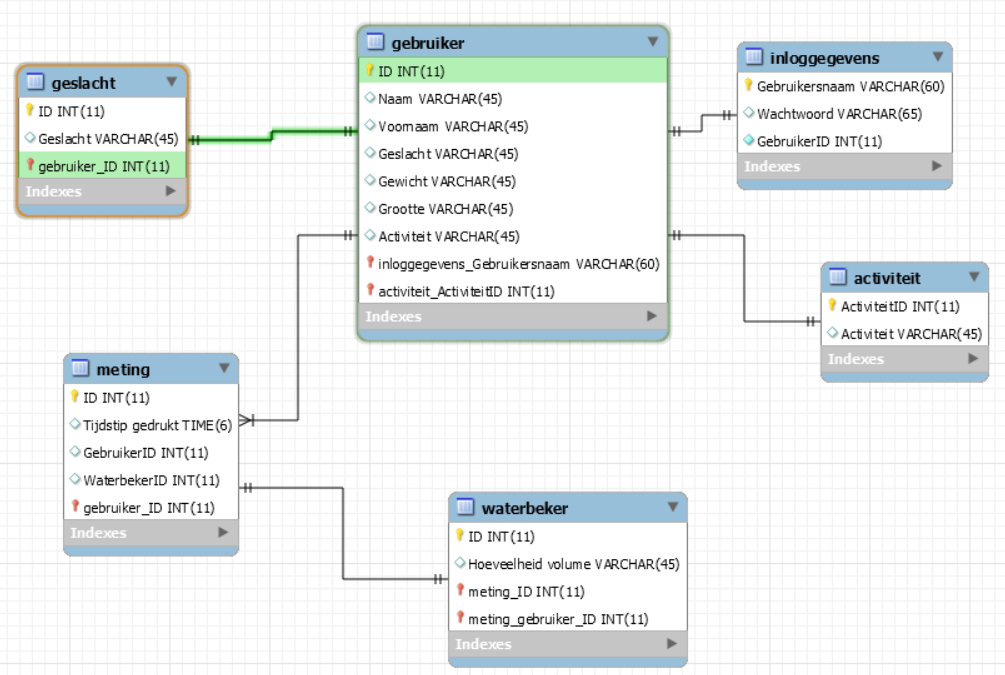
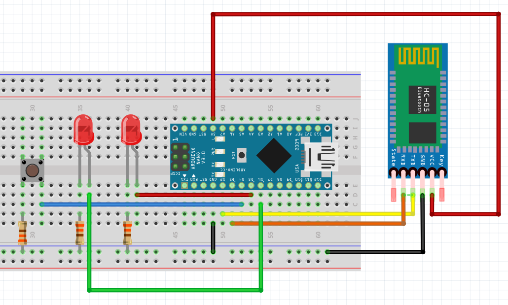
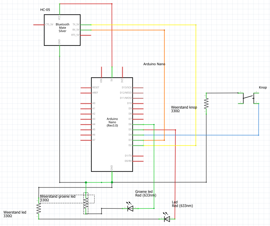
First, you have to make a normalised database model to determine the logical structure of a database and also determines in which manner data can be stored, organized and manipulated. My database model can be seen in this step. Set some example data in the database (e.g. datetime).
Next up, you need to know how you're going to connect your components with the Arduino Nano. I made a fritzing layout (in breadbeard and in scheme), I've included these two in this step.
Most components are connected to the Arduino Nano to a digital pin. I don't use the analog pins. Keep in mind that the button and the two LEDs need a resistor of 330 ohm (and connected to the ground).
Connecting the Components to the Arduino Nano
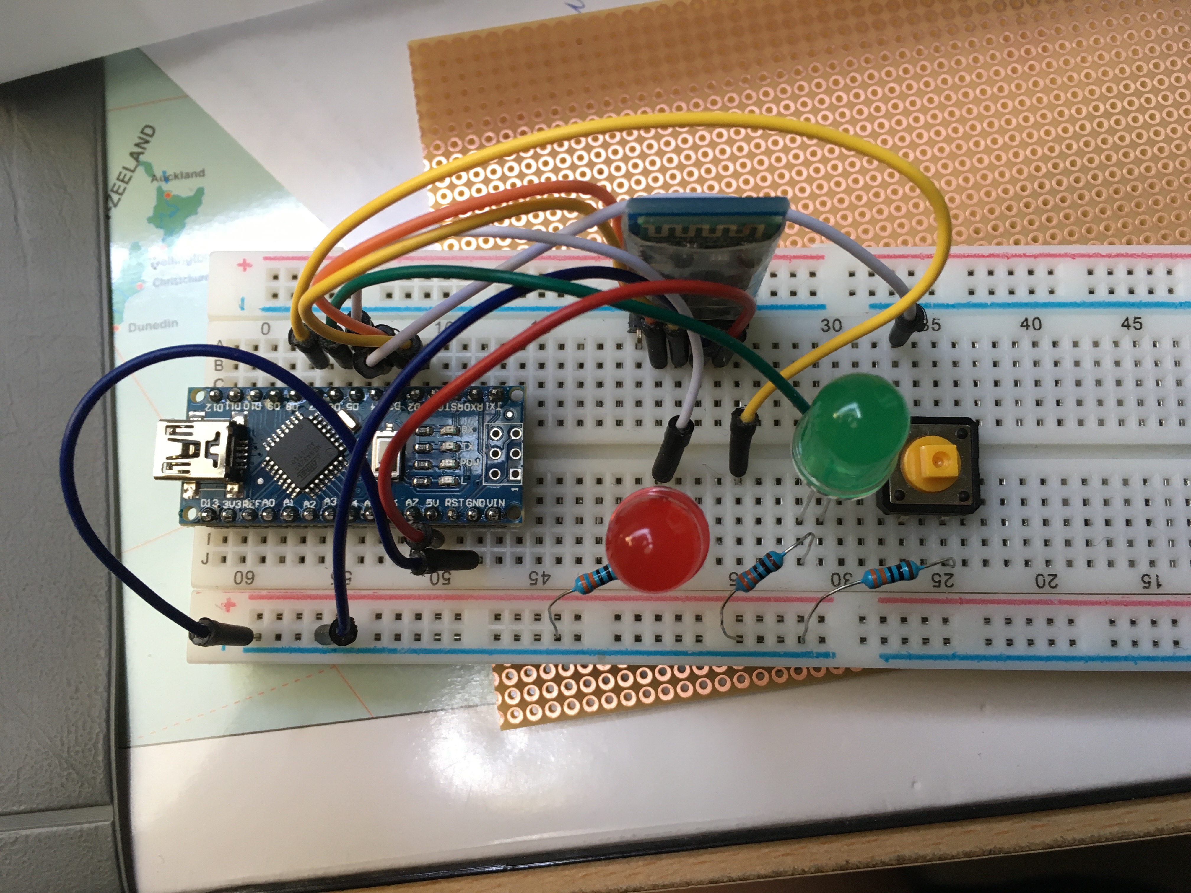
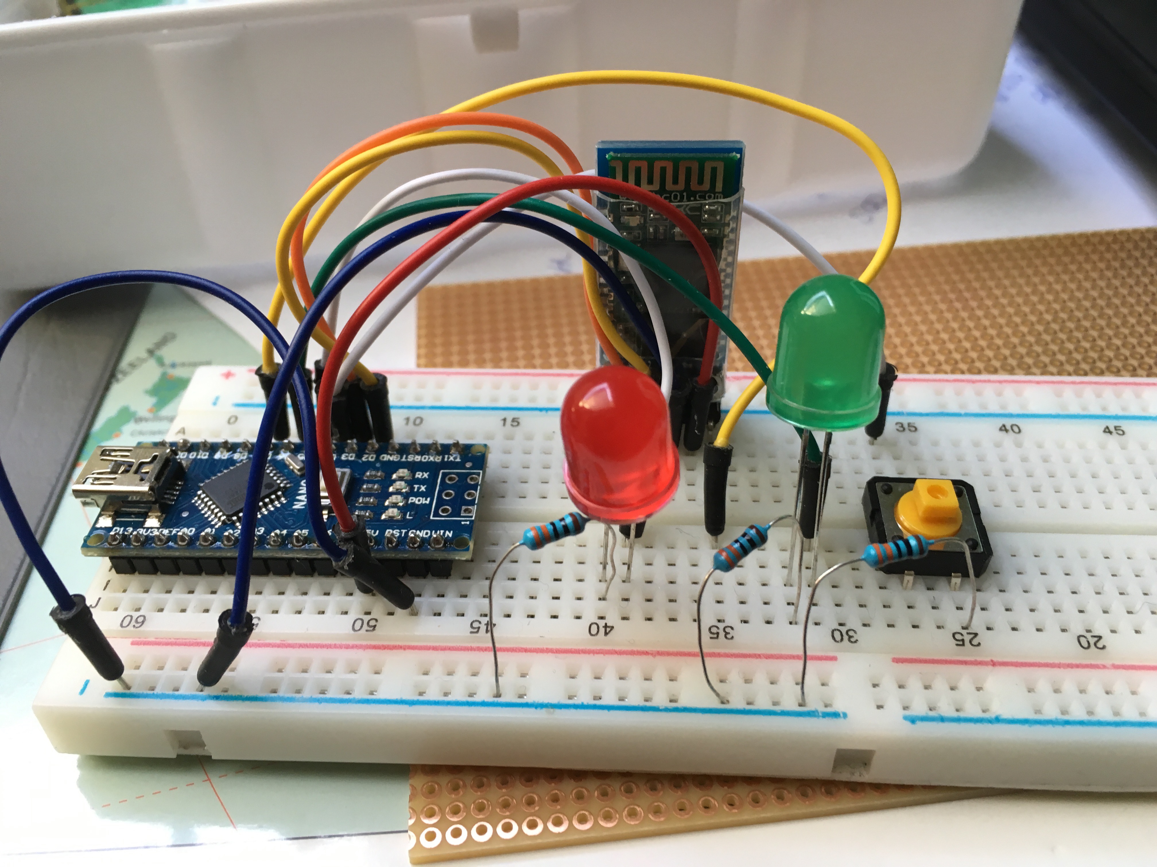
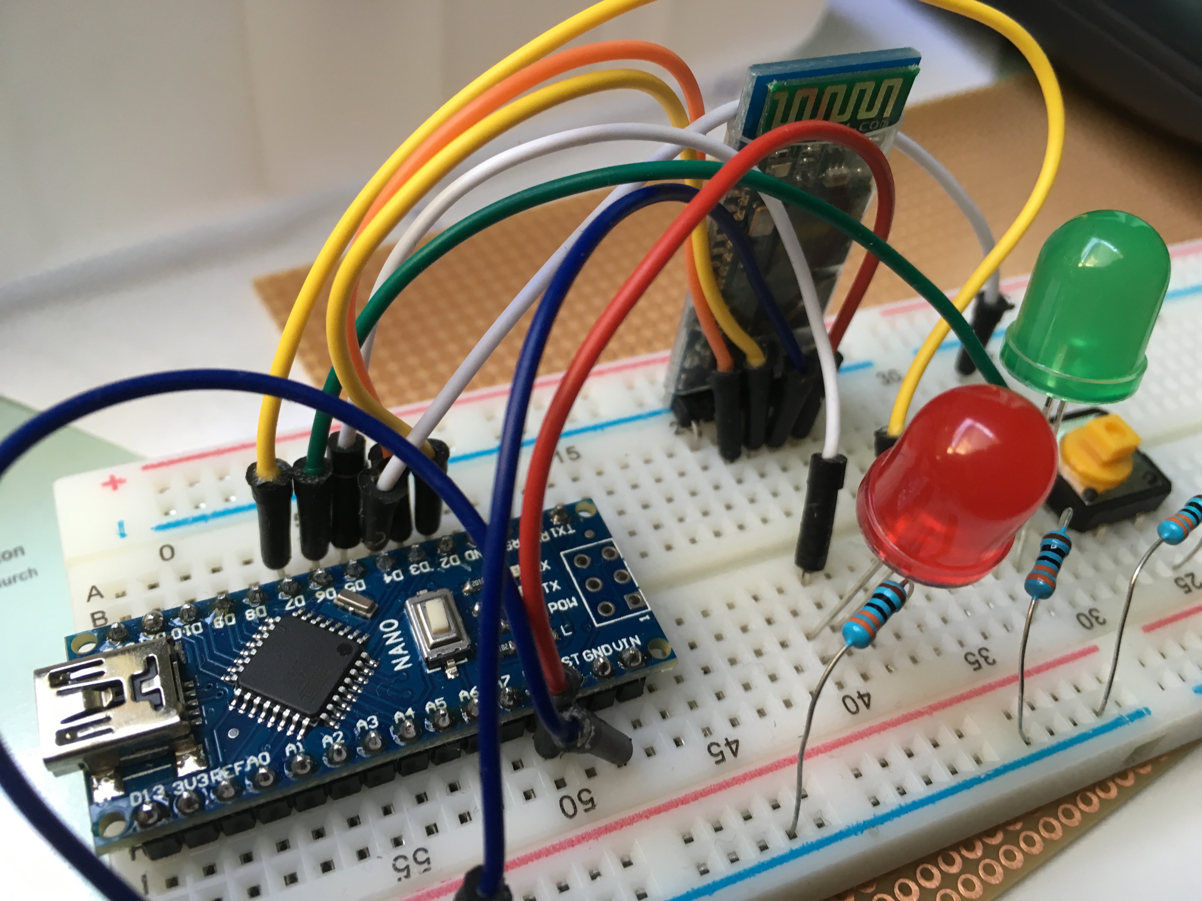
With the help of my fritzing layout I made earlier, I made this electronical circuit. Make sure everything is correctly connected, otherwise there will be a short circuit.
You can test if you've connected it correctly with my code.
Click HERE to see the Arduino code.
If a LED turns on when you push on the button, that means you've done it correctly!
The link to my GitHub repository (all code): https://github.com/JamieFong/Project1
Connecting the HC-05 to the Raspberry Pi
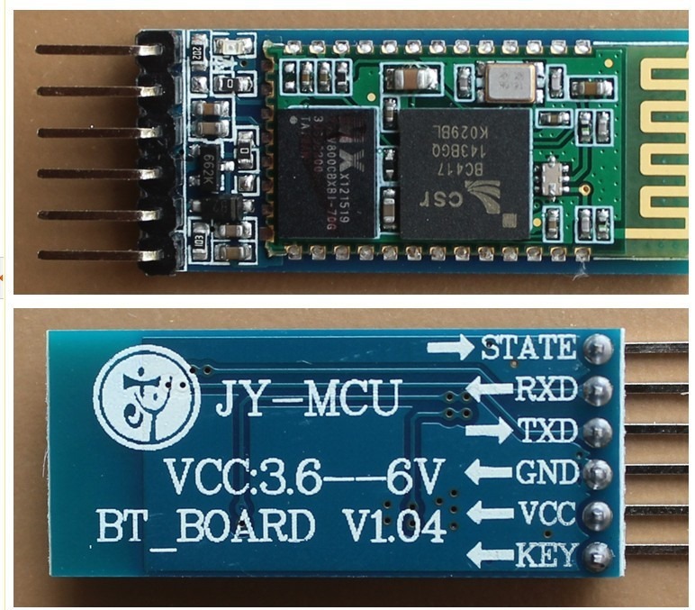
Connecting the HC-05 to the Raspberry Pi was the hardes part of this project. The HC-05 would pair with the Raspberry Pi but wouldn't connect with it. Or it would be connected for like 3 seconds and then it would say it's not connected again.
After hours of looking on the world wide web, I found something (together with the help of a teacher) to connect the HC-05 with the Raspberry Pi.
Open the terminal on the Raspberry Pi to connect with the HC-05 that is connected to the Arduino Nano and type this command to see what address the HC-05 has:
hcitool scan
After a minute of scanning, it will show you the name of the module (HC-05) and its address.
To connect with the HC-05 you'll need the address from your own controller, to find out what your controller's address is type:
sudo bluetoothctl
You'll see your address on the first line that comes up followed by your Pi's hostname.
Now that you know these two addresses you can connect the Raspberry Pi with the HC-05. To do this, type this command:
sudo rfcomm connect AA:AA:AA:AA:AA:AA BB:BB:BB:BB:BB:BB (with AA:AA:AA:AA:AA:AA being your controller's address and BB:BB:BB:BB:BB:BB being the address of the HC-05)
Normally, you would see that the two devices are connected with each other. To end the connection, you can press Ctrl+C.
How to Set the RPI That It Knows When the User Presses the Button


Because of this connection, it's created a new text file in the directory /dev/ , rfcomm0 has been added to the directory.
As you've maybe seen in the code, every time someone presses the button, it will send a "k" to the RPI (BTSerial.println). This "k" will appear in the new file /dev/rfcomm0. If you open the file and you press on the button, you'll see a "k" appearing. (Note: I use multiple sessions in PuTTY, I use one session for the connection and one to check de rfcomm0 file to see if the bluetooth connection works).
Also, this code BTserial.write(10); means that it will be send to the RPI. The '10' stands for new line (in decimal) in the ascii table. So this can be compared to pressing the Enter button on your keyboard.
So now we can write code that does something every time the Raspberry Pi receives a "k". (Note: I just randomly chose the letter 'k', if you want to use a word or a sentence, you can).
Install MySQL on the Raspberry Pi
If you want to collect the data, you should have a database management system. I chose MySQL.
First off, you'll have to make sure all the updates and upgrades are installed on your Raspberry Pi. Use the following command:
sudo apt-get update && sudo apt-get upgrade
(Note that it can take a while to upgrade)
Next up, install the MySQL server on the Raspberry Pi:
sudo apt-get install mysql-server (Password is needed)
To connect with the database you'll need a client. Install the mysql-client with the following command:
sudo apt-get install mysql-client
You'll connect with the database with the root user. The root user will be in complete control over the database. Connect with the database with this command:
mysql -uroot -p
Now you're in the MySQL monitor!
So finally, the last thing to do is to make a Python connection with the MySQL database. For that we need a MySQL connector.
sudo apt-get install python3-mysql.connector (Password is needed)
Install Flask
The webserver I'm using is Flask. To install this, type the following command:
sudo apt-get install python3-flask
Set Data to Database
Now on to the Python code.
I have one main python script to read the /dev/rfcomm0 if the file receives a "k" or not. The idea is to set the current time to the database (so you'll have an entry log of when you pressed the button).
Other than this main python script, I made a database class, to connect with the database and to set data to the database and to get data from the database. In this class I made a function with a query in it to set the current datetime to the database (Code database in link "database class").
If the function is done, you'll have to import the database class into the main python script (to read the file) and then you'll have to make a class object and after this you can use the function with the query to set the current datetime to the database (this function can be used in another function in that main python script).
The Website
You can find the code to the website here. (Note: the website is in Dutch, not in English).
You'll see that (if you can read Dutch) there's a page to log in and to register. I've never learned how to do this in school so I can't really log in and register on this website. It's there, but it's basically useless.
On this website, I use the database class to get the data from the database to post on the website. I also can change the settings with the UPDATE statement in a query in a function in the database class.
For the rest, it's all just basic HTML and CSS (most of it retrieved from our school platform).
The Housing (PCB)
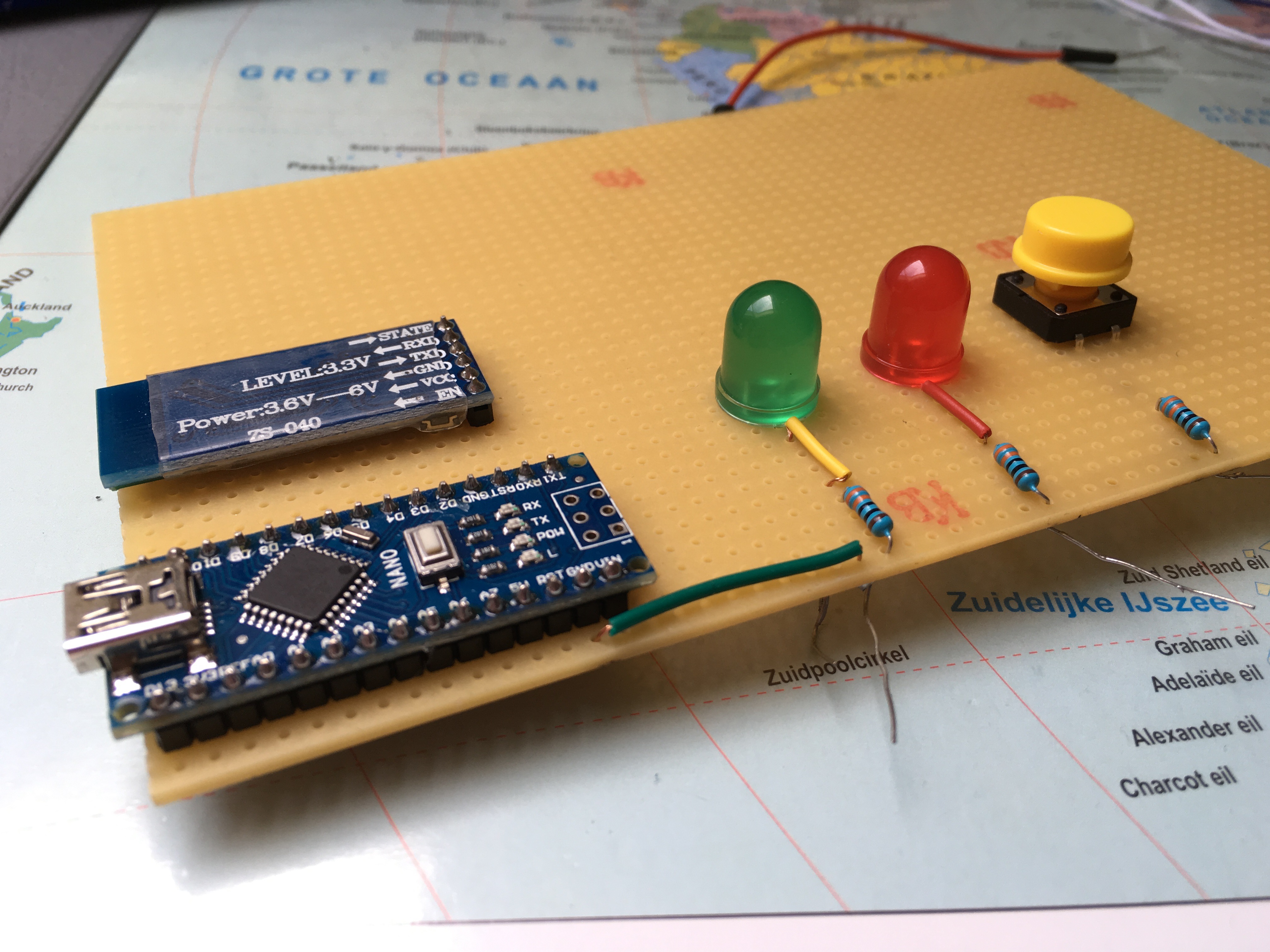
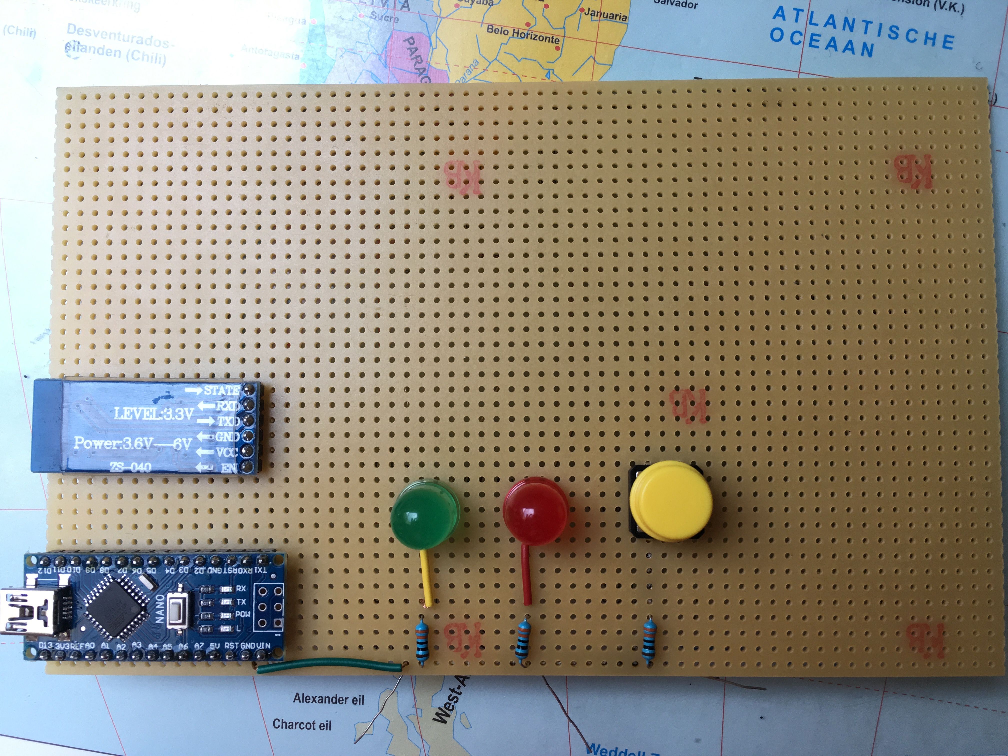
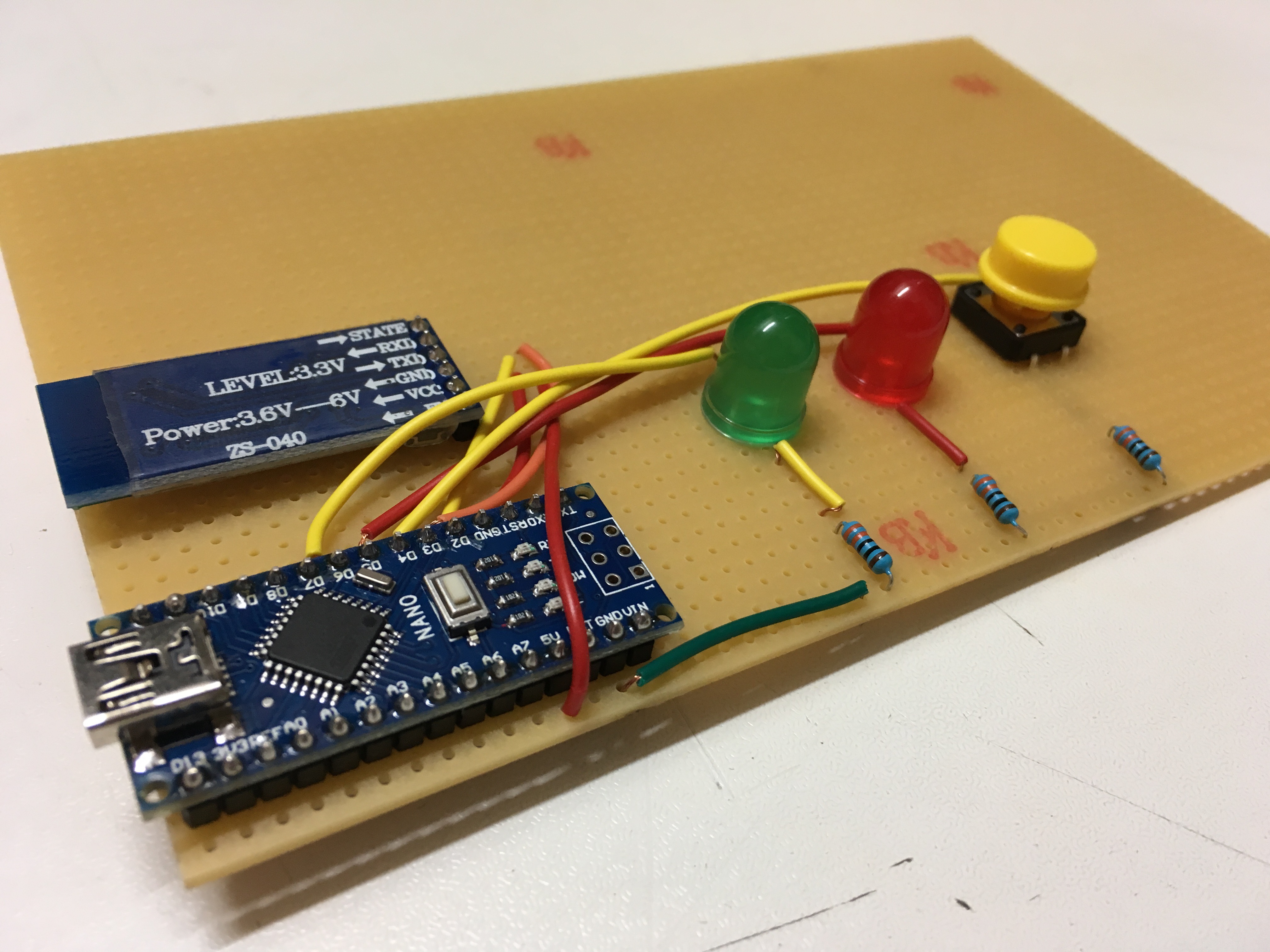
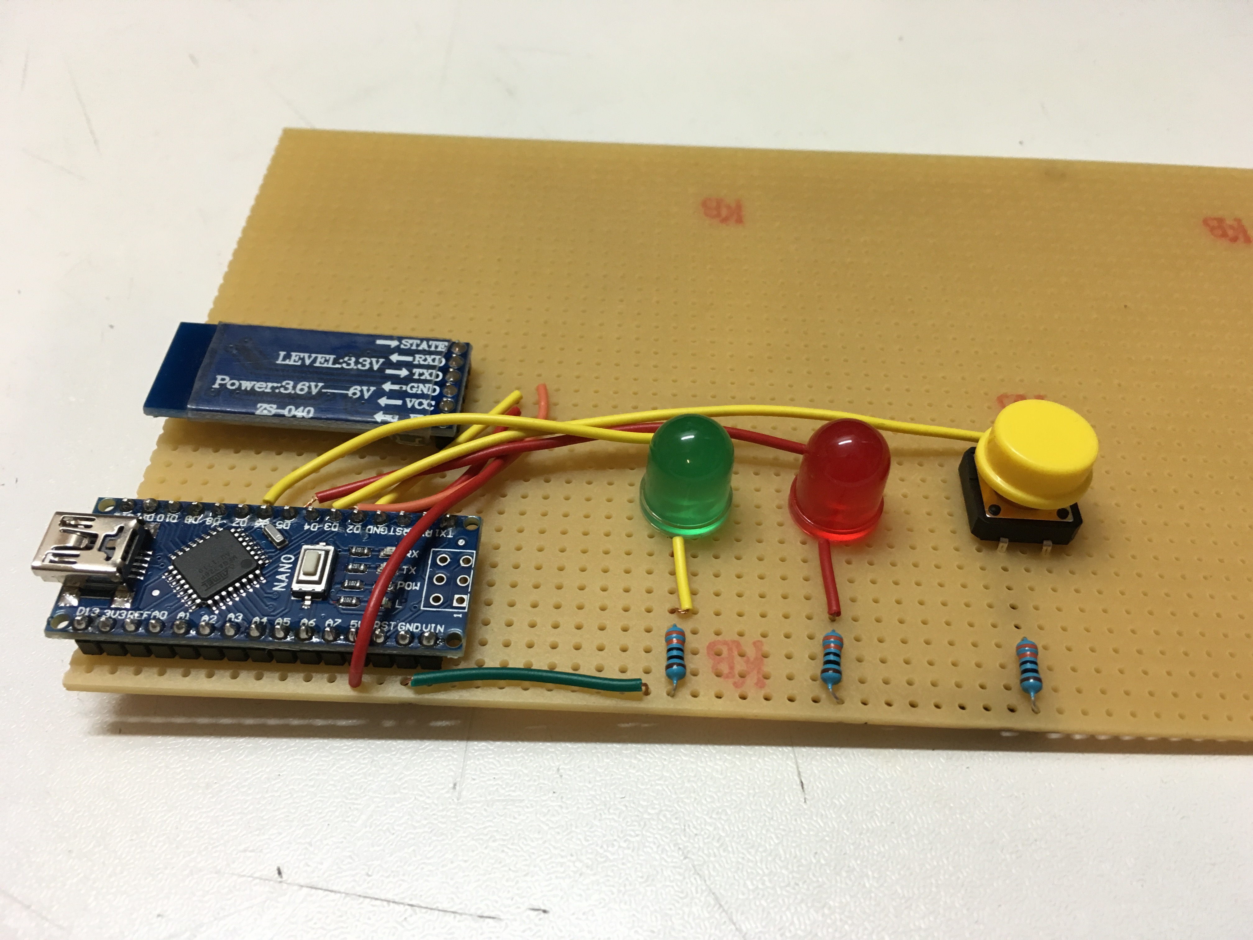
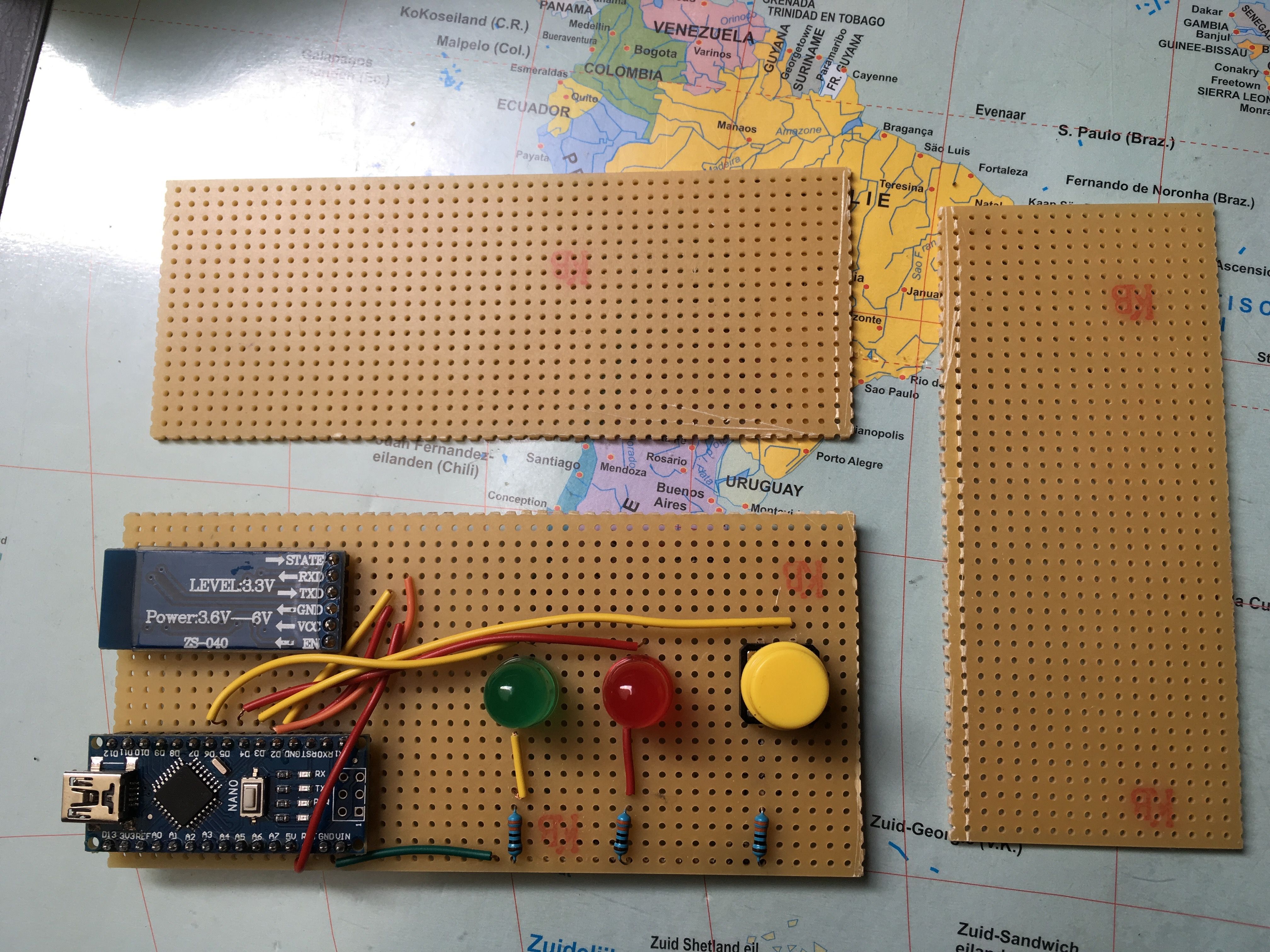
If everything electronic is done, we can start with the housing!
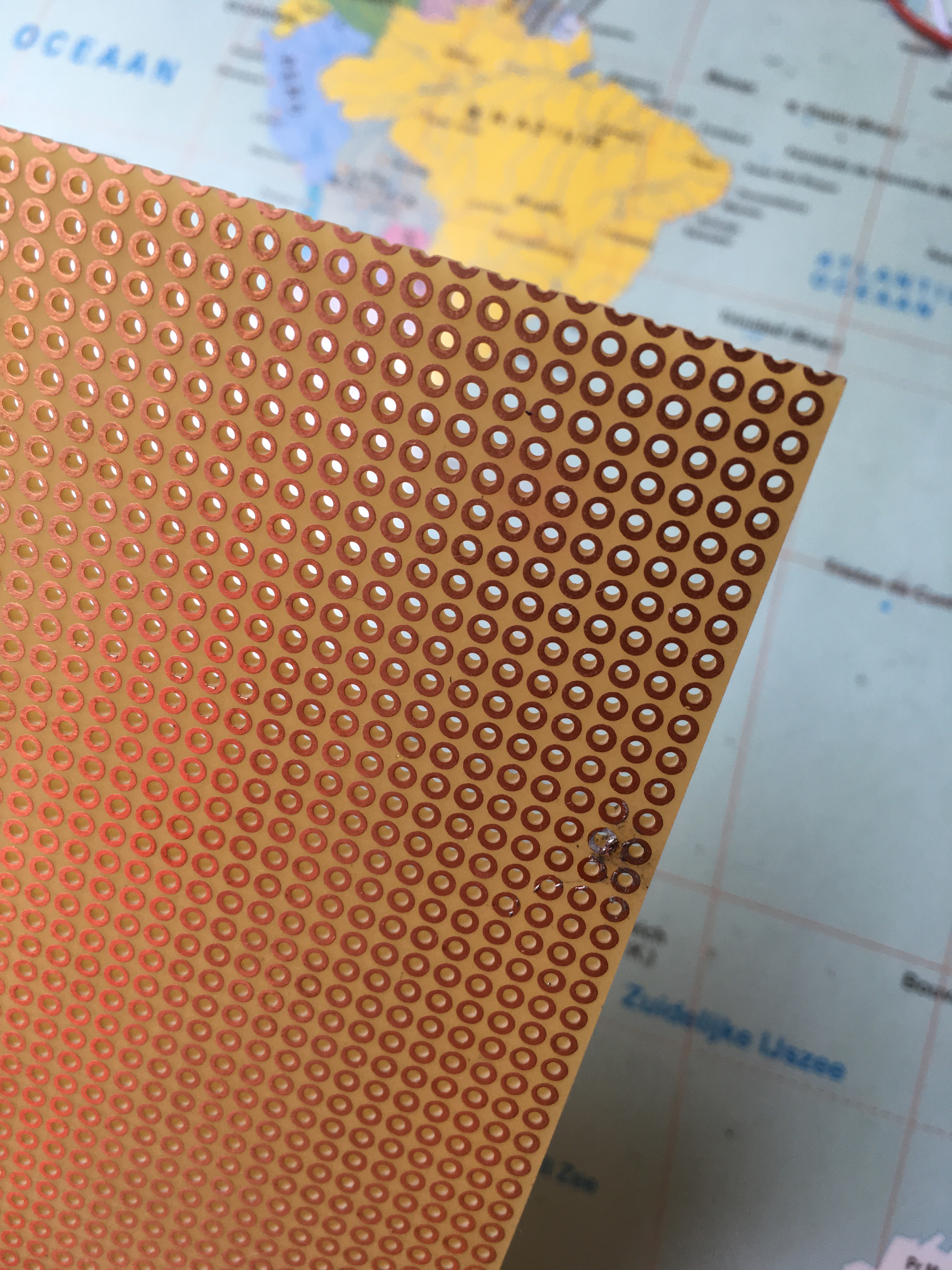
First, you're going to solder the components on a PCB, so you won't have to use the breadboard anymore with all the jumper wires. Make sure the connections are the same as in the circuit on the breadboard and that you don't have a short circuit. You can test if you've done the connections correctly by using a multimeter and set it on the buzzer mode.
If the PCB is too big, you can use a utility knife to cut it, but you won't be able to cut entirely through the PCB. Use the utility knife so you have a lot of scratches so you can easily crack the PCB in pieces. (Note: I'm not the best in soldering, this was my first time soldering on a PCB).
The Wooden Housing
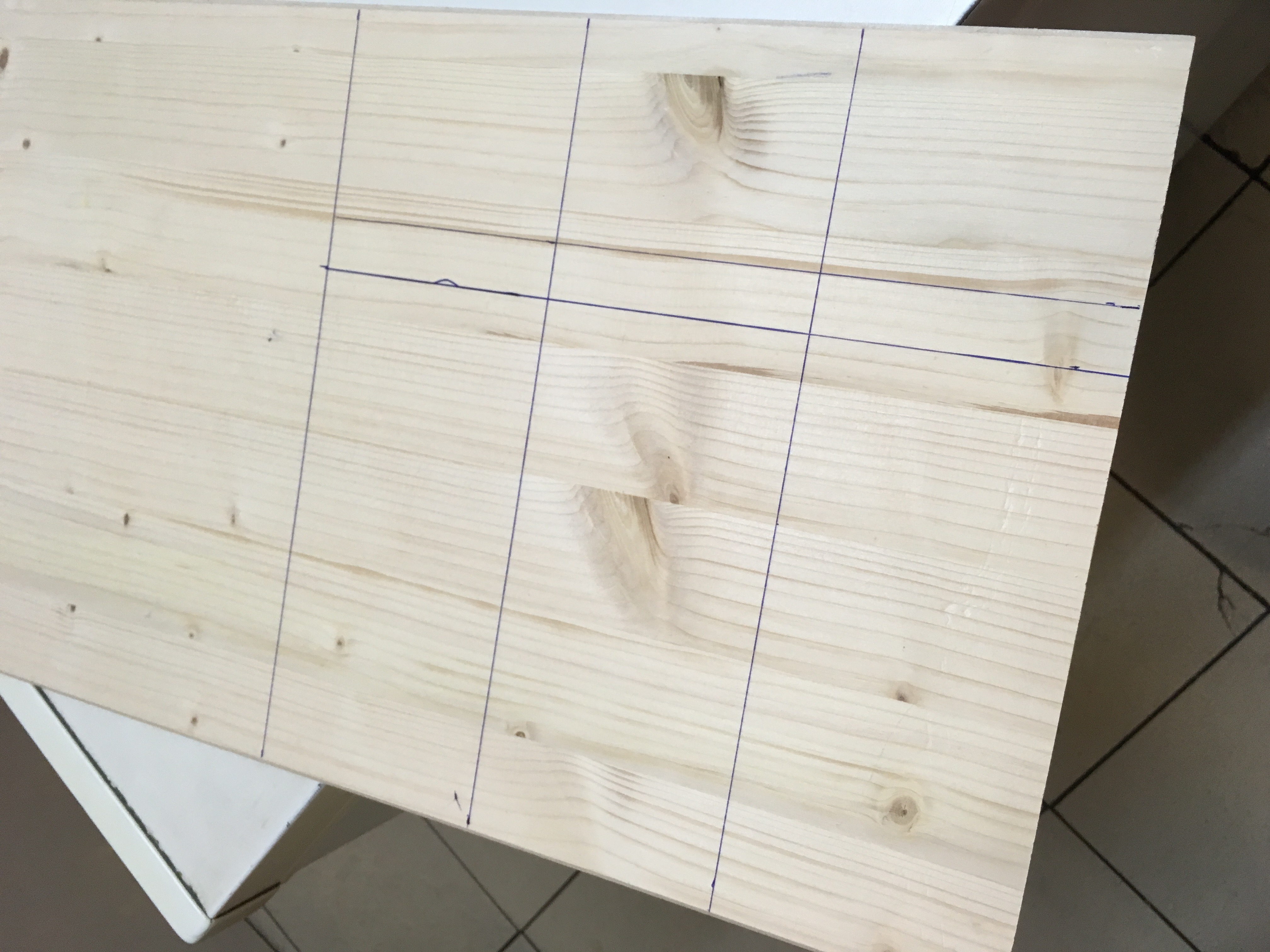
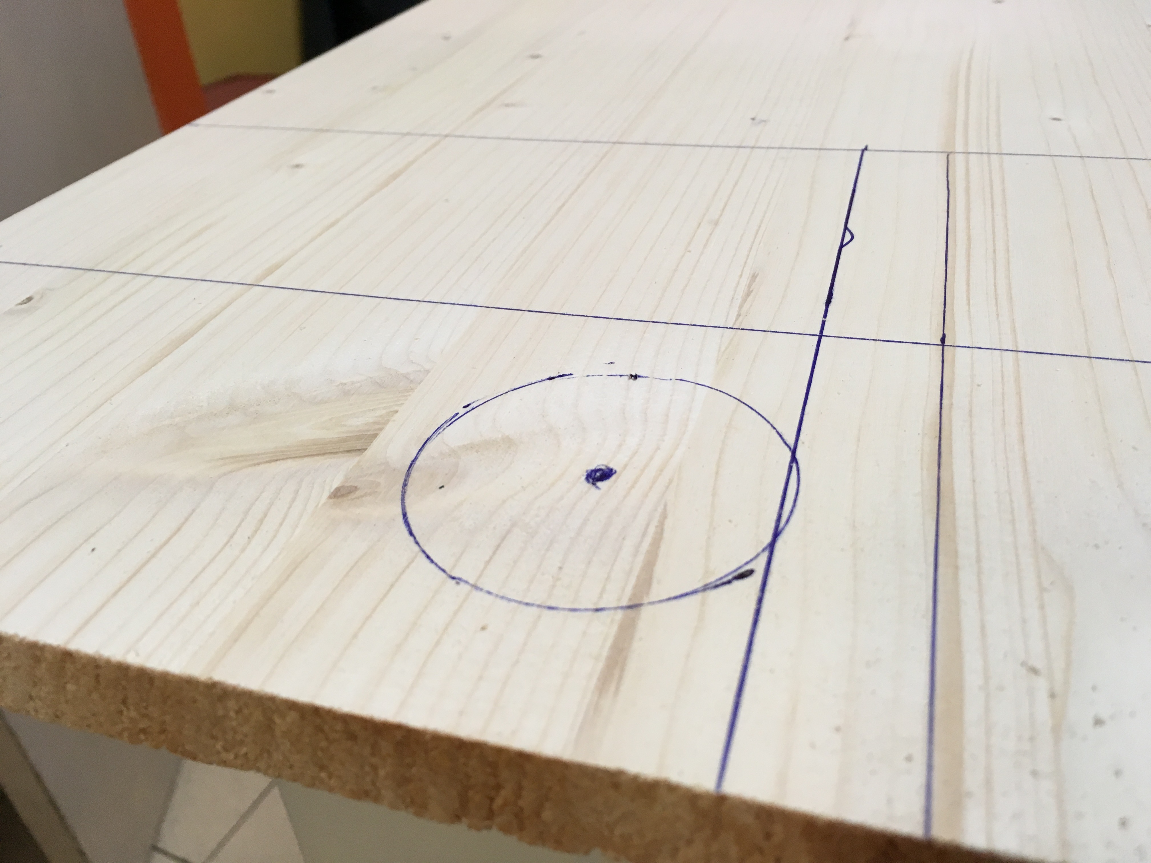
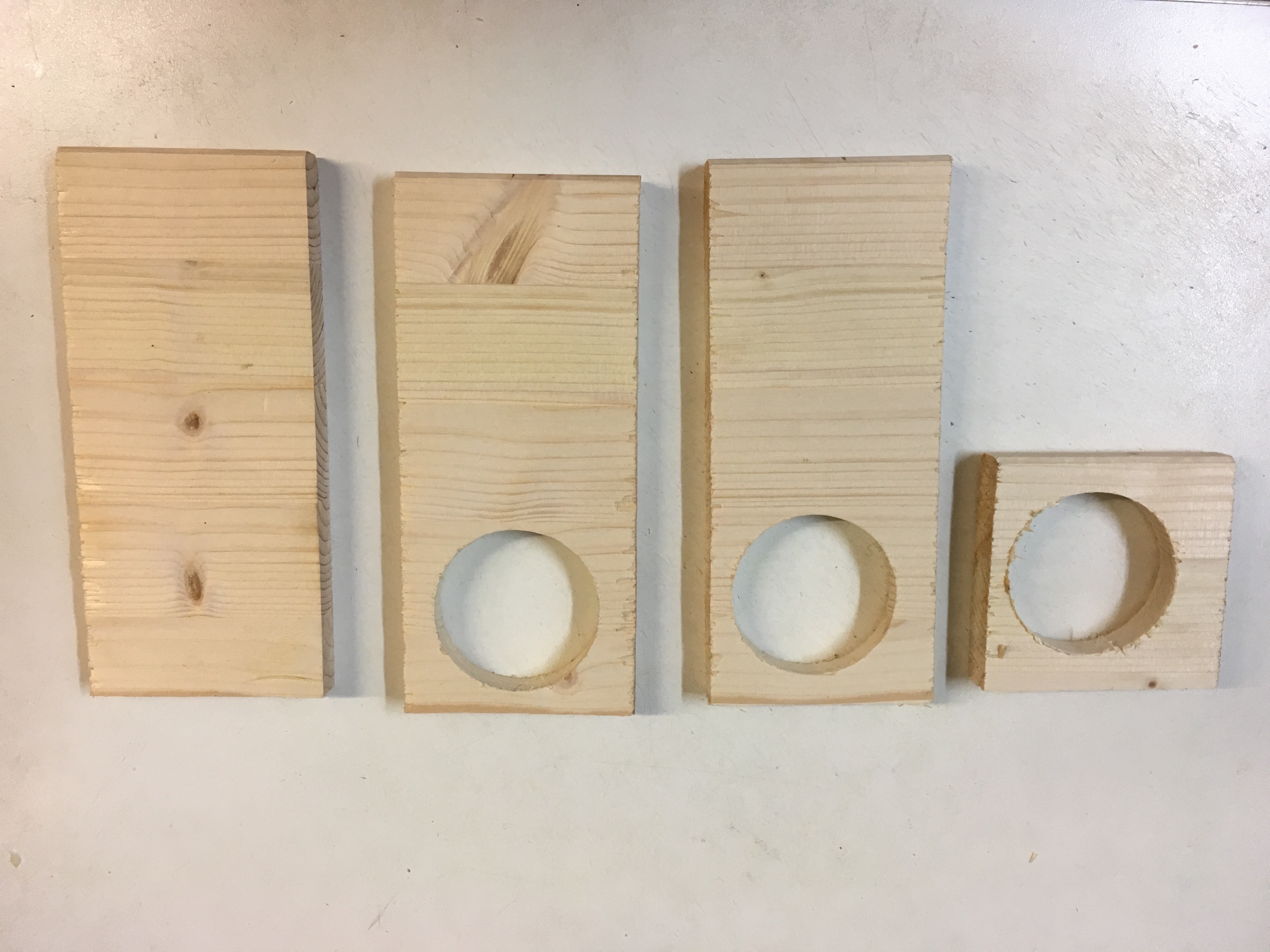
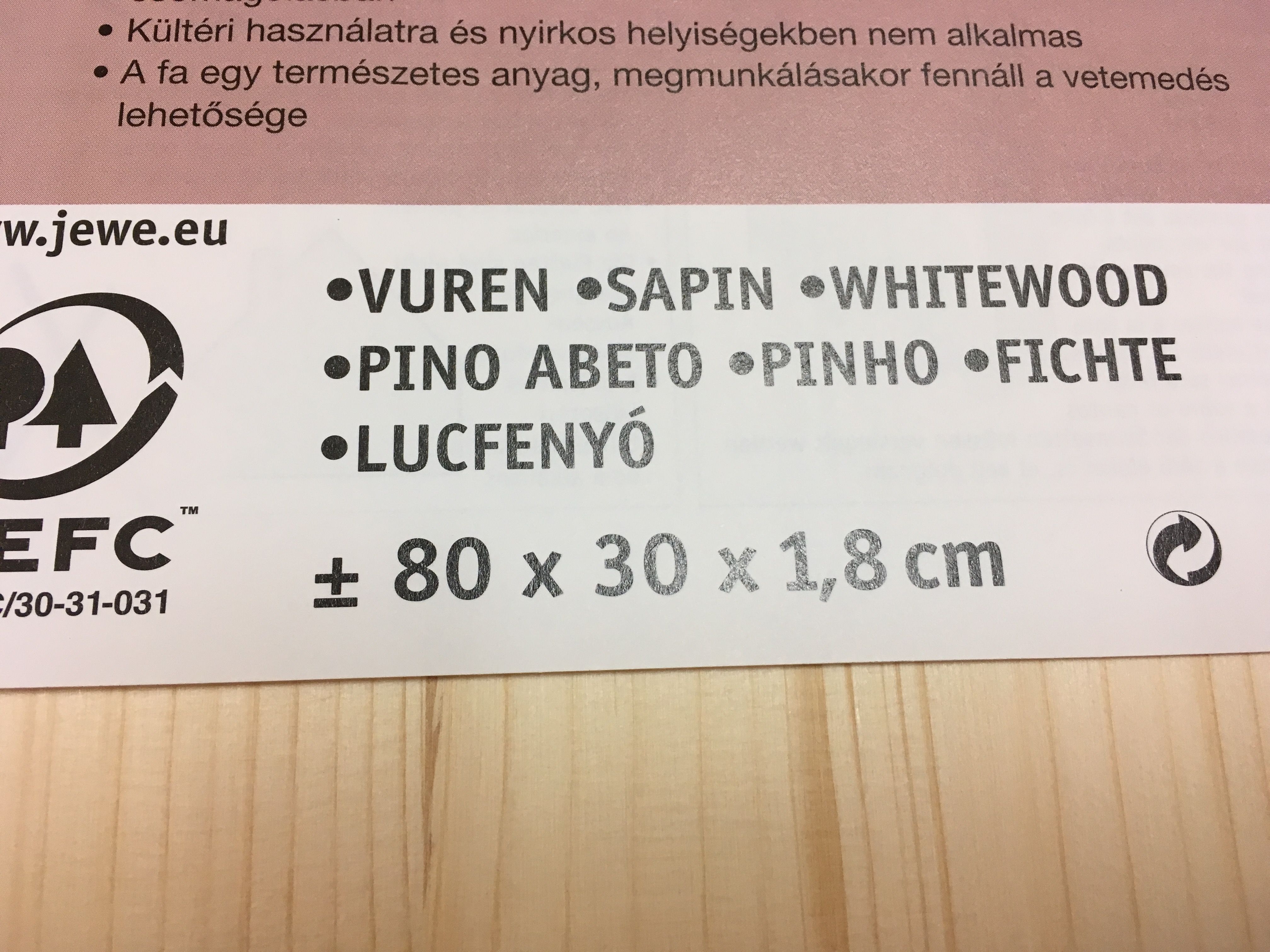
For the wooden housing I used whitewood (80 x 30 x 1,8 cm). I have marked the wood so that the length is 22 cm and the width is 9,5 cm. (Note: these measurements are for my 6-diameter-drinking-cup, so if you're drinking cup is larger in diameter, you should increase the width). I've also marked my circle, this is where the cup should be placed in the cupholder.
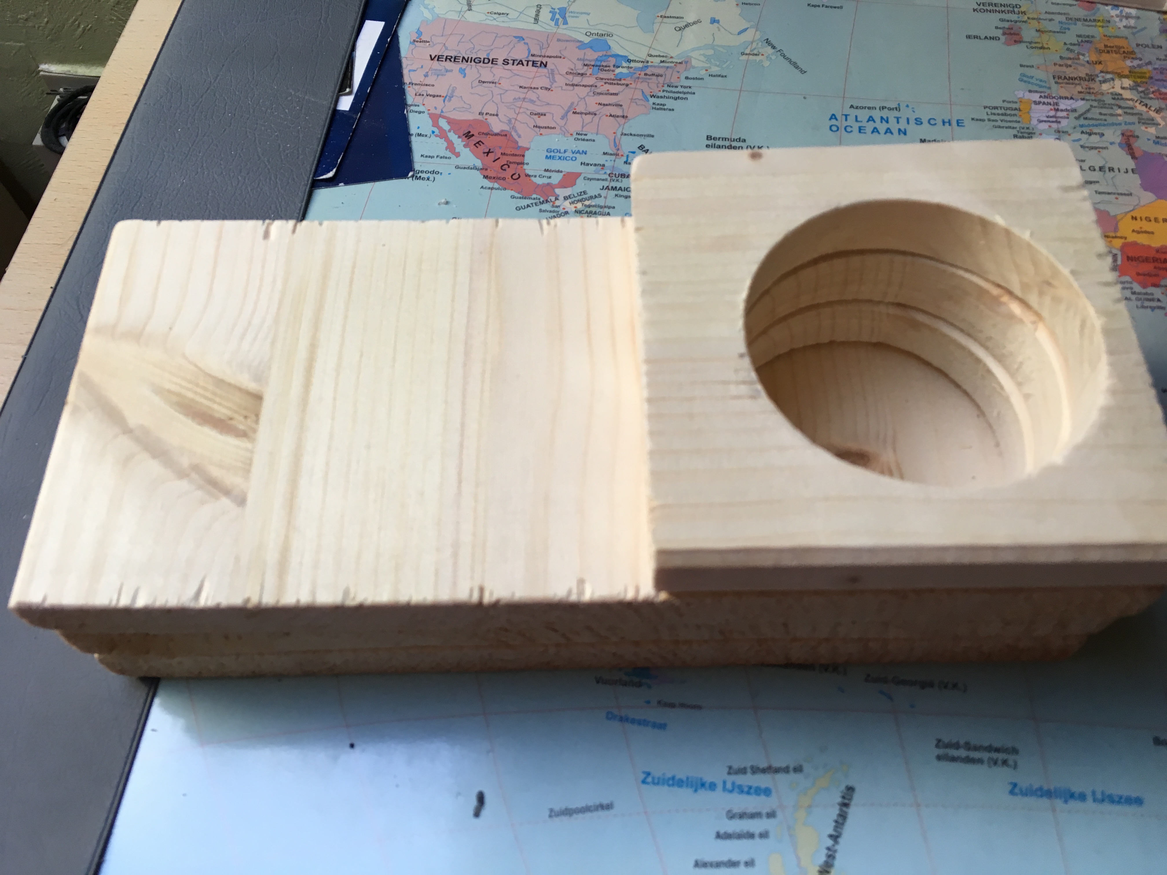
You're going to have four layers of wood in total which you can glue together with wood glue at the end of all the sawing. The top layer has a length and width of 9,5 cm.
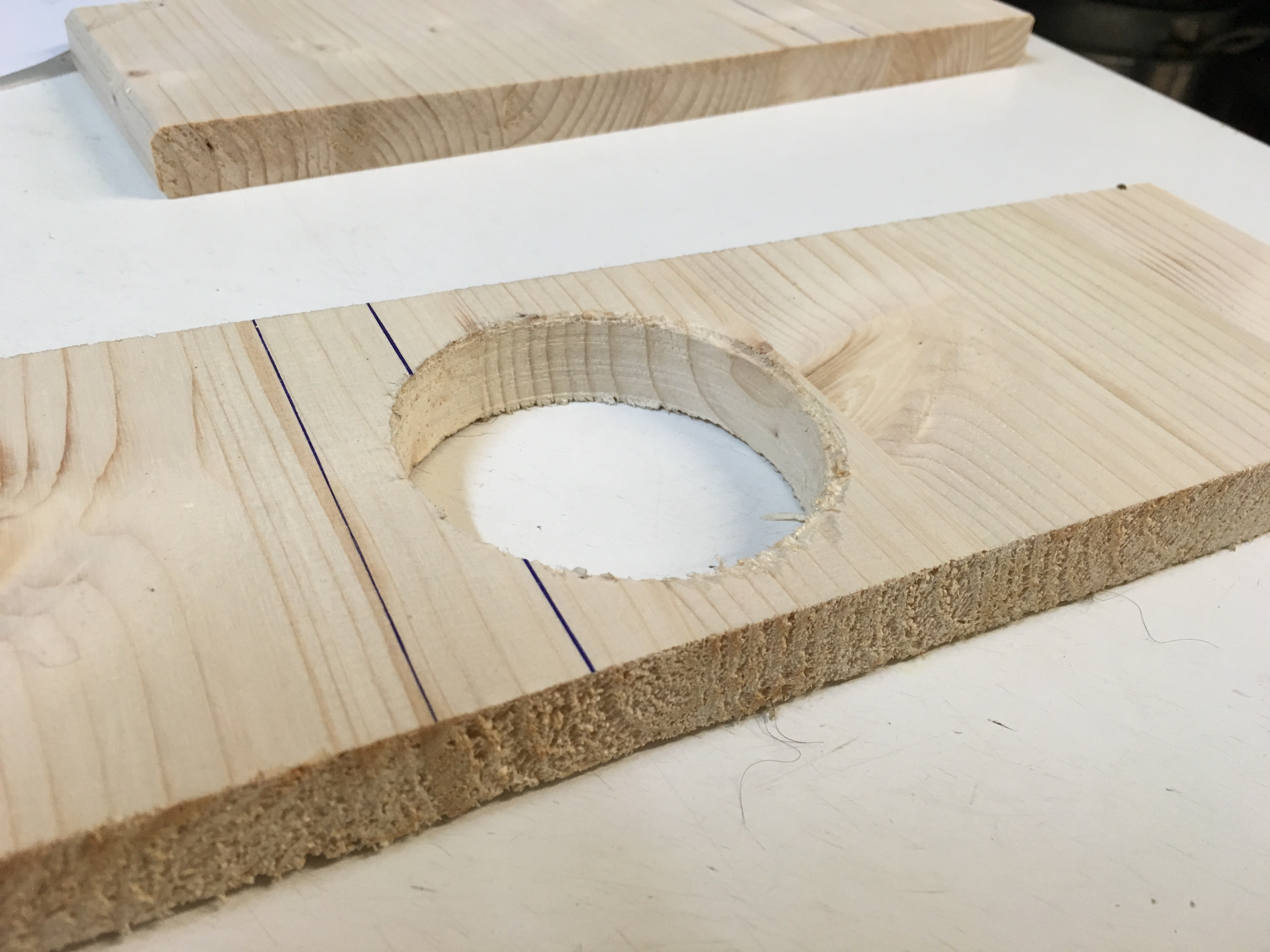
Firstly, saw the first piece of wood, this is the bottom of the cupholder. No hole should be sawn in this piece of wood. Secondly, use the hole saw with the drill to saw the holes out of the wood. Make sure the holes are identical and on the same spot on the wood! If you have your holes sawn out, saw the pieces of wood where you marked them. So now, you'll have your four layers of wood.
These four layers should be glued together with glue wood as you can see on the picture. Make sure everything is nicely and correctly placed because you're going to be glueing this permanently. (Unless you're like super strong and can tear them apart). Use a clamp to jam the pieces of wood together after you've glued them. After you've applied the glue, you have to let the glue sink in the wood for about 30 to 60 minutes.
And now you're done!
PCB on the Wooden Housing
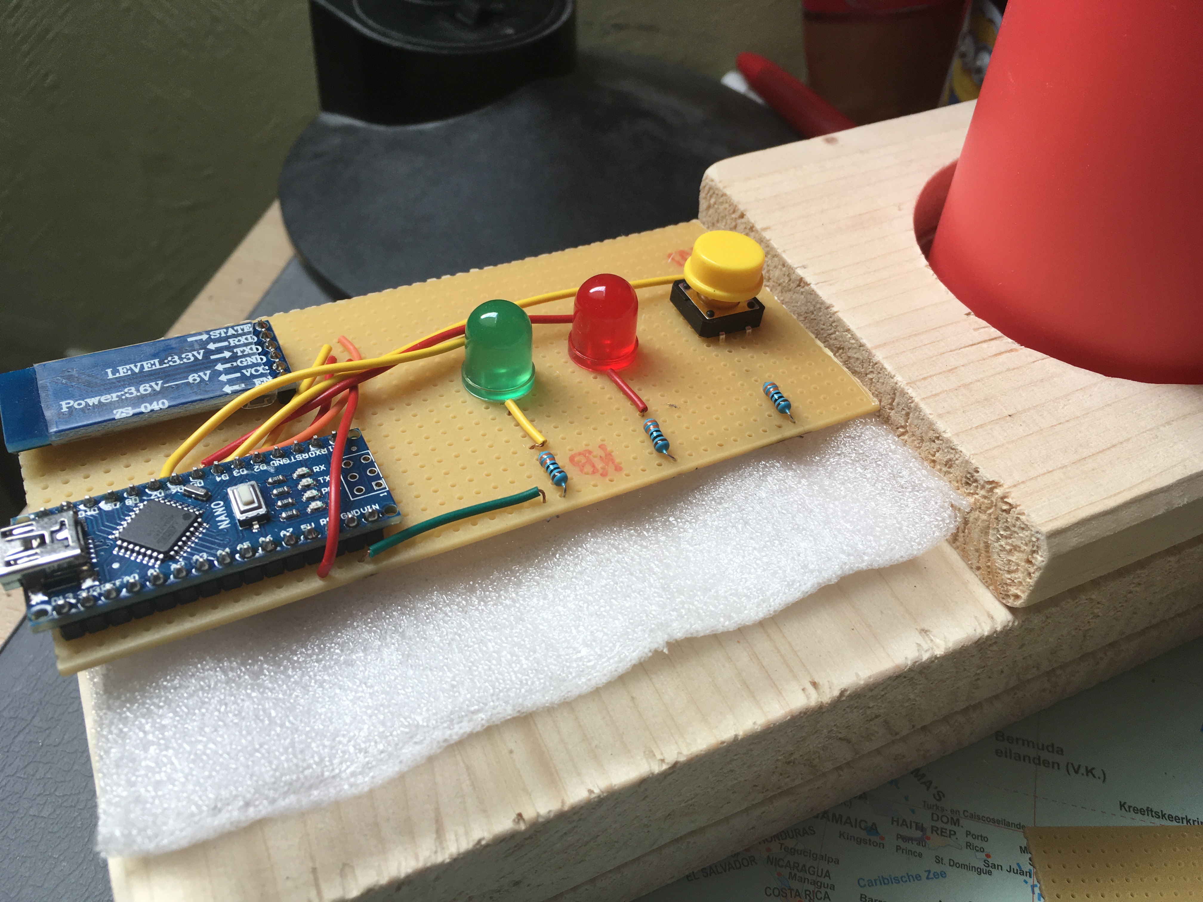
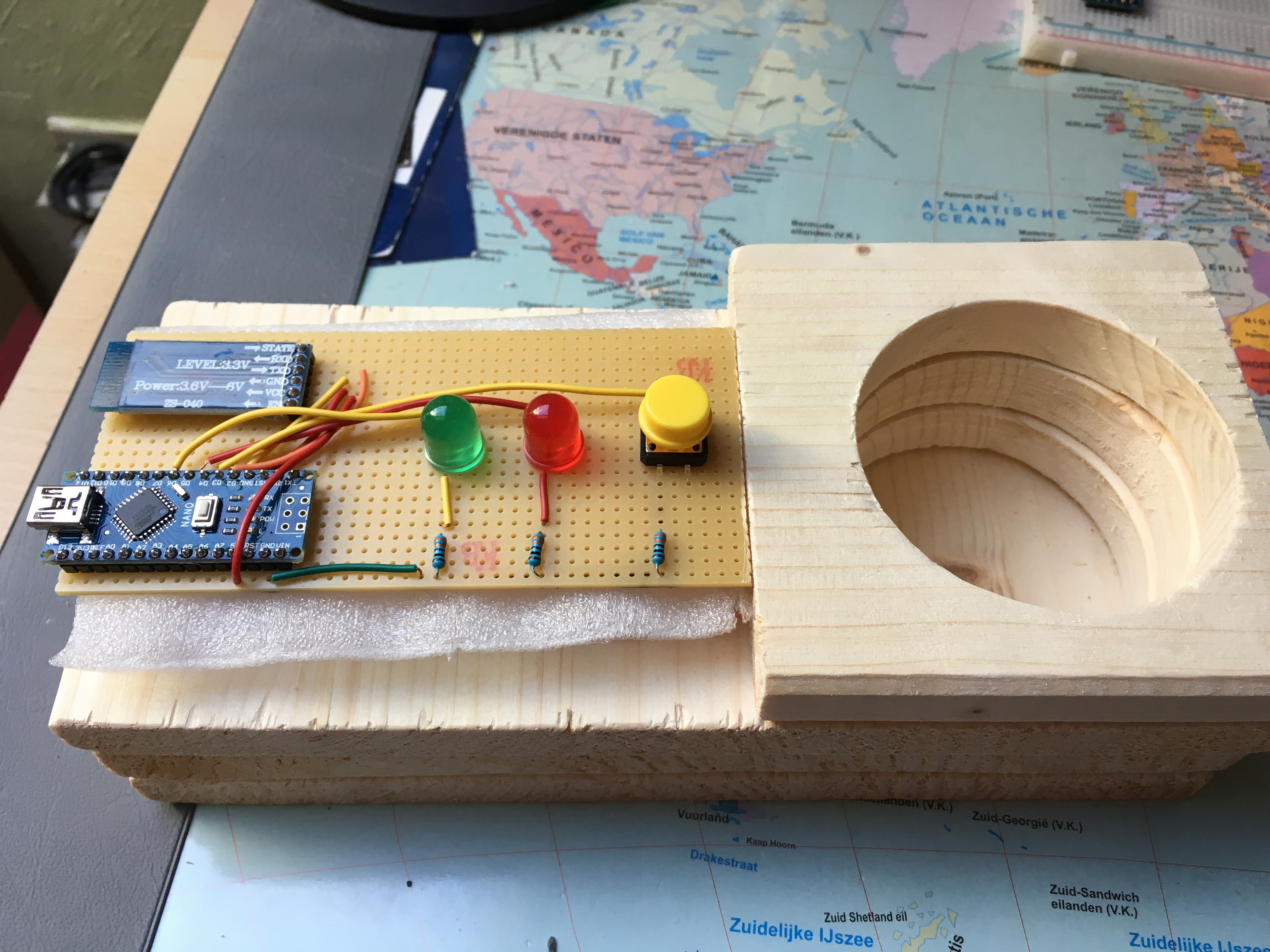
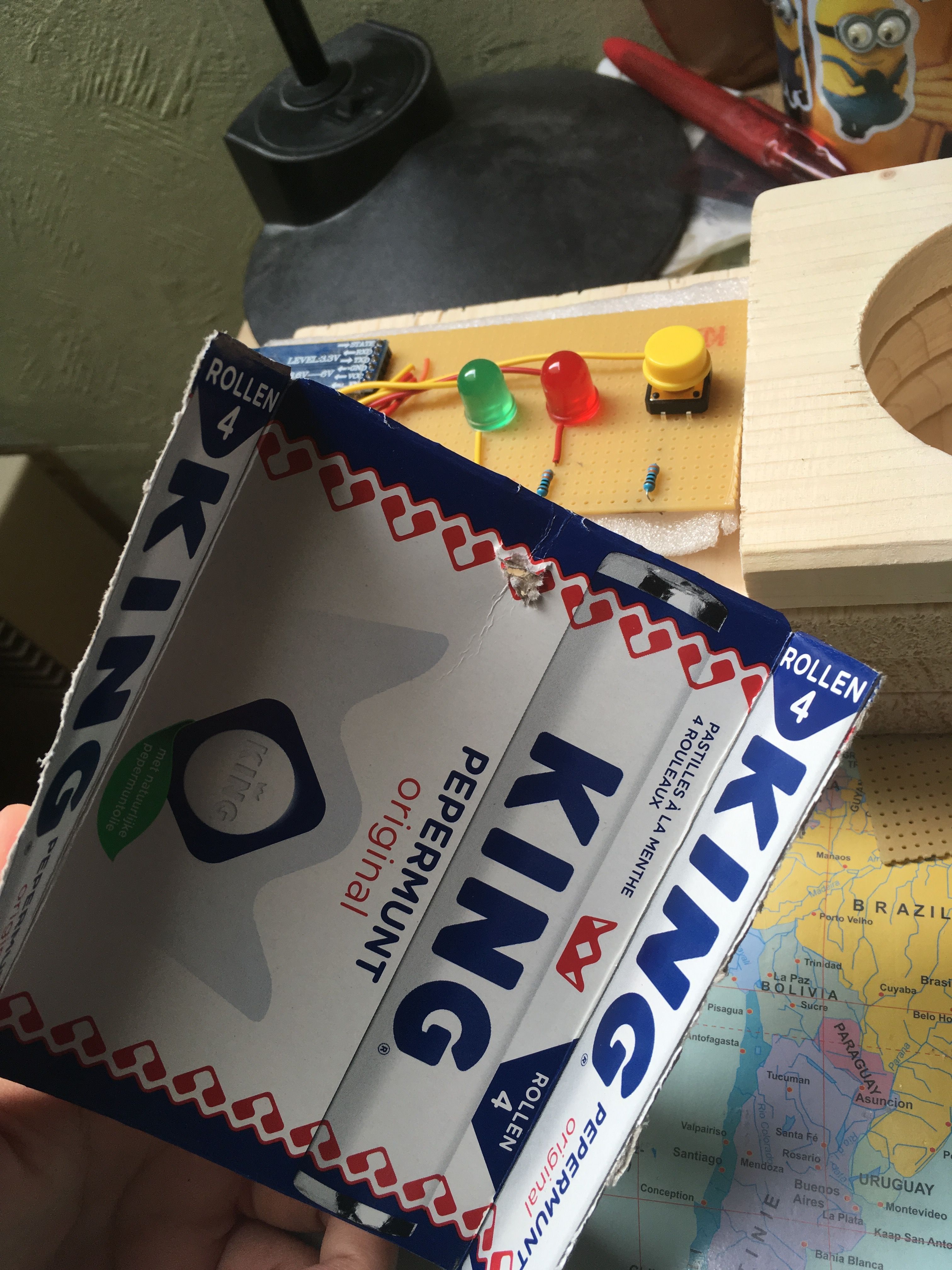
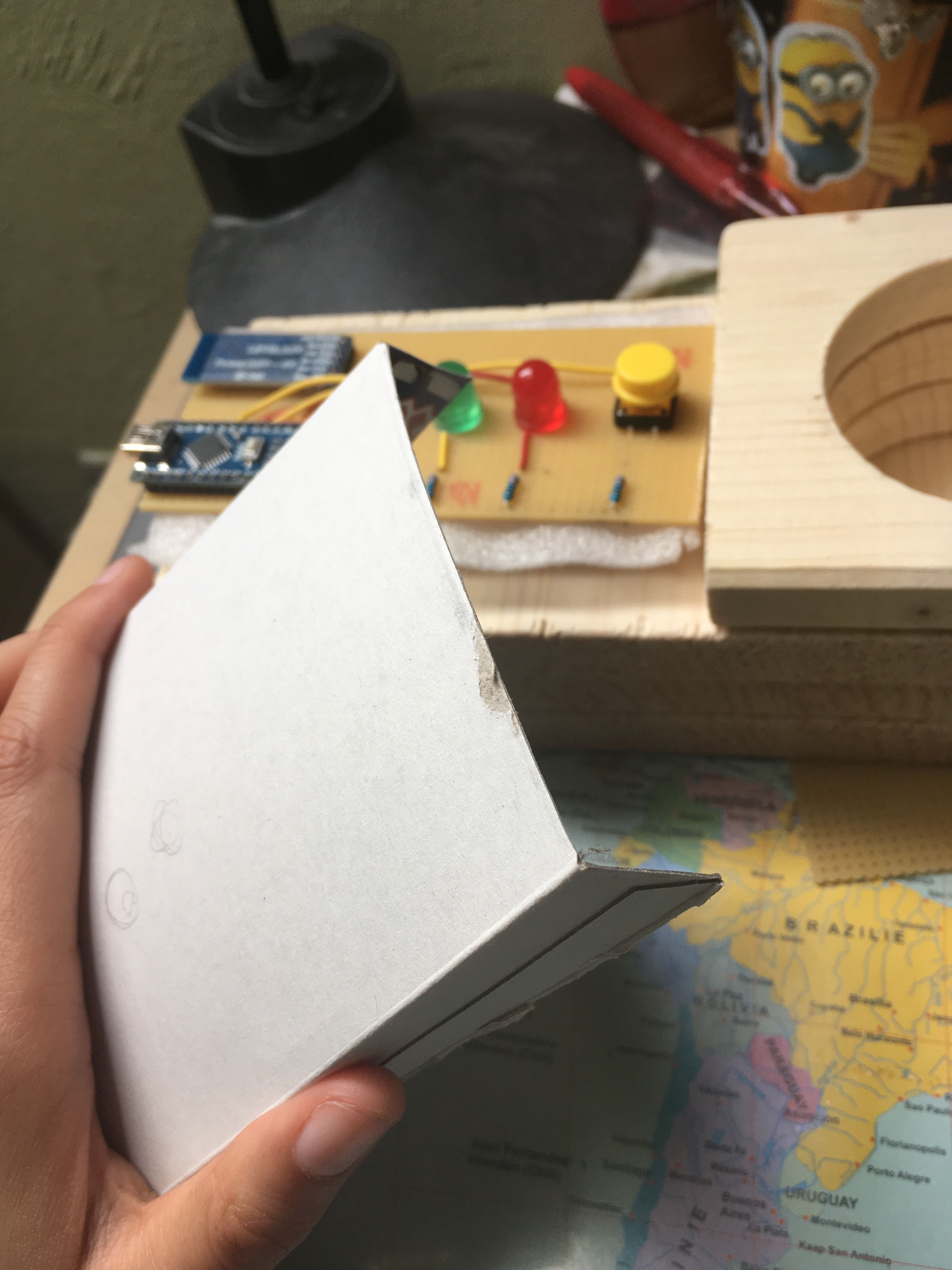
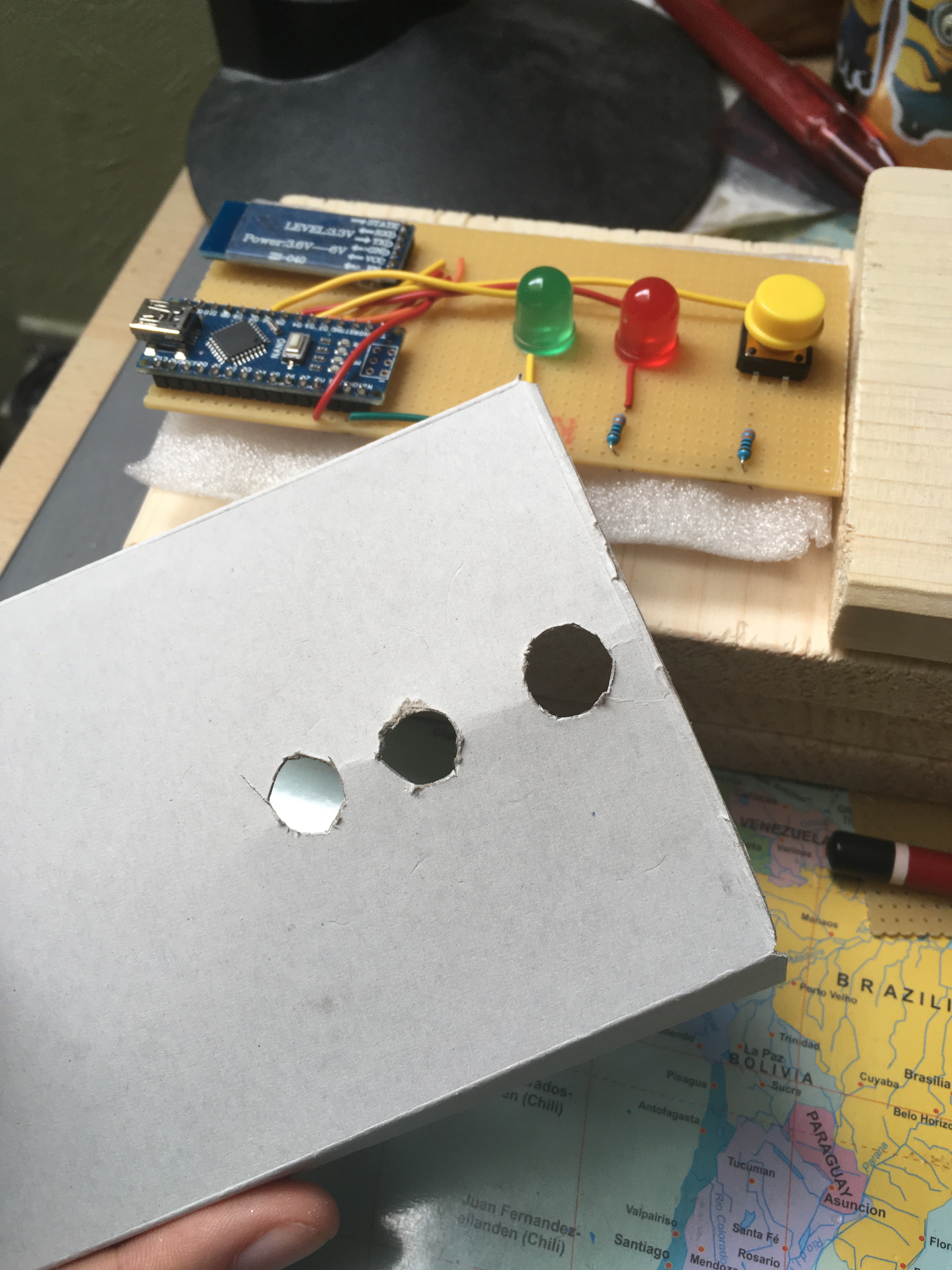
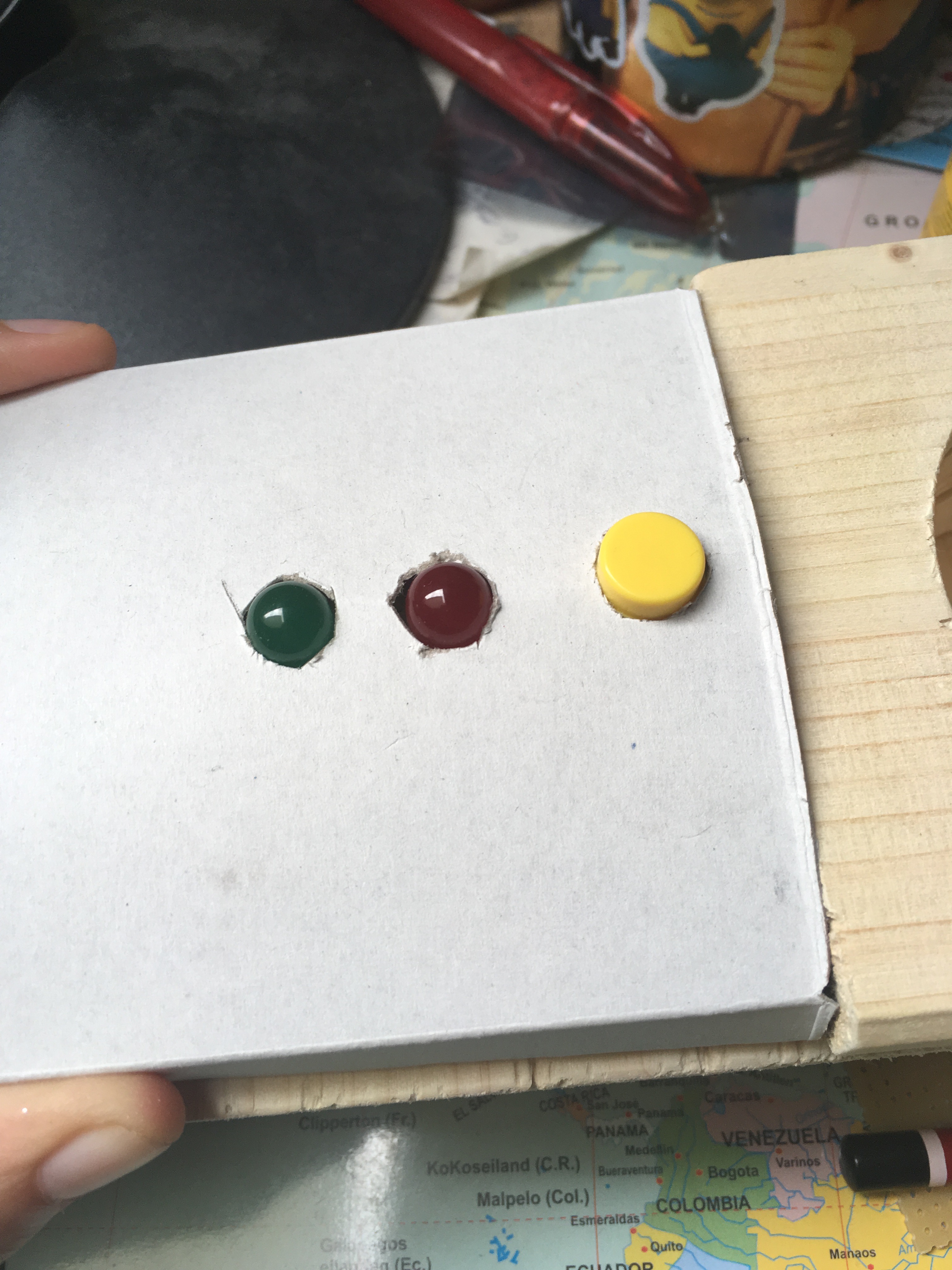
I purposely left a piece out of the top layer of wood so that I could place the PCB there. I used a white spongey-like material I once received with a package. You can use something else, I think bubble wrap can be used as well. I just wanted to make sure the PCB was stuck into something so the soldering work won't be damaged.
I didn't want the PCB to be so exposed and it doesn't look finished when there's nothing to cover the PCB. So I used a thin carton from a KING mints package. You can use cereal boxes or other thin cartons.
Luckily for me the KING mints package had the perfect width to put over the PCB, I just needed to adjust the length a little bit.
If you have your carton, make holes in it so the button and the two LEDs appear through the carton. You can make the holes using a utility knife.
Decoration
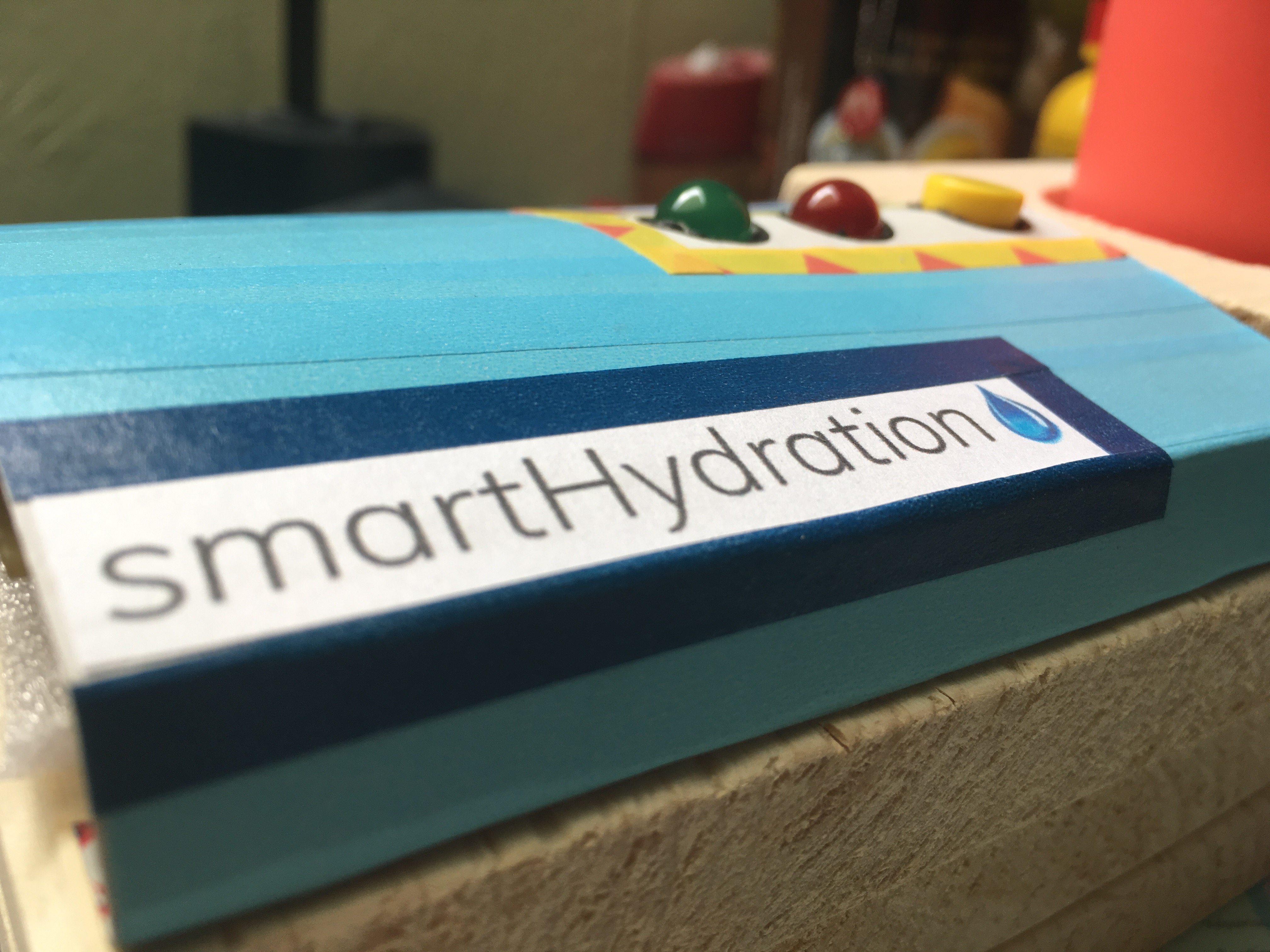
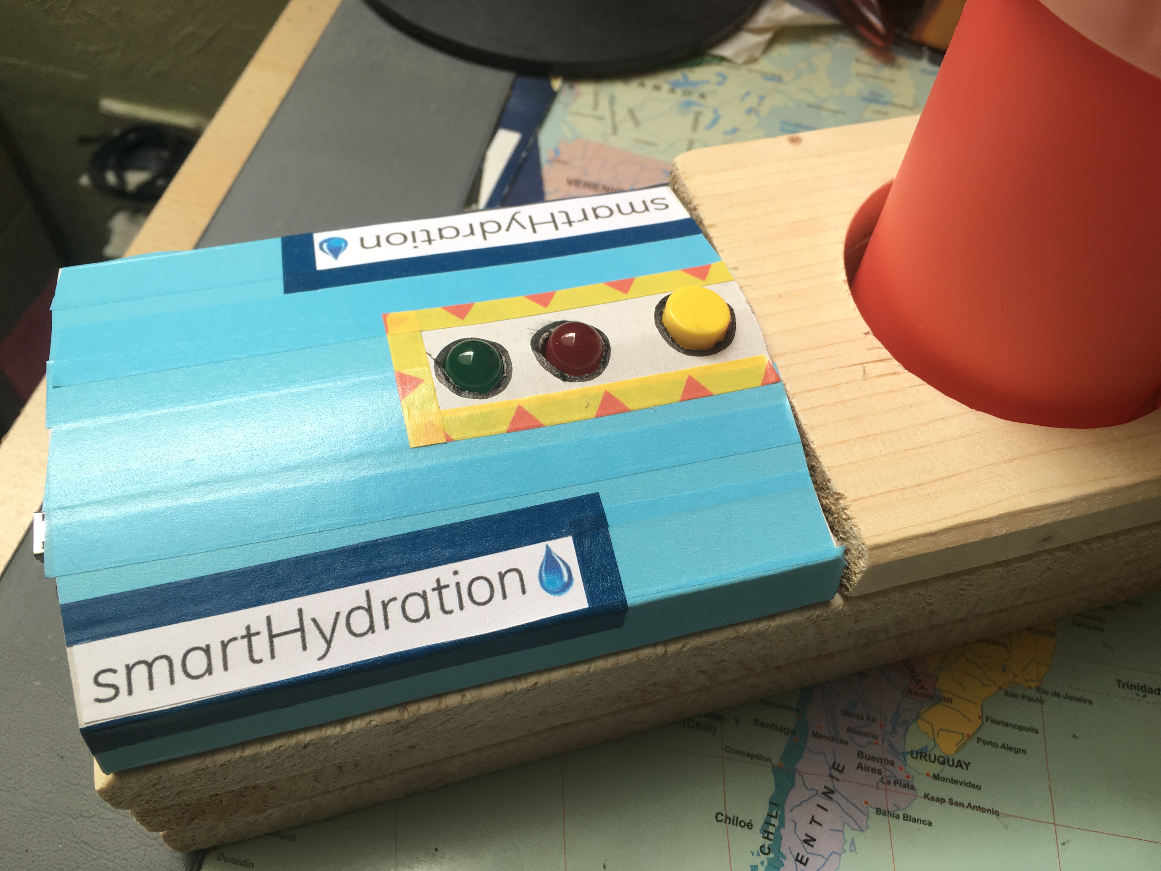
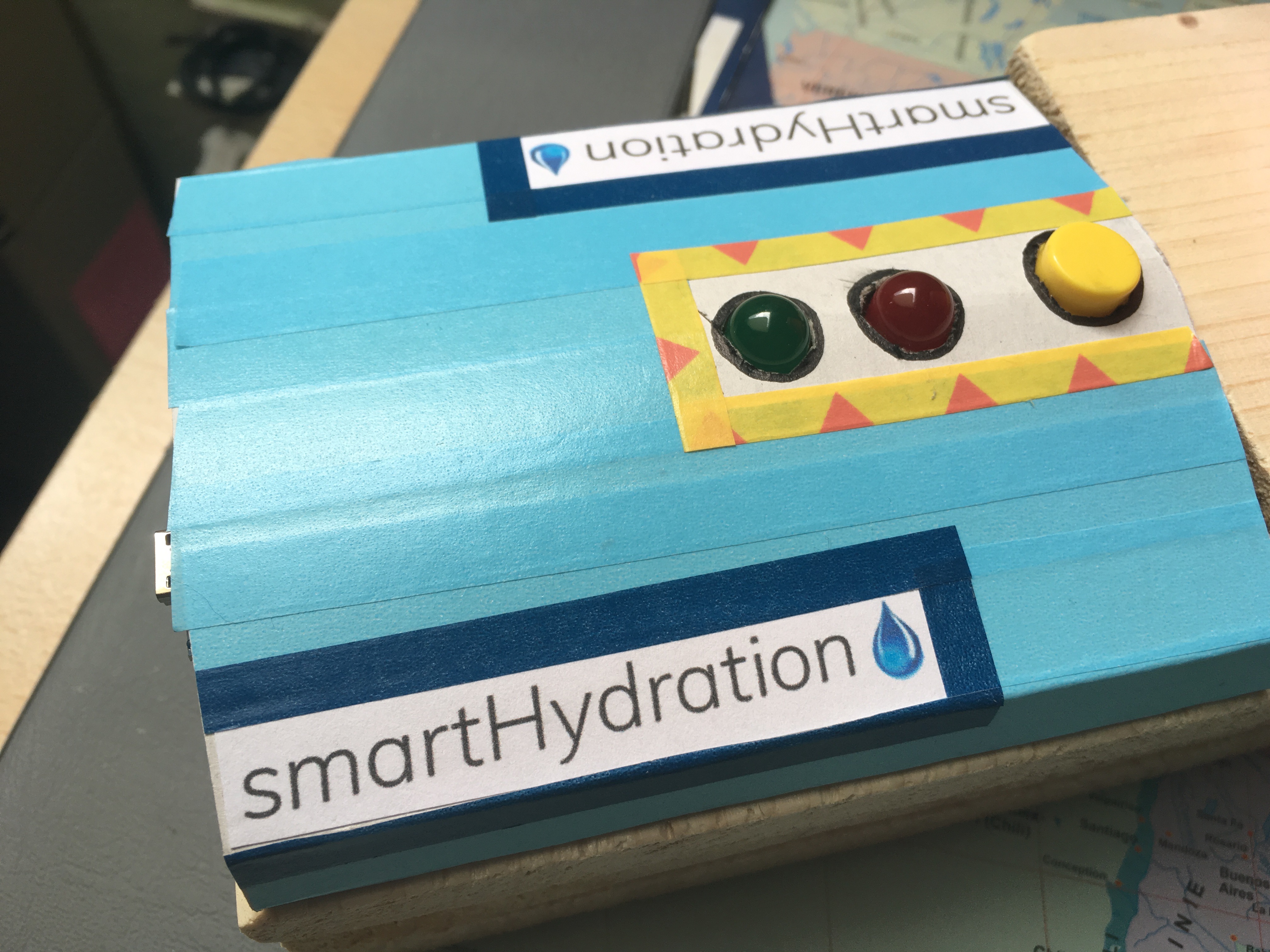
Now it's time for decoration!
This step is optional, if you like it the way it is, you can leave it like that.
I decorated my PCB cover with washi tape and I printed the logo of the name of my school project. I also encircled the holes with a thin black marker so that the holes look a little bit nicer and more finished.
Decorate it however you want it! It's time to be creative!
Final Product
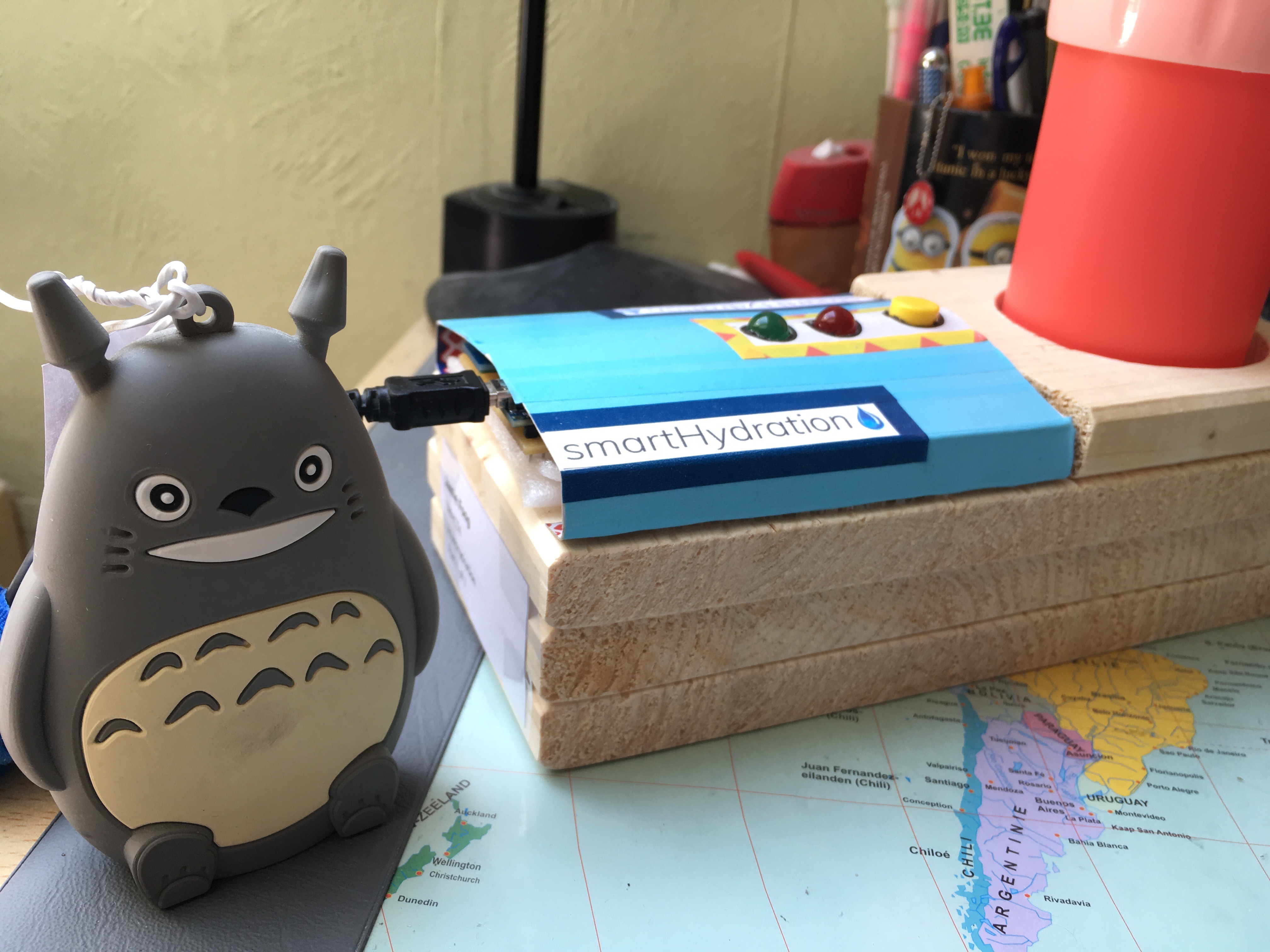
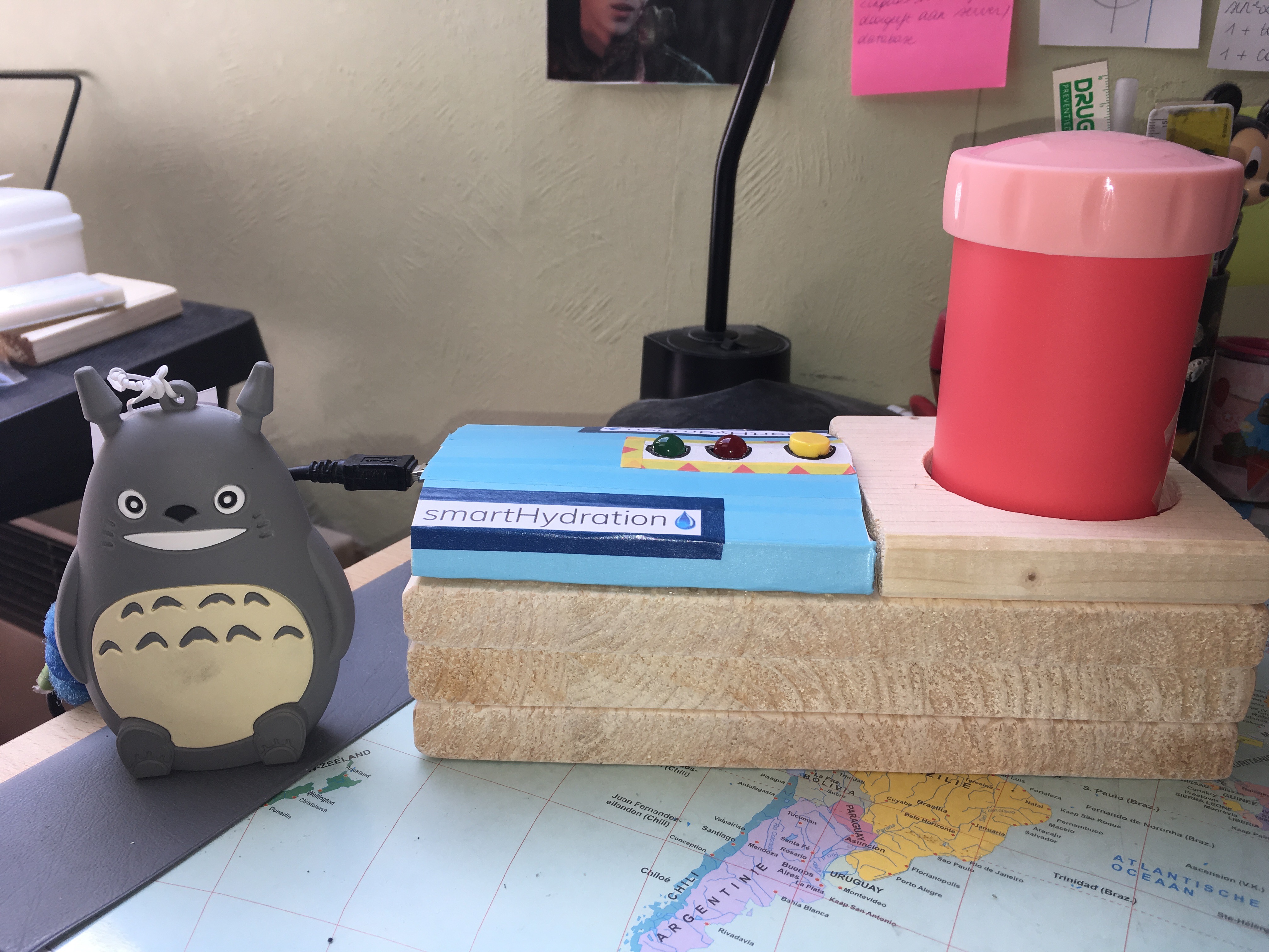
So here it is! The final product!
I used a powerbank (Totoro) to power the Arduino Nano so you can place it wherever you want in the room. If you prefer to use a socket, that's possible!
Hope this helped you!
Instructable PDF available in the attachments.