Smart Doorbell
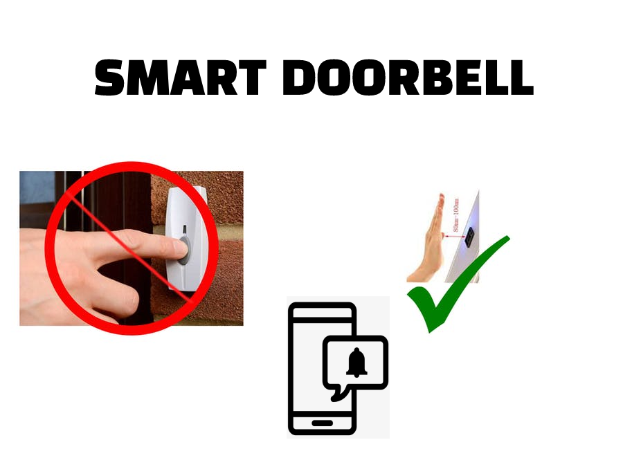
All thing are getting smart. What about your doorbell. Is that smart?. Smart doorbell systems are available in market. The true fact is it's really costly. Of course you can build your own doorbell by yourself. Only need some basic electronic and electrical knowledge. Not too much....This is not a rocket science.
Please be careful when play with high voltage. safety First!!!!!
Supplies
1. NodeMCU(ESP8266)
2. HC-SR04 Ultrasonic Distance Sensor
3 Doorbell
4 Smartphone
5 Soldering Iron and other tools
6.5V DC Power Supply/ Adaptor
7. 5V Relay Module
Hardware Setting Up
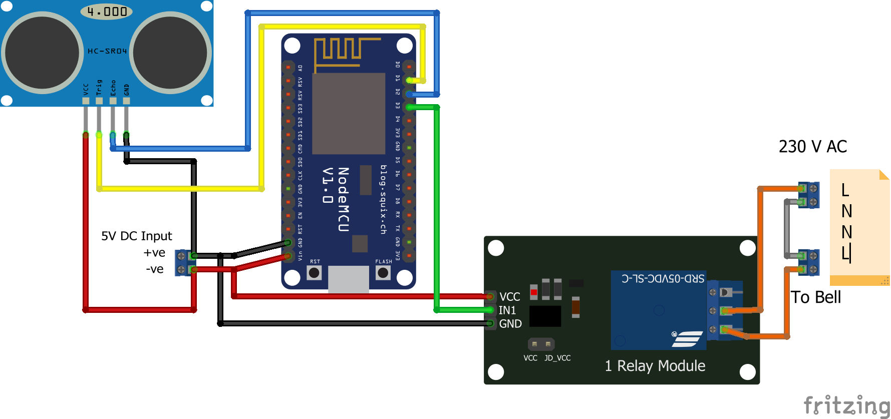
First I'm planning to do the hardware part. Connect the HC-SR04 Ultrasonic Distance sensor to the NodeMCU. Connect Vcc of the HC-SR04 to the positive of the 5V adaptor. Then connect GND pin of the HC-SR04 to the Ground of the adaptor. Next connect the Echo pin of the Ultrasonic sensor to the D2 pin of the NodeMCU. And connect Trig pin of ultrasonic sensor to the D1 pin of the NodeMCU. We made all connections from HC-SR 04 to the NodeMCU.
Next connect positive of the 5V adaptor to the Vin pin of the NodeMCU and GND pin located near to the Vin pin to the negative of the adaptor.
The last part is relay module. Connect the Vcc to the positive of adaptor and GND to the negative of the adaptor. At last connect IN pin of the relay module to the D3 pin of the NodeMCU. The hardware setup is completed.
Setting Up

Before we starting be aware of the components we are going to use.
1. NodeMCU
NodeMCU is a low-cost open source IoT platform. It initially included firmware which runs on the ESP8266 Wi-Fi SoC from Espressif Systems, and hardware which was based on the ESP-12 module. The firmware uses the Lua scripting language. The prototyping hardware typically used is a circuit board functioning as a dual in-line package (DIP) which integrates a USB controller with a smaller surface-mounted board containing the MCU and antenna. The choice of the DIP format allows for easy prototyping on breadboards.
Arduino.cc began developing new MCU boards based on non-AVR processors like the ARM/SAM MCU and used in the Arduino Due, they needed to modify the Arduino IDE so that it would be relatively easy to change the IDE to support alternate toolchains to allow Arduino C/C++ to be compiled for these new processors. They did this with the introduction of the Board Manager and the SAM Core. A "core" is the collection of software components required by the Board Manager and the Arduino IDE to compile an Arduino C/C++ source file for the target MCU's machine language. Some ESP8266 enthusiasts developed an Arduino core for the ESP8266 WiFi SoC, popularly called the "ESP8266 Core for the Arduino IDE". This has become a leading software development platform for the various ESP8266-based modules and development boards, including NodeMCUs.
(Source wikipedia.org)
1.1 Peripherals and I/O
The ESP8266 NodeMCU has total 17 GPIO pins broken out to the pin headers on both sides of the development board. These pins can be assigned to all sorts of peripheral duties, including: ADC channel – A 10-bit ADC channel.
The operating voltage of NodeMCU is 3.3v DC. There is a USB connector on NodeMCU development kit. We can power up NodeMCU via this connector with 5V DC. And There is also a Vin pin on NodeMCU development kit. We can give 4.5 to 10 V Dc to this pin. This pin is connected to a voltage regulator of NodeMCU development kit and it'll reduce the voltage to 3.3V.
2. HC-SR 04 Ultrasonic Distance Sensor
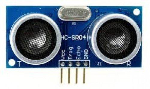
HC-SR 04 Ultrasonic distance Sensor is a type of distance sensor which works based on ultrasonic sound. Mostly this is used in hobby circuits and other prototyping purposes. HC-SR 04 is a 4 pin module, whose pin names are Vcc, Trigger, Echo and Ground respectively. This sensor is working based on ultrasonic sound. This sensor have two eye like structures. One is Transmitter and other is Receiver. The sensor working formula is given below
Distance = Speed x Time
The transmitter part of the HC-SR 04 transmits a wave in ultrasonic frequency, this wave travels through air and when an object is on the path of this wave, the wave will collide with that object and reflect back.The receiver part of the HC-SR 04 will receive this reflected wave.
Then calculate the distance using the above formula. We know the speed of ultrasonic sound in air is 330m/s. Now we want the time. The circuits in the HC - SR04 will calculate the total time travelled by the Ultrasonic wave. We only need the half of this total time. That means the time for travel an Ultrasonic Wave from Sensor to the object. Or Object to the sensor. Both are same. This calculation and other will do the microcontroller. In our case its NodeMCU.
3. Blynk
Blynk is a platform that allows you to quickly build interfaces for controlling and monitoring your hardware projects from your iOS and Android device. After downloading the Blynk app, you can create a project dashboard and arrange buttons, sliders, graphs, and other widgets onto the screen. In short Blynk is a server and it have an Application software to interact with connected devices(Clients). Here we only use the notification widget in the Blynk.
4. Relay Module
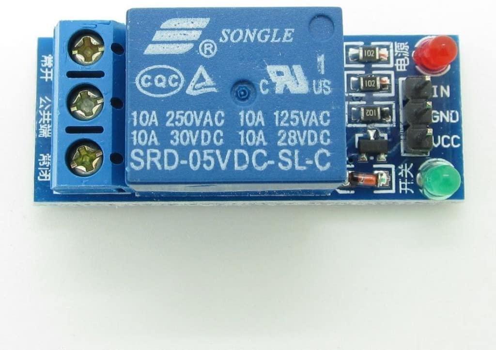
A relay is basically a switch which is operated by an electromagnet. The electromagnet requires a small voltage to get activated. Once it is activated, it will pull the contact to make the high voltage circuit.
Relay module means relay with driver circuit for relay. An MCU(here NodeMCU) is not enough to activate the relay coil. So we need a small supporting circuit known as driver circuit. This driver circuit is not complicated circuit. Its just a BJT and flyback diode. The whole circuit with relay is known as "Relay Module".
Here I'm using 1 channel relay module. Because we only have 1 device to operate (Door bell). One channel relay module have three male header pins and three screw terminals. Three headers are named as IN, GND and Vcc Respectively. 'IN' pin for signal input. When we give HIGH (Logically 1) , the relay is activated. and the pins GND and Vcc are power supply pins for the relay module. You must connect the GND pin of the relay module to the MCU's GND when you use additional power supply for relay module.
Install and Configure Blynk
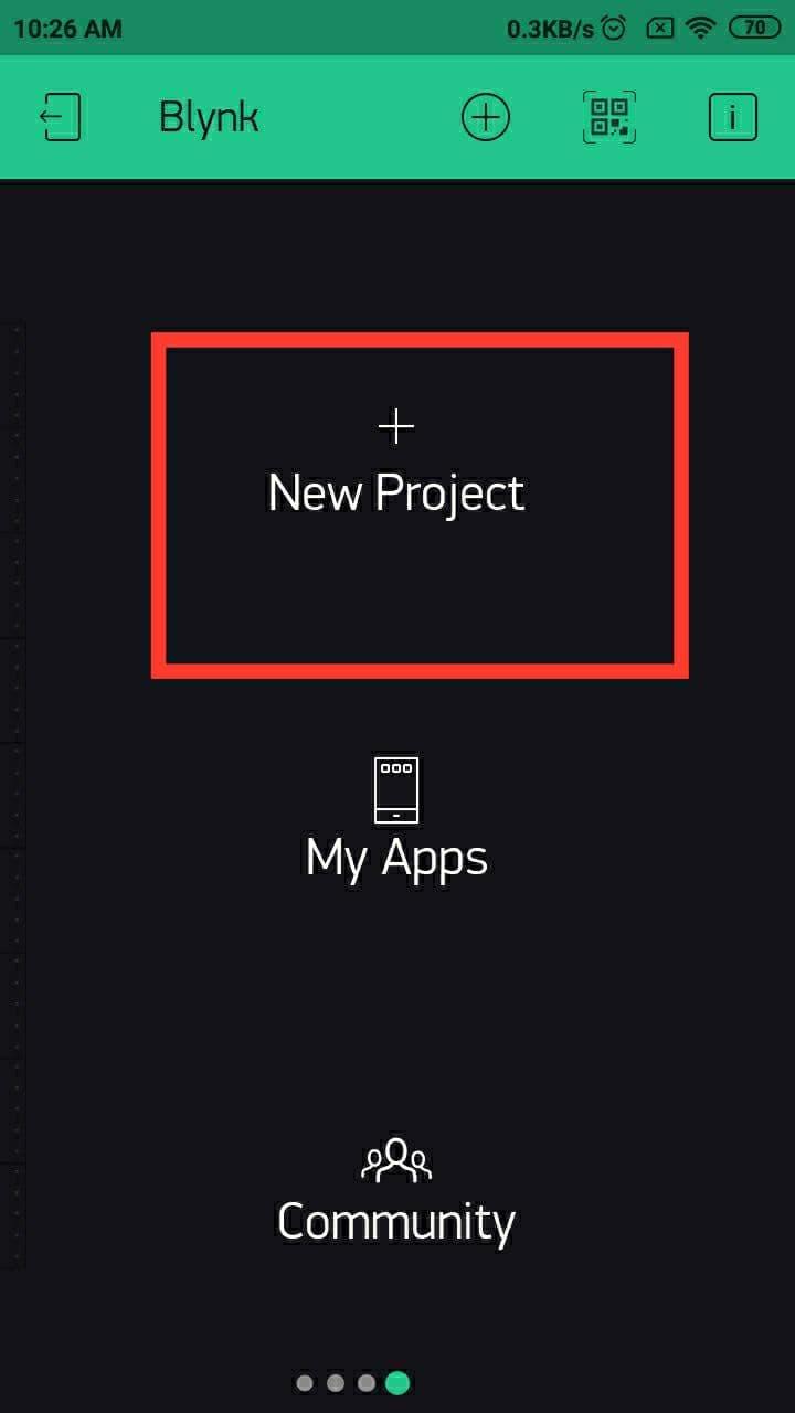
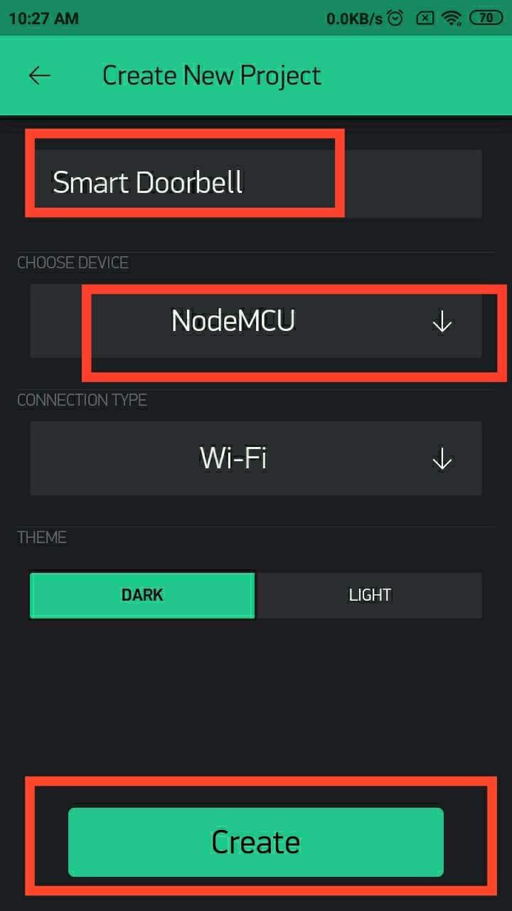
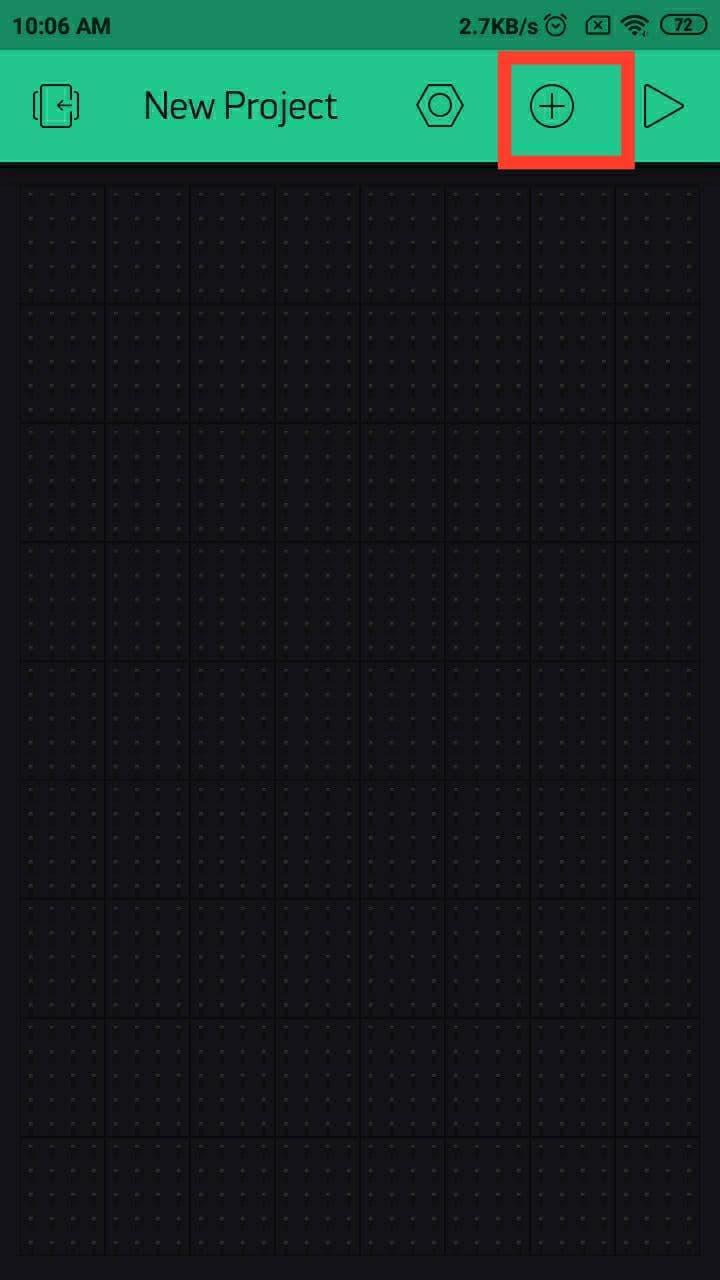
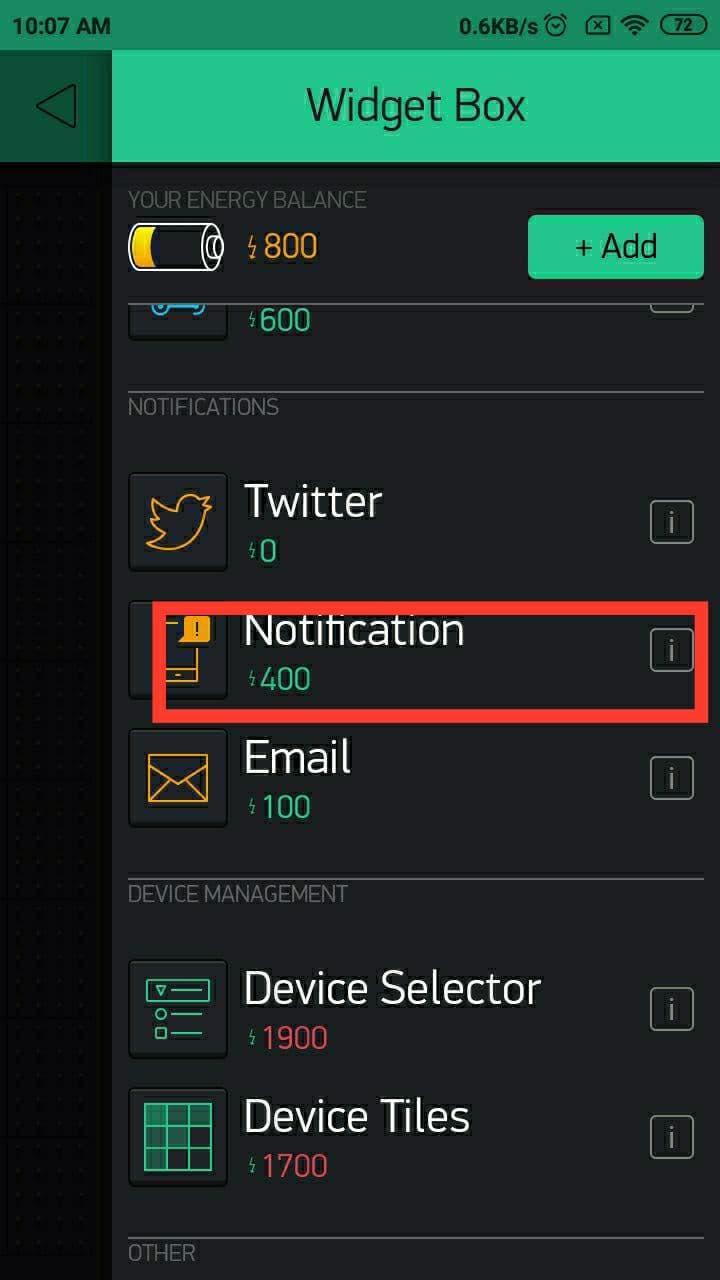
Next we need to install Blynk app to get notification on our smartphone when a visitor rang the doorbell. Click here and go to the link and install Blynk app. Here I only give the Android application link. Alternatively you can download the Blynk app for iPhone.
After installation of App open it and create an account. Next login and you can see a page like the first image. Click the "New Project". Then give a project name in top bar. Next choose the device. In our case its NodeMCU. So scroll down and choose NodeMCU and click "ok". Next click "Create" button on the bottom. After that you can see a dial out says "Auth token was sent to :<Your email id>". Click the "Ok" button. We need the Auth token in future.
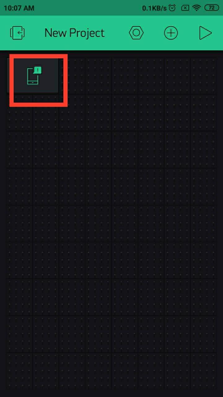
You are redirected to dashboard. Next click the "+" icon with circle located on top. Next scroll down the page and click "Notification"
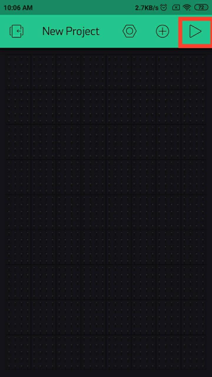
Again you are redirected you the dashboard. Now you can see a notification icon on dashboard. Next click the Run button located on top right corner.
Installation and configuration of Blynk is completed now.
Software Section
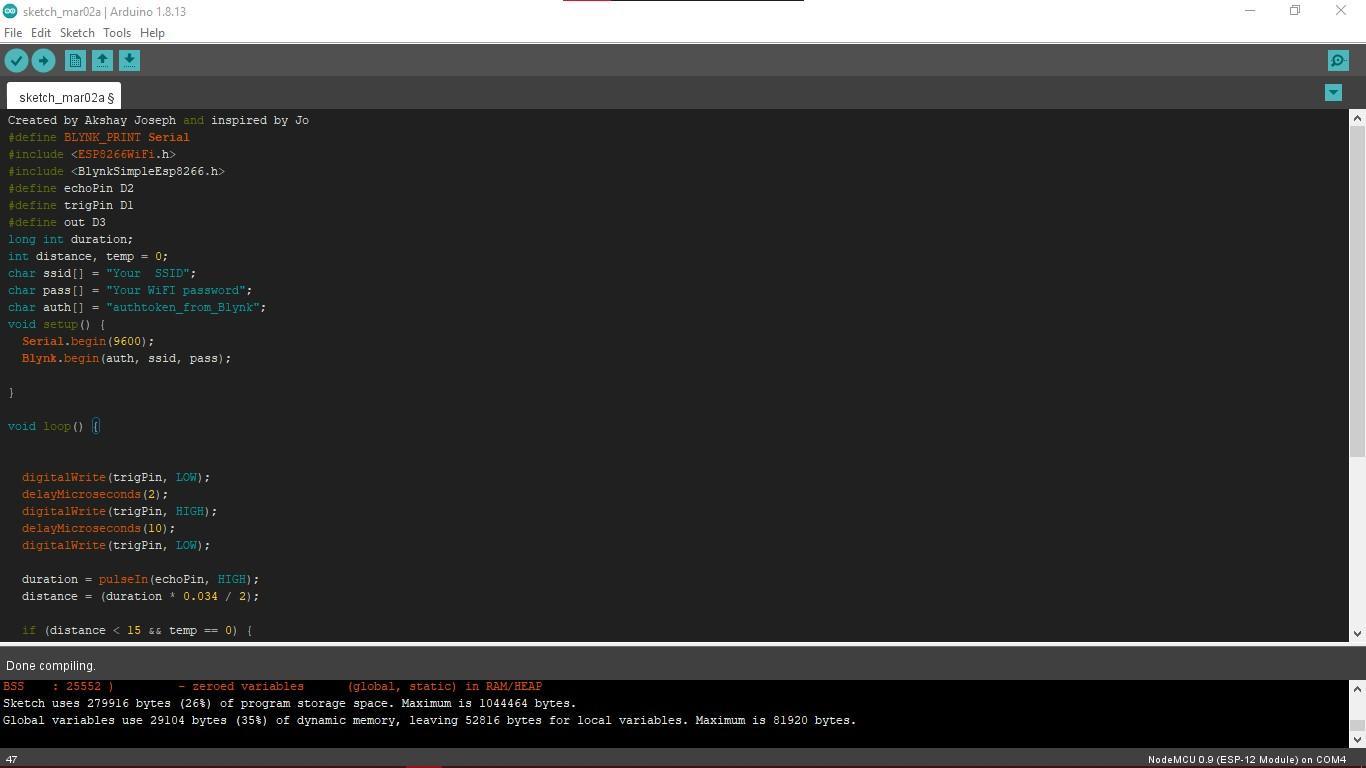
Here we are going to use Arduino IDE for program NodeMCU. if you didn't use Arduino Ide for NodeMCU before, please refer my hackster tutorial. Follow the four steps under the heading "Setting up the Arduino IDE for NodeMCU". Click here to read the instructions.
After setting up Arduino IDE for NodeMCU go to the Github repo "Smart_Doorbell" and copy the code then paste it to the Arduino IDE.
We need to edit some parts of this code.
You can see "Your SSID" on the 10th line of the code. Replace it with your WIFI router's SSID/Network name
And the next line you can see "Your WiFI password" Replace that text with your WIFI's password. Then in next line you need to change the "authtoken_from_Blynk" with your auth that given the time of configuration of Blynk(copy it from your email inbox).
Then upload the code to NodeMCU.
Once you successfully uploaded the code disconnect the USB cable from NodeMCU and power on the adaptor and supply to the bell.