Smart Bin - MECHX & DM 2024/25
by binsmart1 in Workshop > Laser Cutting
2358 Views, 8 Favorites, 0 Comments
Smart Bin - MECHX & DM 2024/25


Project Abstract
Have you ever had the trash can in your restaurant or cafe fill up in the blink of an eye, and you're constantly emptying it in the middle of service? No more! We've designed a revolutionary prototype: a trash can that automatically compresses waste, optimizing space and reducing emptying frequency. Imagine fewer interruptions, more efficiency, and a cleaner work environment, all with just one special trash can. Ready to transform the way you manage waste in your business?
Following the Mechatronics 1 course given at VUB/ULB Electromechanical Engineering Master Program, us, a group of 6 students, had the opportunity to design and build a prototype that solves this terrible waste management problem. The construction was made in Fablab VUB, were several 3D printers and wood laser cutters were made available to us.
The Smart Trash Bin is an innovative and user-friendly waste management solution designed for indoor spaces like fast food restaurants and small businesses. This product automates trash compaction and monitoring to maximize efficiency and reduce manual intervention. Equipped with an HC-SR04 ultrasonic sensor, a linear actuator that powers a scissor lift mechanism for trash compaction, and a magnetic reed switch for security, the bin offers enhanced functionality with safety as a priority.
Table of contents
- Project motivation
- Project working requirements
- State of the art and patent analysis
- Conceptual design
- Embodiment design
- Design of subsystems
- Mechanical Systems
- Circuitry & Sensors
- Software
- Integration guide
- Demo project show
- Critical review of the project
- Sustainability
- Bill Of Materials
- Team presentation
- Project repository
Project Motivation


Personal Experience
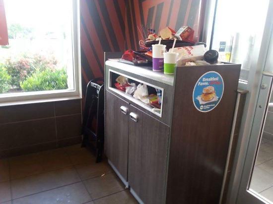
Imagine finishing a meal at a fast food restaurant and struggling to dispose of your trash into an already full bin. You might find yourself placing waste on top or leaving it on the table. Worse yet, you might wander around in search of an empty bin. These situations are inconvenient for customers and might harm the fast-food chain reputation for cleanliness and efficiency.
Fast food chains, which experience high foot traffic and generate significant amount of waste are particularly concerned. Overflowing bins create unclean environments, workers must frequently check and empty bins, diverting time from other tasks, making waste management a persistent challenge.
The idea of this project also comes from the personal experience of one of the Team Members. While still in the brainstorming phase, he went on a weekend trip to Amsterdam. There he had one of the best bitterballen he had ever tried, in a restaurant called Heertje Friet, right on the city center. However he found that, while this being a predominantly take-away spot, the only trash bin available was a public one located beside the shop, which can be seen in the picture above. It was overflowing. Lots of food containers, with the printed logo of the shop, thrown on the floor. Signals in the shop window explicitly asking to please throw the trash in the bin so it does not get into the canal. In short: a bad image for the restaurant and for the neighborhood.
The Smart Bin addresses these issues by providing an efficient waste management solution. It compacts trash, ensuring that the bin can hold more waste, reducing the frequency of emptying, and maintaining a clean, user-friendly environment for customers.
Goal of the project
How can we design a waste management system that:
- Prevent overflowing bins in fast food restaurants, ensuring cleanliness and efficiency?
- Optimize waste capacity to reduce the frequency of trash collection?
- Enhance customer satisfaction while simultaneously improving operational efficiency for fast food chains?
Our Smart Bin addresses these issues by providing an efficient waste management solution. It compacts trash, ensuring that the bin can hold more waste, reducing the frequency of emptying, and maintaining a clean environment for customers. LED indicators help show when the bin is full, which is more practical for both customers and workers.
Persona identification
User Persona are fast food customers. They need a clean and intuitive bin to avoid dirty or overflowing bins. Customers prefer to dispose trash quickly and efficiently. The Smart Bin’s LED Indicator allow them to identify an available bin from a distance.
Buyers Persona are fast food chains. They want to improve cleanliness and ensure positive customer experience, optimize waste storage, and workers to focus on customer service rather than emptying bin all day long.
Quantification of the need
Quantifying the need for efficient waste management in fast food restaurants involves both survey data and industry statistics:
- 75% of customers will not visit a restaurant with negative review about its cleanliness [1]
- 44% of customers prioritize cleanliness when choosing a restaurant [2]
- 46.5% of employees rated sanitation efforts of ultra-high importance [3]
- Compacting system reduce waste volume by 50% to 80% allowing a single Smart Bin to hold the equivalent of up to 3 traditional bin [4]
By addressing these needs, the Smart Bin delivers overall improvements.
- https://www.jolt.com/blog/restaurant-cleanliness-statistics/?srsltid=AfmBOorvIpZJUdBqpByFPJVJVXA6Rp40OdpWO7TFNE6Ld_NXQoNo8CRW
- https://www.zenger.news/2024/01/25/44-of-americans-prioritize-cleanliness-when-choosing-a-restaurant-survey-shows/
- https://www.ecubelabs.com/overflowing-garbage-bins-5-impacts-on-health-and-environment-and-how-to-prevent/
- https://www.trashrite.com/blogs/news/transforming-waste-management-with-the-garbage-compactor-revolutionizing-cleanliness-and-efficiency
Project Working Requirements

Smart Bin functionalities
- Waste compaction reduces the volume of trash, optimizing bin capacity and minimizing emptying frequency.
- LED indicators: display the bin’s status (ready to use, compacting, full).
- Door locking system with magnetic sensor: ensure the bin is securely closed during compaction for user safety.
- Full level detection uses LiDAR sensor to identify when the bin is full and trigger compaction.
Our Smart Bin does not sort waste and can’t be used outdoor but operates indoors in high-traffic fast food restaurants. It is used by the customers and requires user-friendly operation.
Objectives and constraints
Our main objectives are to:
- Maximize bin capacity through effective compaction.
- Ensure safety and ease of use.
- Provide clear visual indicators.
- Optimize durability and reliability for continuous use in fast food restaurant.
The general table of constraints and means of fulfillment can be seen in Table 2.1.
Requirements list
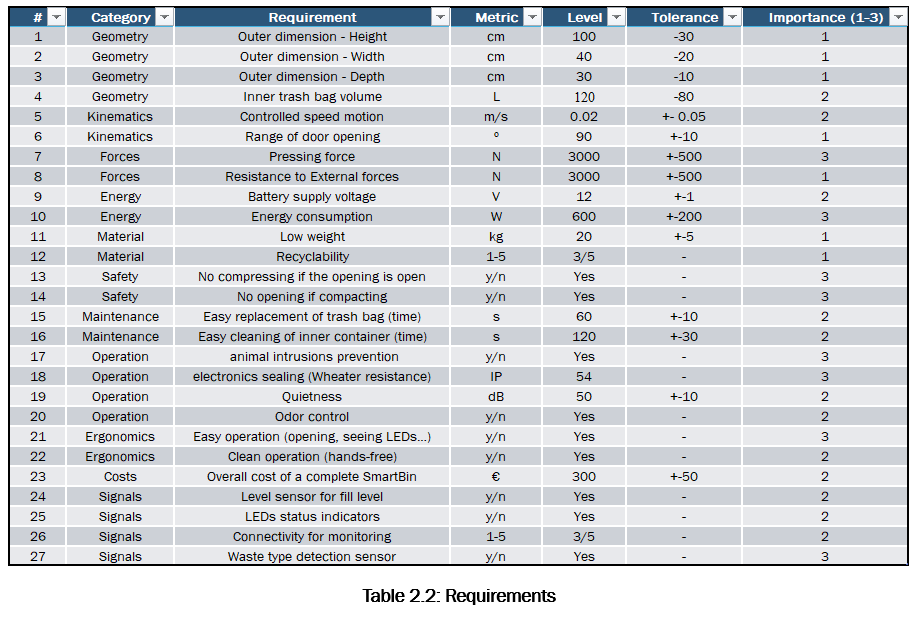
The Table 2.2 shows all the objectives and constraints that were followed in the development of the solution to answer the problematic. Priorities of the criteria are ranked from 1 to 3 and requirements are quantified as much as possible in terms of category, metric, level and tolerance.
Eco-Design analysis
A high attention will be paid on:
- The material selection, favorizing environmentally friendly material and reusability for future projects without compromising performance.
- Energy efficacy because reduced power consumption lowers the carbon footprint of the bin’s operation.
- Durability to ensure the bin is robust and minimize replacements.
- Disassembly, simplify disassembly for recycling at the end of the product’s life and change the critical part easily, in few steps.
- Life cycle: green manufacturing, low-energy operation and recycling or reusability will be prioritized.
Conclusion
This section gave a detailed overview of the Smart Bin’s functionality, constraints, and key design considerations to address the problem of inefficient waste management in fast food. The constraints such as robust compacting systems, ergonomic design, and water resistance ensure that our solution will meet the operational demands. The objectives and the constraints provide a comprehensive understanding of what our Smart Bin aims to achieve, the challenges it must overcome, and the measures required to bring our concept to life.
State of the Art and Patent Analysis


State of the art
To position our product within the waste management market, we conducted an analysis of both direct and indirect competitors. This assessment focused on identifying the strengths, weaknesses, and features of existing products to highlight our product’s unique value proposition.
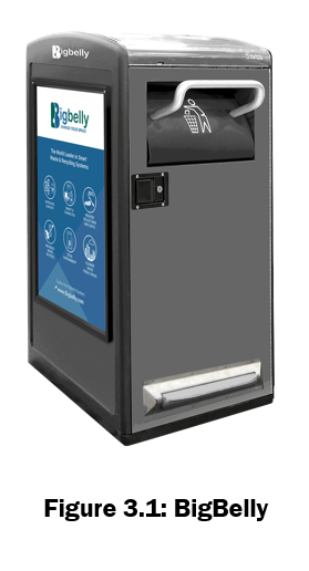
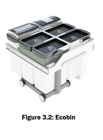
Our primary direct competitors are Bigbelly and EcoBin, both of which offer technology-integrated solutions for waste management. These competitors address problems similar to ours, such as the need for improved waste collection efficiency and sustainability.
Standard Trash Bins
• Strengths: bins are widely available, low-cost, and easy to use, making them a popular choice for households, offices, and public spaces.
• Weaknesses: Standard bins lack modern functionalities such as compaction or fill-level notifications. This results in inefficient waste collection processes, leading to overflowing bins and frequent trips for collection.
Bigbelly (Fifure 3.1)
• Strengths: Bigbelly is a solar-powered smart trash bin system that integrates automatic compaction and fill-level notifications. It is ideal for high-traffic public spaces like parks and streets, significantly reducing collection frequency and environmental impact.
• Weaknesses: The high initial cost makes it less accessible for smaller businesses, households, or low-traffic areas. Its focus is primarily on public spaces, limiting its applicability to other environments like offices or restaurants.
EcoBin (Figure 3.2)
• Strengths: EcoBin specializes in waste segregation, supporting recycling initiatives by separating materials like paper, PMC (plastic, metal, cartons), and organic waste. It also includes smart fill-level notifications, which optimize collection schedules. EcoBin is highly customizable for settings like campuses or offices
• Weaknesses: While EcoBin excels at waste separation, it lacks compaction technology, limiting its ability to handle large volumes of waste. Additionally, its cost is relatively high, which may deter small-scale users such as restaurants.
Patent Analysis
In this analysis, we compare our smart trash bin design with relevant patents to establish the freedom to operate (FTO). The patents reviewed include US2020139655 (A1), US2019375177 (A1), DK201700154 (A1), and US10596775 (B2). Our findings confirm that our design incorporates unique features and mechanisms, distinguishing it from the technologies described in these patents.
Major Patents Reviewed:
- US2020139655 (A1) (Figure 3.3) - Portable Compaction Apparatus for Compacting Trash and Other Materials
- Description: This patent describes a trash compaction system with a linear actuator mechanism. The actuator shaft can move between two positions, enabling the compaction process.
- Differences: Our design employs a vertical compaction mechanism integrated with a scissor-lift mechanism, which is absent in this patent. Additionally, the electronics in our design are protected at the top, away from debris and liquid, ensuring durability and reliability, which is not addressed in this patent.
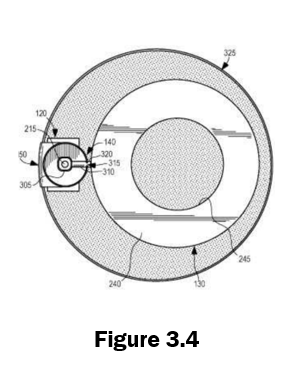
- US2019375177 (A1) (Figure 3.4) - Universal Trash Compacting Mechanism for Trash Receptacles
- Description: This patent introduces a universal compacting mechanism that can be attached to trash receptacles of various shapes and sizes. It includes a motor-driven threaded rod for compaction.
- Differences: Unlike this patent, our smart trash bin is a standalone unit, not designed as an add-on mechanism. Furthermore, our design integrates features such as fill-level detection, LED notifications (e.g., "Ready to Use," "Bin Full," and "Compaction in Progress"), and advanced safety mechanisms to pause operations if the bin door is opened mid-process.
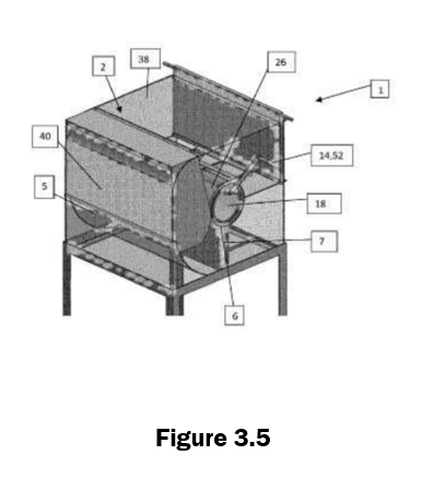
- DK201700154 (A1) (Figure 3.5) - Compacting Apparatus and Method for Compressing Waste Material
- Description: This patent focuses on a compacting apparatus with an arcuate front wall and a compression plunger that moves along a circular arc.
- Differences: Our smart bin features a straight vertical compaction path using a scissor-lift mechanism, contrasting with the circular arc motion described in this patent. Additionally, our design places emphasis on safety and electronic protection, features not emphasized in this patent.
- US10596775 (B2) (Figure 3.6) - Trash Compactor System with Improved Debris Handling
- Description: This patent describes a trash compactor system that integrates a mechanism for debris handling and a protective structure to prevent liquid seepage into sensitive components.
- Differences: While this patent focuses on debris management, our design goes a step further by positioning electronics at the top of the bin, entirely away from the compaction area, thus offering superior protection. Additionally, our scissor-lift compaction mechanism and integrated safety features, such as process pausing upon door opening, are absent in this design.
Conceptual Design


The Smart Bin aims to optimize waste management in fast-food by addressing several key functions. These functions include efficient trash compaction, user-friendly design, safety during operation, durability in harsh conditions and easy maintenance.
- Compaction force: the system must reduce the volume of waste efficiently via a mechanical system
- Safety: the system must include features that ensure safe operation, especially during compaction.
- Liquid management: to prevent the liquid damaging the electronics or interfering with the compaction mechanism.
- Ease of use: the bin should be simple to operate for customers with clear indications.
- Maintenance: the bin should be easy to maintain, including cleaning, trash bag replacement.
- Power supply: the bin must operate continuously
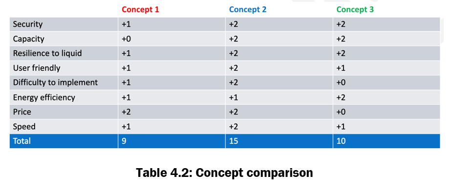
The Table 4.1 shows our morphological chart with 3 concepts generated
Our concept generation process was structured and iterative
- Ideas generation for each feature
- Smart bin mechanism study in existing products, analyzing their strength and limitations
- Exploring several mean to achieve each feature
- Multiples sketches to visualize and refine potential designs
- Generation of 3 concepts and made final sketches
Based on the comparative table shown on Table 4.2, concept 2 emerges as the most promising option, scoring the highest in safety, liquid resilience, user-friendliness and cost-effectiveness. The design is well suited for the goals of the project: it optimizes customers and workers satisfaction, provides reliable compaction, and integrates into fast-food environment.
- Scissor lift with linear actuator provides a robust yet energy efficient method to achieve high compaction force. The design ensures a good balance between the pressing force and the speed of operation.
- Lock during compaction prevent access during compaction
- Vertical compaction ensures more trash capacity
- Pull-to-open door prevent the door to interfere with the compacting mechanism
- Fill level at a certain level permit to place the sensor on the side of the bin
- Liquid management is ensured by putting all electronic components in a separate room
- Battery power supply offers reliable and cos-effective operation
- Ultrasonic sensor is chosen for its precision and reliability
- Compaction completion with current sensor ensures that the system stops compacting once the required force is achieved to prevent overloading.
Embodiment Design







CAD model and subsystems
The CAD model of the prototype that is built can be found in Figure 5.1. In Figure 5.14 can also be found the original CAD model made before starting the manufacturing process, as it can be seen several changes had to be done due to availability of materials or poor decision making. From now on it will only be described the model shown in Figure 5.1, which corresponds to the real prototype. It is divided in 6 subsystems, which are described below:
1. Compression mechanism
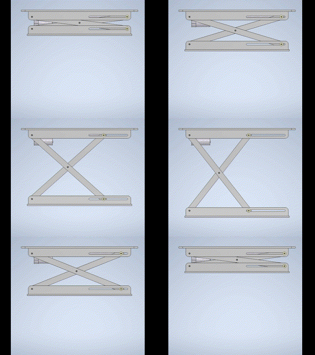
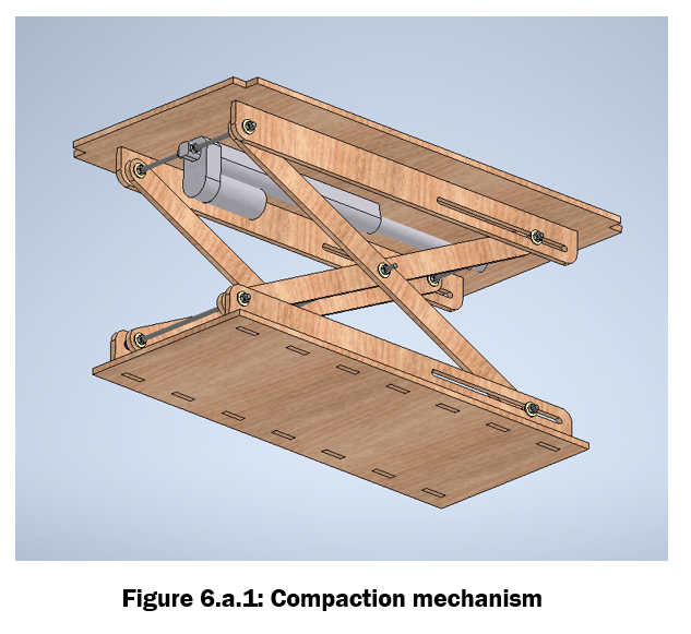
The compression mechanism is determined as a one stage scissor lift. These types of mechanisms transform a linear displacement of a linear actuator (also called stroke) into a greater displacement in a perpendicular direction of the mechanism. In other words, increases the stroke of the mechanism, reduces the force and changes the direction of displacement. In Figure 5.2 it can be seen the design of the compression mechanism of our project (the grey part is the linear actuator), one end is fixed to the structure and the other end is the compression plate that is in touch with the trash.
The next figure is a gif that illustrates the functioning of the mechanism. It can be seen that there are 3 pivot joints and 2 other sliding friction joints. The detail of the joints can be seen on Figure 5.3: the parts in yellow are washers and flanged plain bearings made out of a low friction mechanism (such as nylon) and the part in blue is a spacer sleeve to correctly place the scissor arms.
The dimensions of the mechanism chosen for the project can be seen in Figure 5.4. The minimum geometry to define the kinematics of the mechanism are the dimensions b, c and h. c also corresponds to the stroke of the actuator. In the design phase there were two different actuators to choose from:
- Stroke of 200 mm and 750 N force
- Stroke of 100 mm and 900 N force
Both with similar travel speeds and powers. It was decided to use Option 1, 200 mm stroke, in order to obtain a greater displacement in the scissor lift, and to be able to make a deeper trash bin in which more garbage can fit. It also features a speed of 20 mm/s, so it takes around 20 seconds for the mechanism to expand and retract.
The deduction of the equations of the kinematics and dynamics of the mechanism is outside the scope of this report. A reference page for its calculation can be found here, and the Matlab script created to do the calculations can be found in the project file repository under the name MechanismForces_MECHX.m.
The results of the kinematics and dynamic performance of the mechanism is shown on Figures 5.5 and 5.6. To read these graphs it is important to take into account that when the actuator (X axis) is fully extended (200 mm) is when the mechanism is retracted. Several things can be concluded out of these results:
- The compression force keeps increasing while the mechanism expands (Figure 5.5). This a good result, as in our design, the mechanism starts advancing without resistance and it is not until the last range of the mechanism displacement when it encounters trash (and therefore resistance).
- The reaction at point B (the sliding joint) can get as high as 800 N. Knowing the coefficient of friction, the force friction could be calculated.
2. Fill level sensor
The sensor that indicates the level when the mechanism should start compressing is a ultrasonic sensor located in the outer structure as shown in Figure 5.7. It is able to see through the trash bis because a hole is made for that purpose. A more in detail explanation of this system can be found in the next section 6. Design of subsystems.
3. Door opening
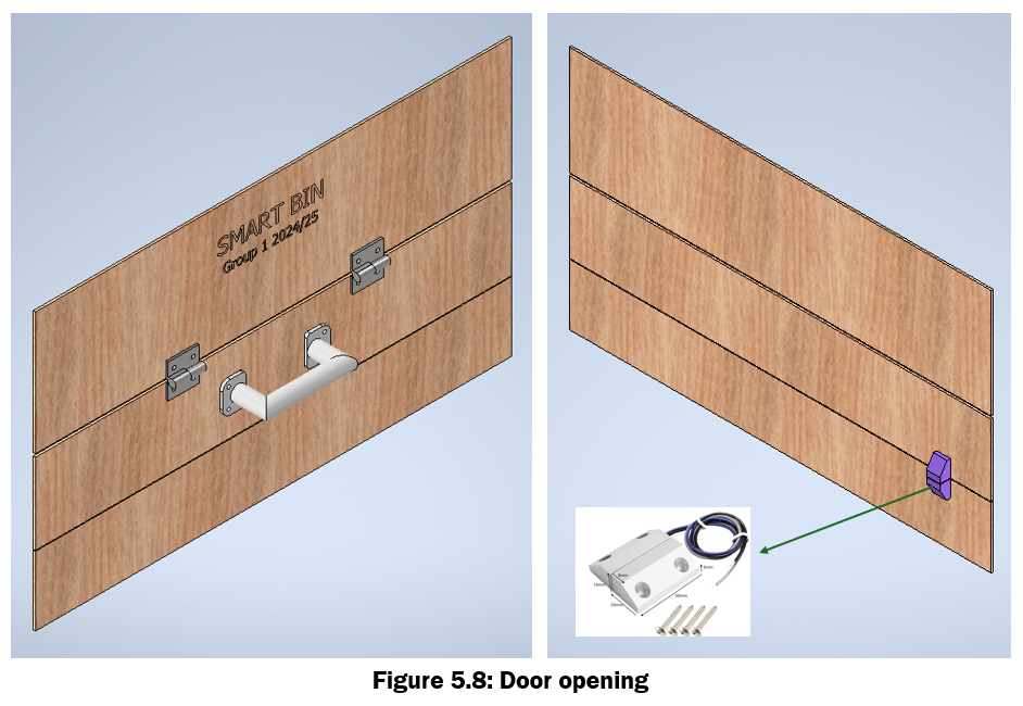
The door to introduce the trash. It can be seen in Figure 5.8. It features a magnetic sensor to detect if the door is open in order to stop the compression, as a safety system. Again, a more in detail explanation is given in the next section. This is the case for all of the electronics and sensors.
4. Electronics
In Figure 5.9 is shown a box where all of the electronics are contained. This includes the microcontroller, power supply, motor controller, etc. The box is placed on top of the mechanism, and in the same side where the linear actuator, ultrasonic sensor and magnetic sensor are placed, to be able to conduct the wiring through the same place.
5. Outer structure
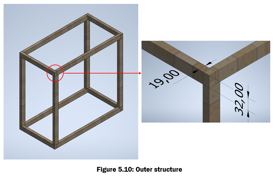
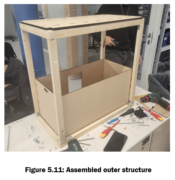
It is the subsystem that hold the rest of the subsystems in place. As it can be seen in Figure 5.14, originally it was going to be made out of aluminium extruded profile 20x20, but due to not having enough available material, it had to be changed to rectangular wood bars. In Figure 5.10 it can be seen a detail of the joints, and in Figure 5.11, the real outer structure already finished. The dimensions are 620x320x605 (Width x Depth x Height).
6. Trash bin
This detachable trash bin (Figure 5.12) allows the compressing mechanism to tightly compress all of the trash that is contained inside. It features around 40L of capacity. It also features a small transparent window made out of plexi in order to be able to see the trash being compressed.
High level block diagram
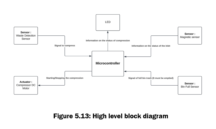
The high level block diagram can be found in Figure 5.13.
Material and manufacturing process selection
Disclaimer: Based on the guidelines for the report provided in Notion (they talk about "industrialisation" and "product"), we understand that these subsection requieres to talk about the material selection and manufacturing process of the final product, not the prototype. Material selection and manufacturing of the prototype will be addressed in the next section 6: Design Of Subsystems.
As this explanation contains several equations, and the Instructables platform does not support this format, it was decided to explain this subsection in the PDF named MaterialSelection_MECHX.pdf, available in the supporting files of this section and in the file repository of the project.
Downloads
Design of Subsystems






Disclaimer: In this section it will only be talked about the prototype, not the final product.
a. Mechanical Systems
1. Compaction mechanism
This is the main and most demanding mechanical system. It can be seen in Figure 6.a.1 of the section. The forces it have to withstand while compressing are quite high (they were calculated and explained in the previous section), so after a couple tests with the available materials in the Fablab (basically MDF of 3 mm or 4 mm), it was determined that a thicker material was needed to avoid buckling or tearing. The first option was to stack 3/4 mm sheets or buy a thicker one. For simplicity and to improve tolerance of fittings, it was decided to use a bought 8 mm MDF sheet. It was quite challenging to cut it with the available laser cutters, but with 2 mm/s speed and reducing the focal distance to 10 mm it was achieved.
The main structural parts of this system are named (Figure 6.a.2):
- Scissor Plate Upper (x1)
- Scissor Plate Lower (x1)
- Scissor Slider (x4)
- Scissor Structure Arms (x4)
As mentioned, all of these parts are made out of 8 mm laser cutted MDF, as they are plane pieces and need to withstand forces.The scissor sliders were glued together (Figure 6.a.3) to the corresponding upper/lower scissor plates .
Other parts to allow the movement of the mechanism are:
- Linear actuator (x1)
- Threaded rods M6 (x5)
- Spacers (x4)
- Plain bearings (x20)
- Thrust washers / Low friction washers (x20)
- Nuts M6 DIN 934 (x24)
The linear actuator was provided by the Fablab, so most part of the decisions surrounding this part are defined by it's geometry.
The rest of the parts mentioned above allow the pivoting, rotating and sliding of the mechanism. Using threaded rods was the simplest way of holding the structure together and allowing relative rotation of the mechanism. The chosen diameter (M6) was the maximum allowed by the already made holes on the linear actuator. (Figure 6.a.4)
Friction in a mechanism that withstands forces is crucial. The plain bearings and thrust washers were, at first, intended to be commercial parts made of a specific plastic material that reduces friction. This were to be provided by Igus, a German company that distributes these types of components for specific applications in robotics and automation. However, after a talk with the Fablab staff, it was determined that the cost of those parts were excesive for the use we were going to give them, so the plain bearings were 3D printed out of PLA and the thrust washers were substituted by wide flange washers (DIN 9021 M6, made out of regular steel). The joints were lubricated with lithium grease made for bearings, so friction could be brought down to a minimum.
2. Outer structure
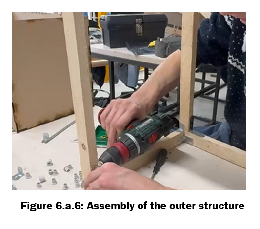
As mentioned on Section 5: Embodiment Design, the outer structure was originally going to be made out of aluminium extruded profile 20x20 to give the prototype more stiffness and to allow easy mounting of extra features on the outside. It would also allow to be the outer structure reusable: just disassembly the whole prototype when the course is finished and use the profiles for future projects. However, the Fablab did not have enough profiles to build the entire structure, and it was to expensive for the team to buy them. Therefore, it was decided to buy 19x32 wooden bars and brackets, mounted as seen in Figure 6.a.6. Finally, approximately 6 meters of wooden bar were used.
This allows some ease of disassembly, as wood screws can be mounted/unmounted several times, but the structure ended up lacking stiffness and most importantly, geometrical tolerances. The trash bin should fit snugly inside the outer structure, but in our case it ended up fitting too tightly, with no room for adjustment.
3. Trash bin
The trash bin is a simple box that allows the mechanism to slide in and compress what is in it. It has no mechanical requirements, so it was decided to use the lightest/cheapest material available at Fablab, MDF 3 mm. A small rectangular hole was left so, for the prototype, the user could see how the trash is being compressed. For the trash to not go out, it was covered with transparent plexi. See Figure 6.a.7.
b. Circuitry & Sensors
In this section, the choice of the different sensors is detailed. Let’s start with what is expected from the sensors. The sensors are supposed to work as follows:
- A first sensor monitors the bin by measuring the distance between itself and the opposite side of the bin. If this distance is approximately equal to the length of the bin (60 cm in the case of the prototype), it means the bin is empty.
- If this value changes to a distance between 2 cm and 60 cm, it indicates that trash is obstructing the signal, so the compaction process begins. But before the compaction begins, it checks if a second sensor is detecting the door of the bin or not. This sensor is called the security sensor. It makes sure the compaction does not start when the door is open so the user cannot be hurt. If the door is closed, the compaction starts and can be interrupted anytime if the door opens during the compaction. A motor driver then controls the linear actuator and retracts or extends it depending on whether the compaction is extending or retracting.
- After compaction finishes:
- If the sensor still detects an obstruction, it means the trash wasn’t compacted properly, and the bin is full.
- If the sensor detects the original length of the bin again (60 cm), it means the compaction was successful, and the process can repeat.
- Finally, some LEDs provide information about the state of the bin to the user/owner.
Design process and considerations of components
1. Distance sensor
The main challenge with the sensor was finding one capable of detecting restaurant trash such as cardboard boxes, cans, bottles, or plastic bags. Two choices emerged for the sensor: using a light sensor like a LIDAR or an ultrasonic sensor. Initially, the choice was made to use a LIDAR, as it seemed that this type of sensor would work well. However, this approach raised two issues.
First, the available LIDAR in the fab lab was a CamSense_X1, a LIDAR integrated with a servomotor, which added unnecessary complexity to the prototype. Second, in our application, some trash could be transparent, such as plastic bottles. Under certain conditions, the reflection of the light signal could either be refracted or return with too low an intensity. Although these problems were real most of them could have been solved with a different LIDAR sensor.
Meanwhile, the second type of sensor, the ultrasonic HC-SR04, was used for initial tests and appeared to work perfectly. Tests were conducted to identify any potential issues with this sensor. First, the measurement range was analyzed. Even though the datasheet specifies a measurement range of 2 cm to 400 cm, in the context of the smart trash bin prototype, only a range of up to 65 cm was necessary. After some basic tests, it became clear that the sensor was functioning as required.
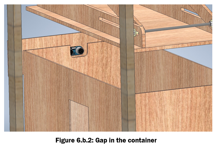
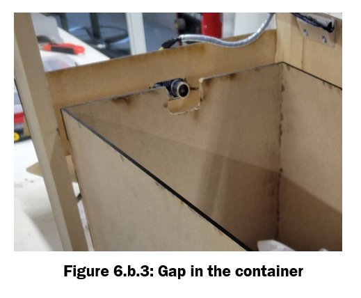
The sensor was place on the outer structure (see Figure 6.b.1).To integrate the sensor into the prototype effectively, a gap matching its dimensions was designed in the outer structure of the trash container to allow the ultrasonic signal to pass through and detect the trash (see Figure 6.b.2 and 6.b.3). This design introduced additional potential risks.
- The container must always be well-aligned in the bin so that the signal can pass through the gap. Fortunately, this alignment is already required for the compaction mechanism.
- The ultrasonic sensor in the prototype is in direct contact with the trash and cannot be protected with a transparent plate, as is possible with a LIDAR, due to the nature of the signal. While this is not a major issue in the prototype, for the final product, a LIDAR with transparent protection could be a more robust solution.
Regarding the sensor's integration into the circuit, the HC-SR04 requires a 5V supply, which is connected to the Arduino's 5V output in our setup. The sensor has two pins for communication: the trigger pin, used to initiate the measurement process, and the echo pin, which receives the reflected ultrasonic signal. These pins were connected to pins 7 and 8 of the Arduino, respectively. Finally, the sensor is, of course, connected to the Arduino's ground.
To conclude, regarding the current prototype, an HC-SR04 ultrasonic sensor was implemented. Most of the challenges related to its integration were successfully overcome. However, for a final prototype intended for the commercialization of the smart bin, a LIDAR sensor could provide a more robust and reliable solution.
2.Security Sensor
For the security sensor, the choice was made to use the magnetic reed switch MC-56. Its functioning is simple to use: basically, it is composed of two reeds slightly apart when the switch is in its default state. If there is a presence of a magnetic field, this field causes the reeds to attract each other when the door is closed, closing the circuit. When the door is open, the magnet is absent, and thus the circuit is broken.
These kinds of sensors are reliable, durable, and easy to implement, which is why they were chosen. The sensor is connected to the ground and the VCC of the Arduino and to pin 2 of the Arduino.
3.Motor Driver
The motor driver available was the XY-160D Motor Driver. It controls the linear actuator by reversing the polarity to either extend or retract the linear actuator. It has three ports: one port connects to the Arduino for signaling, the second port connects to the 12V power supply, and the third port connects to the linear actuator.
4.LEDs
Lastly, some LEDs were added to the prototype to inform the user or owner of the bin's current state. Three colored LEDs were implemented in the prototype:
- A green LED indicates that the bin is ready for use.
- A yellow LED is active during the compaction process.
- A blue LED signals that the bin is full.
To make the LEDs functional, 220-ohm resistors were used, and three pins, pin 11 for the green LED, 12 for the yellow LED and 13 for the blue one, were assigned on the Arduino.
The circuit diagram is show in Figure 6.b.4. and the exact components list is:
- Ultrasonic sensor: HC-SR04
- Magnetic sensor: magnetic reed switch MC-56
- Motor Driver: XY-160D
- 3 LEDs
- 3 resistor 220 ohm
- Arduino Uno
c. Software
To achieve the desired functionality of the Smart Trash Bin, various software tools, libraries, and configurations were utilized. The Arduino IDE served as the primary platform for writing, compiling, and uploading code to the Arduino Uno microcontroller. Its features, such as syntax highlighting for C++ programming, an integrated serial monitor for real-time debugging and monitoring, and seamless library integration, facilitated efficient sensor and motor driver control. The project was programmed entirely in C++, leveraging functions, loops, and conditionals to create a modular and efficient control logic.
The serial monitors within the Arduino IDE played a crucial role in debugging and monitoring sensor readings to ensure smooth operation. Key debugging functionalities included distance measurements from the ultrasonic sensor, status updates from the magnetic reed switch (indicating door open or closed), actuator states (extending or retracting), and full bin status alerts. For hardware-software integration, proper pin configuration in the code enabled the seamless connection of various components with the Arduino Uno. These included the motor driver (XY-160D) for controlling the linear actuator during the compaction process, the HC-SR04 ultrasonic sensor for measuring trash levels, the magnetic reed switch for detecting door status, and LED indicators for displaying system states such as Ready, Compaction, and Full Bin.
Example Pin Connections can be found in Figure 6.c.1.
The Smart Trash Bin incorporated robust power supply monitoring and precise timing functions to ensure reliable and efficient operation. The Arduino was configured to function seamlessly with power inputs converted from 12V to 5V using a DC-DC converter, guaranteeing uninterrupted operation of the system. For enhanced functionality, millis-based timers were utilized, enabling accurate timing for various tasks. These timers facilitated continuous monitoring of the ultrasonic sensor, controlled the duration of the compaction operation, and implemented delays for rechecking the bin's status, ensuring optimal performance and responsiveness.
The design of the Smart Trash Bin involved extensive consideration of software logic and integration to ensure seamless operation of all hardware components. The software design was centered around creating an efficient, reliable, and modular codebase using the Arduino IDE, programmed in C++. Below is an overview of the software design process and considerations for each component:
- Ultrasonic Sensor (HC-SR04): The software logic for the ultrasonic sensor utilized precise timing functions to measure the time taken for sound waves to return after being triggered. This was achieved using the Arduino's pulse in function to calculate the distance to the trash level in real-time. Threshold values for bin fullness were defined and stored as constants in the program for quick calibration and accuracy. The software ensured noise filtering by averaging multiple readings to minimize errors caused by environmental factors.
- Linear Actuator Control: The compaction process was implemented through software control of the motor driver connected to the linear actuator. Using pulse-width modulation (PWM) signals, the software managed the actuator’s extension and retraction. Safety mechanisms were embedded in the code to pause the actuator's motion if the magnetic reed switch detected the door opening mid-operation. Timer-based delays ensured precise timing of the compaction process.
- Magnetic Reed Switch: The software continuously monitored the state of the reed switch through Arduino’s digital input pins. A state-change detection algorithm was implemented to immediately trigger a compaction pause when the door opened. This logic ensured safety and user convenience without affecting other system operations.
- LED Indicators: The status LEDs were controlled using simple digital HIGH and LOW signals. The software mapped system states (e.g., Ready to Use, Compaction, Bin Full) to corresponding LED outputs. This ensured real-time feedback for the user through clear visual signals. State transitions were implemented using an efficient state machine approach for consistent behavior.
- Power Management and Timing: Software considerations for power management included optimized use of timers and minimal active processing when the system was idle. The Arduino’s millis() function was employed for non-blocking timing operations, ensuring smooth multitasking for sensor monitoring, compaction control, and user interactions. This approach eliminated the need for delay-based blocking code, enhancing system responsiveness.
- System Safety and Recovery Features: Safety protocols, such as pausing compaction when the door was open, were implemented in the software to prevent hardware damage and user injury. Additionally, fail-safe mechanisms were coded to handle unexpected scenarios, like power loss or sensor malfunction. Upon power restoration, the system resumed from its last stable state, ensuring reliability.
- Code Modularity and Maintainability: The software was written in a modular structure, with separate functions for each hardware component. This approach enhanced readability and maintainability, making future upgrades or debugging simpler. Critical parameters, such as bin depth thresholds and actuator timing, were defined as variables for easy adjustments during calibration.
By focusing on software integration and control, the Smart Trash Bin’s operation was streamlined to achieve efficiency, safety, and user-friendliness. The software design complemented the hardware, ensuring all components functioned cohesively as a unified system.
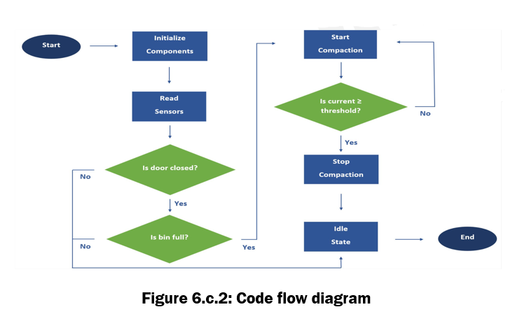
The code flow diagram can be found in Figure 6.c.2.
Testing ensures that the Smart Trash Bin functions as intended under various scenarios. The following aspects were evaluated:
1. Component Testing
- Ultrasonic Sensor (HC-SR04):
- Verified the sensor’s ability to measure distance accurately under different lighting and trash levels.
- Tested for responsiveness with objects placed at varying distances.
- Result: Sensor consistently measured distances with an accuracy of ±1 cm.
- Magnetic Reed Switch:
- Tested door open/close detection at different speeds and positions.
- Ensured the sensor paused the compaction process when the door was open.
- Result: Switch successfully detected door states and triggered the compaction pause feature.
- Linear Actuator:
- Tested the linear actuator for precise and smooth movement during the compaction process.
- Ensured it stopped and resumed correctly when the magnetic sensor detected the door opening or closing.
- Result: Actuator operated seamlessly under a 12V power supply, lifting and compressing trash effectively.
- LED Indicators:
- Verified the functionality of the Ready to Use, Compaction, and Bin Full LEDs.
- Checked proper synchronization with system states.
- Result: LEDs accurately reflected the system’s current state.
2. Functional Testing
- Trash Detection and Compaction:
- Simulated various trash levels to test the transition between Ready to Use, Compaction, and Bin Full states.
- Ensured compaction only occurred when the bin was full.
- Result: System transitioned smoothly between states based on real-time trash levels.
- Power Supply Testing:
- Verified stable operation under 220V AC to 12V DC conversion.
- Ensured Arduino received 5V power consistently without voltage drops.
- Result: Power supply met all requirements for smooth operation.
- Interrupt Testing (Door Open Mid-Compaction):
- Opened the door while compaction was in progress to test the pause and resume functionality.
- Result: Compaction paused immediately and resumed correctly once the door was closed.
3. Debugging and Error Handling
- Scenarios Tested:
- Power failure during operation: Ensured the system resumed correctly upon restoration.
- Sensor malfunction: Checked if the system provided appropriate fallback states.
- Result: The system recovered gracefully in all tested failure scenarios.
The used code is provided below:
Integration Guide
This section outlines how the various subsystems and components of the Smart Trash Bin were integrated to function cohesively.
1. Subsystem Overview
- Sensors and Indicators:
- Ultrasonic sensor for trash level detection.
- Magnetic reed switch for door state monitoring.
- LED indicators for system states (Ready to Use, Compaction, Bin Full).
- Actuation System:
- Linear actuator controlled via a motor driver (XY-160D) for compaction.
- Microcontroller:
- Arduino Uno as the central processing unit to control and coordinate all subsystems.
- Power Supply:
- AC to DC converter supplying 12V for the motor driver and linear actuator.
- 12V to 5V DC converter supplying power to the Arduino Uno and sensors.
2. Step-by-Step Integration Process
Step 1: Power System Integration
- Connected the AC to DC converter to a 220V power source.
- Verified stable 12V DC output using a multimeter.
- Installed a 12V to 5V step-down converter to supply power to the Arduino Uno and sensors.
- Connected the 12V output directly to the motor driver for powering the linear actuator.
Step 2: Microcontroller and Sensor Integration
- Ultrasonic Sensor (HC-SR04):
- Connected VCC and GND to the 5V and GND pins of the Arduino.
- Connected Trigger and Echo pins to digital pins of the Arduino.
- Configured the Arduino to calculate the distance based on the sensor’s pulse time.
- Magnetic Reed Switch:
- Connected one end to the GND pin and the other to a digital input pin on the Arduino.
- Programmed the Arduino to monitor the door state and generate interrupts during operation.
- LED Indicators:
- Connected LEDs to digital output pins via 330-ohm resistors.
- Assigned each LED to represent system states (Ready to Use, Compaction, Bin Full).
Step 3: Motor Driver and Actuator Integration
- Connected the XY-160D motor driver to the Arduino:
- IN1 and IN2 pins connected to digital output pins on the Arduino for direction control.
- PWM pin connected to a PWM-capable pin for speed control.
- Wired the Linear Actuator to the motor driver output terminals.
- Tested actuator movement by sending directional signals (HIGH/LOW) from the Arduino to the motor driver.
Step 4: Programming and Logical Integration
- Code Deployment:
- Uploaded the Arduino code for system logic, including:
- Distance measurement and level calculation from the ultrasonic sensor.
- Door state detection and interrupt handling.
- LED state transitions based on operational conditions.
- Motor control signals for the linear actuator.
- Subsystem Coordination:
- Programmed the Arduino to monitor the bin level and activate the actuator when full.
- Added logic to pause compaction if the door opens (based on magnetic switch input).
- Ensured all LED indicators responded dynamically to their respective states.
Step 5: Physical Assembly and Wiring
- Mounted all components securely within the bin structure:
- Placed the ultrasonic sensor at the right side to face the trash level.
- Installed the magnetic switch at the door .
- Mounted the linear actuator and scissor lift mechanism within the bin for compaction.
- Routed wires neatly to prevent interference or accidental disconnection.
- Secured the Arduino, motor driver, and power supply in an accessible compartment.
Step 6: Integration Testing
- Powered on the system and verified stable operation of all components.
- Tested the interaction between subsystems:
- Confirmed ultrasonic sensor readings triggered the compaction process.
- Ensured the magnetic switch paused the actuator during door interruptions.
- Verified LED states transitioned appropriately during all operations.
3. Final Integration Checklist
- [✔️] All power connections verified for stability.
- [✔️] Arduino code tested for logical flow and real-time responsiveness.
- [✔️] Components mounted securely within the structure.
- [✔️] Subsystems tested individually and in unison.
- [✔️] Physical wiring inspected for durability and safety.
Demo Project Show
Downloads
Critical Review of the Project


Current sensor
A current sensor was ordered during the first Fablab sessions. It took a while to arrive, and when it did and the team had something to test with, the sensor ended up not being sensitive enough to detect the range of forces the linear actuator is supposed to work on. This means that the trash bin cannot detect how "strong" the trash that it is compacting is. So if the object to compress was something like a pool ball, the compressing system would probably break during the compression stage.
Door lock
Even tough the door lock arrived early and worked correctly, it ended up putting up too much resistance to close the latch. As the door of the prototype was made of 3 mm MDF, the door bent before the latch could engage. The lock could probably be implemented in the final product, but not in the prototype. Another problem is that the lock consumed current to keep it open, and in our project, the normal operation is for it to be open. This meant that it consumed power all the time except at certain times, which is not acceptable in terms of power consumption. In short, a normally closed latch was chosen when it should have been a normally open one.
Emergency button
An important safety feature that was inadvertently not included was an emergency stop button. This is essential for any system that interacts with humans or can cause potential harm.
Mechanism stiffness a M6 rods
Perhaps the biggest flaw that the prototype has is the stiffness of the compression mechanism. When the calculations were made of the forces that the structure had to withstand, they were made taking into account that everything would slide and move straight, that there would be no misalignments or variable disturbances during compression.
The calculations were made thinking especially about the arms of the structure, and that is why they were tested and it was decided to increase their thickness to 8 mm. However, nothing was tested or calculated for M6 threaded rods. When we were testing the entire prototype, taking it to more demanding conditions, we realized that the rods began to bend, as seen in Figure 9.1 and that they caused significant misalignments, which in turn caused the washers to tear the part of the slot through which the mechanism must slide, as seen in Figure 9.2.
All these problems came up when testing the final prototype, during the last two weeks of work in the Fablab, and constantly assembling and disassembling the entire mechanical part generated a workload and a bottleneck that made it impossible to properly test the electronic part of the project. These problems could have been foreseen in the time organization of the project, and that would have been the main point of improvement that would have made the prototype work flawlessly.
Sustainability
The development of the prototype uses mainly MDF and normal untreated wood, with a small amount of PLA from 3D printing. While MDF and PLA are hardly recyclable and largely non-biodegradable, the normal wood used for the outer structure is easily biodegradable or compostable. Moreover, as it has been used in long bars, it can be reused for future projects in the course.
In addition, the most complex, expensive and probably most carbon-intensive element, the linear actuator, was chosen from those available in the fablab, and the rest of the trash bin measurements were adapted to fit it. The prototype has therefore been designed around a component that has already been used by others, and will be used again in the future by others.
In evaluating the decisions made throughout the project and considering alternative options that could have been chosen with more time, money, or resources, there are several areas where sustainability can be improved.
- For the scissor lift system, instead of using wood, we could have selected a more durable material to enhance the overall longevity of the smart bin. This would ensure that critical components are replaced less frequently, thereby reducing waste by opting for materials with a longer lifespan. Additionally, wood is not ideal for the outer structure due to its difficulty in cleaning and its tendency to accumulate dirt over time, necessitating replacement of the material. This is no big deal because the prototype is set to last 2-3 months, but it would be if the lifespan were to be different.
- From an energy efficiency perspective, the system is designed to continuously monitor whether the bin is full, meaning the entire system always remains active. One potential improvement would be the implementation of a smart energy management system to optimize power usage and reduce unnecessary consumption.
Overall, while the Smart bin was designed with sustainability in mind, but there are still multiple opportunities to further reduce its environmental impact.
Bill of Materials



The BOM and cost calculations for the prototype can be found in the file CostCalculations_MECHX.xlsx in the project repository.
The BOM is also shown in Figure 11.4. Each part is given a unique number and differentiates between Bought or Made.
To calculate the cost of each part it is split between:
- M→ Material: The price of the raw material if the part is made or the price of the bought part.
- P → Process: The cost of the process to transform the raw material into final product.
- F → Fastener: Prices of comercial fasteners such as screws, nuts, washers, etc.
The prices for the Materials and Fasteners can be found in Figure 11.1, and were estimated based on prices available on brico.be or in other sites on the internet.
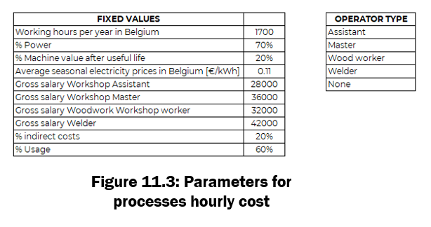
The price estimation for the Processes takes into account a lot more parameters, that are shown on Figures 11.2 and 11.3. The cost of a Process is basically divided in 3 parts:
- Labour cost: takes into account the type of operator (and therefore his salary) that carries out the process and other indirect costs such as taxes.
- Depreciation cost: takes into account the price of the machine, it's service life and depreciation over the years.
- Energy cost: takes into account power consumption of the process and energy cost.
There are many other parameters that are still being left out from the hourly rate for a process, such as the maintenance costs or the price of the surface the machine occupies.
As the prototype is mainly done using laser cutting and 3D printing, these are the only Processes considered, plus a third one that covers the machine set-up (loading the file, checking that everything starts working correctly, cleaning it...).
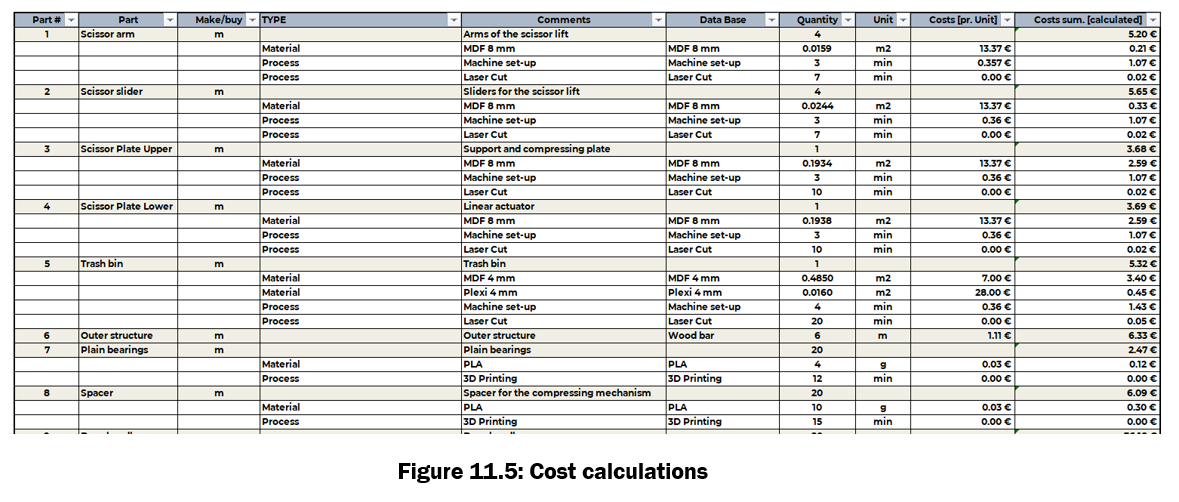
Finally, in Figure 11.5, it can be seen how the cost of every part is computed. The full table can be found in the excel file available in the repository.
The total calculated cost of the prototype is 165.33 €. It is kind of expensive, but it has to be taken into account that most of this price comes from the linear actuator and electronics, that can be disassembled and reused for future projects.
It is worth mentioning things that have not been computed into the price, but that should be taken into account if the product were to be commercialized:
- No process such as assembly, gluing, wiring have been included, even though they take a long time and the labour cost is a large part of the cost of a product.
- No price of failed laser cuts or 3D prints have been computed.
- The price of wires, glue, wood screws, grease and wire covers has been neglected.
Team Presentation
Hello, my name is Homa, and I am a former ULB student. I really enjoyed working on all the phases of this project, especially exploring the different ways to design it and researching the most promising solution. I worked a lot on the concept generation phase, which led us to the scissor lift design decision, and I also contributed to building the prototype. Additionally, I focused on the safety aspects of the project, ensuring that our design met the necessary requirements. The Fablab was a completely new experience for me, and I loved the hands-on environment, where we could develop our idea from start to finish. At the same time, it was interesting to face the challenges of time, resources, and costs. Through this project, I was able to learn so much that you don’t necessarily encounter in more theoretical courses. And with such a motivated team, it was a truly positive and enriching experience for me.
_______________________________________________________
Hi! I am Jorge and I studied a degree in mechanical engineering at the Technical University of Madrid (UPM). I am currently taking the BRUFACE programme as part of a double master's degree together with my university in Spain, where I have already completed one year of master's degree. I have a solid background in mechanical design, CAD modelling and simulation and workshop work with metallic materials. However, I had never tackled woodworking and laser cutting before, and it's something I've enjoyed a lot. Working with different thicknesses of material, modifying cutting parameters, testing tolerances, etc. In the project I have been mainly involved in the CAD design of the prototype and in its manufacture and assembly.
_______________________________________________________
My name is Awais, and I hold a bachelor's degree in Electrical and Electronics Engineering. I am currently pursuing a master's in Electromechanical Engineering with a focus on Robotics and Mechanical Construction through the BRUFACE program between VUB and ULB. In this project, I contributed to the software, microcontroller, and power supply management aspects, including circuit simulation, Arduino programming in C++, sensor integration, and power supply selection. I also managed the wiring and ensured proper insulation. I particularly enjoyed overcoming challenges such as implementing safety features and failure scenario recovery in the code and adapting to unexpected components when the exact parts we ordered were unavailable.
_______________________________________________________
My name is Liam, and I did my bachelor's at ULB. I really enjoy working in groups; it's cool to collaborate with people from different parts of the world. What I liked most about this project was discovering more about the real process of creation and trying to solve the problems we encountered during this process. In the project, I worked on various aspects, mainly focusing on the sensors and the assembly of the prototype.
_______________________________________________________
My name is Adrien, and I am a student who completed three years of a bachelor's program at ULB. Previously, I had the opportunity to work on an electromechanical project, which gave me some prior experience with FabLab. This project was incredibly fun to work on thinking through all the constraints and the logic behind the combined subsystems was both fascinating and rewarding.
What I enjoyed the most was putting everyone’s knowledge into practice to create a final object. In the project, I had the chance to work on designing the trash bin’s safety system. Additionally, I got to assemble it in practice and learned how to use a 3D printer, which I had never used before. This project was a fantastic learning experience, and I will apply what I learned in the future.
_______________________________________________________
Hello, I am Samir, and I am a student at the Polytechnic University of Valencia (UPV). I graduated with a degree in industrial engineering and I am studying at the ULB as part of the Erasmus program of my university in Spain. I had previous experience with workshop work and CAD design, so I was largely responsible for the 3D design of the model and the manufacture of the prototype. What I liked most about the project was being able to work alongside other groups, seeing how they executed their projects and being able to ask questions and explore other ideas.
Project Repository
Get access to the file repository in OneDrive through this link.
If any problem accessing (might happen for VUB accounts), please contact jorge.calvo.arroyo@ulb.be