Smart Arduino Energy Monitor | ESP32 + Raspberry Pi + Home Assistant
by mcmchris in Circuits > Microcontrollers
15609 Views, 58 Favorites, 0 Comments
Smart Arduino Energy Monitor | ESP32 + Raspberry Pi + Home Assistant
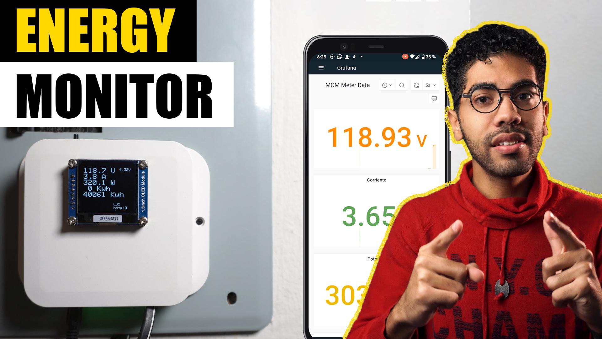
Hello to everyone, today I am going to show you a project that I've been working on for a while, it consist on an ESP32 based Smart Energy Monitor that takes current and voltage samples through sensors in our power grid and shares the data to a local server made with Home Assistant and Raspberry Pi.
If you are a visual learner I know that a video worth more than 1000 words, so here is a tutorial video. (I am a Spanish speaker, so please consider turning on English subtitles):
Skills Required
.png)
.png)
.png)
This project may seem difficult or very complex, but it is definitely not completely, since you will have all the guidance for the construction, it was difficult for me to design it to make life a little easier for you. Any conceptual doubt, you are free to ask it without problems.
You should have an understanding of:
- Basic electronics. (We are going to be using some electronics principles that are good to know to understand how this meter works).
- Handling of cutting tools and drills.
- How to solder. (To place the components we need).
- How to use a meter intruments as multimeters and clamp meters.
- Writing code in C. (if you want to make any modification to the main code that is provided).
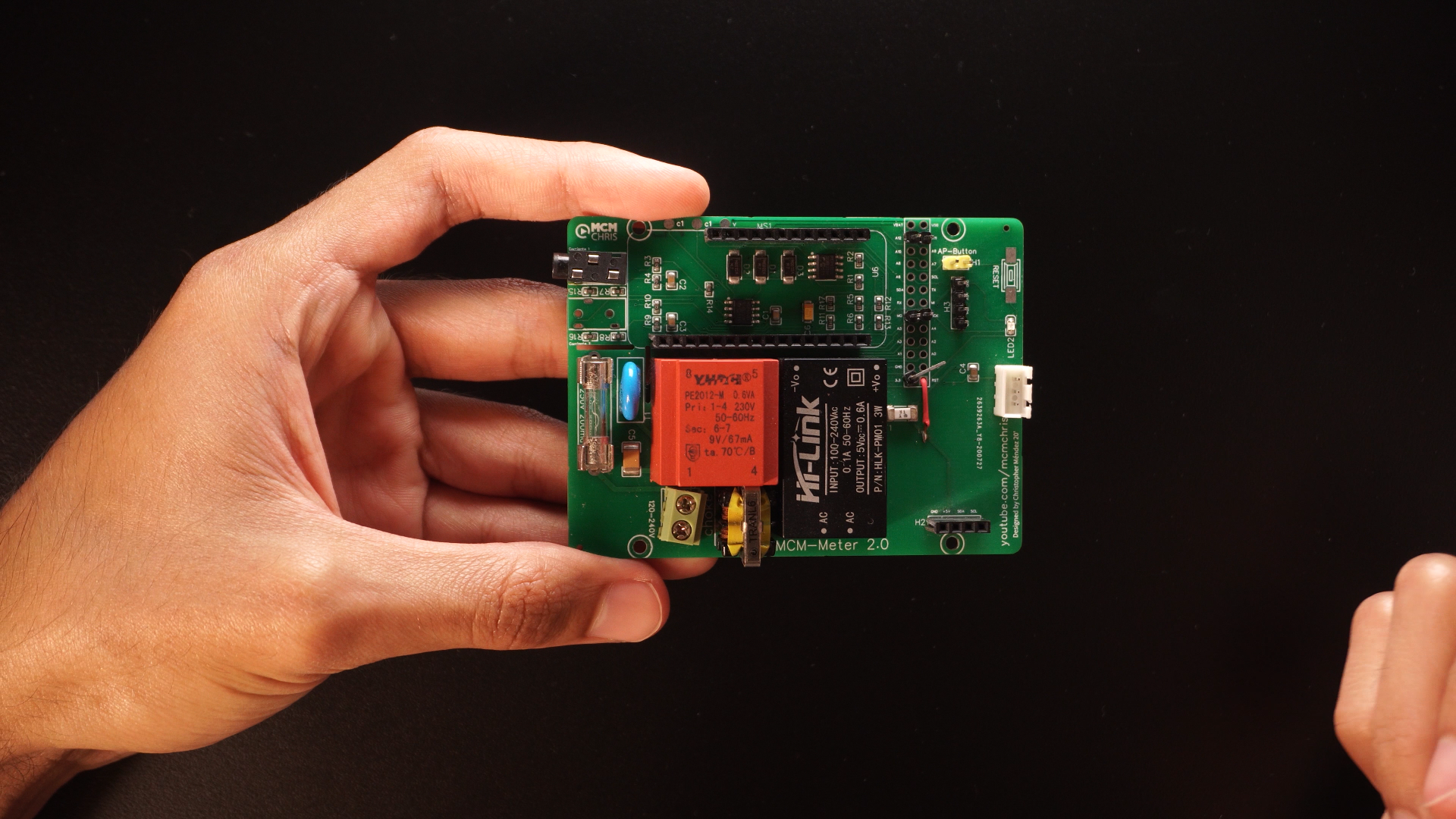
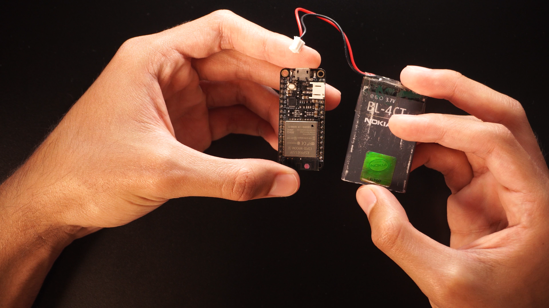
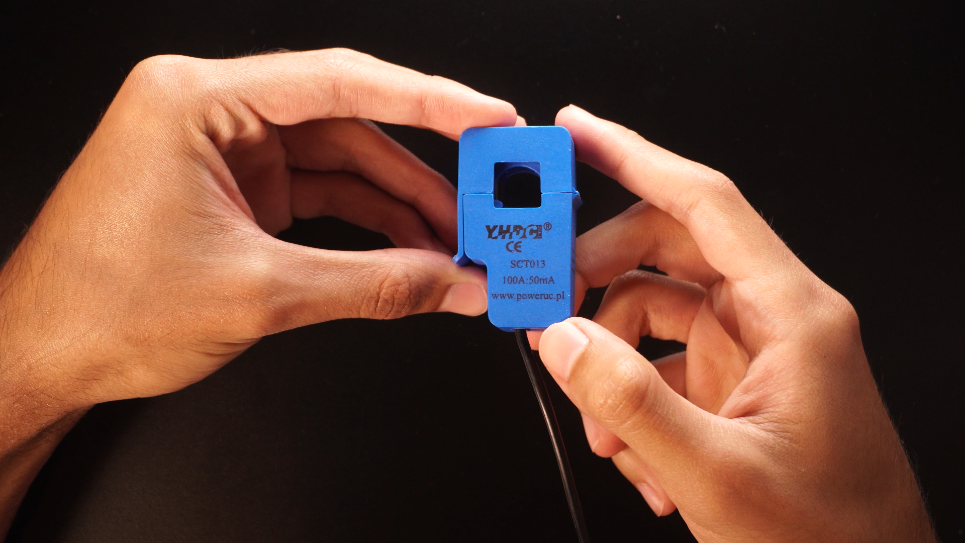
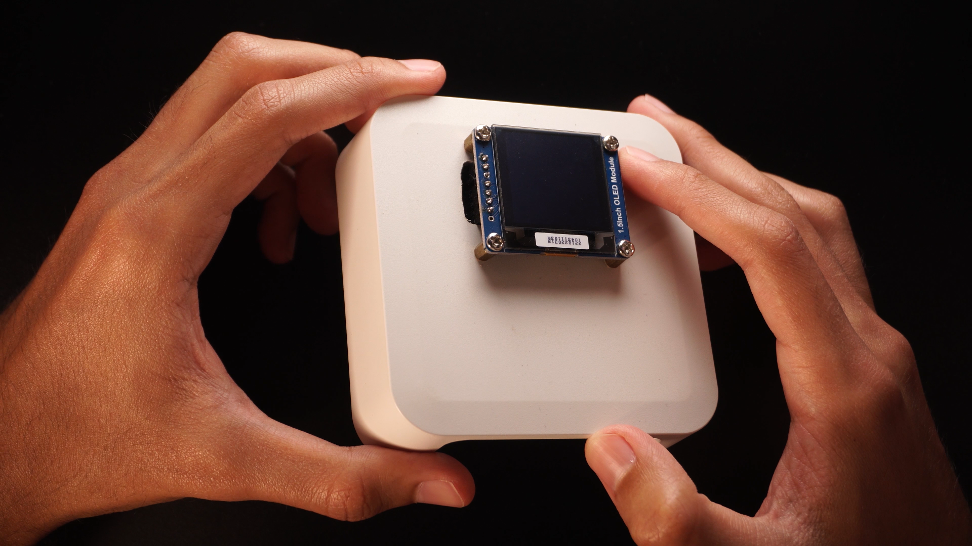
Components and Parts List
.png)
.png)
.png)
.png)
The electronics discrete components as resistors and transistors will be attached in a BOM file in the PCB Step.
🛒Materials:
- -Current sensor (CT)
- -Voltage transformer (PT) YHDC PE2012-M 230-9v
- -OLED Display
- -Adafruit ESP32 Feather
- -Audio Jack 3.5mm
- -SIL connector
- -Varistor, 240v-200ma fuse,choke coil.
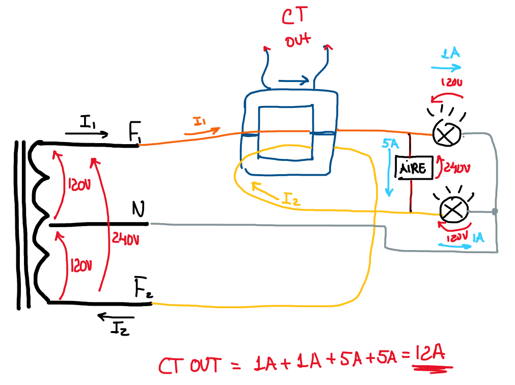
Circuit Diagram
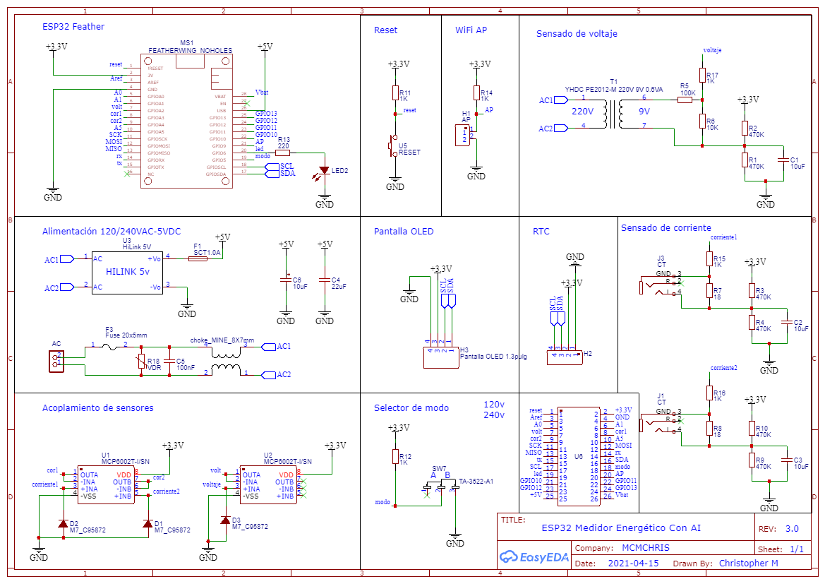
Here is the Circuit Diagram of our project:
It has all the internal connections of the circuit that will allow us to create the PCB design later.
I also attached the PDF of the Schematics so you can see it better.
PCB Design, Gerber, BOM and Pick & Place Order
.png)
For the implementation of a good project we need a reliable assembly for the circuit that makes it up, and there is no better way to do it than with a good PCB.
Here you can download the Gerber, BOM and Pick & Place Files, the ones you need to order your PCB on your PCB manufacturing company.
I suggest JLCPCB:
📦$2 for 1-4 layers PCBs ⚡ + 🎫 SMT Coupons
⏬Download Free Gerber, BOM and Pick & Place files
Un Zip de .rar file with a software like WinRar or any other.
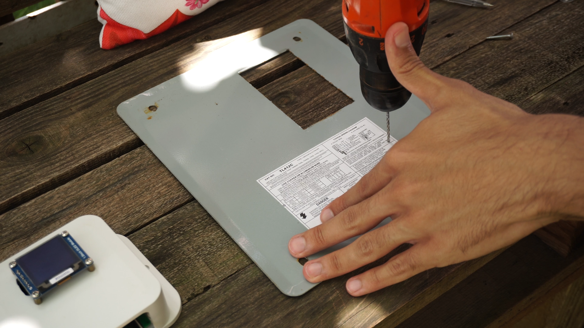
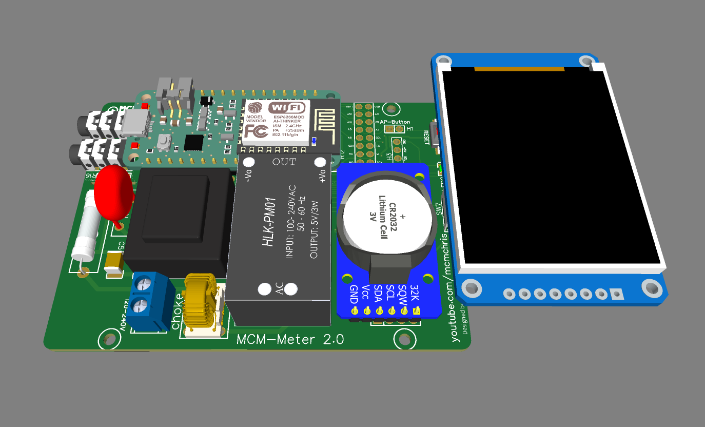
Project Enclosure (TAKACHI)
I request a free sample of this TAKACHI enclosure for my project, you can instead 3D print yours with the dimensions shown in the PDF.
Downloads
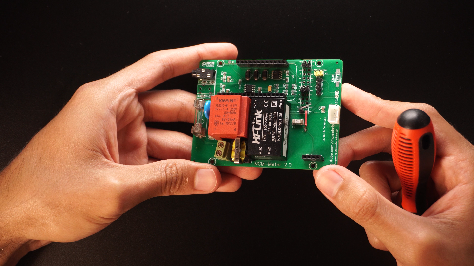
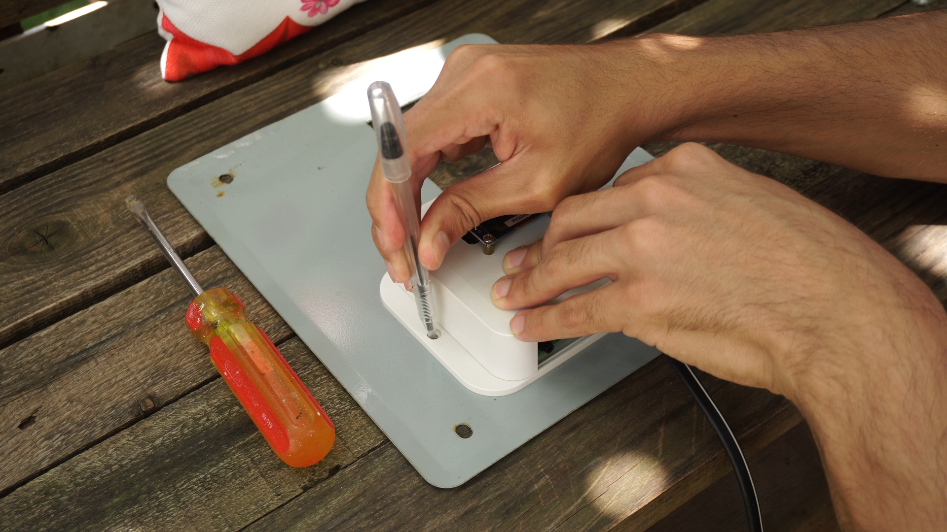
Assembly of the Board
.png)
.png)
.png)
.png)
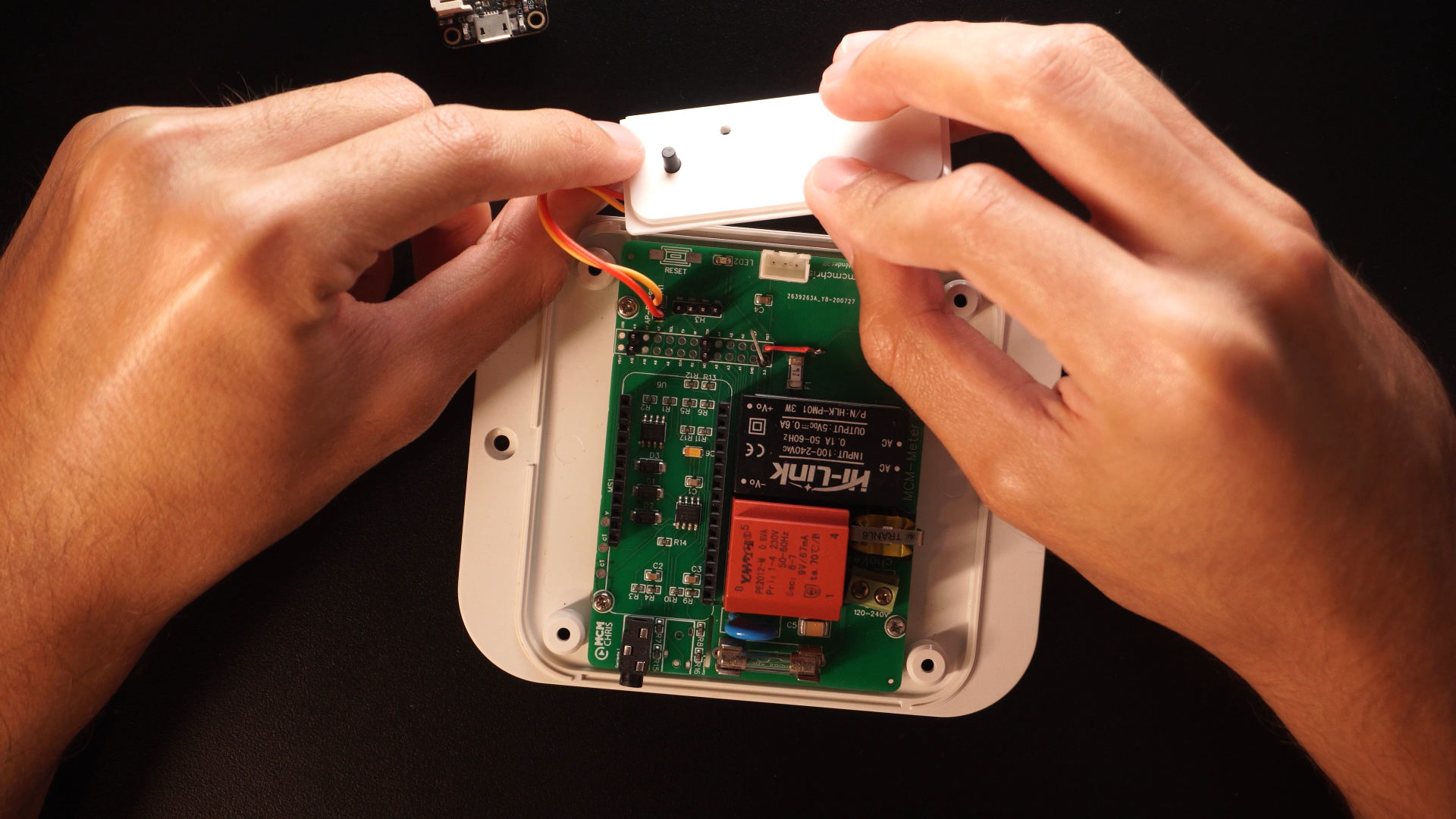
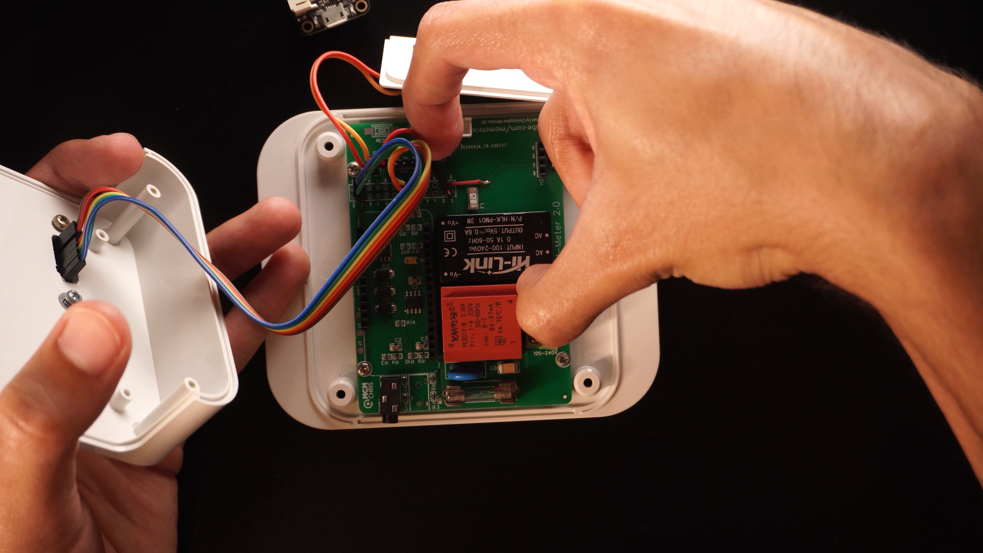
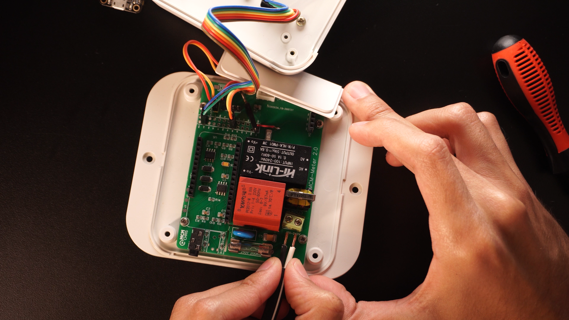
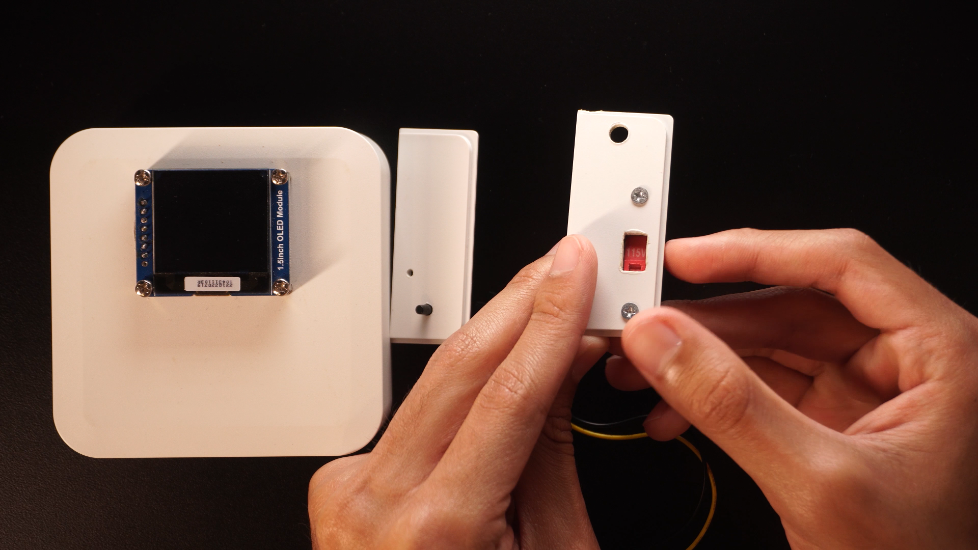
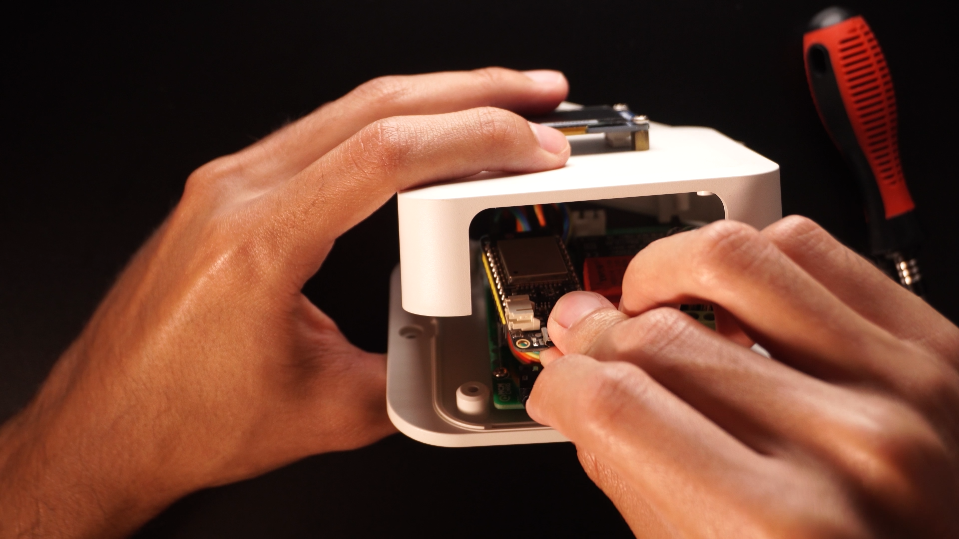
To start taking everything together follow these steps:
- Connect the push button to the PCB
- Connect the OLED display to the PCB, the code is made for the SPI configuration.
- Connect the AC cable in the PCB terminal block (strip wires)
- Connect the voltage selector switch
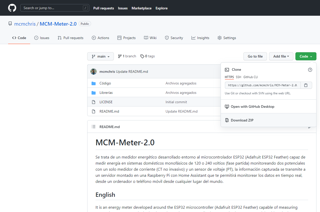
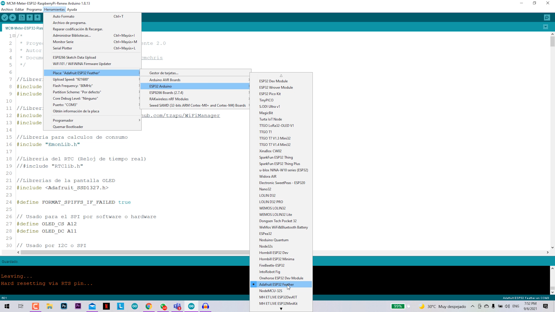
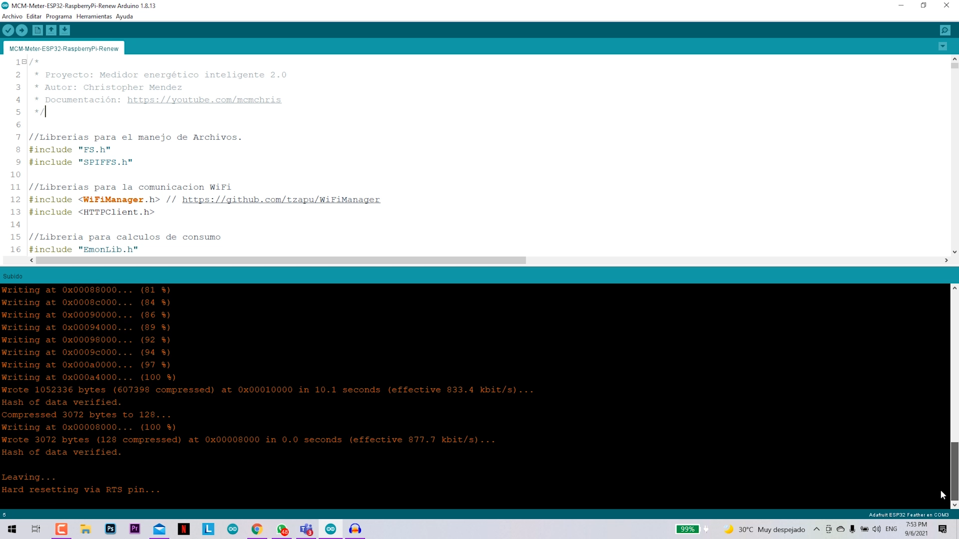
Programming the ESP32 (GitHub)
.png)
.png)
.png)
Go to my Github repository and follow these steps:
- Install the Arduino IDE
- Install the ESP32 card package by copying this URL in IDE preferences: https://dl.espressif.com/dl/package_esp32_index.j...
- Deploy your server in Home Assistant
- Clone this repository
- Install the attached ZIP libraries
- Open the Arduino code
- Modify the **Clavis** variable with a long-term Token generated in your Home Assistant
- Modify the variable **serverName** with "http://(IP of your Raspberry Pi):8123/api/states/sensor.meter_ai", Ex: "http://192.168.100.7:8123/api/states/sensor.meter_ai "
- Connect your ESP32 and load the program on the board
Configure the Home Assistant Enviroment
.png)
.png)
.png)
.png)
.png)
.png)
.png)
.png)
.png)
.png)
.png)
.png)
.png)
.png)
.png)
.png)
.png)
.png)
.png)
.png)
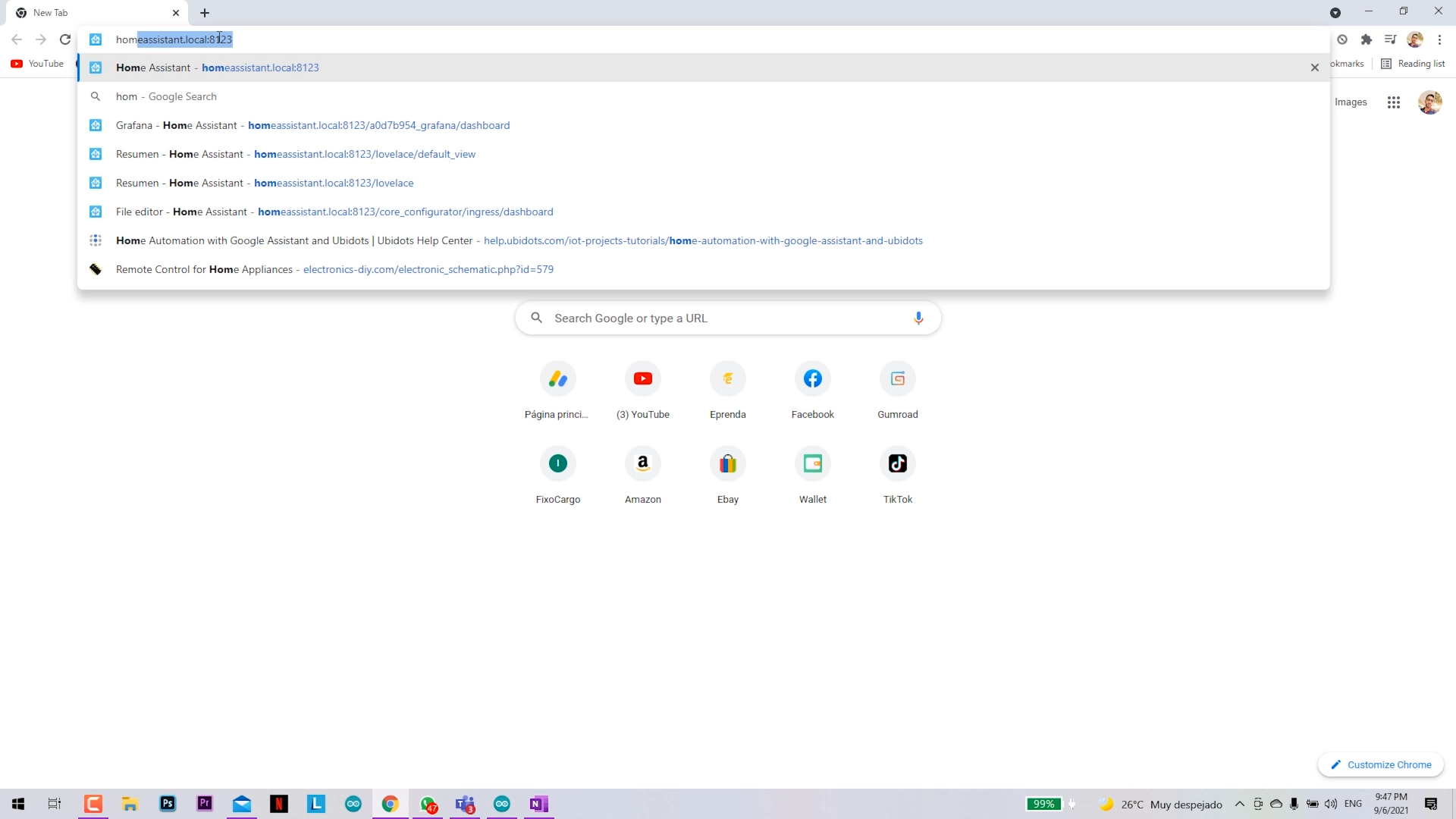
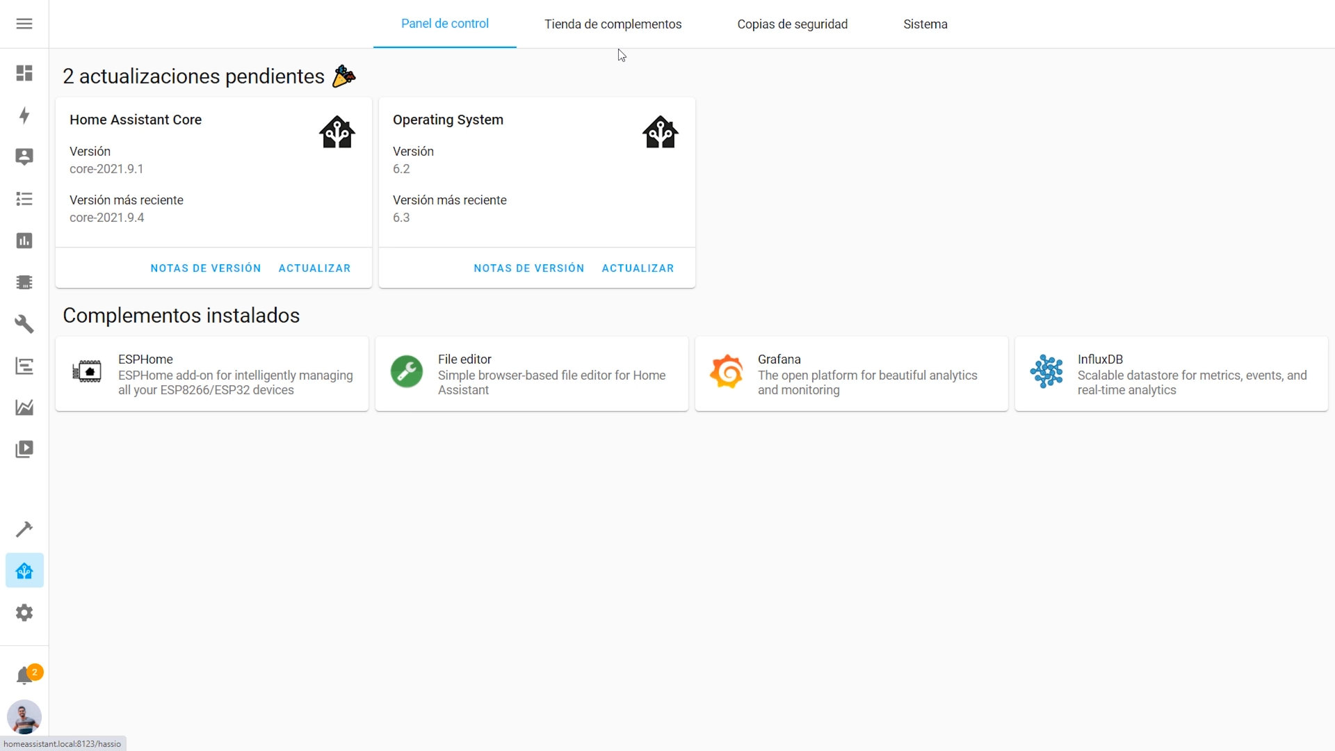
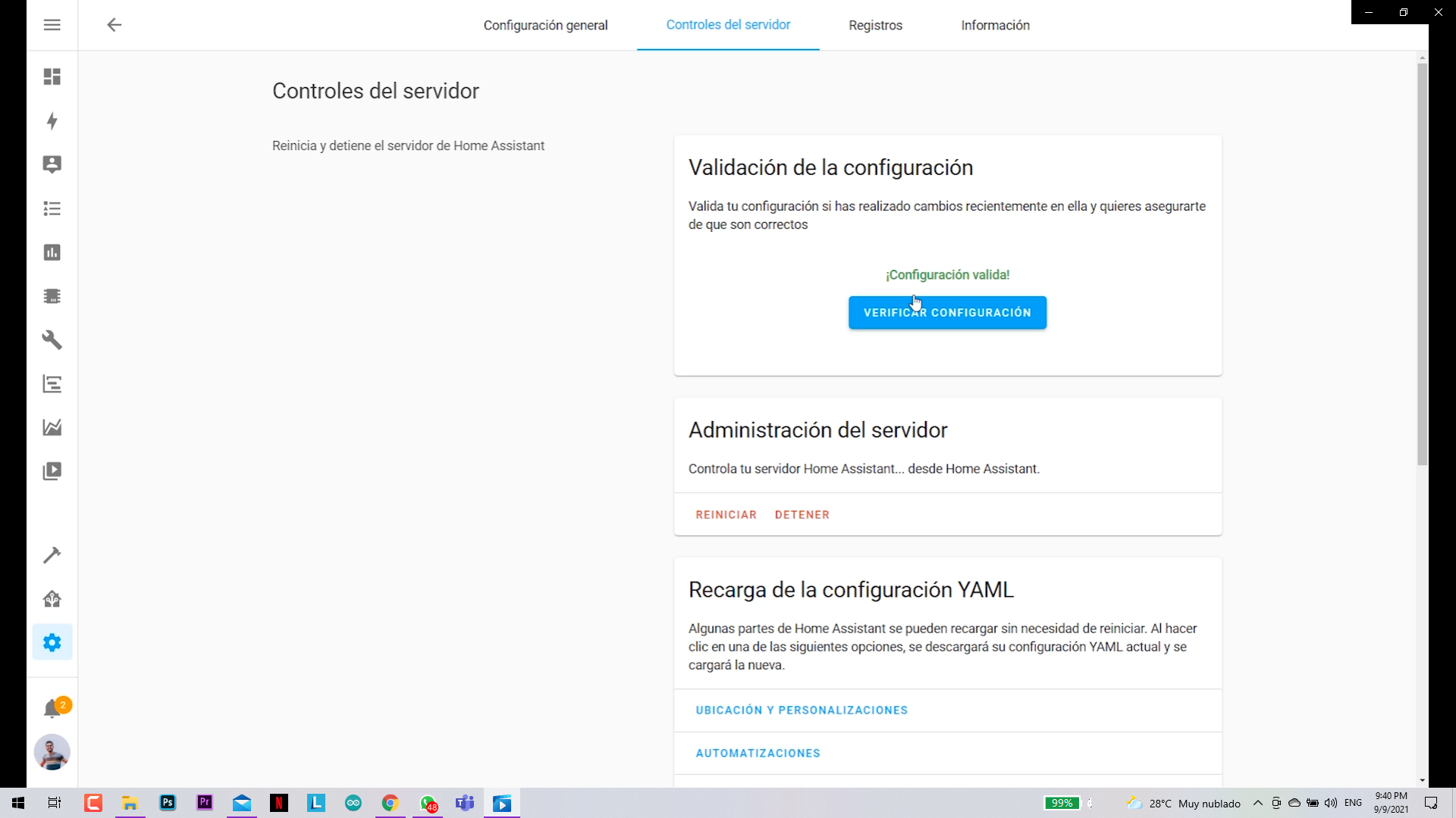
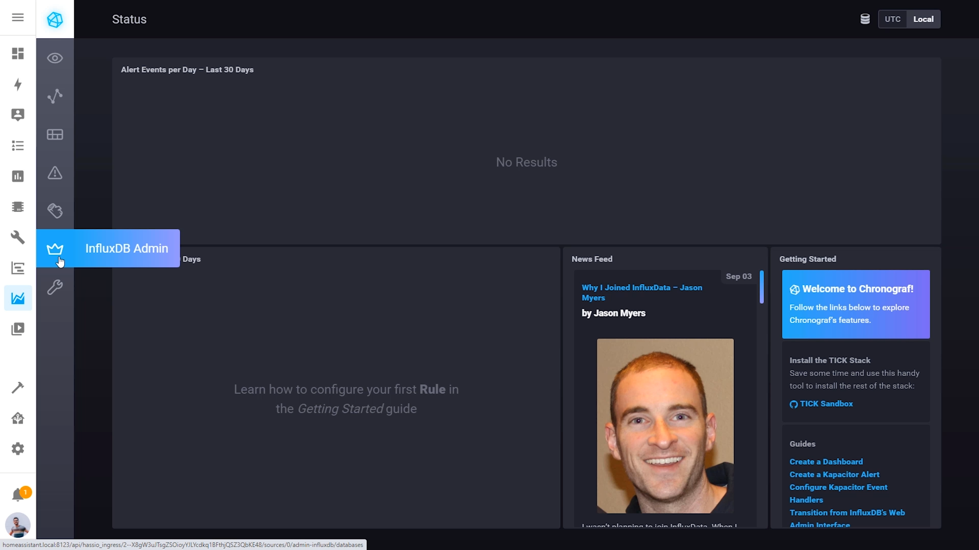
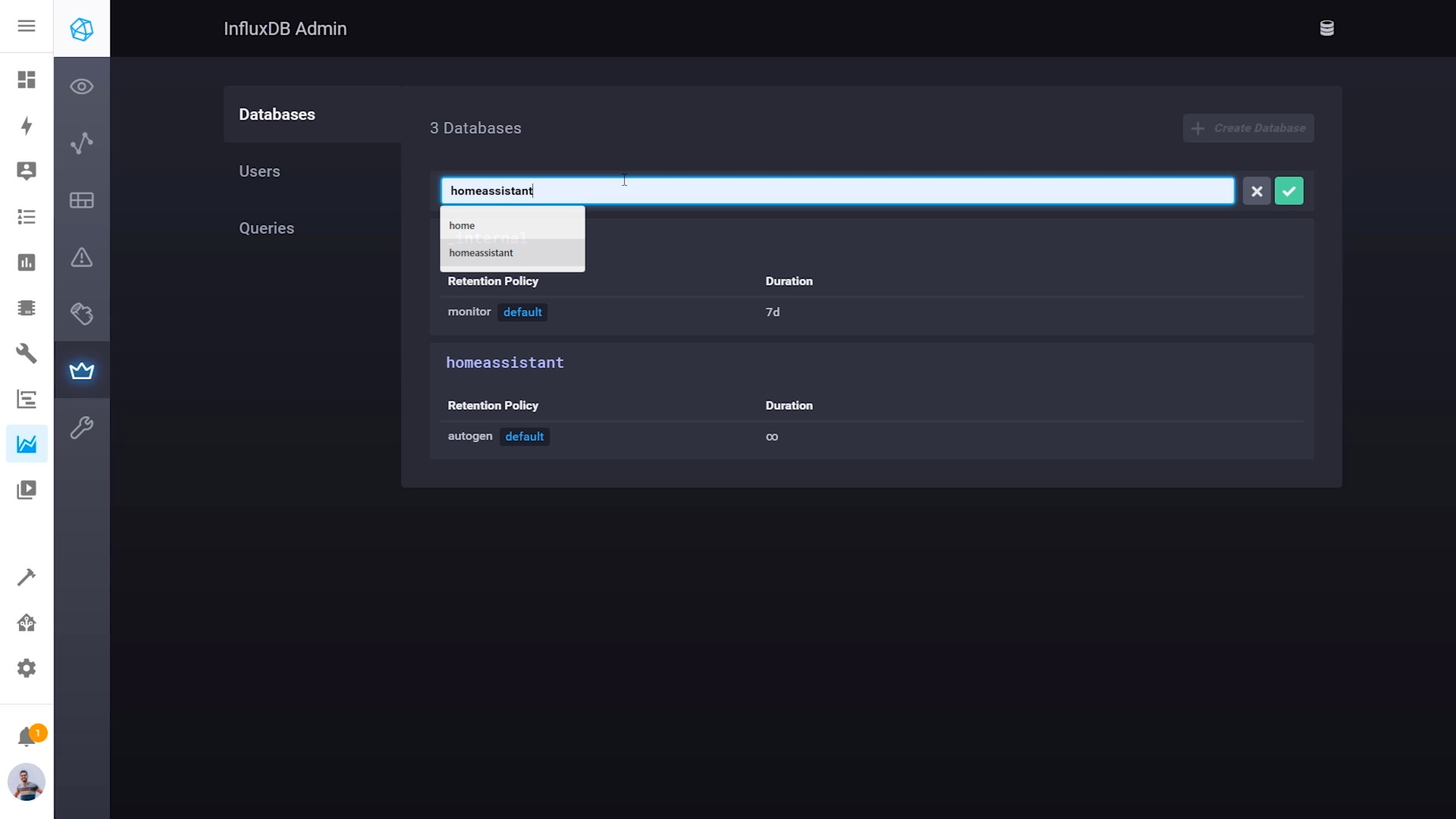
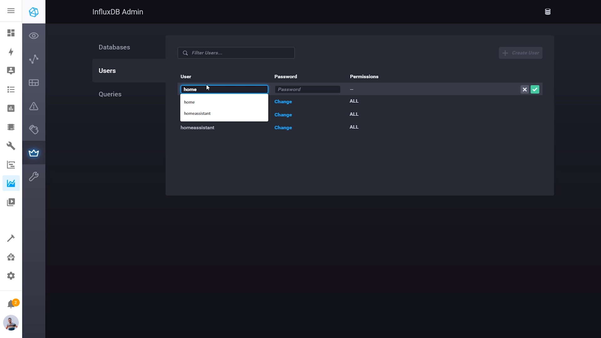
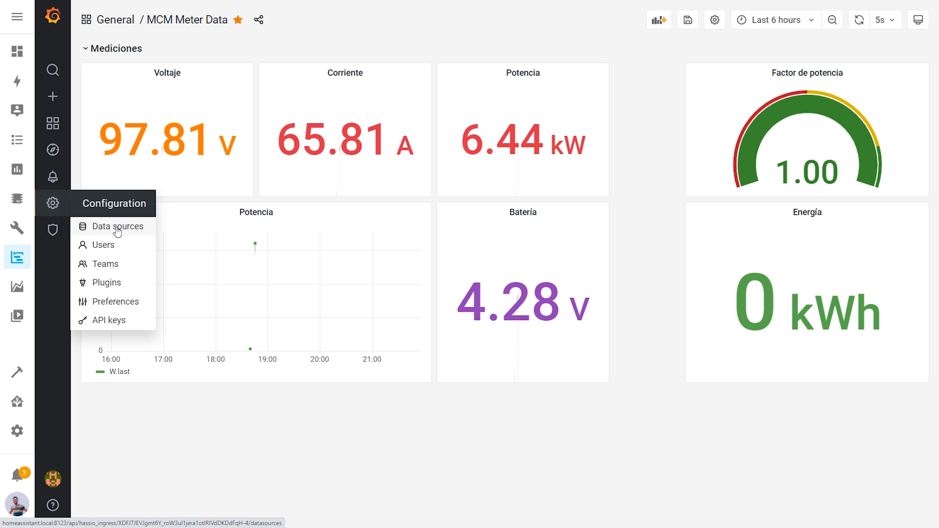
To make everything works, follow these steps in your Home Assistant system:
- Open your home assistant by searching it in your browser.
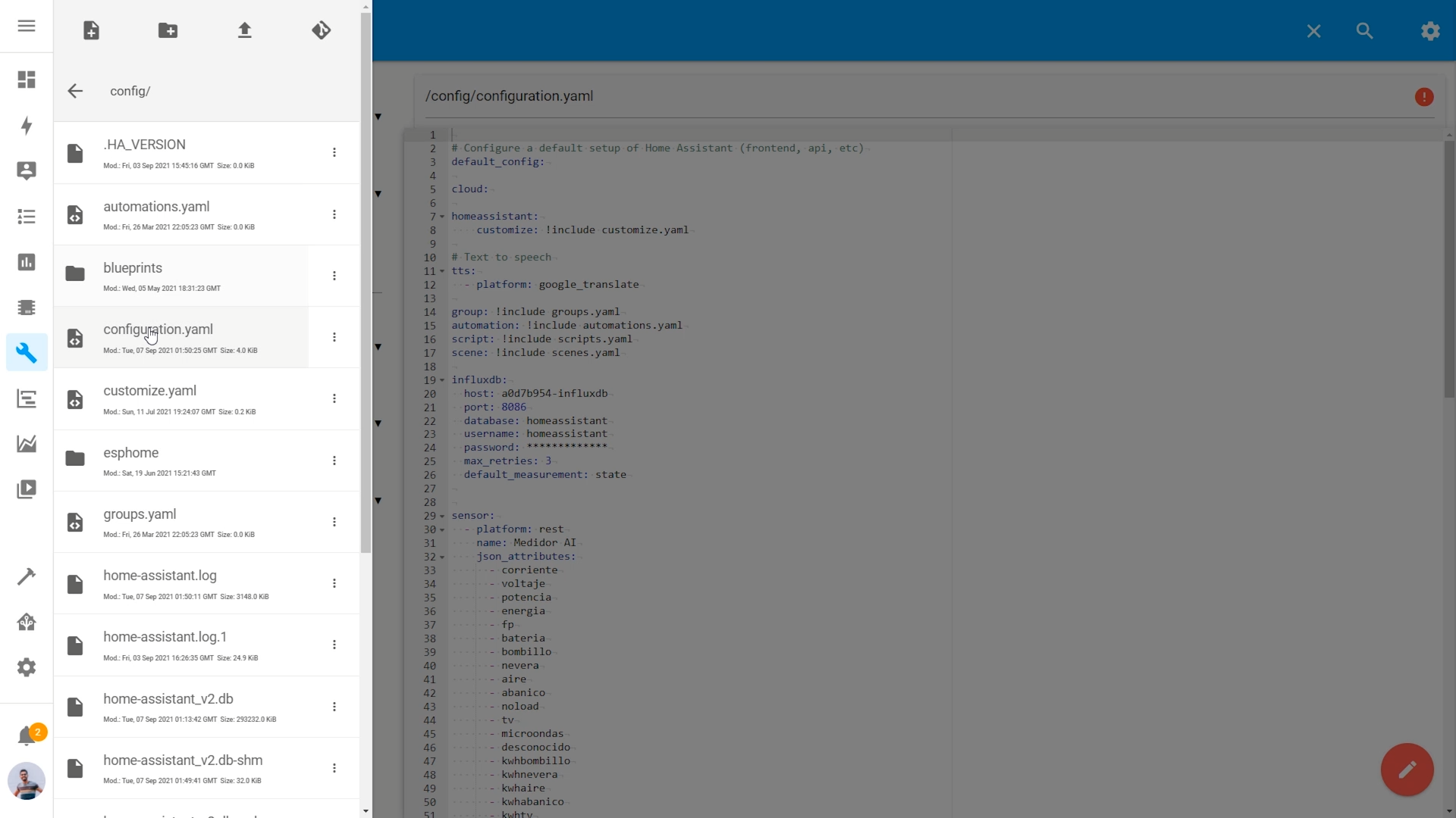
- Go to Supervisor> Adds on and install InfluxDB, Grafana and File Editor.
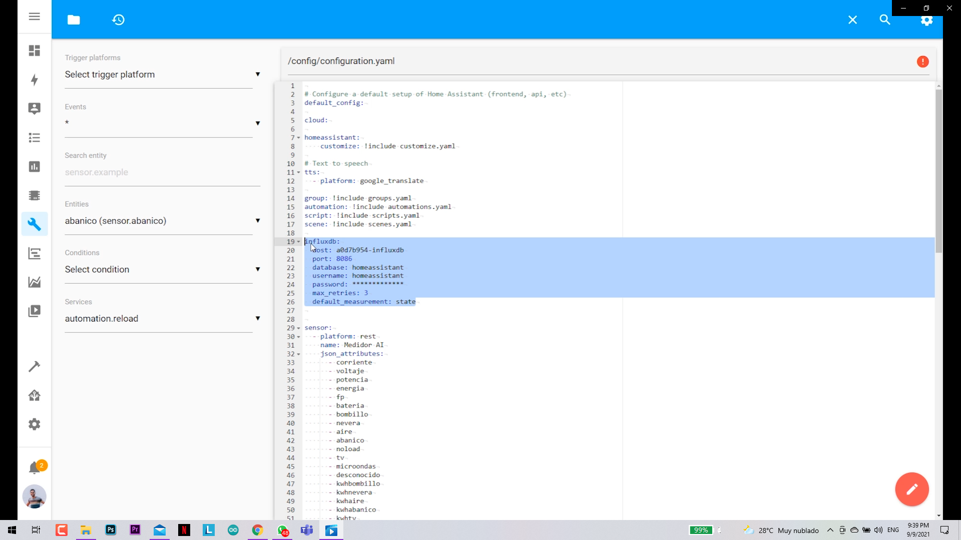
- Open the File Editor and search for the *Configuration.yaml* file
- Paste the configurations you found in the Github repository
- Reset your server after validating the configuration.
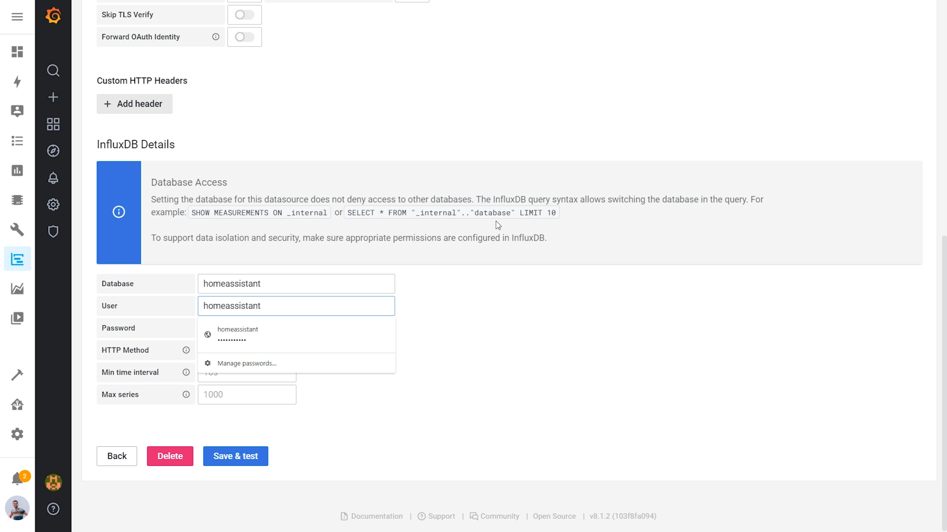
- Open InfluxDB> InfluxDB Admin (the crown)
- Create a database called "homeassistant"
- Create a user called "homeassistant" and add the same password you wrote in the "configuration.yaml"
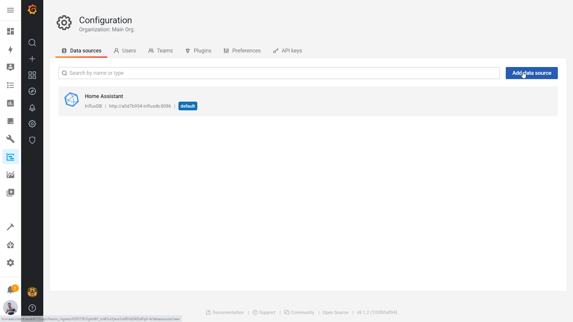
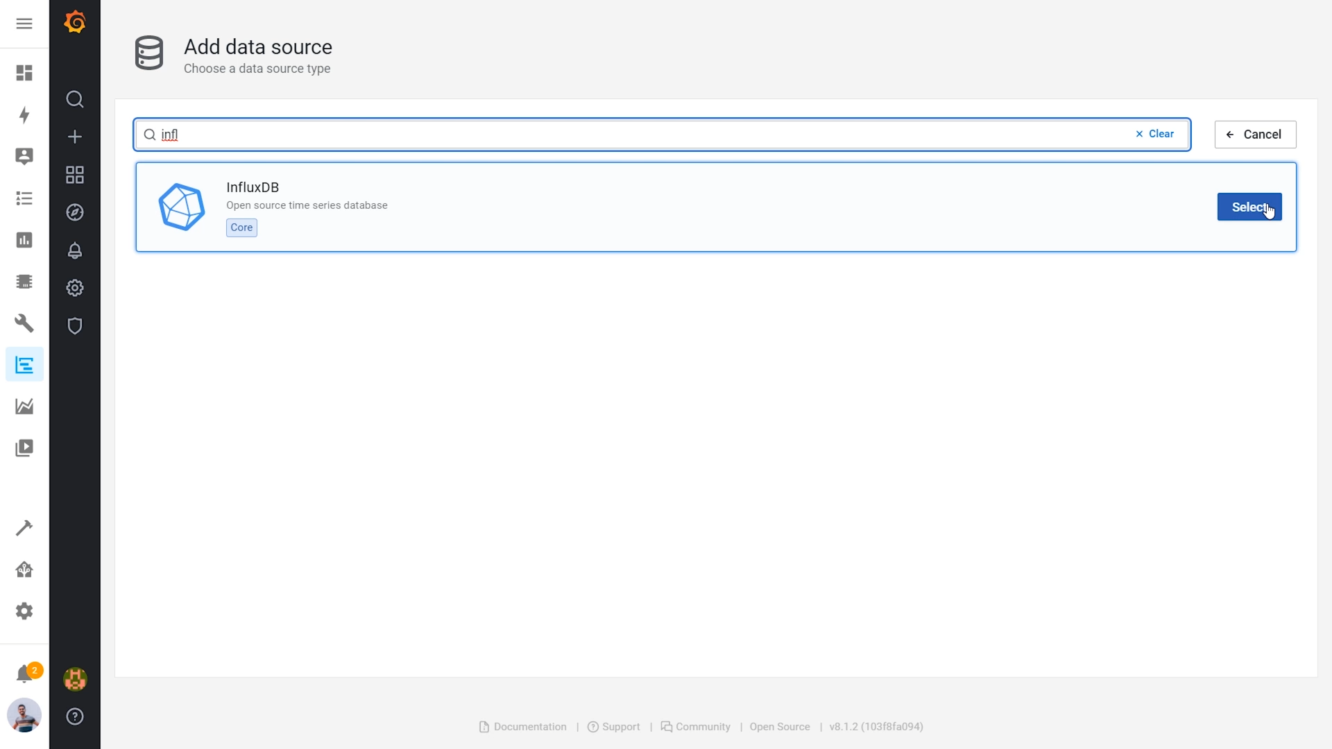
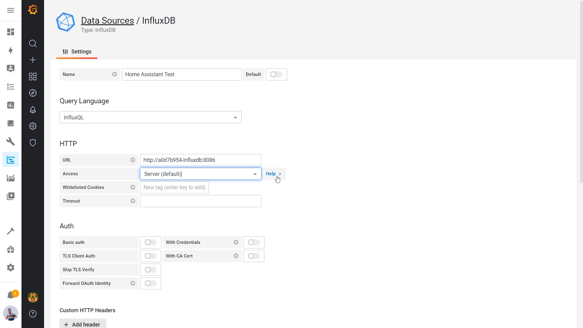
- Open Grafana > Configuration > Data sources > Add data source
- Search for InfluxDB and select it
- Modify this things:
- URL: http://a0d7b954-influxdb:8086
- Database: homeassistant
- User: homeassistant
- Password: the same as in the configuration.yaml
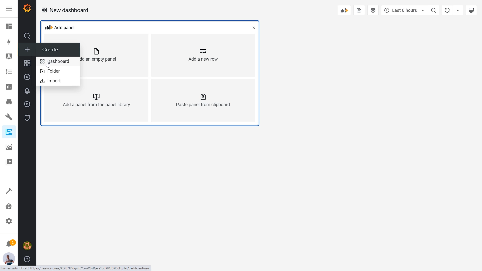
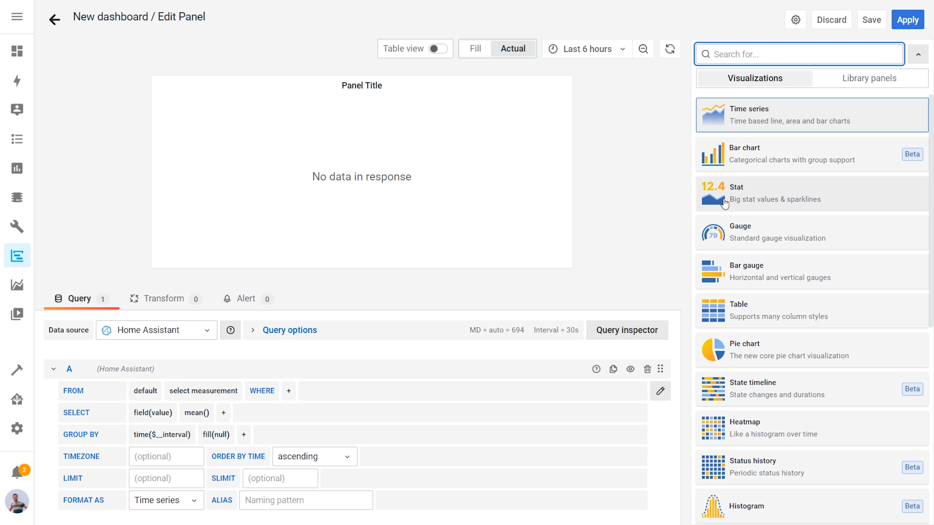
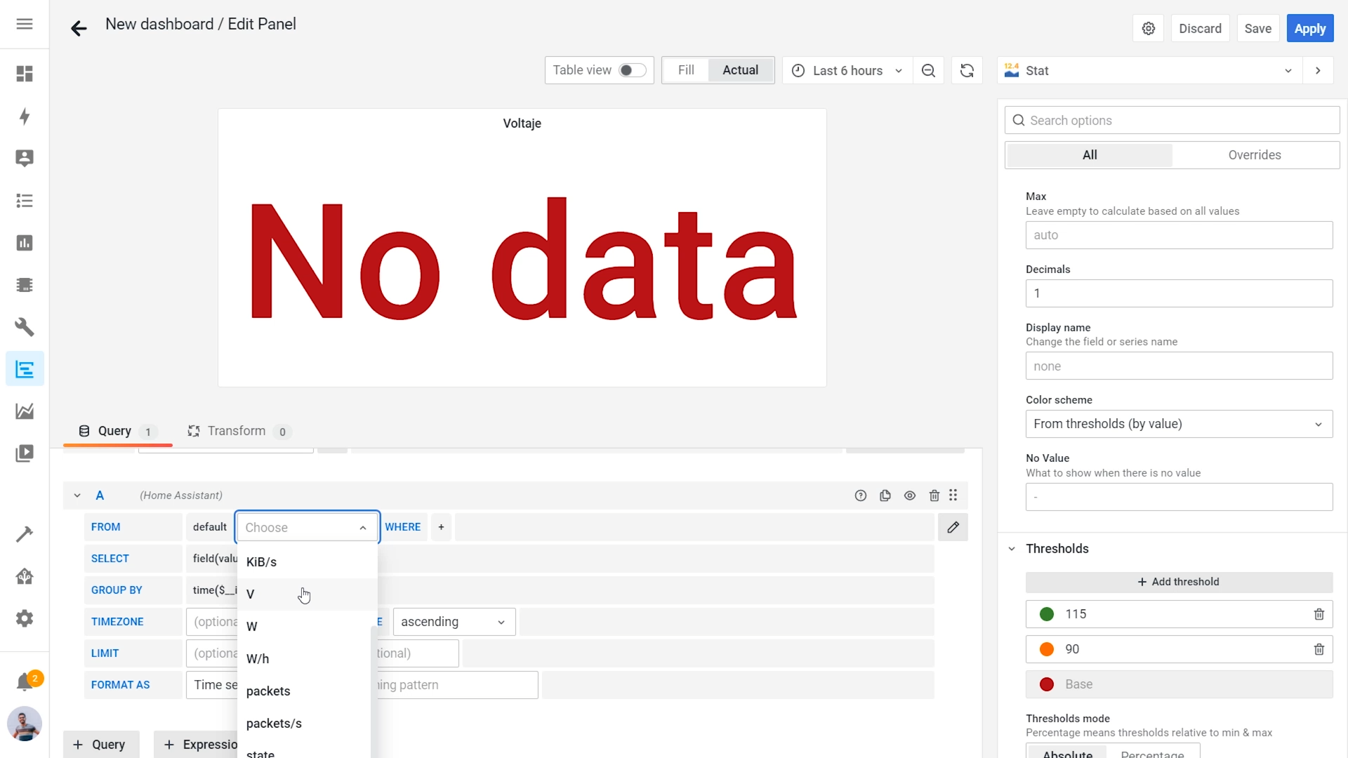
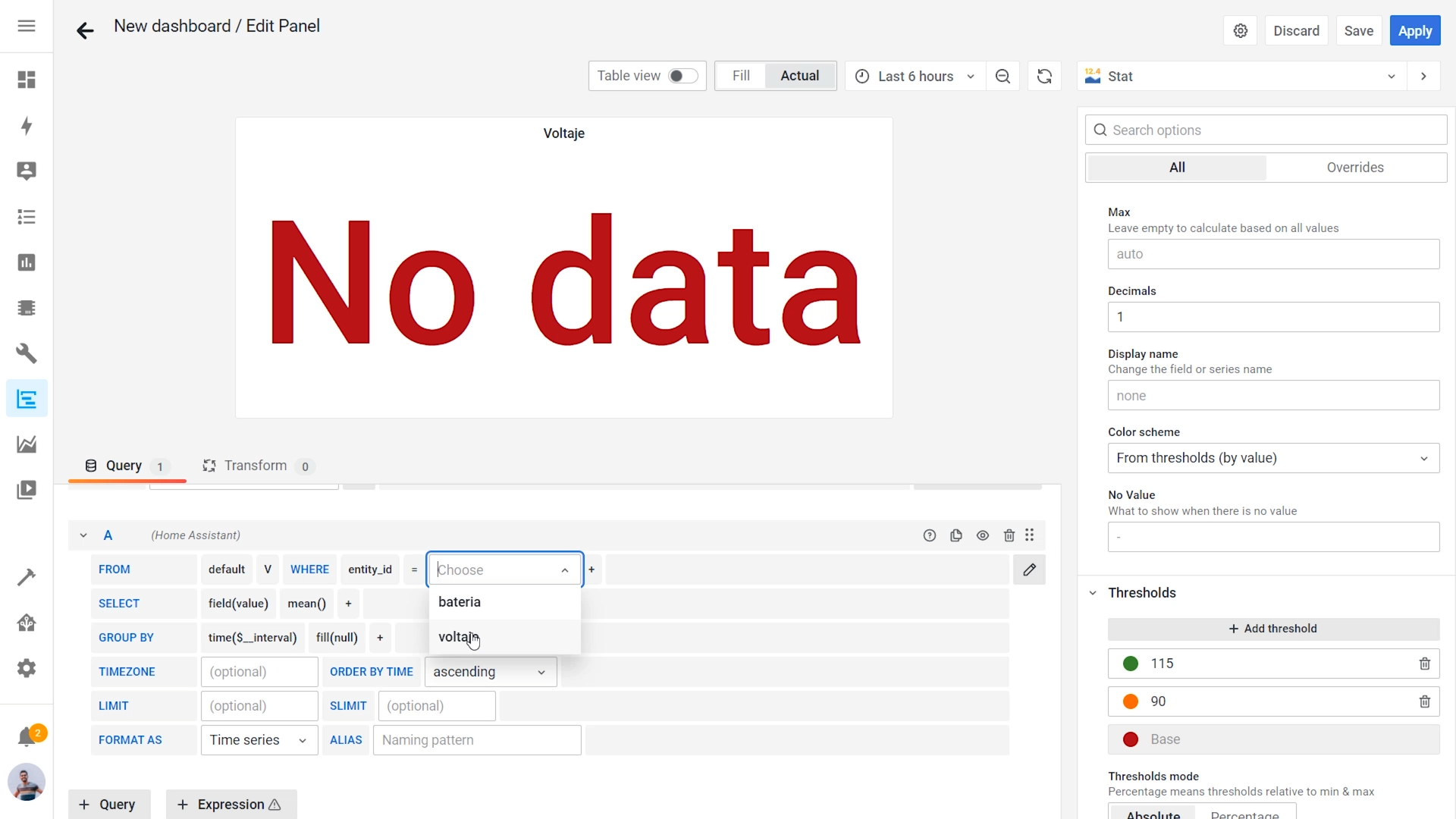
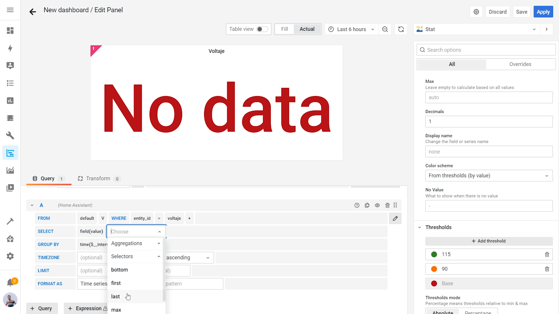
12. Go to + symbol and create a new dashboard
- Select the type of graph.
- Select mesurement -> V
- Entity-ID -> voltaje
- Select -> last()
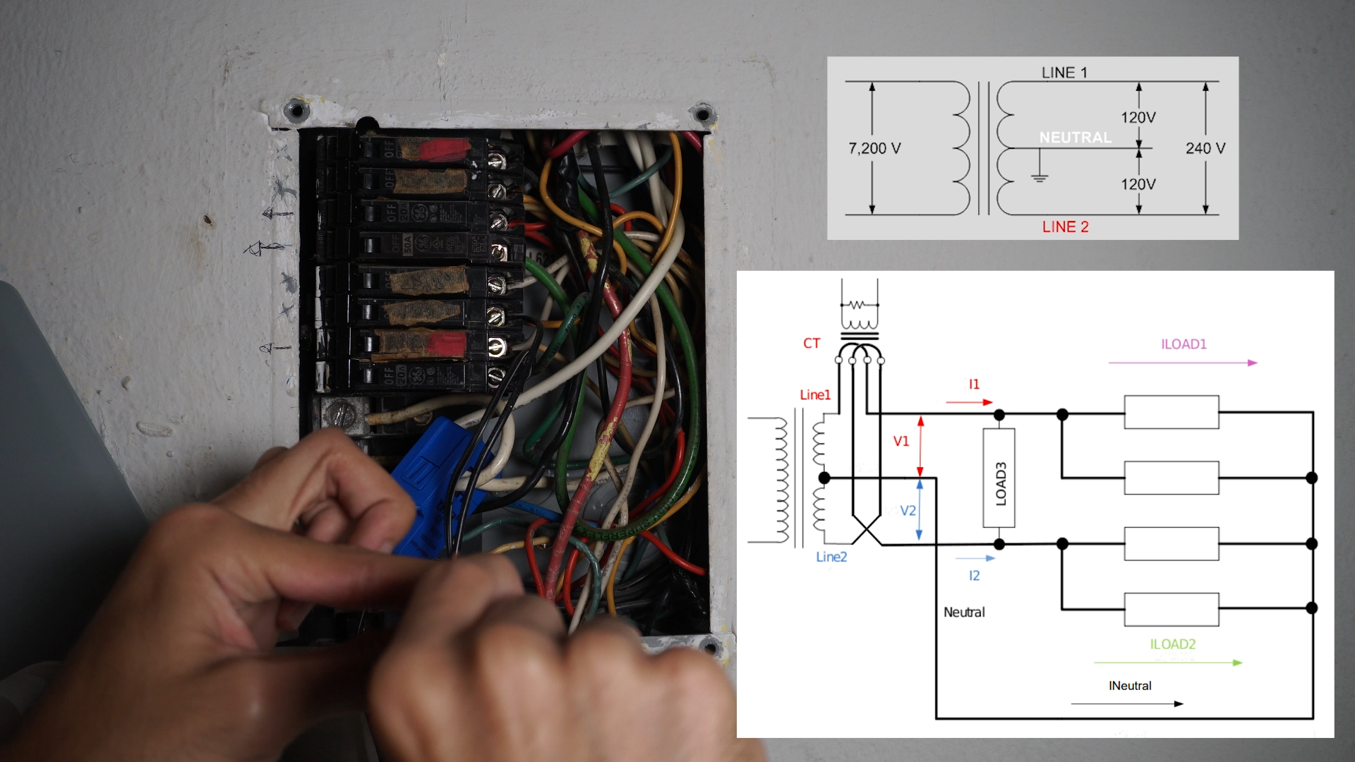
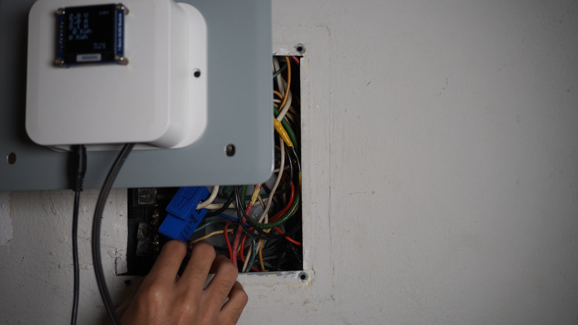
Fix the System to Your Electric Box
.png)
.png)
.png)
.png)
- Round your two main lines with the (current sensor) CT, one directly and other inversed as the diagram shown.
- Power the system connecting the AC cables to 120v, line and neutral of your electric box.
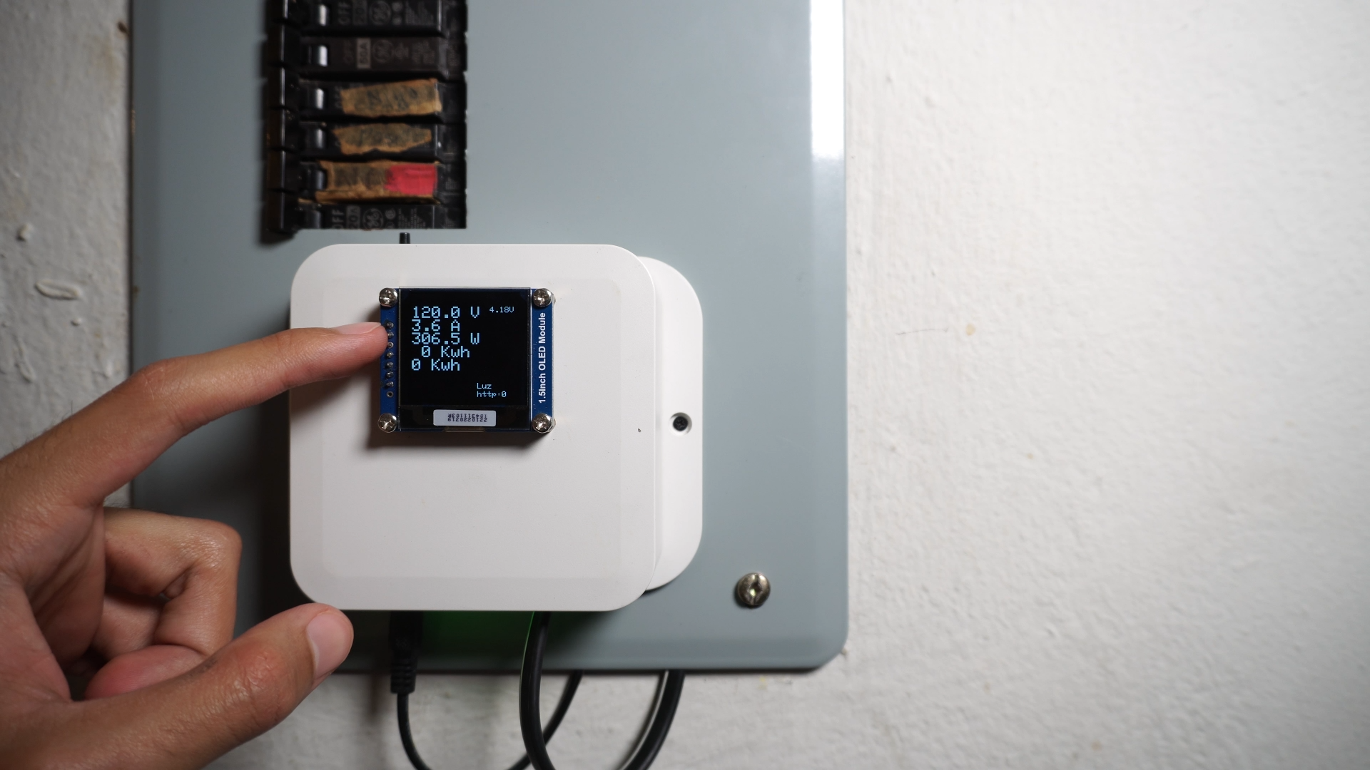
System Final Configuration
.png)
.png)
.png)
.png)
.png)
.png)
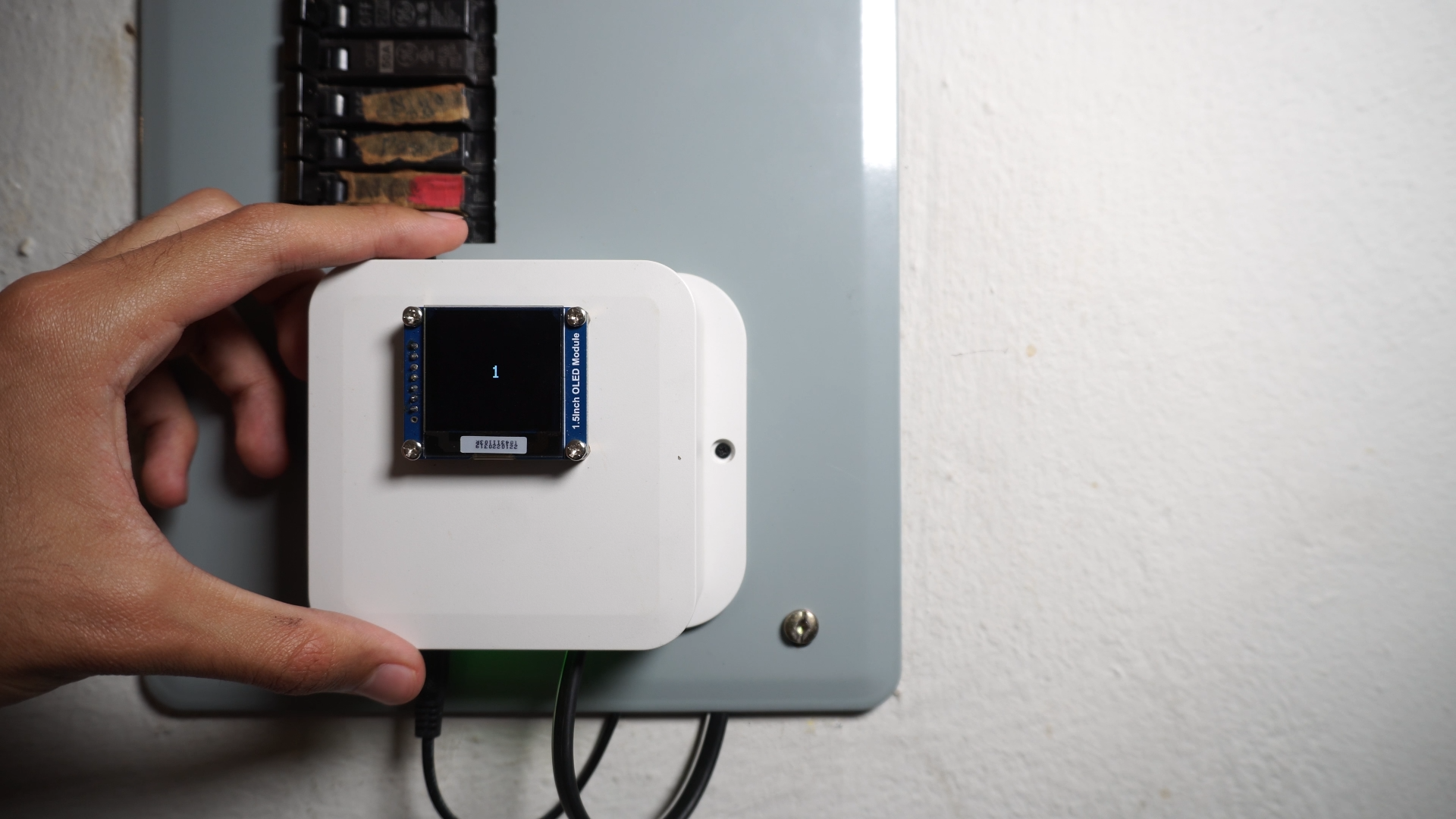
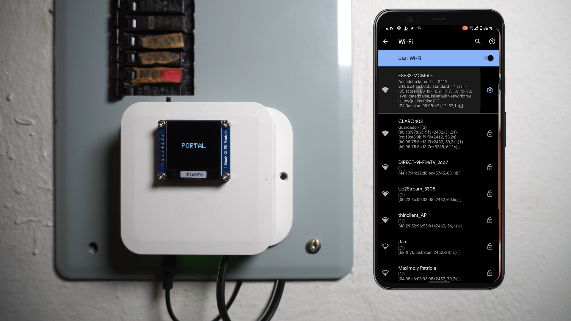
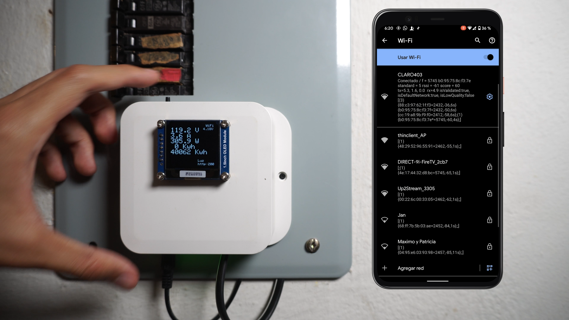
As you can see in the first picture, the system is up and working but not connected to the wifi yet, for that follow these steps:
- Press the config button for 1 second.
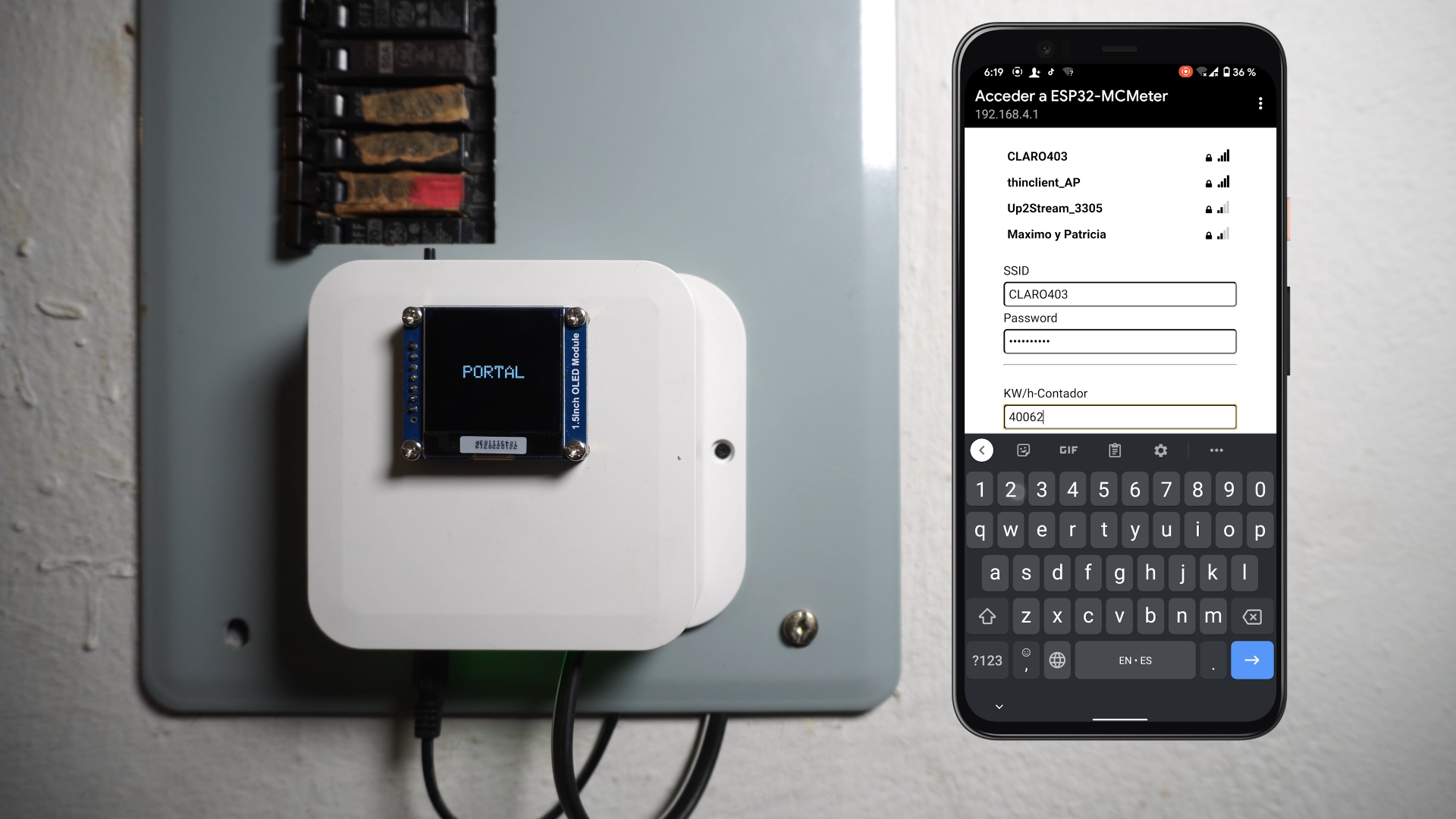
- A wifi network called ESP32-MCMeter will show up, select it in your phone.
- A portal will appear, click on config wifi and enter your wifi credentials and historic KWh usage.
- Click on save
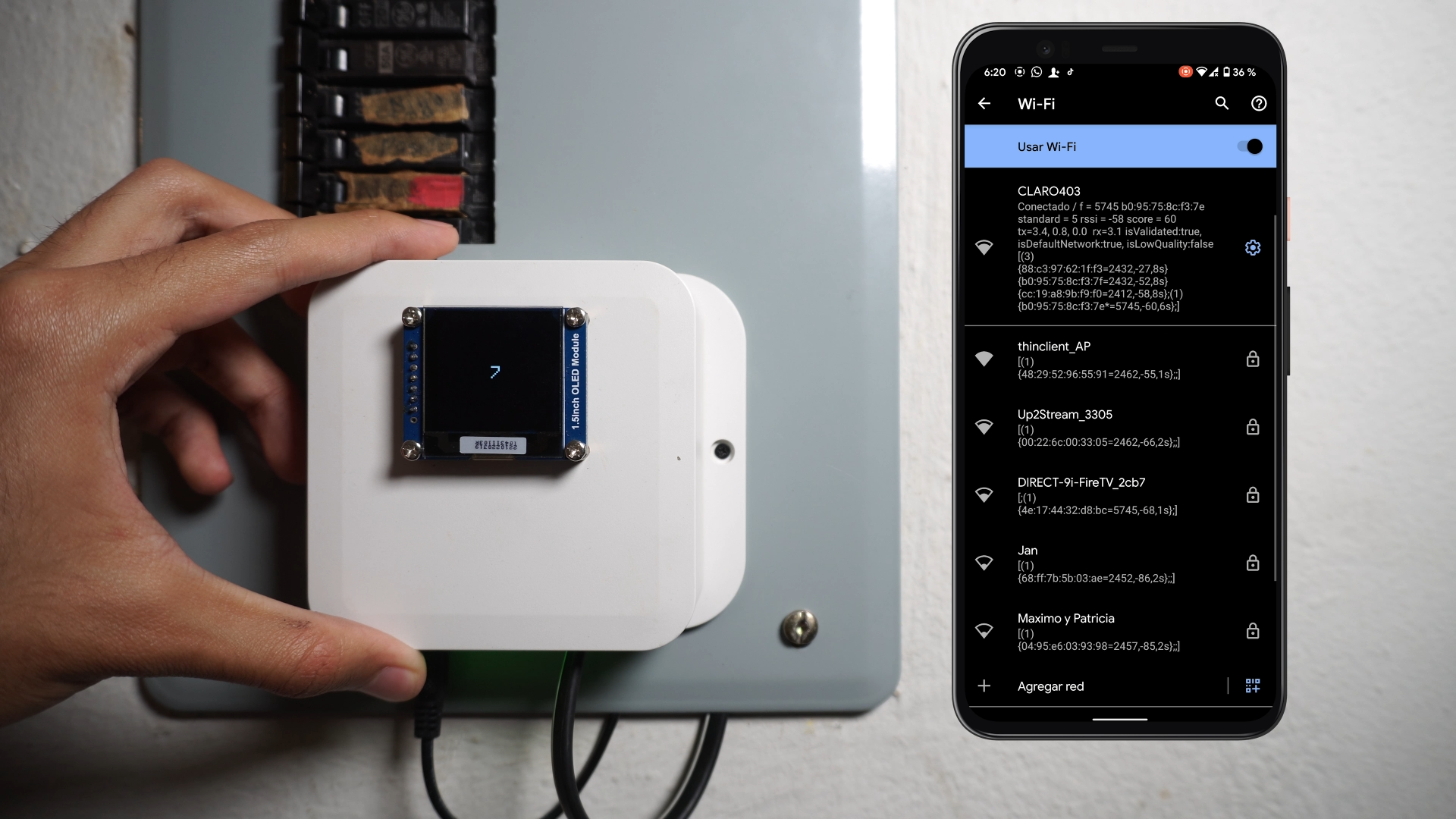
- Finally press the config for 7 seconds to reset the system.
- Now it should be connected to your WiFi and sending data to the server in Home Assistant
Final Test and Enjoy
.png)
.png)
.png)
.png)
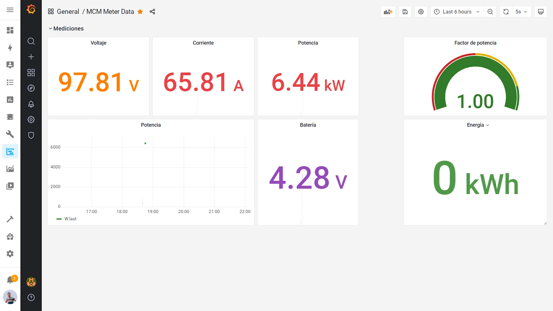
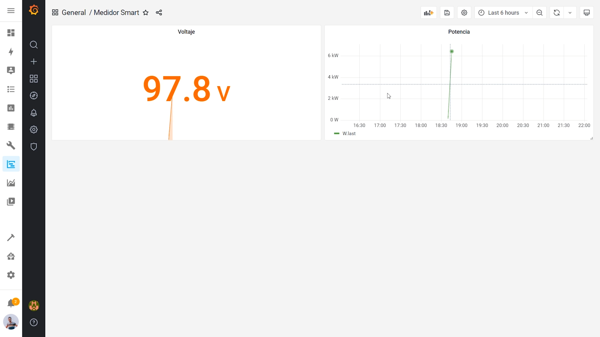
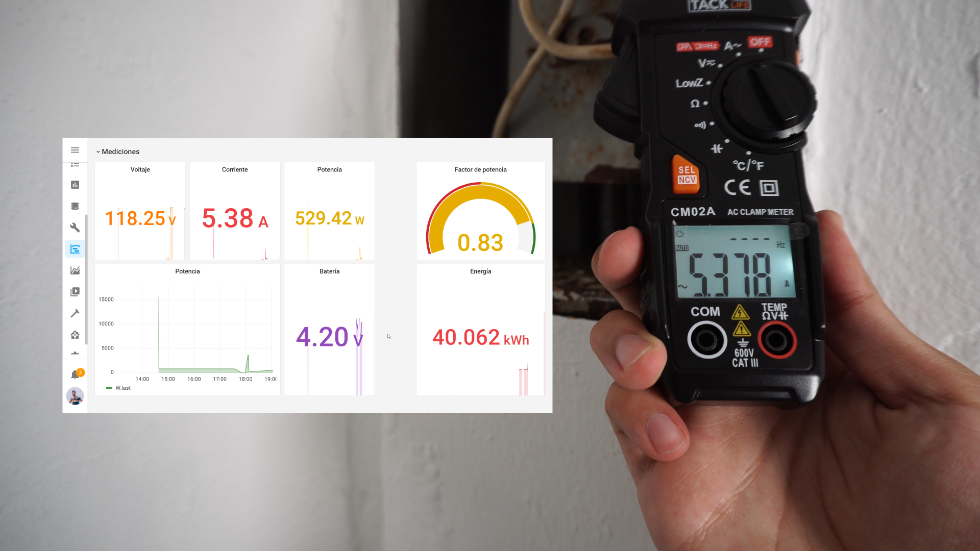
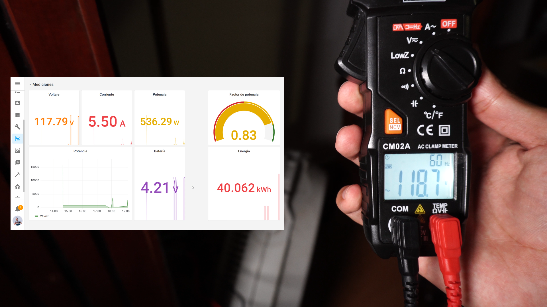
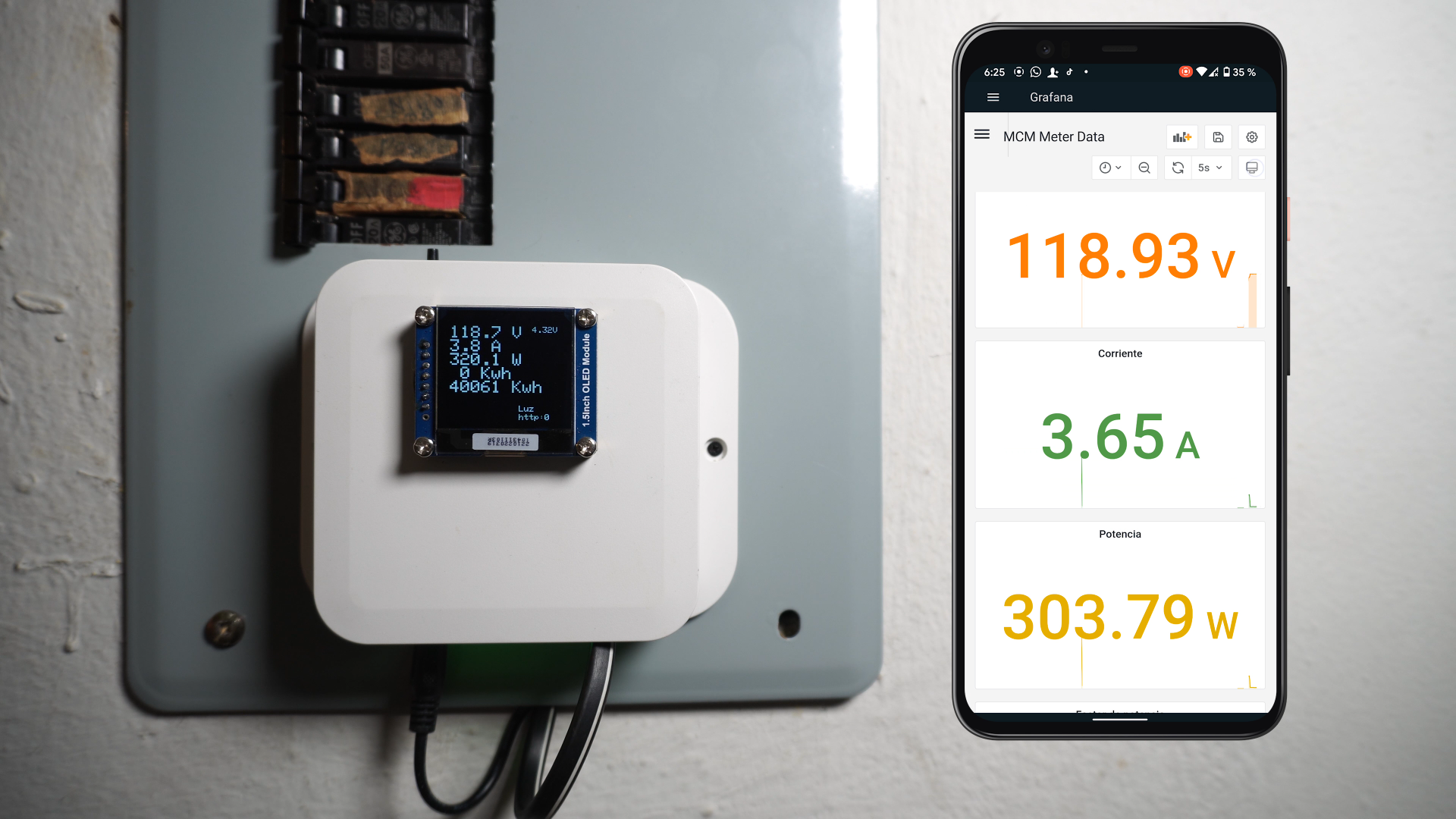
Now you will be able to see your power usage statistics in your Home Assistant dashboard.
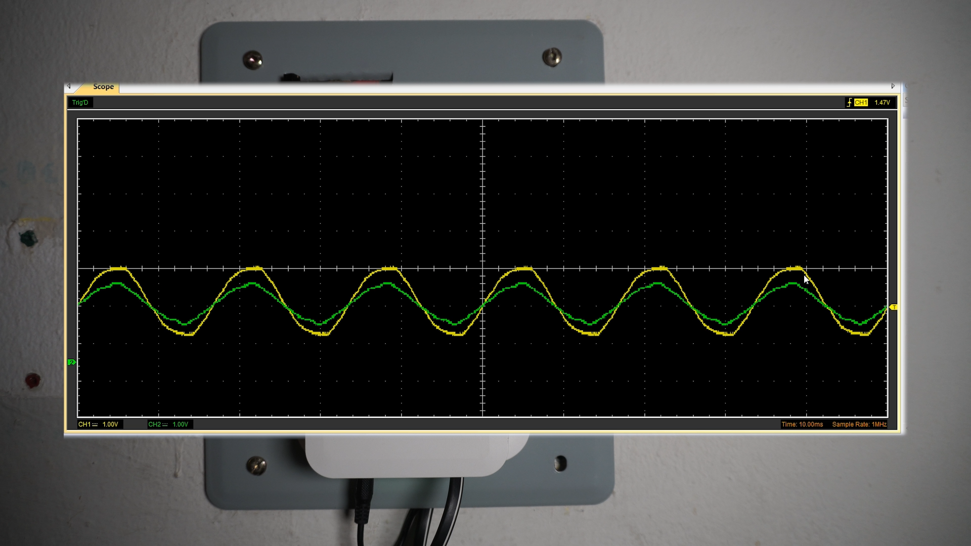
Here you can see that I compared the measured data with the data shown by the system and they almost match perfectly, so the system is precise enough.