Smart Alarm Clock
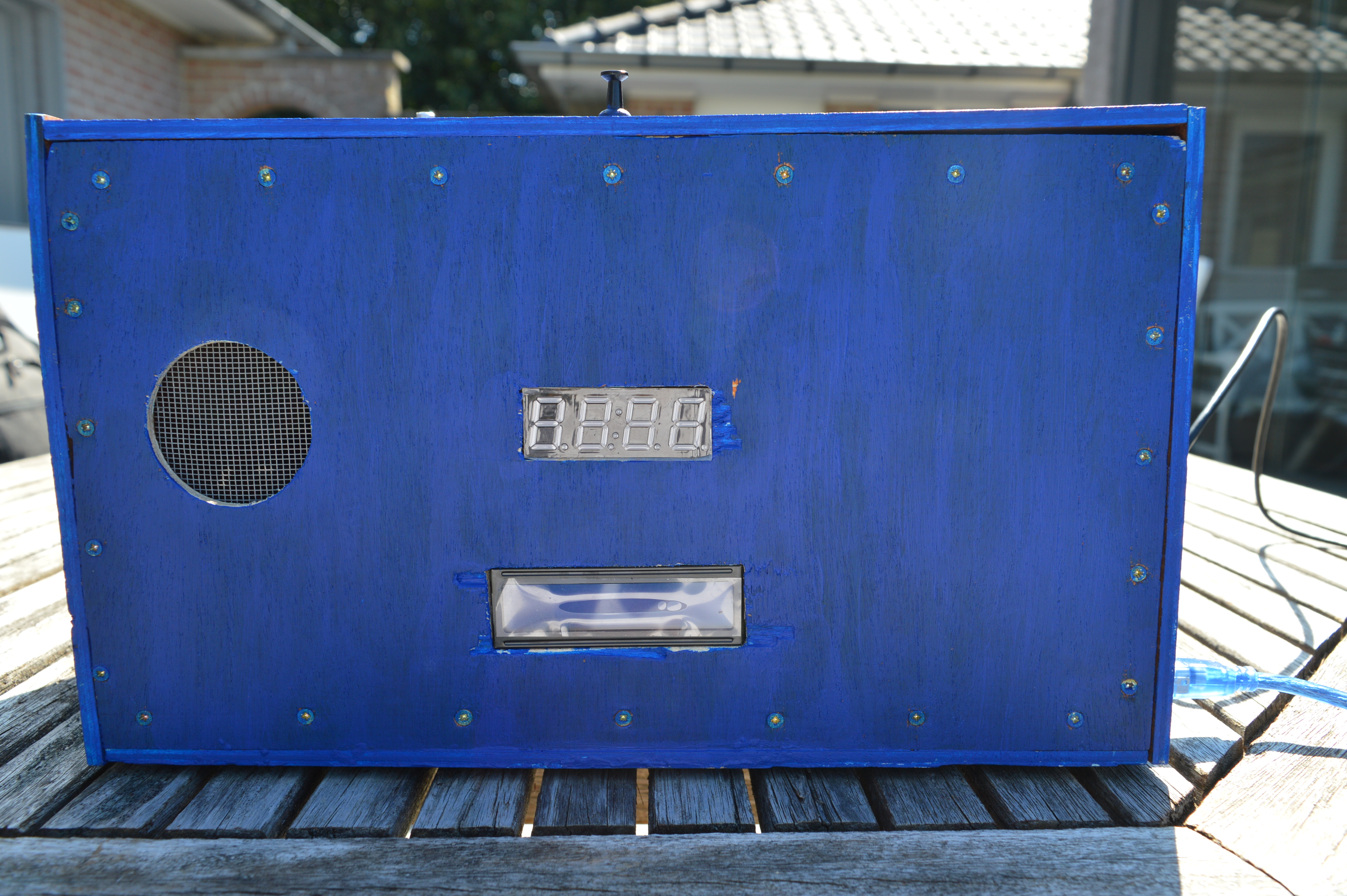
Hello, my name is Alexandra Christiaens and I study Media and communication Technology at Howest in Kortrijk, Belgium.
As a school assignment, we were required to make an IoT device. We were encouraged to make something that would make a difference in either our own lives or in the lives of people we know. I found it rather difficult to find a project and when I tried to search for a fitting project, I often thought: “I’m too tired for this.” So eventually I realized that this could be my project: I would make a smart alarm clock that would both help me get up in the morning and help me get to bed in time in the evening. Since the requirements for this assignment dictated that we should use a Raspberry Pi to run everything on, I decided to call my device “Sleepi” as a pun.
If you’d like to make this device yourself and get a decent sleeping routine like me, then check out this handy guide I wrote below. If you want to know more about me and other projects I made or will make, check out my portfolio.
Step1: Collecting the Components
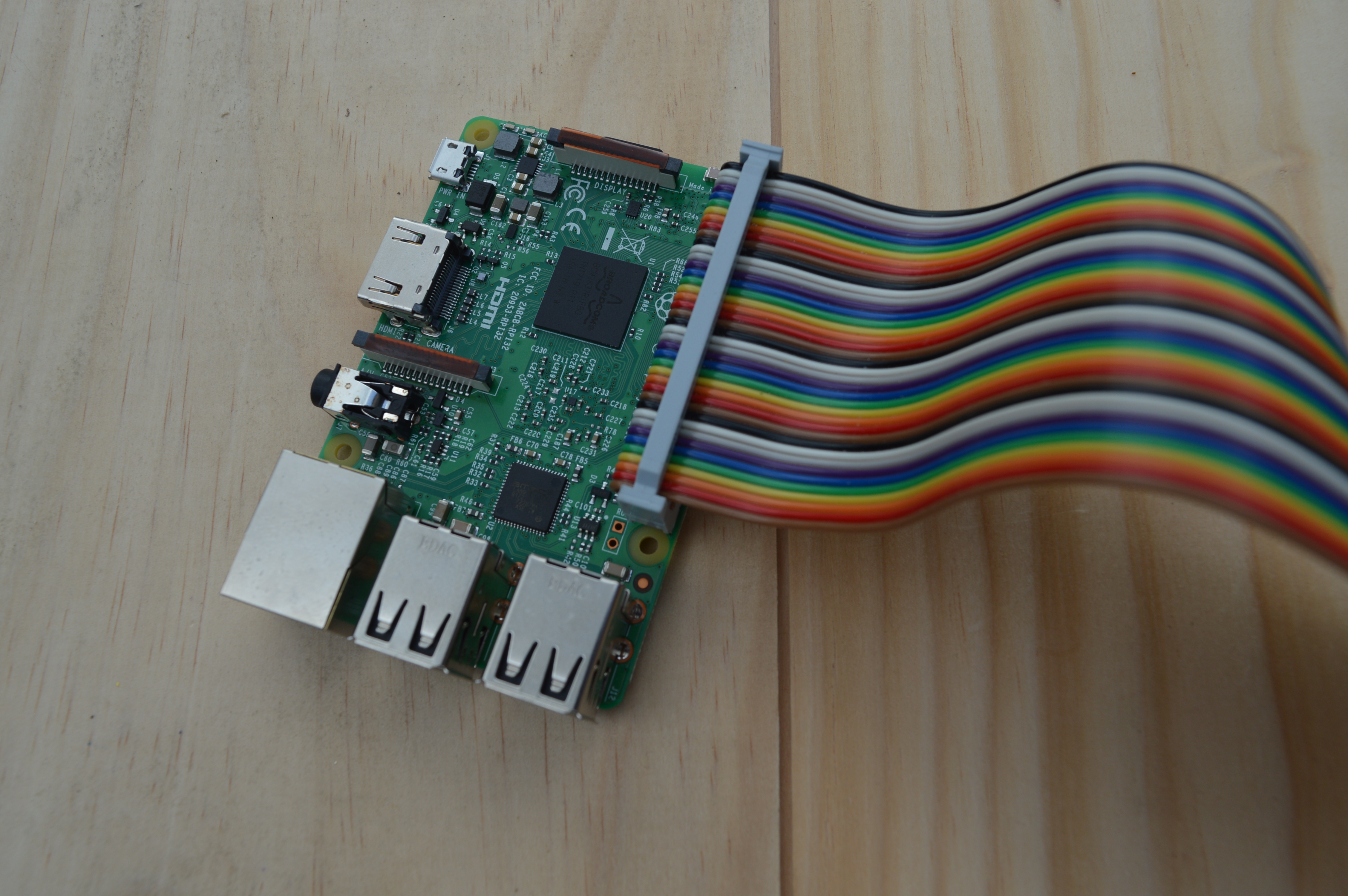
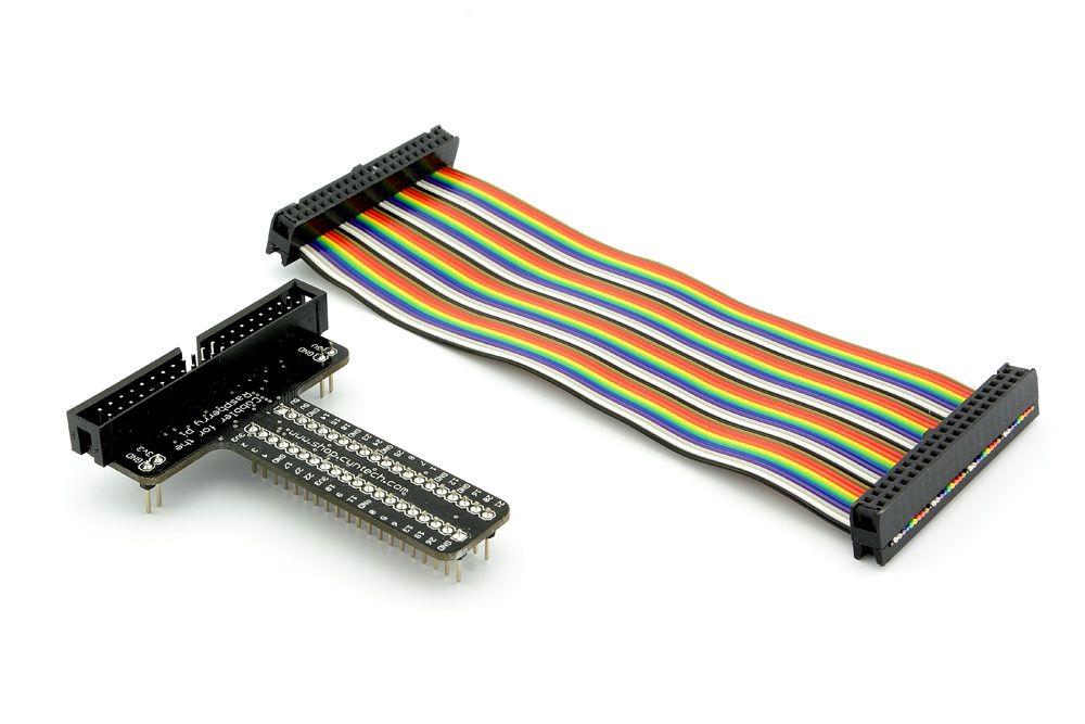
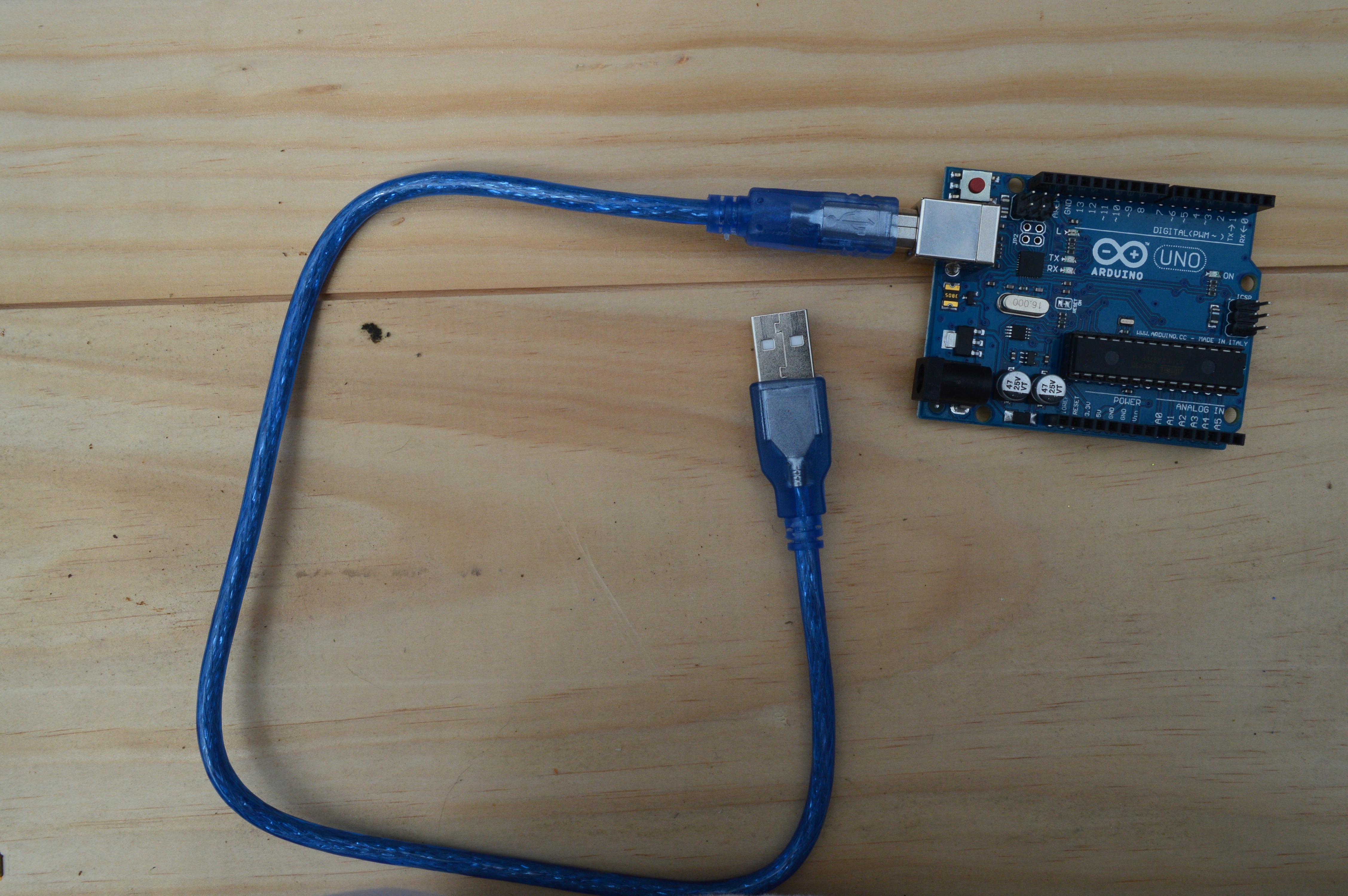
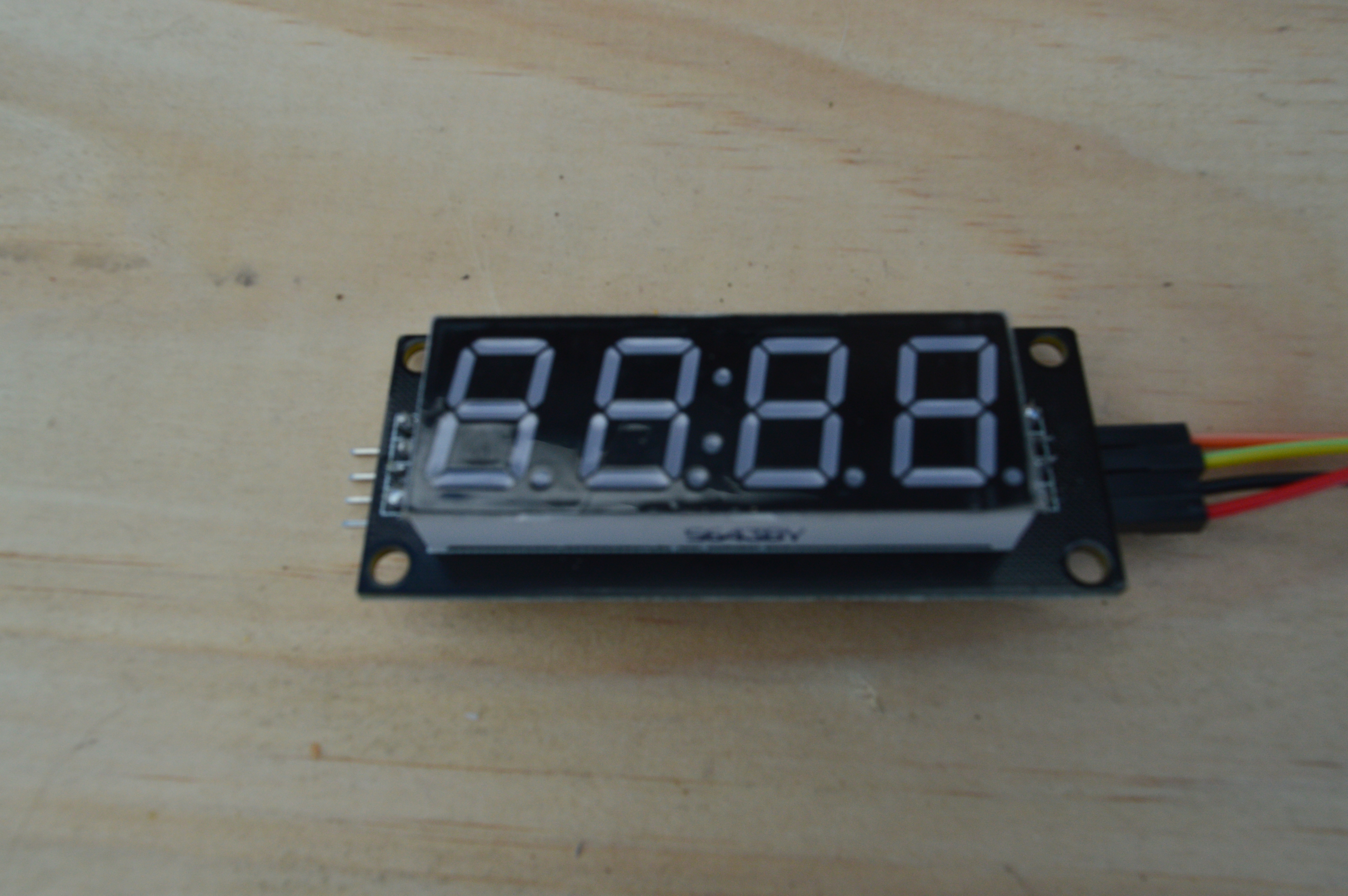
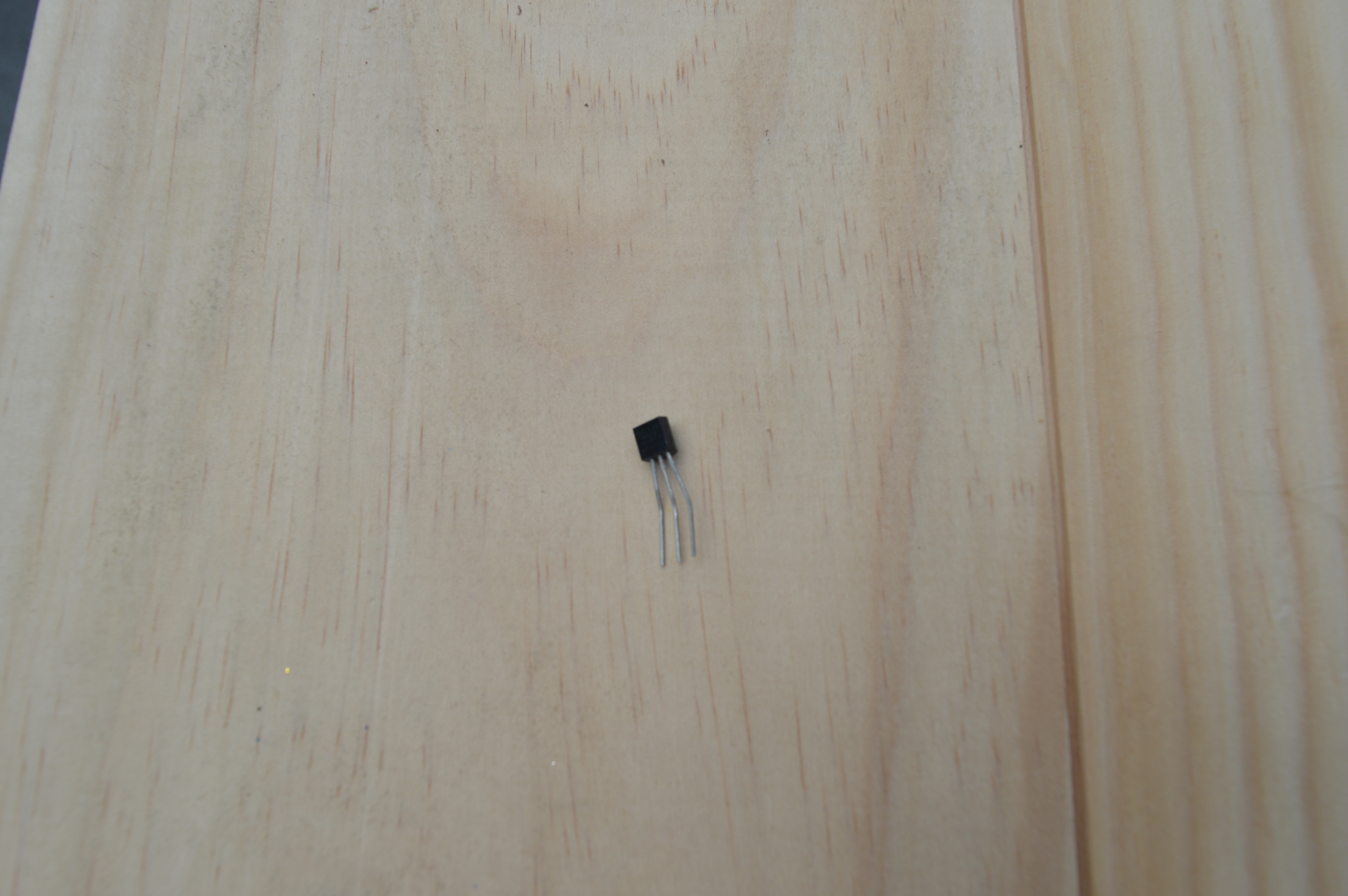
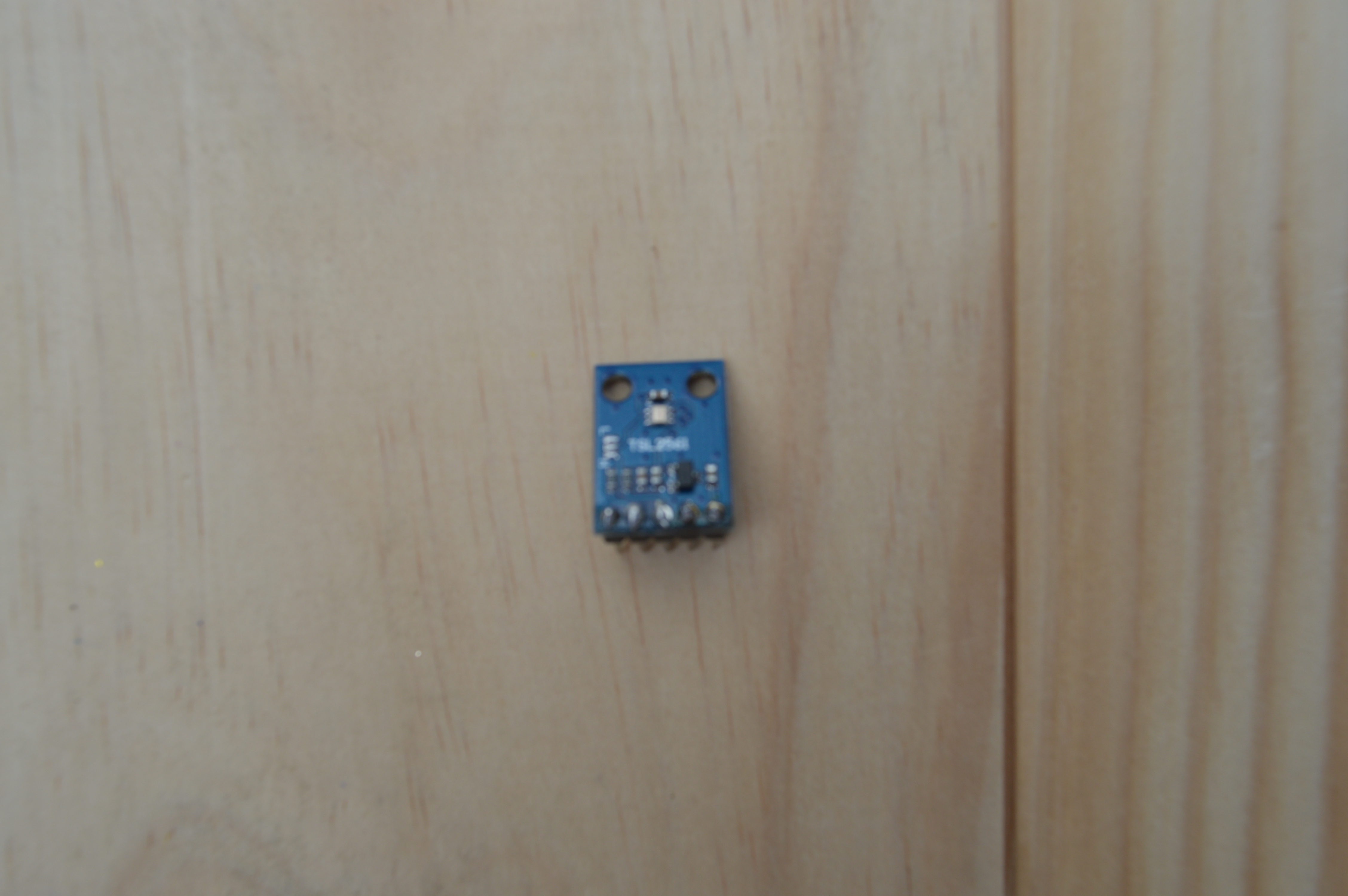
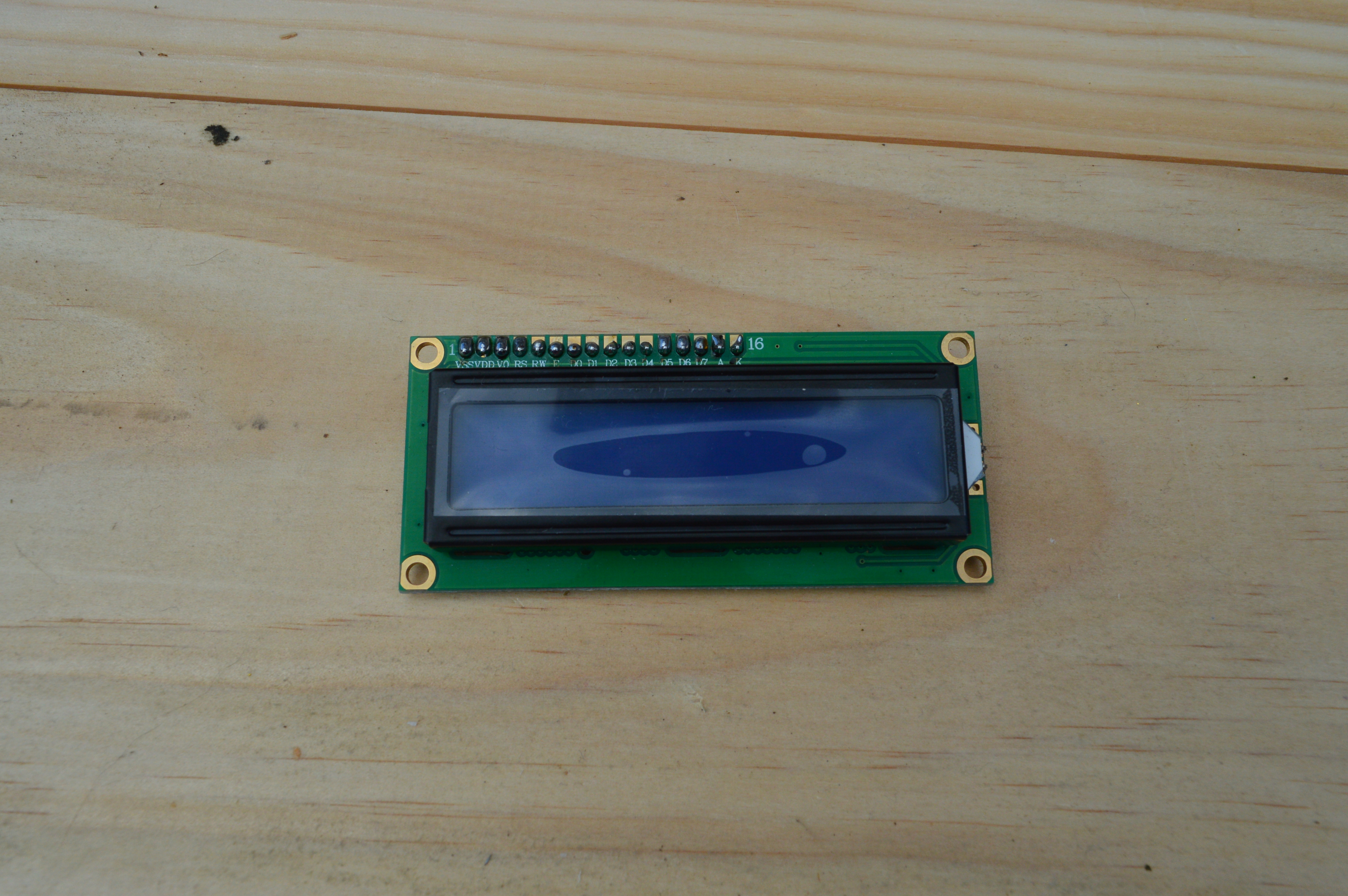
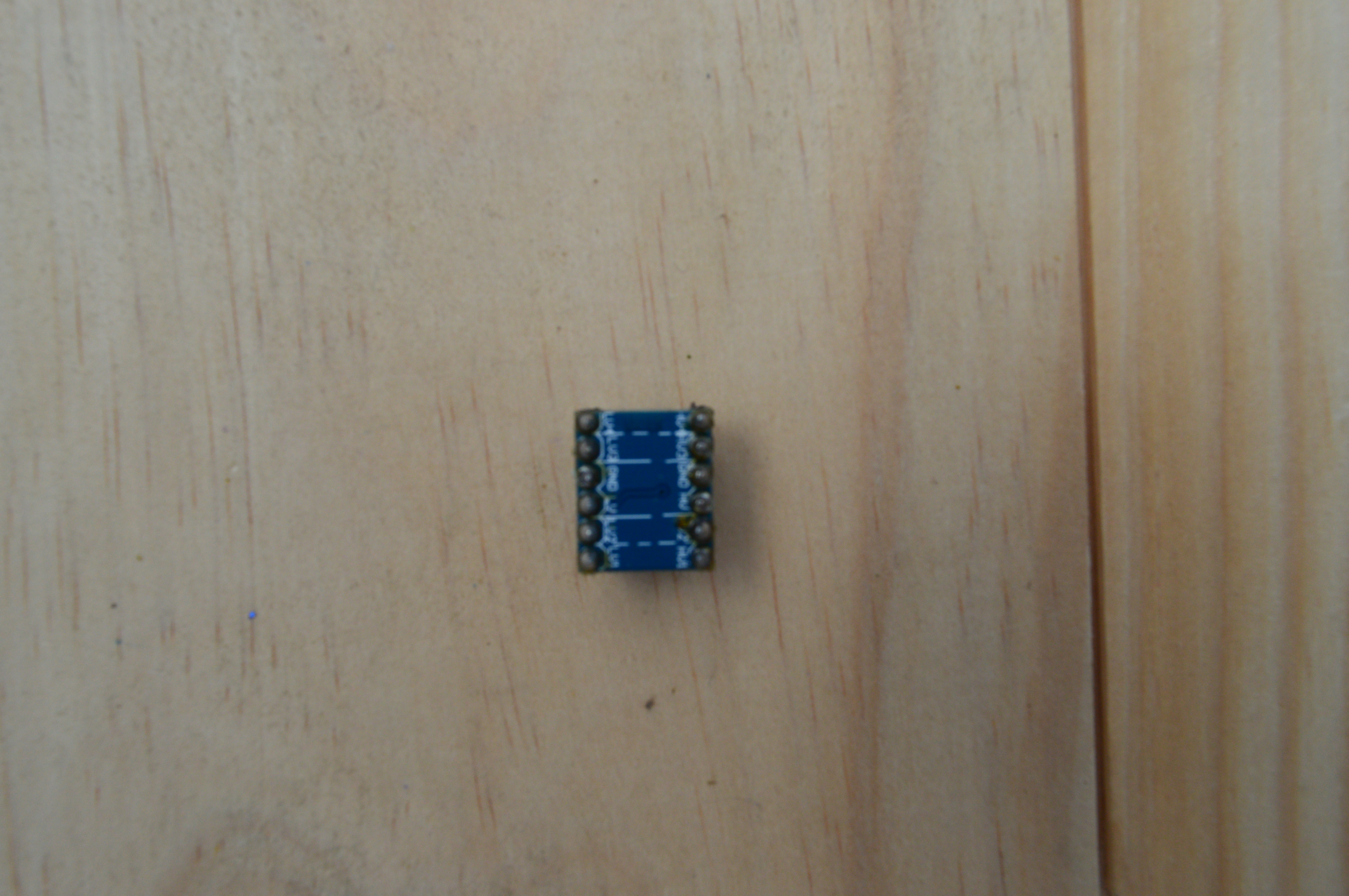
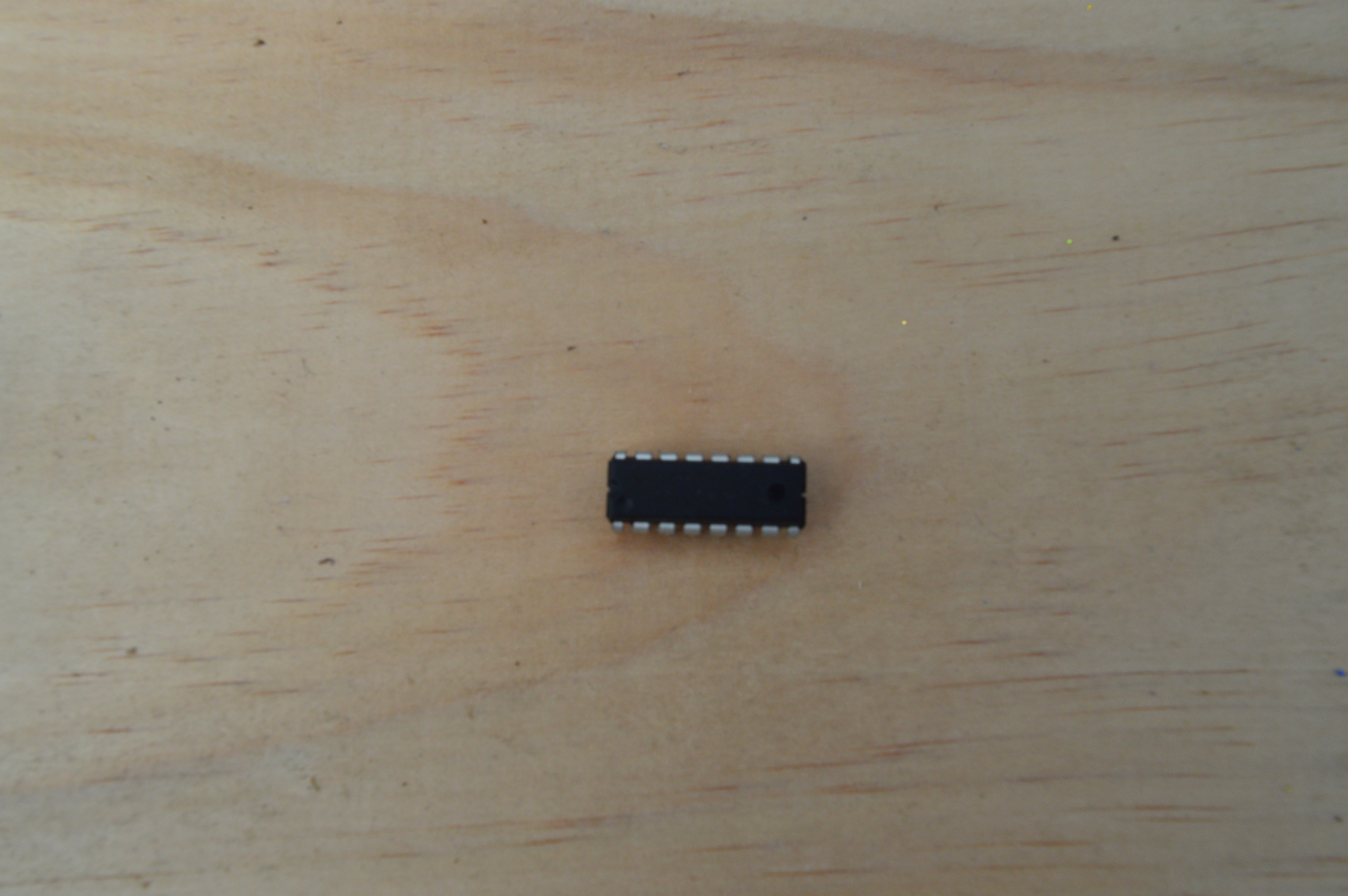
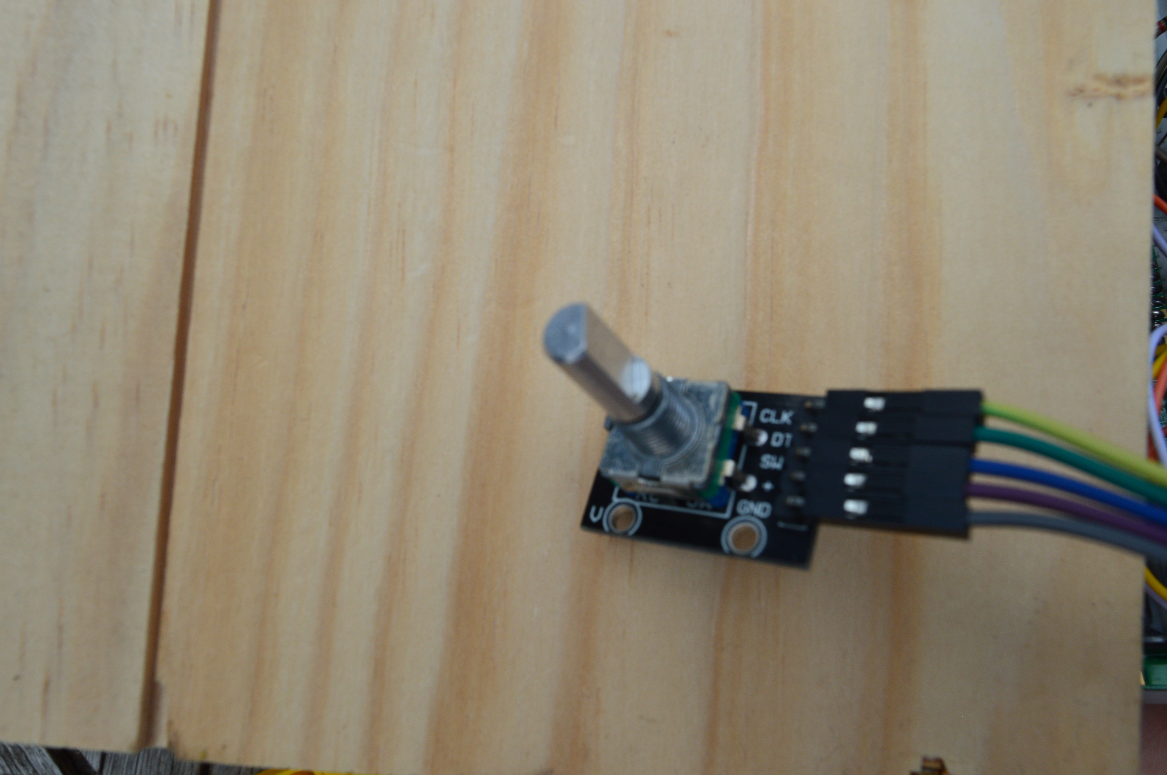
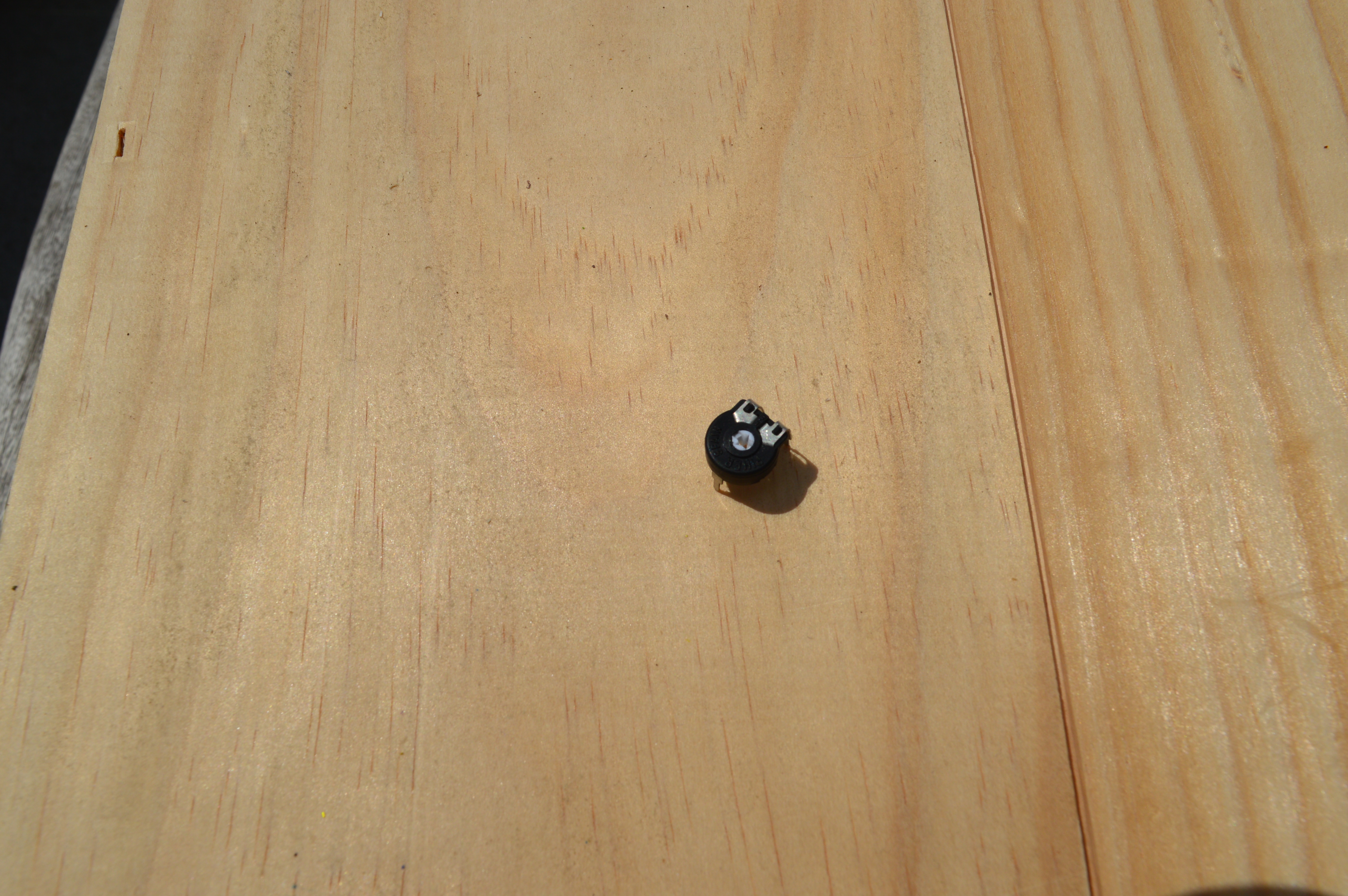

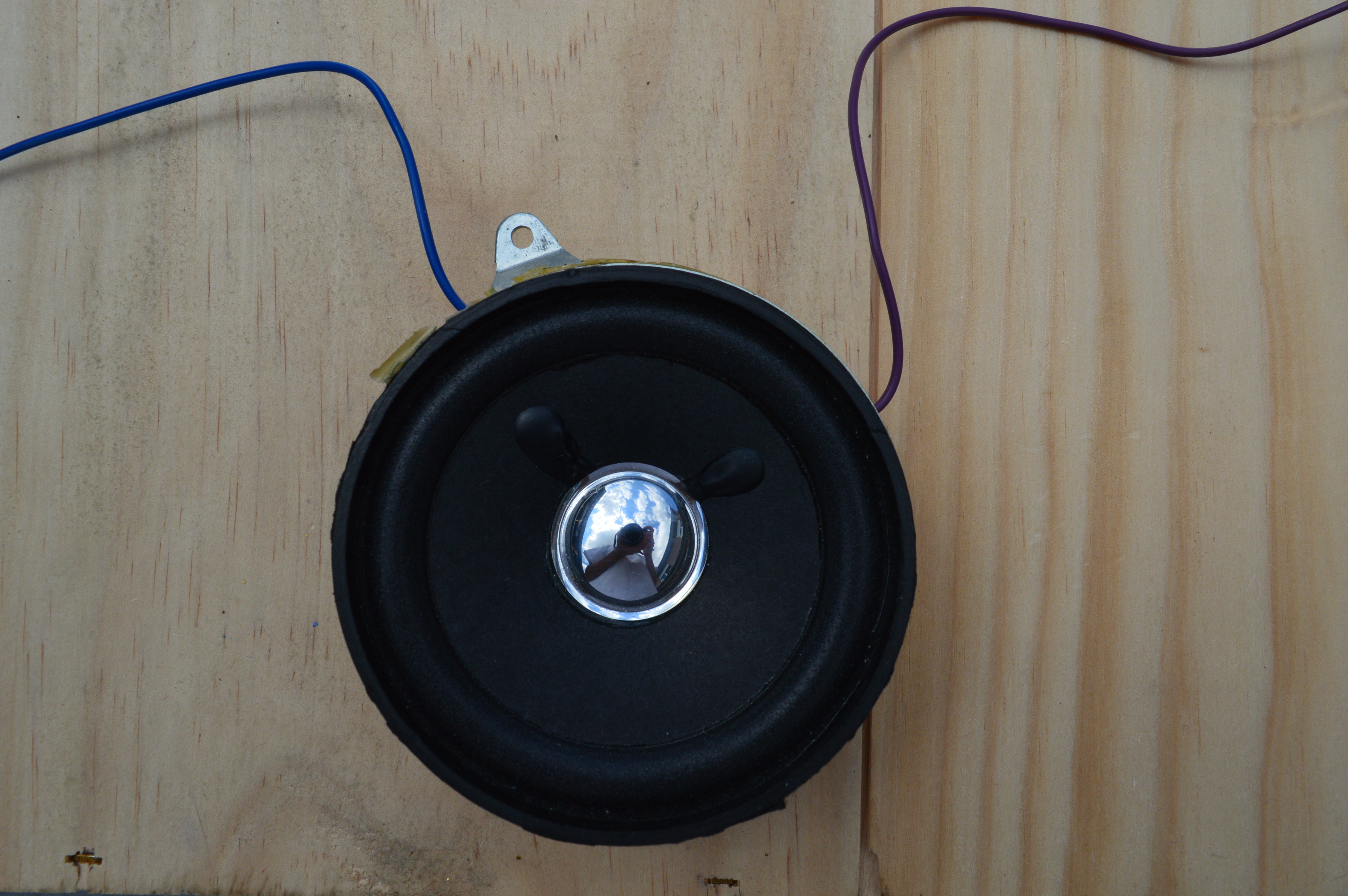
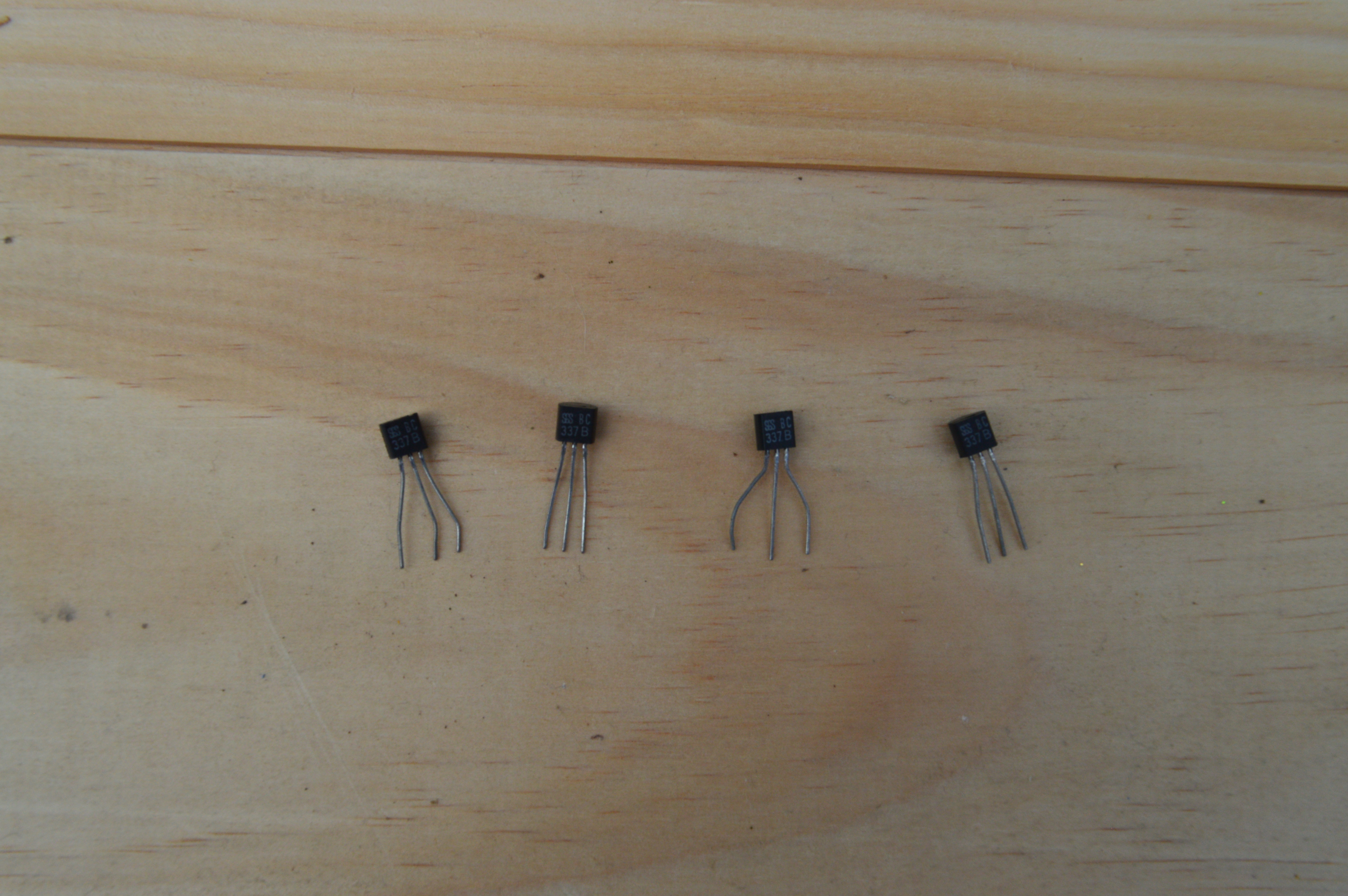
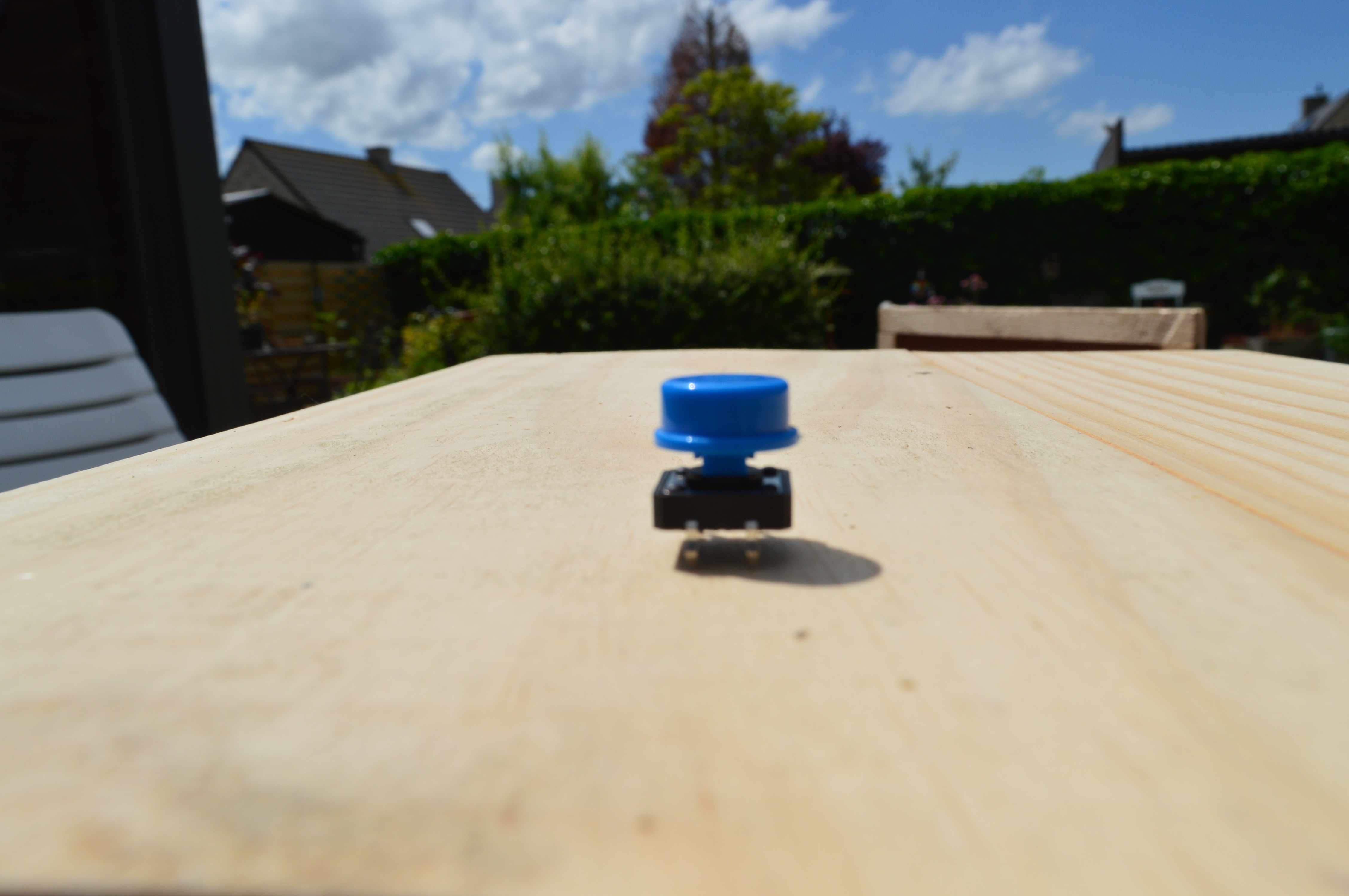
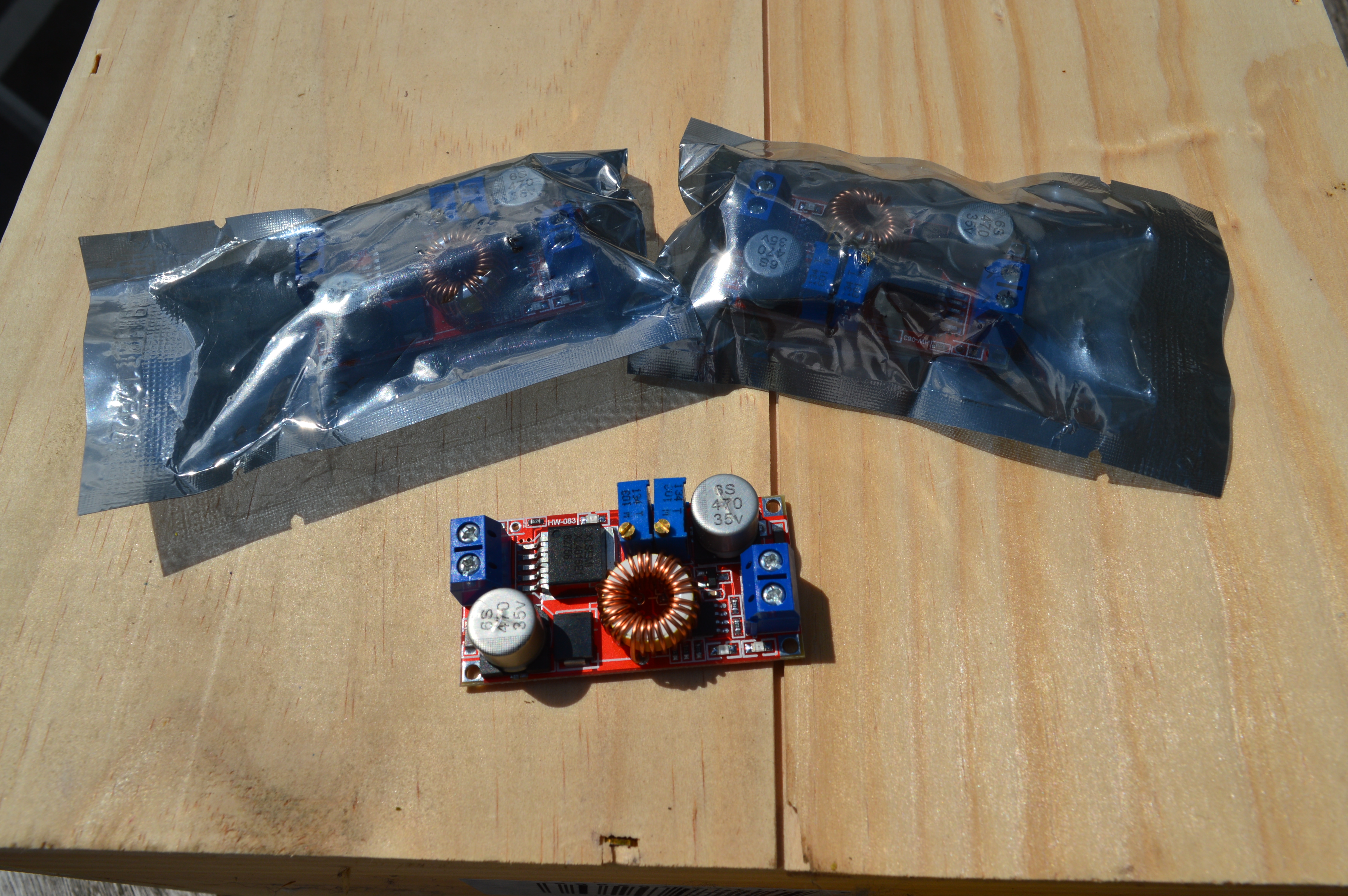
So, first things first, let’s make sure we have everything we need before we start building. I made a list of the most important components. Underneath you can find a pdf with more detailed info on the components.
- 1 x Raspberry Pi 3 model B
- 1 x (empty) microSD card and adapter (I have a 16GB card, but 8GB is enough)
- 1 x 5V Power supply for Raspberry Pi
- 1 x ethernet cable
- 2 x 9V batteries
- 2 x 9V battery clips
- 1 x GPIO 40 pin expansion board and rainbow cable
- 2 x BB830 Solderless Plug-in Breadbord
- 1 x Arduino Uno
- 1 x 0.56 inch 4*7 segment display
- 1x DS18B20 temperature sensor
- 1 x TSL2561 luminosity sensor
- 1 x 1602A LCD-screen
- 1 x level converter
- 1 x SN74HC595N shiftregister
- 1 x Rotary Encoder
- 1 x potentiometer
- 1 x Power RGB LED
- 1 x speaker
- 4 x 337B Transistors
- 1 x diode
- 1 x button
- 3 x xl4005 31 LED driver
- 7 x resistors (2 x 10k Ohm , 4 x 1k Ohm, 1 x 470 Ohm)
- Various jumper wire cables (male to male and male to female)
Optional:
- 1 x multiplex wood panel (I used one with the following measurements which was more than enough: 860mm x 860mm x 5mm)
- Various tools for woodworking
- Acrylic paint in a colour you like
Step 2: Schematics
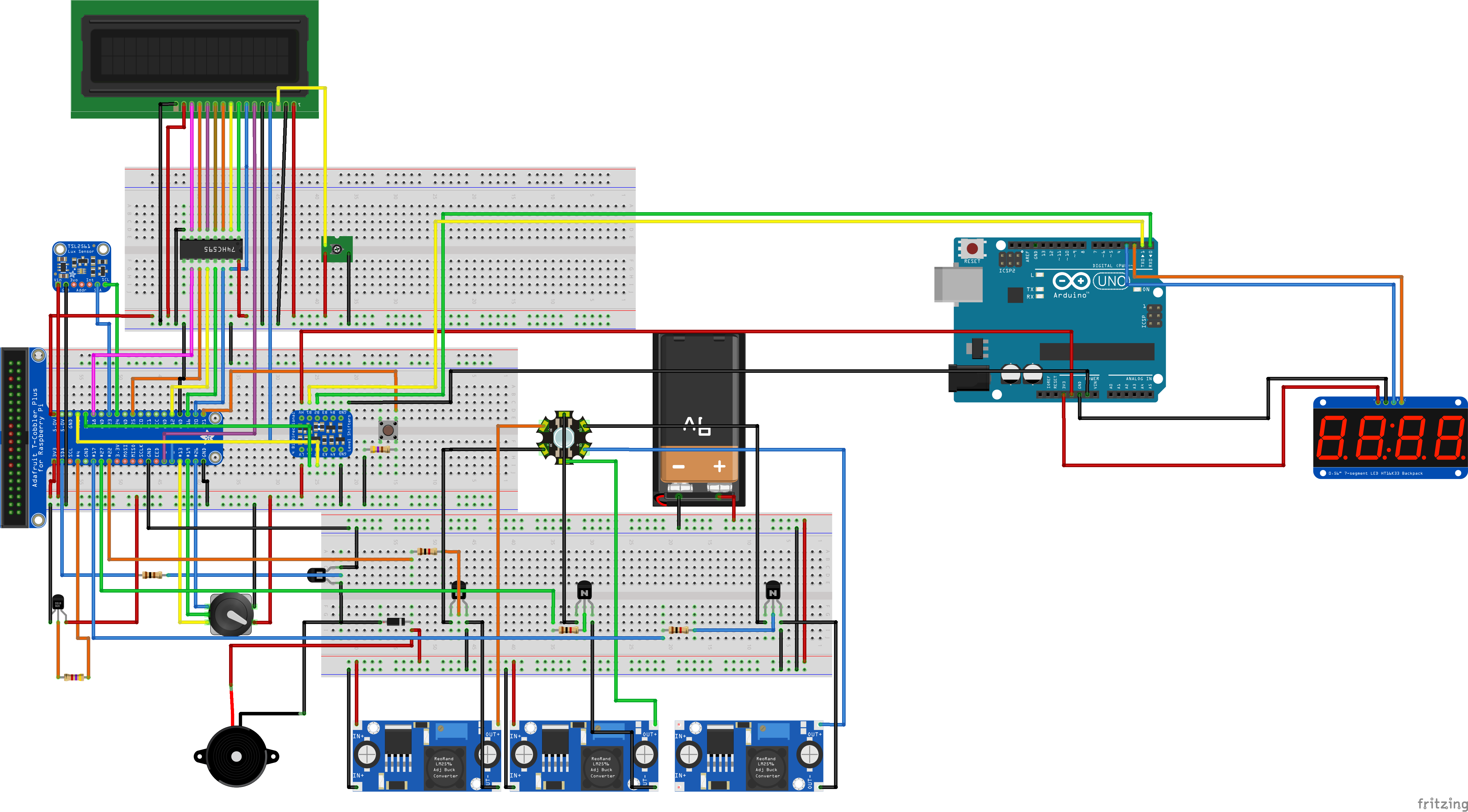
After collecting all the components, I could starting connecting everything. First I made a Fritzing schematic to make sure I wouldn’t fry any components by connecting them wrong. After some feedback from my teachers, I made some corrections which resulted in the following schematic diagram and wiring diagram:
Most of the GPIO pins are interchangeable, so you can switch a few of them if you want. Don’t forget to change the pin numbers in the code accordingly though.
Some elements must be connected to certain pins however. Make sure the luminoscity sensor is connected to GPIO 23 (SDA) and GPIO 24 (SCL) respectively. I’ll explain why this is important in step 5.
Step 3: Raspberry Pi Setup
Now it's time to set up our Pi:
1. Put your microSD card inside the adapter and plug it into your pc.
If your microSD card is not empty, then format it first via your preferred method.
2. Install the Raspbian OS software from the Raspberry pi website.
Download the ZIP file and extract it to a desired location.
3. Download the Win32 disc manager.
Click on the folder icon to select the image Select your microSD at "Device" Click on "Write"
When the image is written on your MicroSD card, you can open it in Windows Explorer.
Open the file "cmdline.txt" At the end of the file, add the following line of text: ip=169.254.10.1 Make sure everything is on the same line. Save the file.
Now eject the MicroSD card from your computer. Make sure the power of your Pi is turned off and insert the card in your Raspberry Pi.
Connect an ethernet cable to your Pi and your computer.
Apply power to your Pi with a 5,2V power adapter.
Step 4: Connecting Raspberry Pi
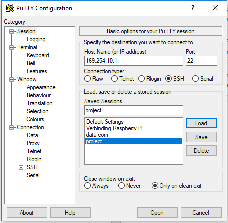
To connect
the Pi with our computer, we’ll use Putty.
1. Install Putty and open it.
2. Fill in the IP address and port as shown in the picture and click ‘open’.
3. Login with the following defaults:
a. Username: pi
b. Password: raspberry
4. To set up the WiFi:
a. Sudo nano /etc/wpa_supllicant/wpa_supllicant.conf
b. At the bottom of the file, add these lines:
i. Network = {
ii. ssid=”Fill in name of your wireless network”
iii. psk=”Fill in password of your wireless network”
iv. }
c. Close the file and save it
5. Enter the following command to figure out the IP address of your Pi: ifconfig wlan0
6. You can now use this IP address in Putty to make a wireless connection (see above).
Step 5: Change Settings With Raspi-config
Now we need to make sure the Pi can communicate with all our components.
We’ll change some settings in raspi-config
- Open raspi-config with the command:
sudo raspi-config
2. Select 4 Localisation Options.
3. Select I2 Change Timezone.
4. Change the timezone to your local timezone and finish to go back to raspi-config.
5. Select 5 Interfacing Options.
6. Select P5 I2C.
7. Enable I2C communication.
8. Select 5 Interfacing Options
9. Select P6 Serial
10. Disable login shell.
11. Enable serial communication
Step 6: Change Settings in /boot/config.txt
Now we must reconfigure some things in the file /boot/config.txt
1. Access the file:
sudo nano /boot/config.txt
2. At the bottom you should see:
enable_uart=1
This is because we enabled the serial port earlier.
3. Add the following two lines:
dtoverlay=pi3-miniuart-bt
dtoverlay=i2c-gpio,bus=3
The Raspberry Pi 3 has 2 serial ports: a hardware serial port and a software serial port. With the first command we assign the software serial port to the Bluetooth function and assign the hardware serial port to the Rx and Tx pins which we’ll use to communicate with the Arduino.
The second line activates a software I²C bus on the Pi. This is because the hardware I²C bus sometimes gives errors when the sensor connected to this I²C bus uses clock stretching. The software I²C bus will automatically be active on GPIO 23 (SDA) and GPIO 4 (SCL) which is why it was so important to correctly connect the luminosity sensor which uses I²C to send data.
Step 7: Add the User to the Right Groups
Finally add the user to some groups:
1. Check to which groups your current user belongs:
groups your_username
2. For all functions to work, the user needs to belong to the following groups:
adm dialout sudo input netdev gpio i2c spi ·
If necessary, add the user to the appropriate groups:
sudo adduser your_username groupname
Step 8: Database
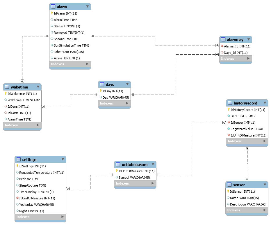
To be able to store the different alarm times set by the user and the different values of the sensors, I had to make a database. You can see the database schematic above.
To add the database to the Raspberry Pi, do the following steps:
1. Make a connection through Putty
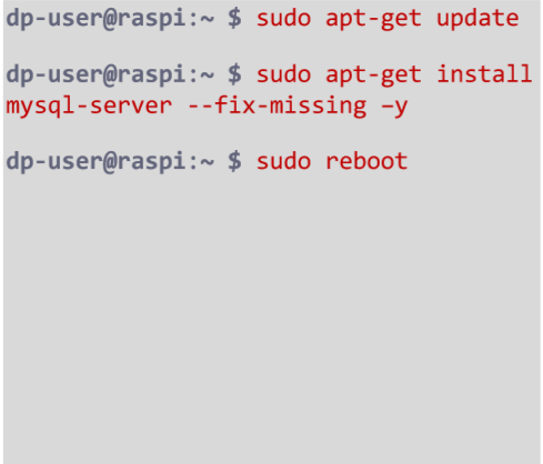
2. Update MySQL
sudo apt-get update
sudo apt-get install mysql-server --fix-missing -y
sudo reboot
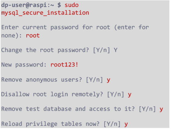
3. Secure MariaDB
sudo mysql_secore_installation
4. Login to MariaDB
sudo mysql -u root
5. The database currently has no users. We use this code to create a user, you just need to fill in the user and the password:
GRANT ALL PRIVILEGES ON *.* TO ‘fill_in_your_chosen_username’@’%’
IDENTIFIED BY ‘fill_in_your_chosen_password’ WITH GRANT OPTION;
<p>FLUSH PRIVILEGES;<br>EXIT;</p>
6. Download the database from Github.
7. Install workbench.
8. Make a connection in workbench with your pi and execute the file.
Step 9: Python Code
Step 10: Autorun the Python Code
1.Make a Putty connection with your Pi.
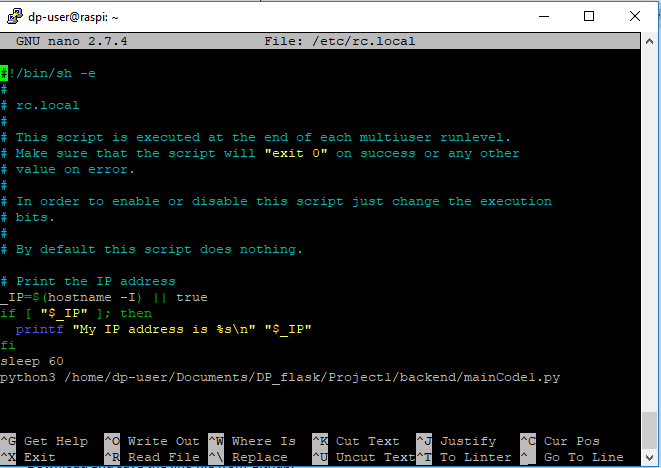
2. Open the file /etc/rc.local:
sudo nano /etc/rc.local
3. Before exit, add the following lines:
sleep 60
python3 /path_from_root_to_your_pythonfile/name_of_your_pythonfile.py
Step 11: Arduino Code
1. Download and save the .ino file from Github.
2. Connect your Arduino with your laptop through USB.
3. Disconnect the Rx and Tx cables that connect the Arduino with the Raspberry Pi.
4. Open the file and upload it to the Arduino.
5. Disconnect the Arduino from your laptop and reconnect the Rx and Tx cables correctly.
6. Give Power to the Arduino. The 4*7 segment display should now show 12:34
Step 12: Webserver
1. Install apache:
sudo apt install apache2 -y
2. Become owner off the /var/www/html directory:
sudo chown pi /var/www/html
3. Go to the directory:
cd /var/www/html
4. Check if you’re the owner instead of root:
ls -al
5. Download and open Filezilla
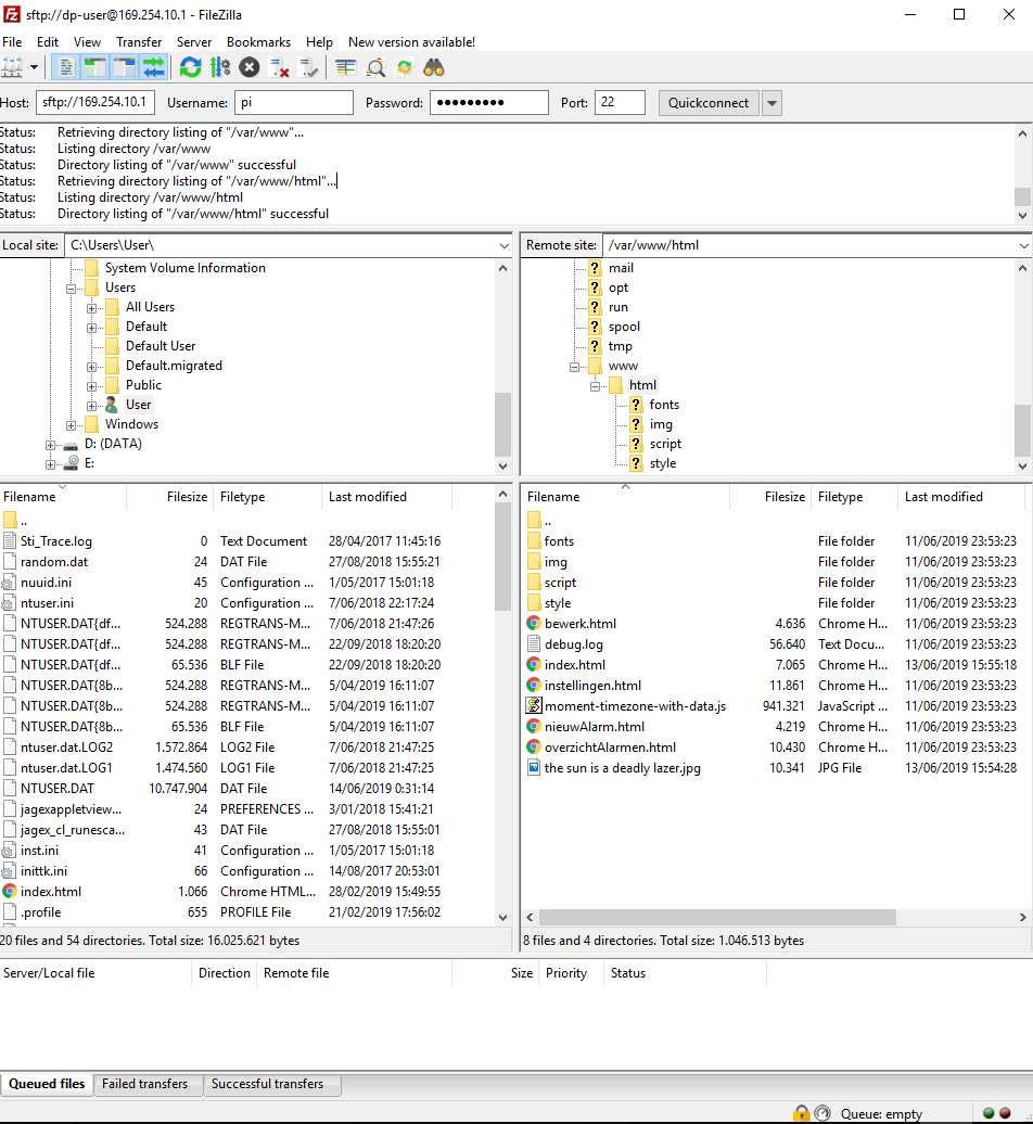
6. Make a connection with your pi as shown in the picture. (either use 169.254.10.1 and an ethernet cable or connect through wi-fi)
a. Go to the directory /var/www/html
b. Delete the default index.html page
c. Move all the frontend files into this directory
Step 13: Building the Outside

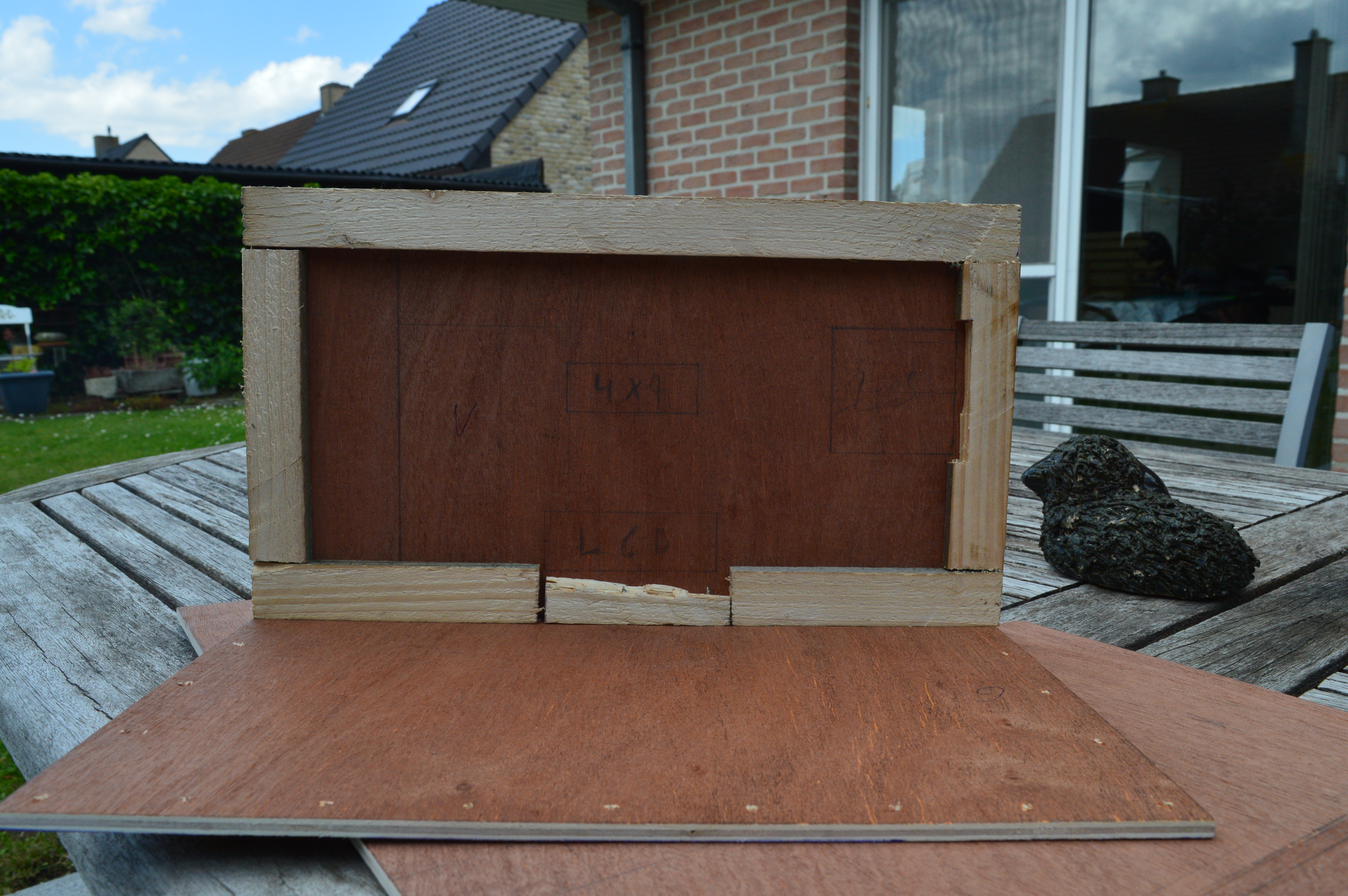
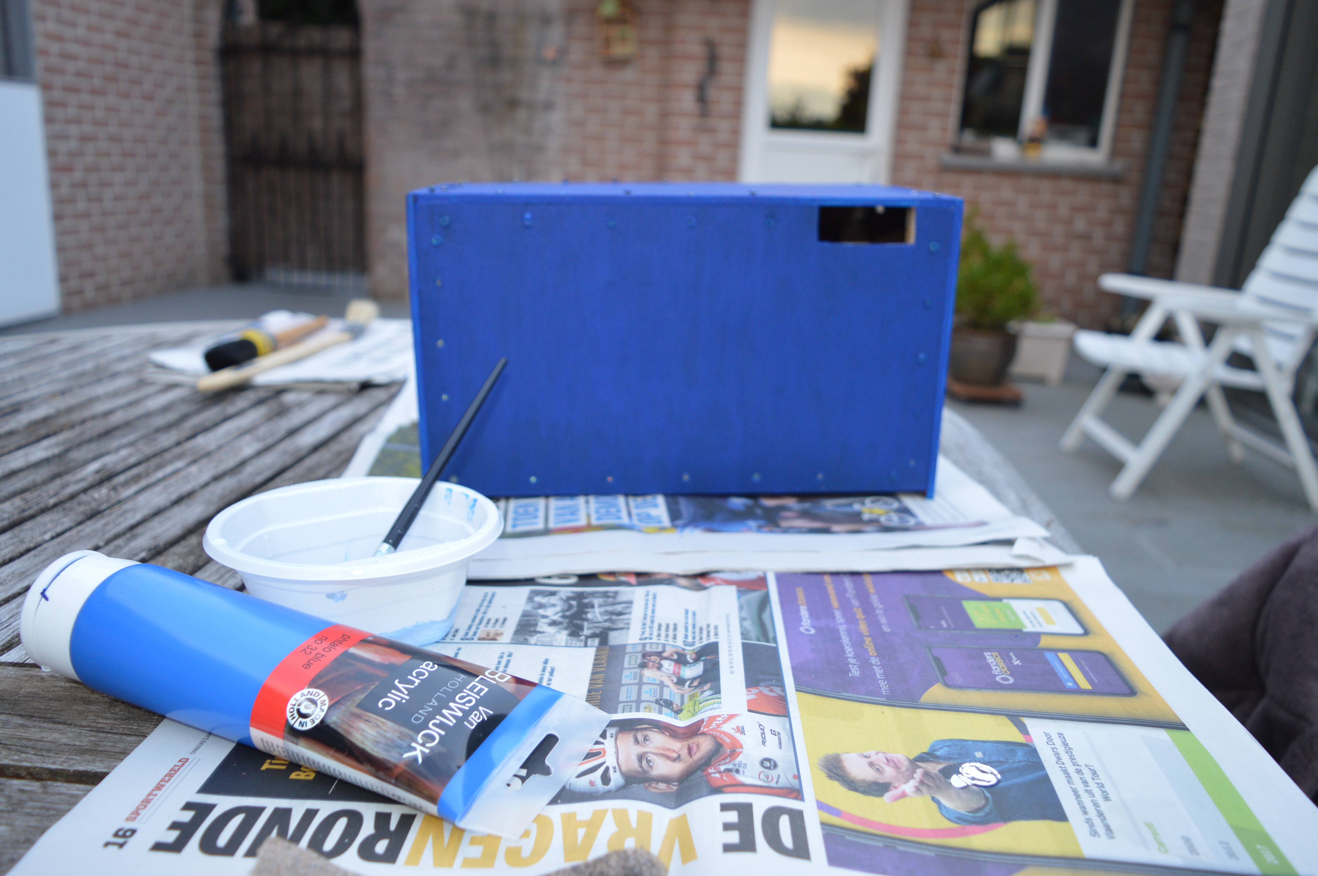
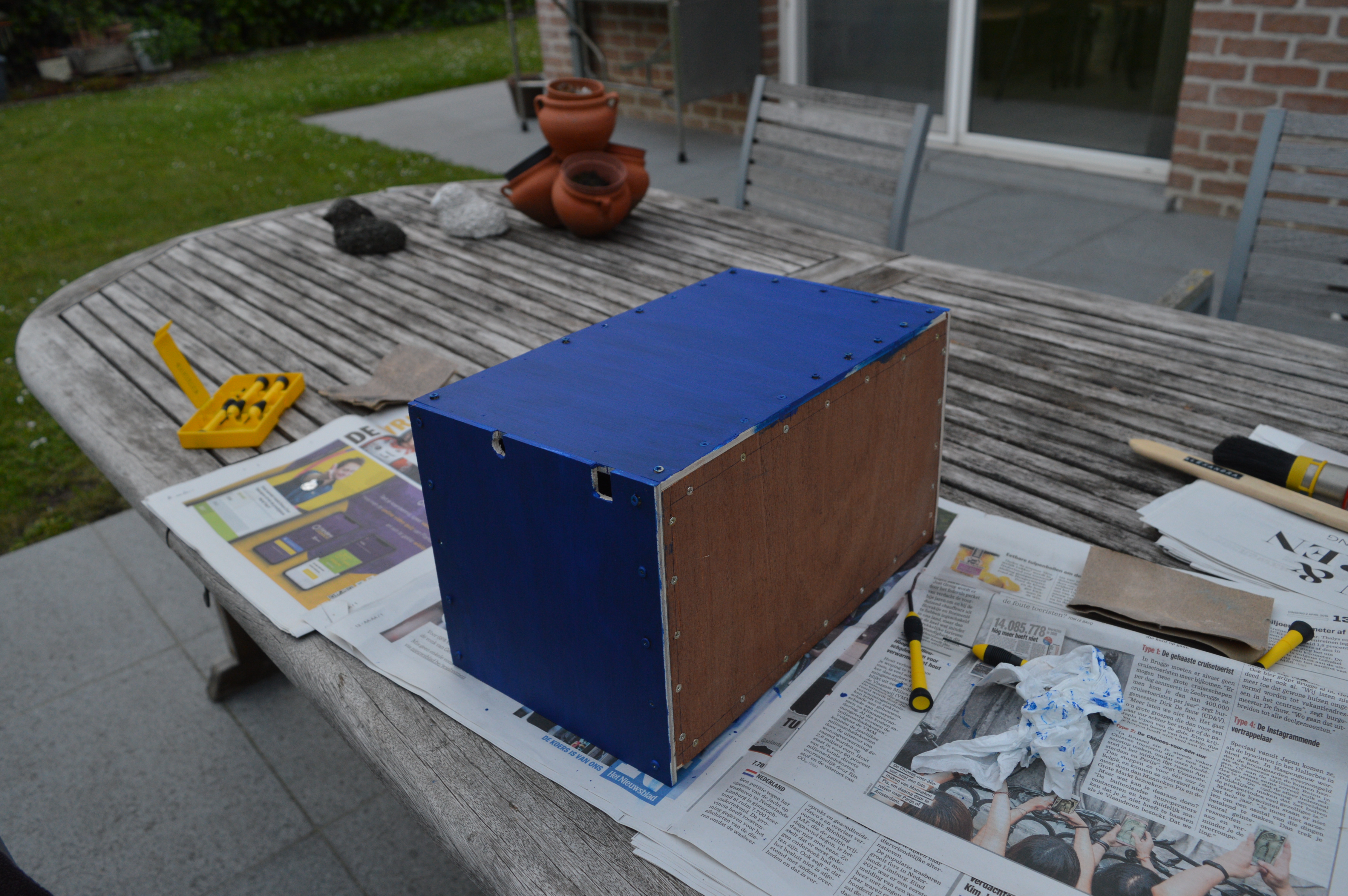
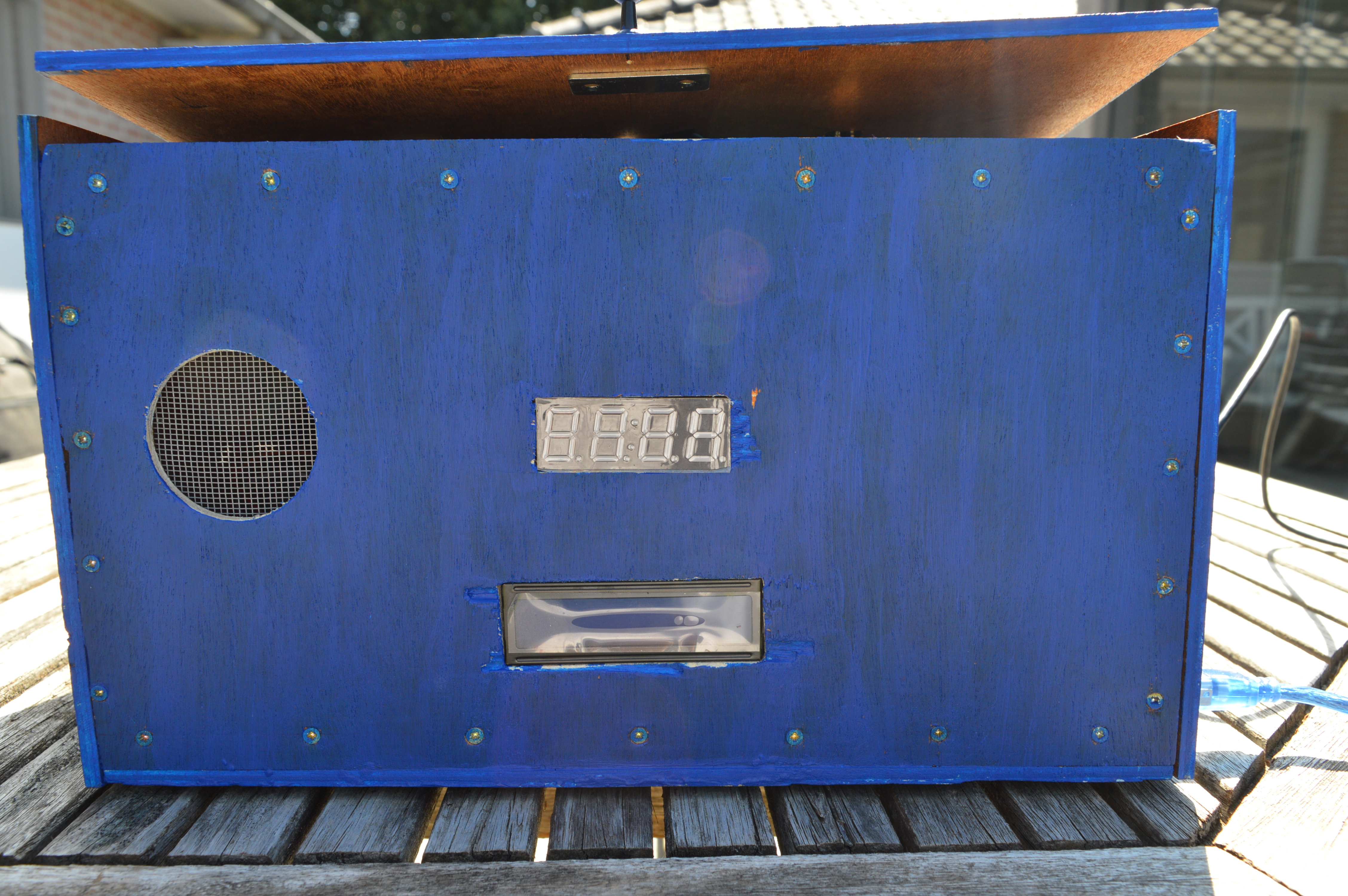
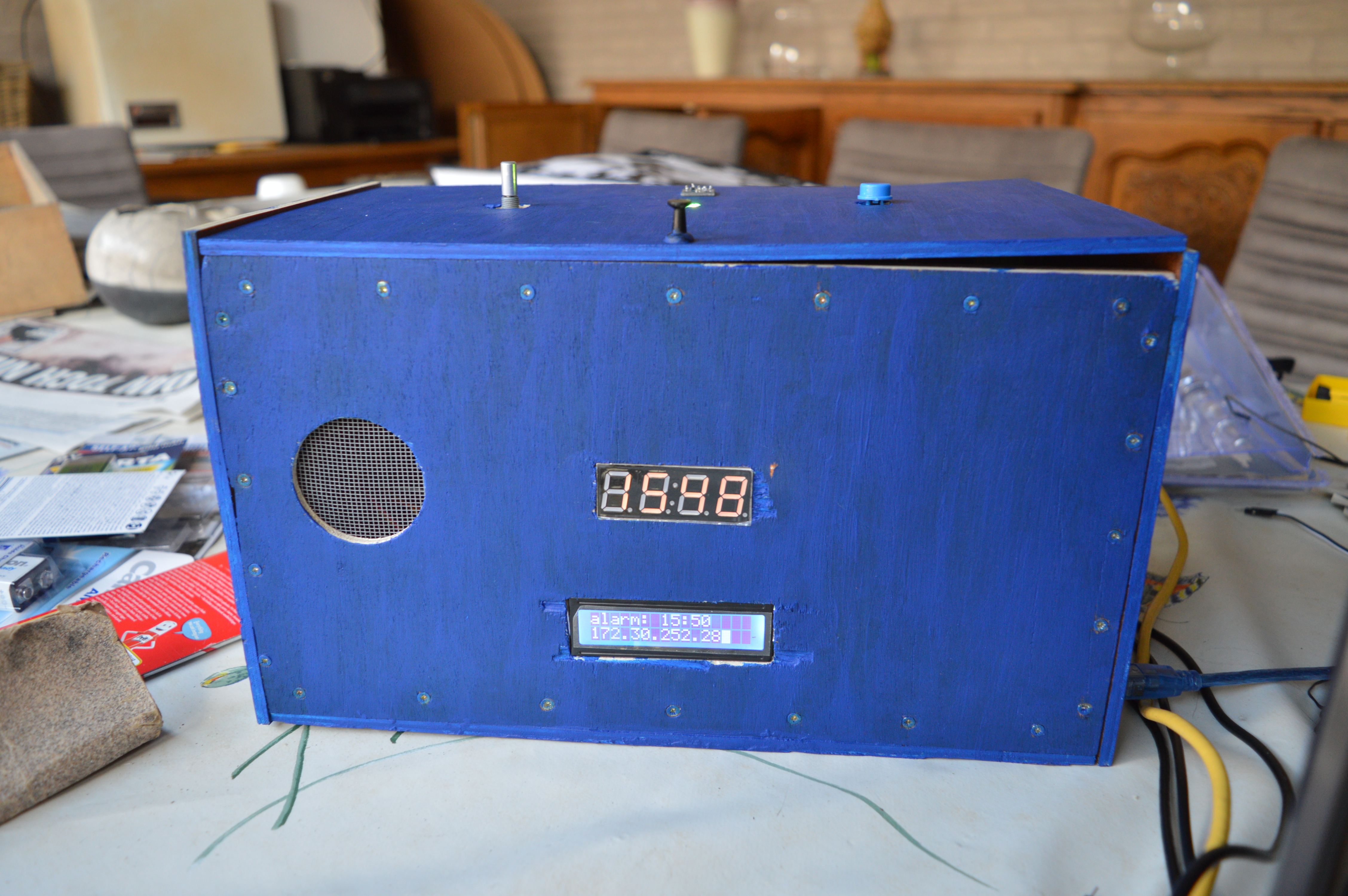
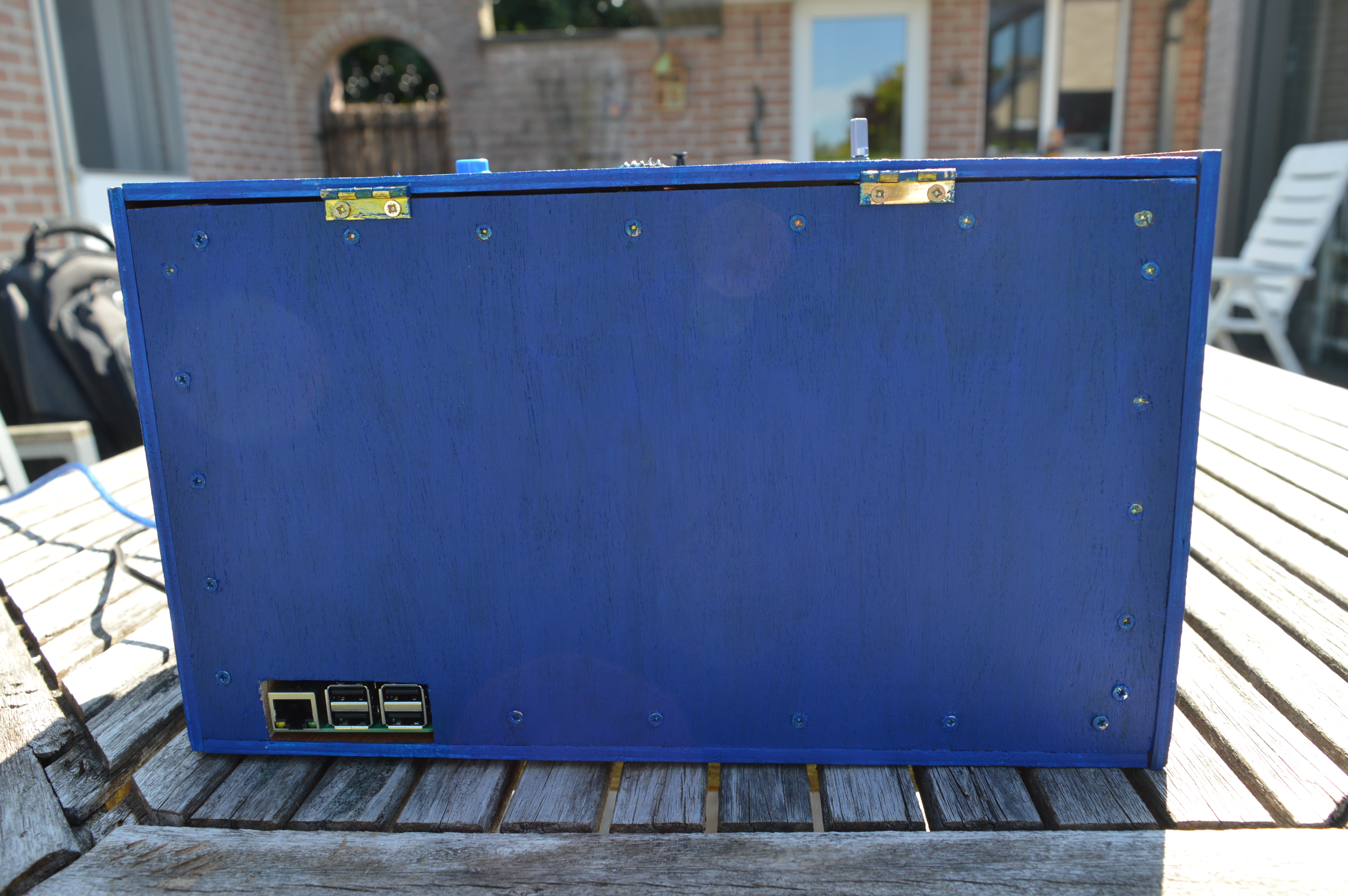
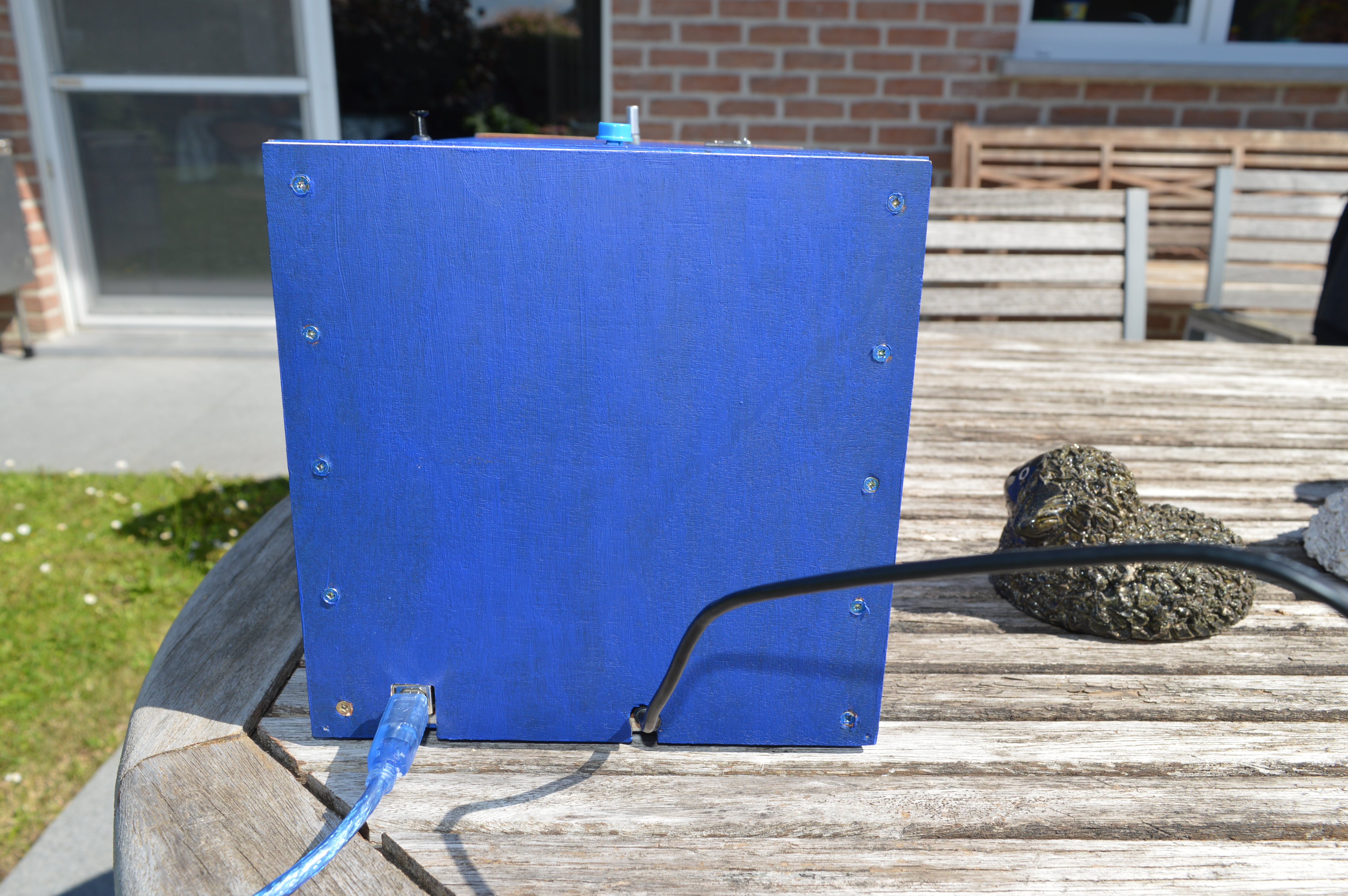
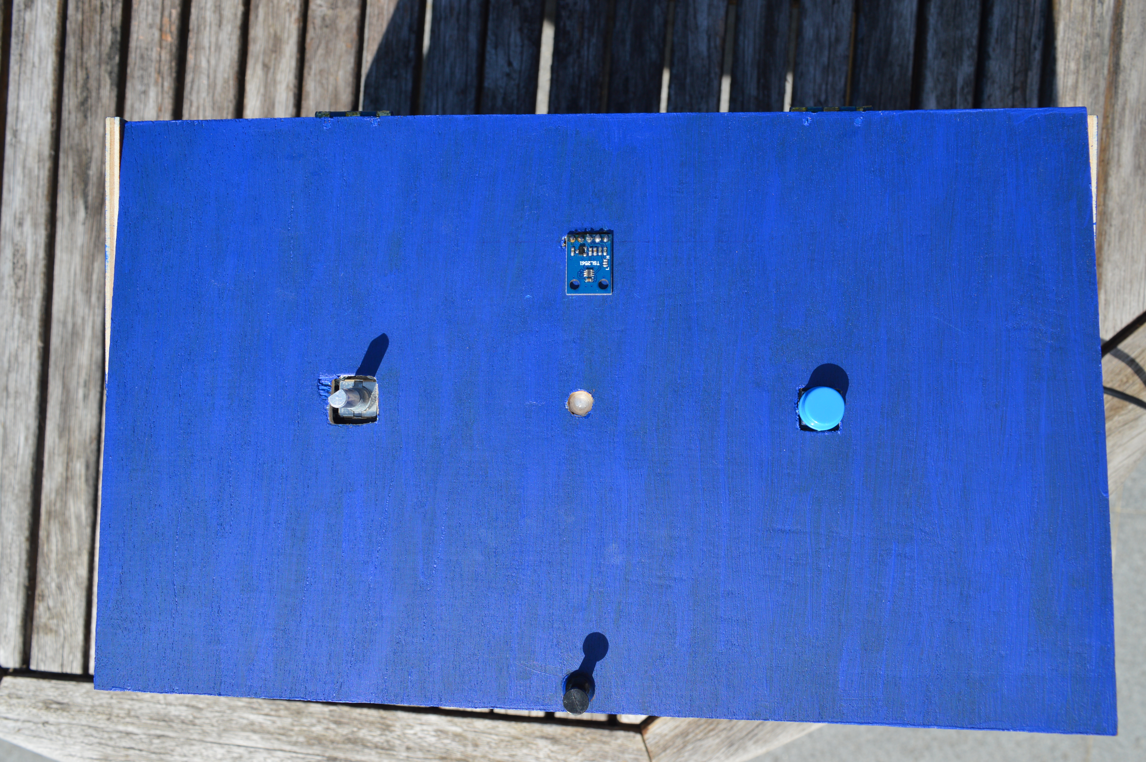
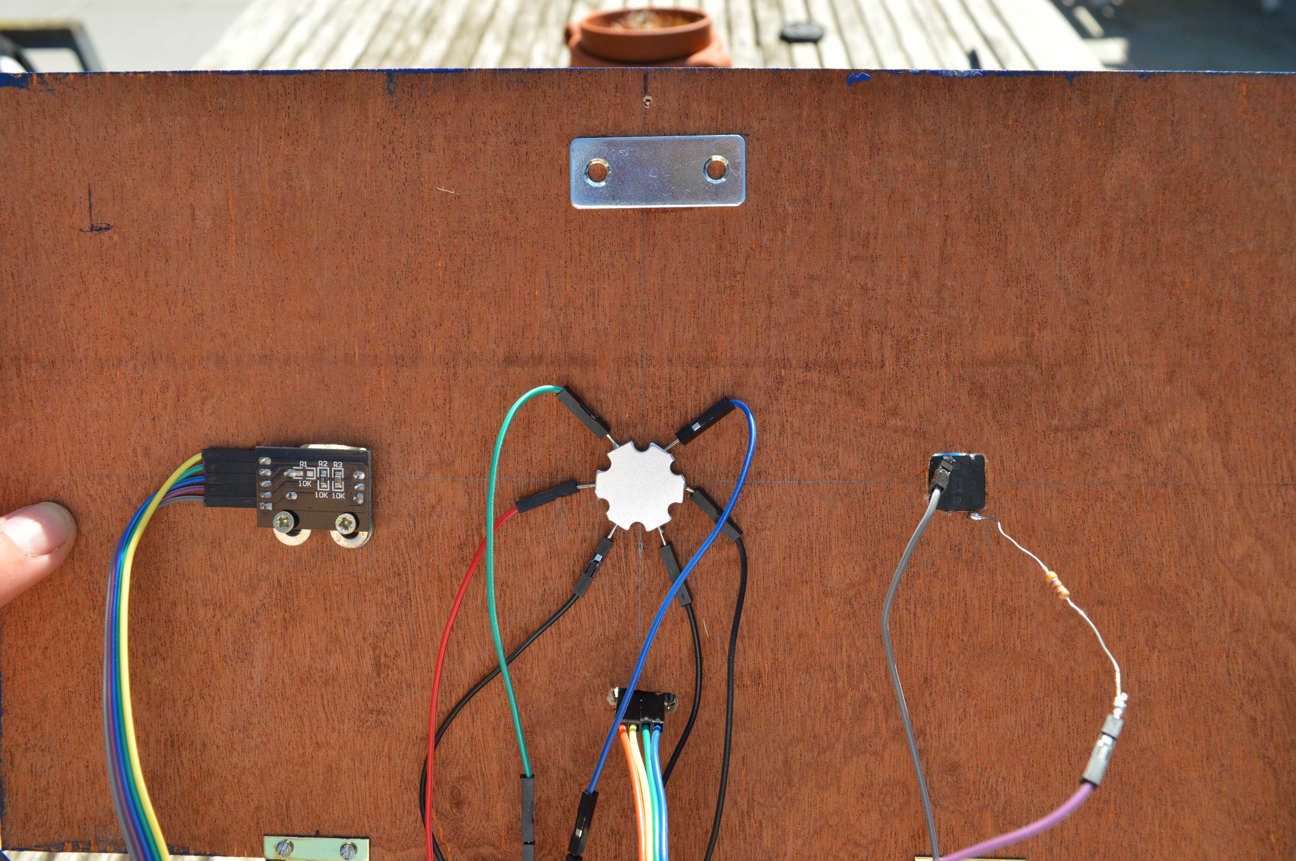
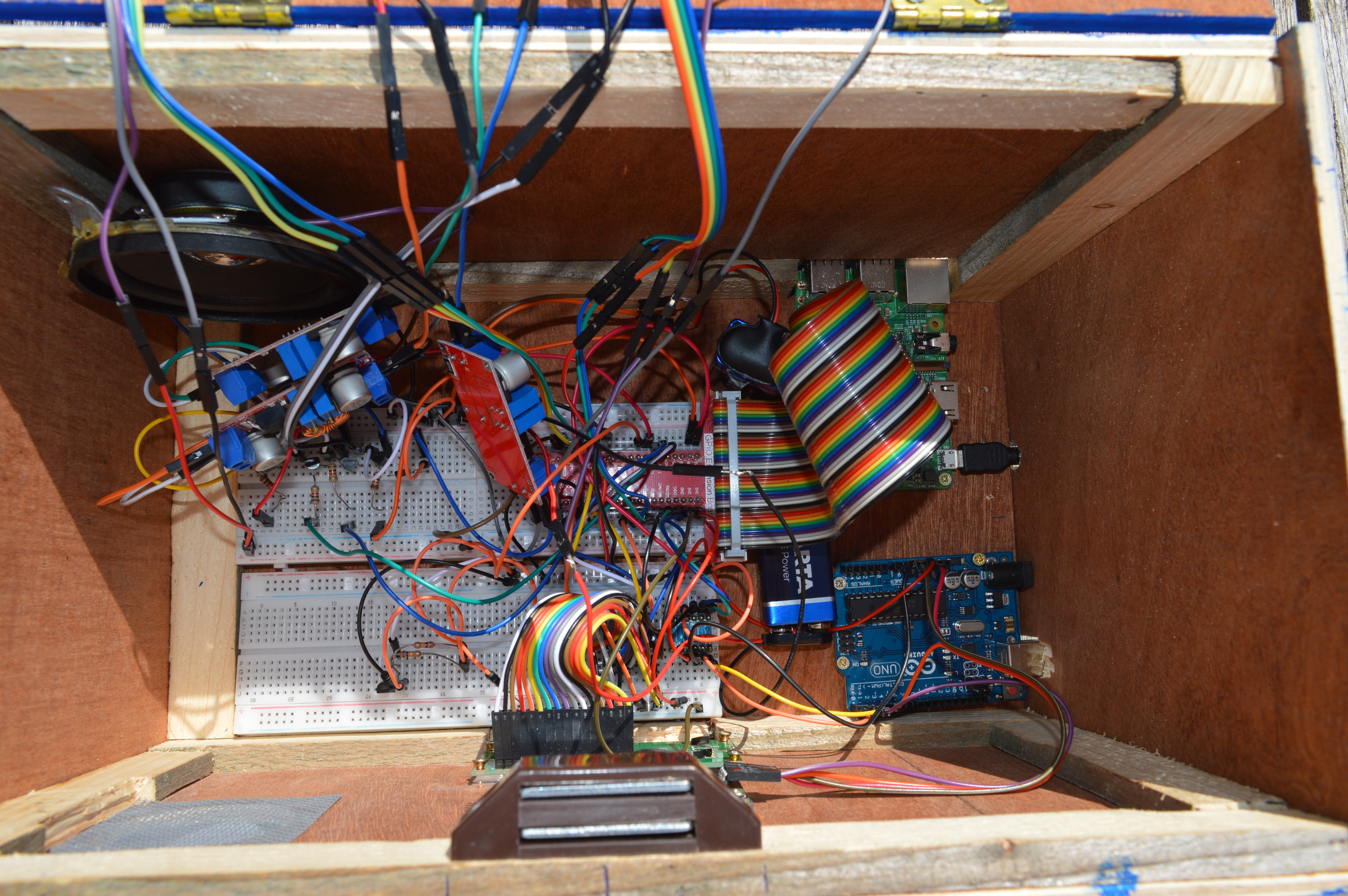
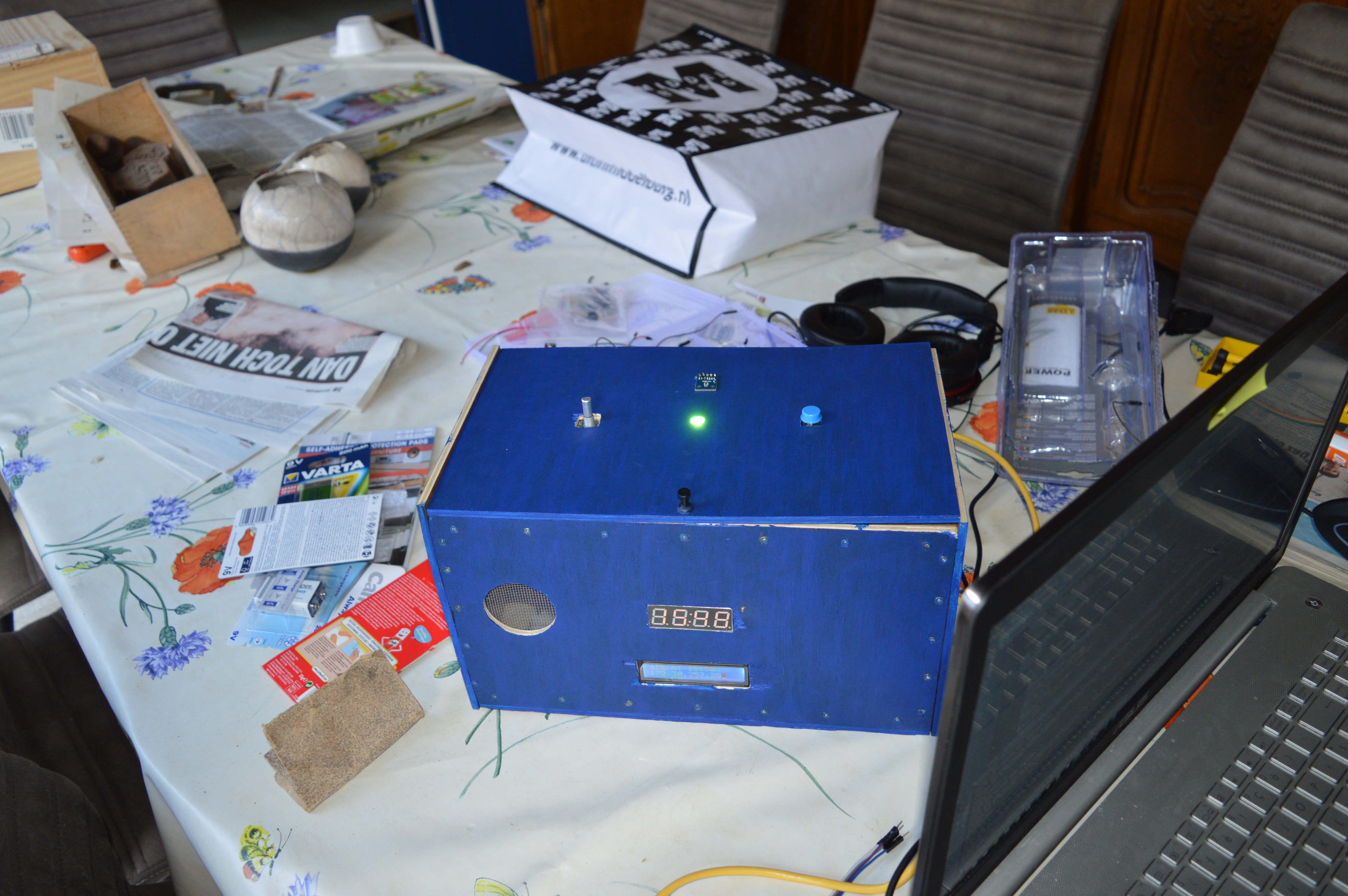
You can make the outside of the alarm clock however you like! I made a box for my alarm clock with a multiplex wood panel with a width of 5 mm. I you want to make something similar, these are the steps for said box:
1. Draw the following shapes on the multiplex panel:
Sides: 2 x square (180 mm x 180 mm)
Top and bottom: 2 x rectangle (180 mm x 300 mm)
Front and back: 2 x rectangle (170 mm x 300 mm)
2. Saw and sand each shape square and rectangle
3. Get some spare wood and make small planks of 20 mm high and 20 mm wide.
4. Screw the small planks to the insides (bottom, front and back) of the multiplex as seen in the photos.
5. Decide where you want to make the appropriate holes for the LCD-screen, 4*7 segment display, loudspeaker, luminoscity sensor, RGB LED, rotary encoder and button.
6. Measure every component that you want to show on the outside and draw appropriately sized shapes on the multiplex.
7. Cut out the necessary pieces.
8. Attach some hinges on the outside of the box, connecting the top and backside.
9. Attach a magnet on the inside of the front and a small metal plate on the inside of the topside.
10. Screw or glue everything where you want it.
11. Assemble the box by screwing all the outsides together (except the top).
You can skip 3 and 4 if you use smaller screws (I used 12 mm screws). Using smaller screws does slightly reduce the stability of the box however.